Mineral Insulated Band Heaters - Watlow
Mineral Insulated Band Heaters - Watlow
Mineral Insulated Band Heaters - Watlow

You also want an ePaper? Increase the reach of your titles
YUMPU automatically turns print PDFs into web optimized ePapers that Google loves.
<strong>Mineral</strong> <strong>Insulated</strong> <strong>Band</strong> <strong>Heaters</strong><br />
High Performance<br />
Heater—More Efficient<br />
Heat Transfer<br />
The mineral insulated (MI) band heater from <strong>Watlow</strong> ® is<br />
a high-performance heater that incorporates <strong>Watlow</strong>’s<br />
exclusive mineral insulation. This material offers much higher<br />
thermal conductivity than mica and hard ceramic insulators<br />
that are used in conventional heaters.<br />
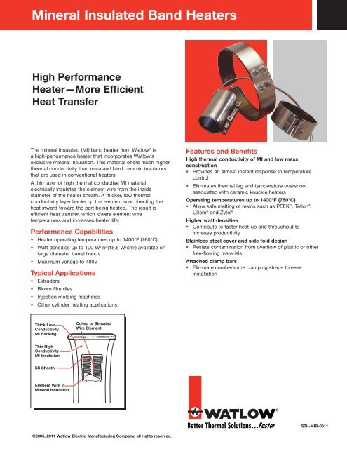
A thin layer of high thermal conductive MI material<br />
electrically insulates the element wire from the inside<br />
diameter of the heater sheath. A thicker, low thermal<br />
conductivity layer backs up the element wire directing the<br />
heat inward toward the part being heated. The result is<br />
efficient heat transfer, which lowers element wire<br />
temperatures and increases heater life.<br />
Performance Capabilities<br />
• Heater operating temperatures up to 1400°F (760°C)<br />
• Watt densities up to 100 W/in 2 (15.5 W/cm 2 ) available on<br />
large diameter barrel bands<br />
• Maximum voltage to 480V<br />
Typical Applications<br />
• Extruders<br />
• Blown film dies<br />
• Injection molding machines<br />
• Other cylinder heating applications<br />
Features and Benefits<br />
High thermal conductivity of MI and low mass<br />
construction<br />
• Provides an almost instant response to temperature<br />
control<br />
• Eliminates thermal lag and temperature overshoot<br />
associated with ceramic knuckle heaters<br />
Operating temperatures up to 1400°F (760°C)<br />
• Allow safe melting of resins such as PEEK , Teflon ® ,<br />
Ultem ® and Zytel ®<br />
Higher watt densities<br />
• Contribute to faster heat-up and throughput to<br />
increase productivity<br />
Stainless steel cover and side fold design<br />
• Resists contamination from overflow of plastic or other<br />
free-flowing materials<br />
Attached clamp bars<br />
• Eliminate cumbersome clamping straps to ease<br />
installation<br />
Thick Low<br />
Conductivity<br />
MI Backing<br />
Coiled or Sinuated<br />
Wire Element<br />
Thin High<br />
Conductivity<br />
MI Insulation<br />
SS Sheath<br />
Element Wire in<br />
<strong>Mineral</strong> Insulation<br />
®<br />
STL-MIB-0611<br />
©2005, 2011 <strong>Watlow</strong> Electric Manufacturing Company, all rights reserved.
Applications and Technical Data<br />
General Limitations<br />
• Maximum width of 1 in. (25 mm) diameter heater is<br />
1 1 ⁄2 in. (38 mm)<br />
• Maximum heater width: 2x heater diameter<br />
• Minimum I.D. for Type B, C, E and H leads: 1 in. (25 mm)<br />
• Minimum I.D. for Type B—90° leads: 1 1 ⁄8 in. (28.6 mm)<br />
• Maximum lead amperes: 12.5A per pair<br />
• SLE maximum: 17.0A<br />
• Maximum amperes (post terminals): 30A per pair<br />
• Minimum diameter and width for SLE: 4 in. x 1 1 ⁄2 in.<br />
(102 mm x 38 mm) width<br />
Termination Variations<br />
Type B<br />
Stock<br />
• 90° leads not available over 250VAC<br />
• Minimum I.D. for post terminals: 1 1 ⁄4 in. (32 mm)<br />
• Actual width for 7 in. (178 mm) wide heater:<br />
6 7 ⁄8 in. (174.6 mm)<br />
Gaps<br />
• ≤ 3 in. = 1 ⁄8 in. nominal<br />
• 3 in. ≤ 6 in. = 1 ⁄4 in. nominal ± 1 ⁄8 in.<br />
• 6 in. ≤14 in. = 3 ⁄8 in. nominal ± 1 ⁄8 in.<br />
• >14 in. = 1 ⁄2 in. nominal ± 1 ⁄4 in.<br />
Type B - 180° Rotation<br />
Stock<br />
0.36 in.<br />
(9 mm)<br />
12 in.<br />
(305 mm)<br />
0.81 in.<br />
(21 mm)<br />
0.16 in.<br />
(4.1 mm)<br />
0.16 in.<br />
(4.1 mm)<br />
I.D.<br />
I.D.<br />
1.25 in.<br />
(32 mm)<br />
Width ±0.0625 in.<br />
(1.6 mm)<br />
1.25 in.<br />
(32 mm)<br />
Type B - 90° Rotation<br />
Non-Stock<br />
Width ±0.0625 in.<br />
(1.6 mm)<br />
0.625 in.<br />
(15.9 mm)<br />
Nom.<br />
Type C<br />
Stock<br />
0.36 in.<br />
(9 mm)<br />
0.191 in.<br />
(4.9 mm)<br />
0.656 in.<br />
(16.7 mm) Dia.<br />
0.557 in.<br />
(14.1 mm)<br />
0.75 in.<br />
(19 mm) Nom.<br />
I.D.<br />
1.25 in.<br />
(32 mm)<br />
Width ±0.0625 in.<br />
(1.6 mm)<br />
Leads Type B, Type B - 90° rotation, Type B - 180° rotation or<br />
Type C: Two fiberglass-insulated lead wires exit in a single<br />
metal braid providing good abrasion protection, lead flexibility<br />
and wiring convenience. Leads are 2 in. (51 mm) longer than<br />
the braid and are shipped with 12 in. (305 mm) leads, unless<br />
a longer length is specified. To order, specify type and length.<br />
1.25 in.<br />
(32 mm)<br />
Width ±0.0625 in.<br />
(1.6 mm)<br />
Post Terminals<br />
Stock<br />
0.75 in.<br />
(19 mm)<br />
0.16 in.<br />
(4.1 mm)<br />
0.625 in. (15.9 mm)<br />
Nom.<br />
Post terminals provide optimum connections. The screw<br />
thread is 10-24. To order, specify post terminals (metric<br />
threads available).<br />
1.25 in.<br />
(32 mm)
Termination Variations (Continued)<br />
Type E<br />
Stock<br />
Type H<br />
Stock<br />
0.44 in.<br />
(11.2 mm) Dia.<br />
0.656 in.<br />
(16.7 mm) Dia.<br />
0.191 in.<br />
(4.9 mm)<br />
0.656 in.<br />
(16.7 mm) Dia.<br />
0.635 in.<br />
(16.1 mm)<br />
0.75 in.<br />
(19 mm) Nom.<br />
0.191 in.<br />
(4.9 mm)<br />
I.D.<br />
0.635 in.<br />
(16.1 mm)<br />
0.75 in.<br />
(19 mm) Nom.<br />
I.D.<br />
1.25 in.<br />
(32 mm)<br />
Width ±0.0625 in.<br />
(1.6 mm)<br />
Type E: A loose metal braid encloses two fiberglass leads to<br />
provide good abrasion protection, lead flexibility and wiring<br />
convenience. Leads are 2 in. (51 mm) longer than the braid<br />
and are shipped with 12 in. (305 mm) leads, unless a longer<br />
length is specified. To order, specify Type E and length.<br />
Type F<br />
Stock<br />
1.25 in.<br />
(32 mm)<br />
Width ±0.0625 in.<br />
(1.6 mm)<br />
Type H: A flexible steel hose encloses the leads for maximum<br />
abrasion protection. Leads are 2 in. (51 mm) longer than the<br />
hose and are shipped with 12 in. (305 mm) leads, unless a<br />
longer length is specified. To order, specify Type H and<br />
length.<br />
Type K<br />
Stock<br />
0.191 in.<br />
(4.9 mm)<br />
I.D.<br />
0.656 in.<br />
(16.7 mm) Dia.<br />
0.635 in.<br />
(16.1 mm)<br />
0.75 in.<br />
(19 mm) Dia.<br />
0.191 in.<br />
(4.9 mm)<br />
I.D.<br />
0.656 in.<br />
(16.7 mm) Dia.<br />
0.557 in.<br />
(14.1 mm)<br />
0.75 in.<br />
(19 mm) Nom.<br />
1.25 in.<br />
(32 mm)<br />
Width ±0.0625 in.<br />
(1.6 mm)<br />
Type F: A loose fiberglass sleeving encloses two fiberglass<br />
leads for additional insulation protection where high<br />
temperature or minor abrasion is present. Leads are<br />
2 in. (51 mm) longer than the sleeving. To order, specify<br />
Type F and length.<br />
1.25 in.<br />
(32 mm)<br />
Width ±0.0625 in.<br />
(1.6 mm)<br />
Type K: Flexible lead wires exit vertically from the heater.<br />
These leads can be bent adjacent to the heater for a quick<br />
and easy connection. To order, specify Type K and length.
Variations<br />
Thermocouple<br />
Heavy Duty Strain Relief<br />
0.25 in.<br />
(6 mm)<br />
Type SLE<br />
Spot Welded to<br />
Heater Sheath<br />
ASTM Type J or K thermocouples are available on lead<br />
Type B with loose braid and fiberglass sleeving. They are also<br />
available on E, F and H leads. The thermocouple junction,<br />
spot-welded to the heater sheath, provides a signal for<br />
measuring relative heater temperature. A separate<br />
thermocouple is available.<br />
Heavy duty strain relief is recommended for applications<br />
where there is great stress or continued flexing of the leads.<br />
The strain relief is available on Type B, Type B - 90° and<br />
Type B - 180° leads only. To order, specify heavy-duty strain<br />
relief. Note: not available with loose braid or fiberglass<br />
sleeving.<br />
Ground Wire<br />
<strong>Insulated</strong> ground wire is available. Contact a <strong>Watlow</strong><br />
representative for ordering information.<br />
Expandable <strong>Heaters</strong> With Post Terminals or Leads<br />
0.4375 in.<br />
(11.1 mm)<br />
Strain Relief<br />
Two fiberglass lead wires exit a single, tightly woven metal<br />
braid at a right angle on the expandable construction vs. two<br />
sets of leads. The minimum diameter capability is 4 in.<br />
(102 mm). Minimum width capability is 1 1 ⁄2 in. (38 mm). To<br />
order, specify Type SLE and length.<br />
1½ in. (38 mm) wide<br />
and greater<br />
Expandable heaters are two-piece units with a common top<br />
metal that allow the heater to expand to the full diameter of<br />
the barrel. On expandable bands, each half will comprise<br />
one-half of the total wattage. On both expandable and<br />
two-piece bands, each half is rated at full operating voltage,<br />
unless otherwise specified.<br />
Post terminals for MI band heaters 1 1 ⁄2 in. (38 mm) wide or<br />
greater are located next to the expansion joint. Leads may be<br />
located anywhere along the circumference except near the<br />
gap and at the expansion joint. Two sets of leads are<br />
required.<br />
On 1 in. (25 mm) wide MI band heaters, post terminals are<br />
located 90° from the expansion joint. Leads may be located<br />
anywhere along the circumference except near the gap and at<br />
the expansion joint. Two sets of leads are required. To order,<br />
specify expandable. Expandable heaters are designed to be<br />
opened for new installation only.
Variations (Continued)<br />
Lead Wire<br />
<strong>Heaters</strong> rated at less than 250VAC use UL ® approved lead<br />
insulation for operations up to 480°F (250°C) as standard.<br />
Lead insulation UL ® rated for operation to 840°F (450°C) is<br />
available for high-temperature applications where leads are<br />
shrouded or enclosed with the heater. These leads are<br />
available in any of the Type B variations with loose braid and<br />
Types E, F and H lead configurations. All heaters rated at<br />
more than 250VAC use this wire. When ordering, specify<br />
850°F (450˚C) wire.<br />
Metallic Terminal Box<br />
3½ in. for 3½-515⁄16 in. I.D.<br />
4 in. for 6-28 in. I.D.<br />
17⁄16 in.<br />
(36.5 mm)<br />
113⁄16 in.<br />
(46 mm)<br />
Ceramic Terminal Cover<br />
Ceramic covers with openings for leads are screwed on to<br />
post terminals, providing a convenient, economical insulator.<br />
To order, specify code number Z-4918 and quantity.<br />
For metric ceramic terminal covers, specify thread.<br />
Note: Ceramic terminal covers will not fit on some stock<br />
expandable MI bands. Contact a <strong>Watlow</strong> representative for<br />
more information<br />
Metallic terminal boxes are available from stock on 3 1 ⁄2 in.<br />
inside diameter x 1 1 ⁄2 in. wide (89 mm x 38 mm) or larger<br />
heaters. Terminal boxes attach directly to the heater and act as<br />
a safety feature by covering the terminals. The conduit may be<br />
attached to the box through 7 ⁄8 in. (22.2 mm) diameter holes in<br />
the ends of the box. Two-piece heaters require two boxes. To<br />
order, specify terminal box.<br />
MI <strong>Band</strong> Heater with Holes<br />
MI band heaters with holes are available on all widths<br />
except 1 in. (25 mm) wide. Contact your <strong>Watlow</strong><br />
representative for hole sizes and location constraints.<br />
To order, specify hole size and location. The inside<br />
diameter minimum is 3 in. (76 mm).
Clamping Variations<br />
Tig-Welded Barrel Nuts with Spring Loaded Clamping<br />
Tig-Welded Barrel Nuts<br />
¼ in. 2 Screw<br />
5⁄16 in. 18 Screw<br />
5.8 in. (147 mm)<br />
0.75 in.<br />
(19 mm)<br />
Tig Welded<br />
0.563 in.<br />
(14.3 mm)<br />
Welded barrel nuts with spring loaded clamping are used<br />
during start-up to maintain a tight heater fit on large barrels.<br />
This clamping variation is used for all MI band heaters<br />
greater than 14 in. (356 mm) in diameter and 1 1 ⁄2 in. (38 mm)<br />
or greater in width. Refer to the MI <strong>Band</strong> Clamping Matrix<br />
Application Guide. For smaller diameter heaters, this is an<br />
option and must be ordered separately. To order, specify<br />
spring loaded clamping.<br />
Low-Profile Tig-Welded Barrel Nuts<br />
Low-profile barrel nuts are available on all widths and<br />
provide a clearance of 0.470 in. (12 mm). However, this<br />
value can be higher depending on how far the clamp screw<br />
extends past the barrel nut. To order, specify low-profile<br />
tig-welded barrel nuts.<br />
Provide access for instrumentation by specifying an<br />
oversized gap between the heater ends. If the clamp bar<br />
screw interferes with the positioning of the instrumentation<br />
device, welded barrel nuts are recommended (tig-welded<br />
barrel nuts are standard on 1 in. (25 mm) wide MI band<br />
heaters). To order, specify tig-welded barrel nuts and gap<br />
dimension when ordering.<br />
Low-Profile Clamp Bars<br />
0.45 in.<br />
(11.4 mm)<br />
I.D.<br />
8-32 Screw<br />
Low-profile clamp bars are available on both<br />
1 in. (25 mm) and 1 1 ⁄2 in. (38 mm) wide heaters. For wider<br />
widths, contact your <strong>Watlow</strong> representative. <strong>Watlow</strong> does<br />
not recommend using low-profile clamping on diameters<br />
and widths greater than 3 in. (76 mm) The bars are 1 ⁄4 in.<br />
(6 mm) diameter with an 8-32 screw. To order, specify<br />
low-profile clamp bars.<br />
<strong>Watlow</strong> ® is a registered trademark of <strong>Watlow</strong> Electric Manufacturing Company.<br />
PEEK is a trademark of Victrex PLC.<br />
Teflon ® and Zytel ® are registered trademarks of E.I. duPont de Nemours &<br />
Company.<br />
Ultem ® is a registered trademark of General Electric Company.<br />
To be automatically connected to the nearest North American Technical Sales Office:<br />
1-800-WATLOW2 • www.watlow.com • inquiry@watlow.com<br />
International Technical Sales Offices: Australia, +61 3 9335 6449 • China, +86 21 3532 8532 • France, +33 1 41 32 79 70<br />
Germany, +49 (0) 72 53 / 94 00-0 • Italy, +39 024588841 • Japan, +81 3 3518 6630 • Korea, +82 2 2628 5770<br />
Malaysia, +60 3 8076 8745 • Mexico, +52 442 217 6235 • Singapore, +65 6773 9488 • Spain, +34 91 675 12 92<br />
Taiwan, +886 7 288 5168 • United Kingdom, +44 (0) 115 964 0777