
Create successful ePaper yourself
Turn your PDF publications into a flip-book with our unique Google optimized e-Paper software.
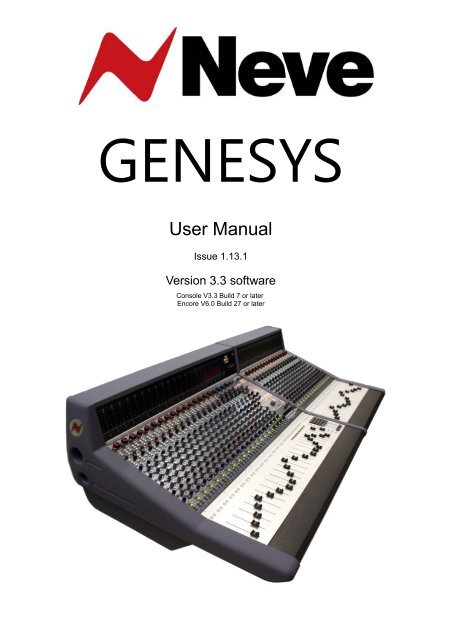
GENESYS<br />
<strong>User</strong> <strong>Manual</strong><br />
Issue 1.13.1<br />
Version 3.3 software<br />
Console V3.3 Build 7 or later<br />
Encore V6.0 Build 27 or later
IMPORTANT SAFTY INSTRUCTIONS<br />
▶ Read these instructions<br />
▶ Keep these instructions<br />
▶ Heed all warnings<br />
▶ Follow all instructions<br />
▶ Do not use this apparatus near water<br />
▶ Clean only with a dry cloth<br />
▶ Do not block any ventilation openings.<br />
▶ Install in accordance with the manufacturer's<br />
instructions.<br />
▶ Do not install near any heat sources such as radiators,<br />
heat registers, stoves or other apparatus (including<br />
amplifiers) that produce heat.<br />
▶ Do not defeat the safety purpose of the polarized or<br />
grounding-type plug.<br />
A polarized plug has two blades and a third grounding<br />
prong.<br />
The wide blade or the third prong are provided for your<br />
safety.<br />
If the provided plug does not fit into your outlet, consult an<br />
electrician for replacement of the obsolete outlet.<br />
As this apparatus is constructed to Class I, it shall be<br />
connected to a MAINS socket outlet with protective<br />
earthing connection.<br />
▶ Protect the power cord from being walked on or pinched<br />
particularly at plugs, convenience receptacles, and the<br />
point where they exit the apparatus.<br />
Where the MAINS plug or an appliance coupler is used as<br />
the disconnect device, the disconnect device shall remain<br />
readily operable.<br />
▶ Only use attachments / accessories specified by the<br />
manufacturer.<br />
▶ Use only with the cart, stand, tripod, bracket or table<br />
specified by the manufacturer, or sold with the apparatus.<br />
When a cart is used, use caution when moving the cart /<br />
apparatus combination to avoid injury from tip-over.<br />
▶ Unplug this apparatus during lightning storms or when<br />
unused for long periods of time.<br />
▶ Refer all servicing to qualified service personnel.<br />
- 2 -
Servicing is required when the apparatus has been<br />
damaged in any way, such as power-supply cord or plug is<br />
damaged, liquid has been spilled, or objects have fallen<br />
into the apparatus, the apparatus has been exposed to rain<br />
or moisture, does not operate normally or has been<br />
dropped.<br />
WARNING:<br />
TO REDUCE THE RISK OF FIRE OR ELECTRIC SHOCK, DO<br />
NOT EXPOSE THIS APPARATUS TO RAIN OR MOISTURE.<br />
WARNING:<br />
THIS APPARATUS HAS CLASS I CONSTRUCTION AND SHALL<br />
BE CONNECTED TO A MAINS SOCKET OUTLET WITH A<br />
PROTECTIVE EARYTHING CONNECTION.<br />
WARNING:<br />
WHERE THE MAINS PLUG OR AN APPLIANCE COUPLER IS<br />
USED AS THE DISCONNECT DEVICE, THE DISCONNECT<br />
DEVICE SHALL REMAIN READILY OPERABLE.<br />
- 3 -
Symbols used in this manual and on rear of console<br />
Please refer to the manual before operating<br />
Danger of electric shock<br />
Disconnect from the MAINS before opening cover<br />
Heat source<br />
No user serviceable parts inside<br />
Environmental considerations<br />
Temperature Operating 5°C to 22°C<br />
(41°F to 72°F)<br />
Non-operating -20°C to 50°C<br />
(-2°F to 122°F)<br />
Max Gradient 15°C/Hour<br />
(59°F/Hour)<br />
Relative Humidity Operating 20% to 80%<br />
Non-operating 5% to 90%<br />
Max wet bulb 28°C non-condensing<br />
(or 57°F non-condensing)<br />
Altitude Operating 0 to 2,000m<br />
Non-operating 0 to 12,000m<br />
Cooling<br />
Each sixteen-channel section has it's own PSU (Power<br />
Supply Unit) system located at the rear of the console.<br />
Care must be taken not to place any accessories that could<br />
block the ventilation above or below the heat sinks at the<br />
rear of the console.<br />
All PSU's will operate over an ambient temperature range<br />
of -10°C to +22°C (14°F to 72°F).<br />
The console must not be powered up or operated with the<br />
dust cover still in place.<br />
- 4 -
Health & Safety Notice<br />
FOR YOUR OWN SAFETY AND THE PROTECTION OF<br />
OTHERS, PLEASE OBSERVE THE FOLLOWING SAFETY<br />
HEALTH AND SAFETY INSTRUCTIONS<br />
▶ READ THESE INSTRUCTIONS AND KEEP THEM HANDY<br />
▶ HEED ALL SAFETY WARNINGS<br />
▶ THE CONSOLE MUST BE EARTHED WHEN OPERATED<br />
▶ DO NOT USE NEAR WATER<br />
▶ CLEAN ONLY WITH A DRY CLOTH<br />
▶ DO NOT INSTALL NEAR HEAT SOURCES<br />
▶ DO NOT BLOCK VENTILATION OPENINGS<br />
▶ THE AMBIENT ROOM TEMPERATURE SHOULD BE NO GREATER THAN 22°C / 72°F<br />
▶ PROTECT THE POWER CORDS<br />
▶ USE ONLY ACCESSORIES SPECIFIED BY THE MANUFACTURER<br />
▶ UNPLUG WHEN UNUSED FOR LONG PERIODS OF TIME OR DURING LIGHTNING<br />
STORMS<br />
▶ MODULES AND CARDS SHOULD NOT BE INSERTED OR REMOVED WITH THE POWER ON<br />
▶ REFER ALL SERVICING TO QUALIFIED PERSONNEL ONLY<br />
▶ THE CONSOLE MUST ONLY BE MOVED BY AT LEAST TWO PEOPLE<br />
▶ NO USER SERVICEABLE PARTS INSIDE<br />
- 5 -
IMPORTANT NOTICE<br />
THE GENESYS CONSOLE IS SUPPLIED WITH A 3-CORE AC POWER<br />
CABLE APPLICABLE TO THE REGION IT IS TO BE OPERATED IN, AND<br />
MUST BE CONNECTED TO A 3-PIN EARTHED SUPPLY.<br />
IF A REPLACEMENT CABLE IS USED, THEN THE EARTH FROM THE<br />
MAINS SOCKET OR TECHNICAL EARTH TO THE CONSOLE MUST BE<br />
MAINTAINED.<br />
IF ONLY A 2-PIN (NO EARTH) SUPPLY IS AVAILABLE, THEN THE GENESYS CONSOLE<br />
MUST BE INSTALLED BY A QUALIFIED ELECTRICIAN TO ENSURE THAT THE CONSOLE<br />
METALWORK IS PERMANENTLY EARTHED.<br />
THE CONSOLE SHOULD ONLY BE POWERED FROM A SINGLE-PHASE SUPPLY WITH<br />
THE NEUTRAL CONDUCTOR AT EARTH POTENTIAL.<br />
FAILURE TO FOLLOW THESE PROCEDURES AND RECOMMENDATIONS<br />
COULD INVALIDATE THE MANUFACTURER'S WARRANTY<br />
- 6 -
Console Overview<br />
A 16 fader console as shown here will have:<br />
• Six Auxes (four mono, two stereo)<br />
• A stereo mix buss<br />
• Two stereo monitoring speaker sets<br />
• Two 5.1 monitoring speaker sets<br />
• 16 channels of <strong>Neve</strong> mic/line amplifiers<br />
• 32 channels of DAW mixing<br />
• 8 mono Groups<br />
• 1 Main output<br />
• 4 stereo effects returns<br />
• 16 Channel, 8 Track or 2 Track metering<br />
• 2 Cue mixes<br />
• Full talkback capability<br />
• Internal power supply units<br />
• Expandable to 64 channels, either in straight or wedge formation<br />
• USB flash drive for Store, Load & Reset functionality<br />
• Hands-on DAW control for Pro Tools, Nuendo & more<br />
• Full console instant Reset<br />
• Digitally controlled EQ and Dynamics (1084 EQ circuitry and 88R style Dynamics)<br />
• Motorised 8T and Main Output faders with DAW control<br />
• 16 CH Analogue DAW Monitor<br />
• Optional Recall module so all rotary control positions can be stored and reset<br />
• Optional EQ / Dynamics cassettes (8 per card)<br />
• Optional AD/DA cassette to provide digital Ins/Outs (8 per card)<br />
• Optional Digital Monitoring cassette providing I/O for Aux, 8T, Main Mix and monitoring<br />
• Optional motorised CH Faders with DAW Control<br />
- 7 -
Introduction to GENESYS<br />
For more than 40 years, the designers and engineers at <strong>Neve</strong> have worked uncompromisingly to produce<br />
the world's premier audio recording and mixing equipment. As a result, <strong>Neve</strong> products have long<br />
exceeded the most stringent requirements for sound quality and musicality – from countless classic<br />
albums to the vast majority of each year's blockbuster films. Traditionally, such perfection has come at a<br />
price, meaning that only the largest and most prestigious studios could own a <strong>Neve</strong> recording console.<br />
Until now.<br />
Introducing GENESYS.<br />
A hand-built expandable analogue recording console with digital workstation control. A console that builds<br />
upon <strong>Neve</strong>'s forty years of technical heritage, including legendary mic pre-amplifiers and highly revered<br />
analogue circuit design.<br />
GENESYS also accommodates for the seismic changes in methods of music recording, with extensive<br />
digital control and connectivity.<br />
In any configuration, GENESYS offers an excellent studio control surface with comprehensive monitoring<br />
and signal routing compatibilities. This eliminates the typical collection of awkwardly interfaced devices,<br />
and puts a proper console back in the heart of the studio.<br />
As with all <strong>Neve</strong> products, GENESYS offers sound and build quality beyond reproach. Even the console<br />
stand was developed in conjunction with internationally renowned studio designer Roger D'Arcy of<br />
Recording Architecture in London.<br />
With GENESYS, the widest possible range of studios can now legitimately claim to be a <strong>Neve</strong> facility.<br />
The future begins here.<br />
<strong>AMS</strong> <strong>Neve</strong> Ltd<br />
Billington Road<br />
Burnley<br />
Lancashire<br />
England<br />
BB11 5UB<br />
Phone: +44 (0) 1282 417 011<br />
Fax: +44 (0) 1282 417 282<br />
London Office:<br />
+44 (0) 2074 323 858<br />
Email: info@ams-neve.com<br />
Web: www.ams-neve.com<br />
Please check the <strong>AMS</strong> <strong>Neve</strong> website periodically for the latest issue of this manual.<br />
© ® 2008 - 2013 <strong>AMS</strong> <strong>Neve</strong> Ltd own the copyright of all information and figures contained in this manual which are not to be copied or reproduced by any<br />
means or disclosed in part or whole to any third party without written permission. As part of our policy of continual product improvement, we reserve the<br />
right to alter specifications without notice but with due regard to all current legislation.<br />
Disclaimer: The information in this manual has been carefully checked and is believed to be accurate at the time of publication. However, no responsibility<br />
is taken by <strong>AMS</strong> <strong>Neve</strong> Ltd for inaccuracies, errors or omissions nor any liability assumed for any loss or damage resulting either directly or indirectly from<br />
use of the information contained within.<br />
Trademarks: All trademarks are the property of their respective owners and are hereby acknowledged.<br />
- 8 -
Table of Contents<br />
IMPORTANT SAFTY INSTRUCTIONS.......................2<br />
Symbols used in this manual and on rear of<br />
console..........................................................4<br />
Environmental considerations............................4<br />
Cooling..........................................................4<br />
Health & Safety Notice......................................5<br />
IMPORTANT NOTICE.........................................6<br />
Console Overview..................................................7<br />
Introduction to GENESYS.......................................8<br />
About this manual...............................................15<br />
Conventions used...........................................15<br />
Console surface colour coding..........................15<br />
Abbreviations & Acronyms...............................16<br />
The Computer Cassette.......................................17<br />
IMPORTANT NOTICE...........................................18<br />
Optional Console Hardware.................................19<br />
EQ Cassette..................................................19<br />
Dynamics Cassette.........................................20<br />
Operational Considerations..............................20<br />
Channels Digital Converter System...................21<br />
Monitoring Digital Converter System.................22<br />
Optional Software Packages................................23<br />
Automation...................................................23<br />
Recall...........................................................23<br />
Remote Access LogMeIn Software.......................24<br />
Wiring connections / Setup for DAW Control.......25<br />
DAW Control.................................................25<br />
<strong>Genesys</strong> Computer Settings for DAW Control......25<br />
Windows 7 (<strong>Genesys</strong> Computer)......................25<br />
Windows Vista (<strong>Genesys</strong> Computer).................26<br />
DAW Computer Settings..................................27<br />
Mac OS X (DAW Computer)............................27<br />
Windows 7 (DAW Computer)...........................27<br />
Windows XP (DAW Computer).........................27<br />
Windows Vista (DAW Computer)......................28<br />
DAW Control over Ethernet Driver - ipMIDI........28<br />
Windows Vista / 7 (DAW Computer).................29<br />
Mac OS X (DAW Computer)............................29<br />
Modules Overview...............................................30<br />
Channel Input Module.........................................30<br />
Rev Return Module.............................................30<br />
Dynamics Cassettes/ EQ Cassettes / AD/DA Cassettes<br />
/ Channel Meter panel.........................................30<br />
Console Hardware Considerations.......................30<br />
Removing Modules..............................................30<br />
Inserting Modules...............................................30<br />
Hotplugging.......................................................31<br />
<strong>Genesys</strong> Power Up/ Down Procedure..................32<br />
Power Up Procedure............................................32<br />
Power Down Procedure........................................32<br />
Master SEL mode.................................................33<br />
Master SEL Mode on the Channel Strip..............33<br />
Master SEL Mode on the 8T Section..................33<br />
Master SEL Mode on the Monitor Panel..............33<br />
An Overview of the <strong>Genesys</strong> Signal Flow.............35<br />
Recording in Stereo........................................37<br />
Mixing In Surround.............................................39<br />
Configuring <strong>Genesys</strong> for Surround....................39<br />
Routing Monitor Path 10-6 to 8T 5 / 6..........39<br />
Routing Monitor Path 1-16 to 8T8.................39<br />
Panning...............................................................40<br />
Surround Setup (to hear the surround mix in the<br />
console loudspeakers) using 8T Loudspeaker<br />
Matrix and 8T Monitor Selection.......................40<br />
Setting up Routing for Mixing on Earlier Consoles<br />
with Stereo Pans............................................40<br />
Mixing with Stereo Pans in Surround.................41<br />
To set up Surround LS Monitoring (both in Stereo<br />
Pan Surround and LCR Pan Surround)...............42<br />
Monitoring....................................................44<br />
Channel Strip<br />
CHANNEL Section................................................46<br />
+48v................................................................46<br />
HI Z.................................................................46<br />
PAD..................................................................46<br />
Ø.....................................................................46<br />
90Hz filter.........................................................47<br />
INPUT TRIM.......................................................47<br />
Pans....................................................................47<br />
L/C/R Pan..........................................................47<br />
L/R...................................................................47<br />
PROCESSING Section – EQ, DYN, INS...................48<br />
ORD (Interrogate)..............................................48<br />
Master SEL mode on the PROCESSING section.....48<br />
To Enter and Exit Master SEL Mode on the Channel<br />
Strip.................................................................48<br />
To Allocate Processing Elements Across Channel and<br />
Monitor Paths.....................................................48<br />
To Set the Order of Processing on the Channel and<br />
Monitor Paths.....................................................48<br />
Channel and Monitor Path Drag and Drop Order<br />
Processing (ORD Button).....................................49<br />
AUXES Section.....................................................50<br />
Master Aux Level................................................50<br />
>8T buttons......................................................50<br />
Master SEL mode on the AUXES Section...............50<br />
To Set How the Channel and Monitor Paths Feed the<br />
Auxes...............................................................50<br />
Setting the AUX pre/post.....................................50<br />
DIRECT OUTPUT Section......................................51<br />
Master Level......................................................51<br />
MONITOR Section................................................52<br />
L / R Pan...........................................................52<br />
Mon Level Control...............................................52<br />
AUT led.............................................................52<br />
DAW.................................................................52<br />
I/P 2.................................................................52<br />
CH...................................................................53<br />
ISO..................................................................53<br />
DMON led..........................................................53<br />
SEL..................................................................53<br />
>8T on earlier consoles.......................................53<br />
>8T on later consoles.........................................54<br />
SWP.................................................................54<br />
- 9 -
SOLO................................................................54<br />
CUT..................................................................54<br />
TO MON leds......................................................54<br />
Preventing feedback loops..................................54<br />
REVERB RETURNS / AUX MASTERS Section<br />
REV Return Section.............................................55<br />
TO CUE.............................................................55<br />
WIDTH..............................................................55<br />
PAN / BAL.........................................................55<br />
MONO...............................................................55<br />
ON...................................................................55<br />
ISO..................................................................55<br />
AFL..................................................................55<br />
Master SEL mode on the REV RETURN Section.....56<br />
To Set How the Rev Returns Feed The Cues............56<br />
AUX MASTERS Section.........................................57<br />
Master Send......................................................57<br />
MIX Section.........................................................57<br />
IMR..................................................................57<br />
PRE..................................................................57<br />
INS..................................................................57<br />
HEADPHONES Section..........................................57<br />
Master Send......................................................57<br />
8T AUXES Section................................................58<br />
ISO..................................................................58<br />
SEL..................................................................58<br />
INS..................................................................58<br />
PRE..................................................................58<br />
Master SEL mode on the 8T AUXES Section..........59<br />
To Set Which Auxes Are Fed by the 8Ts..................59<br />
Monitor Panel<br />
TONE / RTB Section.............................................60<br />
SIG PRES..........................................................60<br />
RTB..................................................................60<br />
OSC LEVEL........................................................60<br />
CH...................................................................60<br />
8T....................................................................60<br />
2T/MIX.............................................................61<br />
LS....................................................................61<br />
OSC FRQ...........................................................61<br />
METERS Section...................................................61<br />
CH MTRS...........................................................61<br />
CH I/P..........................................................61<br />
DAW SND.....................................................61<br />
DAW RET......................................................61<br />
8T MTRS...........................................................62<br />
8T...............................................................62<br />
AUX.............................................................62<br />
EXT..............................................................62<br />
CRM.............................................................62<br />
2T MTRS...........................................................62<br />
MIX..............................................................62<br />
CRM.............................................................62<br />
2T...............................................................62<br />
CUE 1 / 2......................................................62<br />
MASTER SEL Section............................................63<br />
LOCK................................................................63<br />
MIC..................................................................63<br />
LN....................................................................63<br />
DAW.................................................................63<br />
DLN led.............................................................63<br />
SWP.................................................................63<br />
MIX..................................................................64<br />
CH SAFE...........................................................64<br />
MON SAFE.........................................................64<br />
8T SAFE............................................................64<br />
I/L...................................................................64<br />
LATCH..............................................................65<br />
RESET..............................................................65<br />
LINK.................................................................65<br />
DAW SND..........................................................65<br />
DAW RET..........................................................65<br />
I/P 2 & DMON led...............................................65<br />
ROUTE SEL Section..............................................67<br />
FILING..............................................................67<br />
LOAD................................................................67<br />
SAVE................................................................67<br />
RTE Mode on the ROUTE SEL Section...................68<br />
RTE SEL............................................................68<br />
1 – 8................................................................68<br />
L & R................................................................68<br />
CH...................................................................68<br />
MON.................................................................68<br />
◀ & ▶ keys.......................................................68<br />
Audio Routing on Consoles with a missing Computer<br />
Cassette...........................................................69<br />
CUE MIX Section..................................................71<br />
EXT 1-4............................................................71<br />
UTIL.................................................................71<br />
AUX 1-6............................................................71<br />
TILT EQ.............................................................71<br />
BAL..................................................................71<br />
LEVEL...............................................................72<br />
Master SEL mode on the CUE MIX Section............72<br />
To Select the Aux Feeding the Cue........................72<br />
To Set the Utility Path Feeding into the Cue............72<br />
CONTROL ROOM MONITOR Section......................73<br />
AUX 1 – 6.........................................................73<br />
CUE 1 & CUE 2...................................................73<br />
MIX..................................................................73<br />
8T....................................................................73<br />
2T....................................................................73<br />
EXT 1 & EXT 2...................................................73<br />
EXT 3 & EXT 4...................................................73<br />
Externals 5-20 (Option).......................................73<br />
D-EXT led..........................................................74<br />
INT..................................................................74<br />
EXT..................................................................75<br />
SUM.................................................................75<br />
INS..................................................................75<br />
ST (or DownMix)................................................75<br />
ØL....................................................................75<br />
AFL/PFL led.......................................................75<br />
PFL...................................................................76<br />
SIF...................................................................76<br />
M2 SEL.............................................................76<br />
SWP.................................................................76<br />
A, B, M1 & M2....................................................76<br />
S & LS/RS leds...................................................77<br />
LS SOLO led......................................................77<br />
L / C / R / LS / S / RS.........................................77<br />
Master CUT.......................................................77<br />
DIM..................................................................77<br />
- 10 -
MONO...............................................................77<br />
TB Trim.............................................................78<br />
Main Monitor Pot................................................78<br />
Master SEL mode on the CONTROL ROOM MONITOR<br />
Section................................................................80<br />
To Enter and Exit Master SEL Mode.......................80<br />
To Tie a Set of Speakers to the Stereo DownMix.....80<br />
To Lock Relative Levels Within a Loudspeaker Set....81<br />
To Lock the S and LS/RS to Sets of Loudspeakers. . .81<br />
To Route 8T Outputs to Specific Loudspeakers........82<br />
2T....................................................................82<br />
TALKBACK Section...............................................83<br />
CUE 1 & CUE 2...................................................83<br />
SLATE...............................................................83<br />
TB....................................................................83<br />
TB ALL..............................................................84<br />
RED LIGHT........................................................84<br />
Spare Button.....................................................84<br />
Talkback Enable (Located in the Settings screen)....84<br />
Talkback Latch (Located in the Settings screen)......84<br />
DAW / CONSOLE CONTROL Screen......................85<br />
EQ...................................................................85<br />
DYN.................................................................85<br />
2TRK................................................................85<br />
5.1 Mixing Mode............................................86<br />
Group Mixing Mode.........................................86<br />
F1 – F5 buttons..................................................87<br />
DAW.................................................................87<br />
Faders & Keypad<br />
Channel Faders...................................................88<br />
CUT..................................................................88<br />
SOLO................................................................88<br />
Alpha Display.....................................................88<br />
SEL / GLIDE......................................................88<br />
Master Faders.....................................................88<br />
8T Faders............................................................89<br />
CUT / SOLO.......................................................89<br />
Alpha Display.....................................................89<br />
MAIN MIX Fader..................................................89<br />
SEL / GLIDE......................................................89<br />
TRANSPORT Keys................................................89<br />
MASTER AUTOMATION buttons............................89<br />
KEYPAD...............................................................90<br />
Meterbridge<br />
CHANNEL Meters.................................................91<br />
MIX..................................................................91<br />
MTR.................................................................91<br />
8T 1 to 8T 8 leds................................................91<br />
SIG..................................................................91<br />
GR...................................................................91<br />
REV RETURN Meters............................................92<br />
MIX L/R............................................................92<br />
SIG..................................................................92<br />
MASTER METER Section.......................................92<br />
DAW.................................................................92<br />
SOLO................................................................92<br />
USB..................................................................92<br />
Talkback Mic......................................................92<br />
VU...................................................................92<br />
PPM..................................................................93<br />
SET..................................................................93<br />
PEAK................................................................93<br />
P/HOLD.............................................................93<br />
DAW.................................................................93<br />
PSU STATUS......................................................93<br />
Master Screen<br />
EQ.......................................................................96<br />
EQ control.........................................................96<br />
To create a link of EQs....................................97<br />
To Interrogate EQ Links...................................98<br />
To Copy EQ Settings From One Path To Another..98<br />
DYN.....................................................................99<br />
Compressor.......................................................99<br />
Local Link Mode...........................................100<br />
Global Link Mode..........................................100<br />
F1 – F5 buttons ...........................................100<br />
Gate/Expander.................................................101<br />
F1 – F5 buttons ...........................................101<br />
2 TRK................................................................102<br />
Group mode.....................................................102<br />
5.1 mode........................................................102<br />
DAW..................................................................103<br />
Settings.............................................................104<br />
LS Settings......................................................104<br />
8T To Mon...................................................104<br />
Sub To DownMix...........................................104<br />
5.1 Mono....................................................104<br />
LS SOLO.....................................................104<br />
SUB...........................................................104<br />
Down Mix To................................................104<br />
Sub Speaker Locks.......................................104<br />
LS/RS Speaker Locks....................................104<br />
Speaker Trims..............................................105<br />
8T Solo Linking................................................105<br />
Channel to 8T..............................................105<br />
Monitor to 8T...............................................105<br />
8T..............................................................105<br />
Other Options..................................................105<br />
AUTO TB (with Play Delay).............................105<br />
TB Latch.....................................................105<br />
TB Output Enable.........................................105<br />
Lock Monitor Level........................................105<br />
DLine Enable...............................................105<br />
Power Up.........................................................106<br />
Default.......................................................106<br />
As Was.......................................................106<br />
Last Store Made...........................................106<br />
Custom Store..............................................106<br />
OSC................................................................106<br />
Osc With Slate.............................................106<br />
Osc to 2T....................................................106<br />
Setups............................................................106<br />
Set by Store................................................106<br />
Calibrate.........................................................106<br />
Channel FNC Control.........................................107<br />
Console Utilities................................................107<br />
Services..........................................................107<br />
DAW Type...................................................107<br />
MIDI Port Assignments..................................107<br />
MTC Ethernet MIDI.......................................108<br />
- 11 -
As Was Snapshot..........................................108<br />
Console Debug Window.................................108<br />
FireWire Setup.............................................108<br />
FILING..............................................................109<br />
Load...............................................................109<br />
Save...............................................................109<br />
Copy...............................................................109<br />
Delete.............................................................110<br />
RTE...................................................................111<br />
Encore Plus.......................................................112<br />
Encore Plus Automation software........................112<br />
RECALL .............................................................113<br />
Recall Overview................................................113<br />
Monitor Panel...............................................113<br />
Channel Section...........................................114<br />
8T / Rev Returns.........................................114<br />
Saving a Recall file............................................115<br />
Replaying a Recall file........................................115<br />
Hold mode / Auto mode.....................................117<br />
SYSTEM.............................................................118<br />
Update Firmware..............................................118<br />
Important Information..................................119<br />
Auto Update - One Click Programming for all<br />
Modules/Panels............................................119<br />
<strong>Manual</strong>ly updating individual Modules/Panels....120<br />
Glossary of on-screen buttons............................120<br />
Revision Notes / Panel Display............................120<br />
Restart Software..............................................121<br />
Restart PC.......................................................121<br />
Turn Off Console...............................................121<br />
Exit To Windows...............................................121<br />
The Windows Taskbar.......................................122<br />
Full <strong>Genesys</strong> Reboot..........................................122<br />
Console Reboot................................................122<br />
DAW Reboot....................................................122<br />
Console Debug Window.....................................122<br />
Console Debug Window.....................................122<br />
DAW Debug Window.........................................122<br />
Vista Support...................................................122<br />
Stop All Applications.........................................122<br />
Exit................................................................122<br />
AD/DA & FireWire System<br />
Digital Converter System...................................123<br />
Installation Summary........................................124<br />
Parts list..........................................................124<br />
Operating Level................................................124<br />
Channel Master.................................................125<br />
Overview.........................................................125<br />
Connectors & switches......................................126<br />
25-way D-type connectors.................................126<br />
AES RX DLINE / AES TX.....................................126<br />
AES RX DMON / AES SYNC IN/OUT.....................126<br />
Channel Slave Audio Link...................................126<br />
Serial In / Out..................................................127<br />
2 x FireWire.....................................................127<br />
Wordclock In....................................................127<br />
Wordclock Out..................................................127<br />
Board States....................................................127<br />
Switchblock 2..............................................127<br />
Board ID.........................................................127<br />
WCLCK 75Ω Termination....................................128<br />
Channel Slave....................................................129<br />
Overview.........................................................129<br />
Connectors & Switches..................................129<br />
AES RX DLINE / AES TX.....................................129<br />
AES RX DMON..................................................130<br />
Channel Slave Audio Link...................................130<br />
Monitor Section.................................................131<br />
Overview.........................................................131<br />
Connectors & Switches..................................132<br />
AES TX 8T / AES RX DEXT.................................132<br />
AES TX AUX, 2T L/R, MIX L/R, AES SYNC IN/OUT. .132<br />
2T jack wiring..................................................132<br />
Switchblock.....................................................133<br />
<strong>Genesys</strong> FireWire Driver....................................134<br />
Auto-Install FireWire USB-Serial Driver............134<br />
<strong>Manual</strong> FireWire USB-Serial Driver Installation..134<br />
Master / Monitor Board Jumper Settings...........136<br />
Installation of cards..........................................138<br />
Master or Slave cards........................................138<br />
Monitor card....................................................139<br />
Typical cabling connections on a 64 fader console<br />
.........................................................................140<br />
CAT5 connections on systems with AD/DA Monitor<br />
card...........................................................140<br />
CAT 5 connections on systems without AD/DA<br />
Monitor card................................................141<br />
Wordclock Sync............................................141<br />
AES Sync....................................................142<br />
AES Ch 1/2 Sync..........................................142<br />
FireWire......................................................143<br />
FireWire DAW Driver.........................................144<br />
Installing the DAW FireWire driver on a PC...........144<br />
Installing the DAW FireWire driver on a MAC.........146<br />
Software Operation...........................................147<br />
Board Mapping.................................................147<br />
Channel Section...........................................148<br />
Configurator Screen..........................................148<br />
FireWire detected.............................................148<br />
No FireWire detected.........................................148<br />
Sample Frequency............................................149<br />
Sync Source.....................................................149<br />
Channel Count.................................................149<br />
AES Receivers Sample Rate Converters................150<br />
To DAW via FireWire..........................................150<br />
Channels DLINE Input.......................................151<br />
Channels DMON Input.......................................151<br />
AES Transmitters..............................................152<br />
Monitor Section............................................152<br />
To DAW via FireWire..........................................152<br />
Into Monitor section D-EXT Input........................152<br />
To AES Transmitters..........................................153<br />
AES Receivers Sample Rate Converters................153<br />
<strong>Genesys</strong> Path Names sent to the DAW via FireWire<br />
.........................................................................154<br />
Windows 7 Drivers............................................155<br />
Using the Legacy Driver.....................................155<br />
Reverting to the Standard Windows FireWire Driver<br />
......................................................................156<br />
Recommended OHCI Chipsets............................157<br />
How do I find out which Chipset my Mac or PC has<br />
been fitted with?..........................................157<br />
- 12 -
PC..................................................................157<br />
MAC...............................................................157<br />
4081 Quad Mic Preamp<br />
Introduction to the 4081...................................158<br />
Channel Controls...............................................159<br />
USB / RS 485....................................................160<br />
Cable Specification............................................160<br />
Rear Connectors / Pin-out information..............161<br />
Mic / Line Input XLRs<br />
.....................................................................161<br />
Mic / Line Output XLRs<br />
.....................................................................161<br />
Power input<br />
.....................................................................161<br />
AES INS IN / LINE OUT<br />
.....................................................................161<br />
AES INs / OUTs<br />
.....................................................................161<br />
4081 Unit ID DIP switches................................164<br />
Connecting the 4081 to <strong>Genesys</strong> with USB-Serial<br />
.........................................................................165<br />
Overview of 4081..............................................166<br />
Controlling 4081 from <strong>Genesys</strong>...........................166<br />
Assigning 4081 MIC Channels to <strong>Genesys</strong>.............166<br />
Pro Tools Pre-setup...........................................168<br />
Configuring Pro Tools........................................168<br />
Digital Audio Workstation (DAW) Control<br />
Pro Tools...........................................................169<br />
<strong>Genesys</strong> Setup.................................................169<br />
Pro Tools Setup................................................169<br />
Operation........................................................170<br />
AUX.......................................................170<br />
PANS......................................................171<br />
PLI (Plug-ins)..........................................171<br />
FADS and BANKS.....................................172<br />
AUTO.....................................................172<br />
CHAN.....................................................172<br />
◀ and ▶ Buttons.....................................172<br />
TRANSPORT............................................173<br />
SOLO/CUT..............................................173<br />
Apple Logic Pro.................................................174<br />
<strong>Genesys</strong> Setup.................................................174<br />
Apple Logic Pro Setup.......................................174<br />
Operation........................................................175<br />
Ch V-Pot Select (<strong>Genesys</strong> software)....................176<br />
DAW Metering (<strong>Genesys</strong> software )....................176<br />
Refresh (s) (<strong>Genesys</strong> software)..........................177<br />
Name/Value (<strong>Genesys</strong> software)........................177<br />
Other considerations.........................................177<br />
AUX.......................................................177<br />
PANS......................................................180<br />
PLI.........................................................181<br />
FADS and BANKS.....................................182<br />
AUTO.....................................................182<br />
CHAN.....................................................183<br />
◀ and ▶ Buttons.....................................183<br />
TRANSPORT............................................183<br />
SOLO/CUT..............................................183<br />
Steinberg Nuendo and Cubase...........................184<br />
<strong>Genesys</strong> Setup.................................................184<br />
Nuendo/Cubase Setup.......................................184<br />
Operation........................................................185<br />
Ch V-Pot Select (<strong>Genesys</strong> software)....................186<br />
DAW Metering (<strong>Genesys</strong> software )....................187<br />
Refresh (s) (<strong>Genesys</strong> software)..........................187<br />
Name/Value (<strong>Genesys</strong> software)........................187<br />
Bars+Beats/TC (<strong>Genesys</strong> software)....................187<br />
AUX.......................................................187<br />
PANS......................................................188<br />
PLI.........................................................189<br />
FADS and BANKS.....................................190<br />
AUTO.....................................................190<br />
CHAN.....................................................190<br />
◀ and ▶ Buttons.....................................191<br />
TRANSPORT............................................191<br />
SOLO/CUT..............................................191<br />
Remote <strong>Genesys</strong> Software Update<br />
Updating and Installing <strong>Genesys</strong> Software<br />
Automatically...................................................192<br />
Starting the Download Procedure...............192<br />
The <strong>Genesys</strong> Software Installation Wizard....193<br />
Updating Firmware...................................194<br />
USB Recovery – Complete Software Recovery<br />
Solution<br />
Important Requirements before Disk Recovery..195<br />
BIOS Setup.................................................196<br />
USB Disk Selection.......................................198<br />
The Recovery Process...................................199<br />
Completing Recovery Process.........................200<br />
Audio Monitoring Boards<br />
Monitor Board 4 (Cue mix).................................201<br />
Monitor Board 3 (M1 L/S )..................................201<br />
Monitor Board 2 (Mix Insert)..............................203<br />
Monitor Board 1 (Mix Output).............................203<br />
Rev Return 4....................................................203<br />
Rev Returns 3, 2 & 1.........................................204<br />
<strong>Genesys</strong> Audio Specification<br />
Record Mode....................................................205<br />
Mix Mode.........................................................205<br />
General Specifications.......................................205<br />
<strong>Genesys</strong> Physical Information<br />
Dimensions......................................................207<br />
Connector Types...............................................207<br />
Console Connector pin-outs<br />
Computer Cassette............................................208<br />
USB................................................................208<br />
Mouse.............................................................208<br />
Keyboard.........................................................208<br />
RJ 45..............................................................208<br />
Timecode........................................................208<br />
RS 232............................................................209<br />
VGA................................................................209<br />
Monitor Section Connectors...............................210<br />
Monitor External Inputs 1 & 3.............................210<br />
Monitor External Inputs 2 & 4.............................210<br />
Loudspeaker Outputs A & M1..............................211<br />
Loudspeaker Outputs B & M2..............................211<br />
- 13 -
Monitor Insert Send..........................................212<br />
Monitor Insert Return........................................212<br />
Console Outputs – 8Ts.......................................213<br />
Console Outputs - Auxiliaries..............................213<br />
8T Insert Send.................................................214<br />
8T Insert Return...............................................214<br />
Channel Section Connectors..............................215<br />
I/P2 Tape Monitor Send.....................................215<br />
I/P2 Tape Monitor Return...................................215<br />
DAW Send.......................................................216<br />
DAW Return.....................................................216<br />
Channel Insert 2 Send.......................................217<br />
Channel Insert 2 Return....................................217<br />
Channel Insert 1 Send.......................................218<br />
Channel Insert 1 Return....................................218<br />
Master AD/DA Channels cassette, SMN 812–409<br />
.........................................................................219<br />
AES RX DLN / AES TX / DAW SEND.....................219<br />
AES RX DMON / AES SYNC In/Out.......................219<br />
Serial 1 , 2 & 3.................................................220<br />
Serial IN & OUT................................................220<br />
FireWire 1 & 2..................................................220<br />
Slave AD/DA Channels cassette.........................221<br />
AES RX DLN / AES TX / DAW SEND.....................221<br />
AES RX DMON .................................................221<br />
Serial 1 , 2 & 3.................................................221<br />
AD/DA Monitoring cassette, SMN 812–410........222<br />
FireWire 1 & 2..................................................222<br />
AES TX 8T / AES RX DEXT.................................222<br />
AES TX / AUX / 2T L & R / MIX L & R / AES SYNC In /<br />
Out.................................................................223<br />
Serial Connectors.............................................223<br />
2T Inputs........................................................223<br />
Optional Dynamics Cassette, SMN 812–412.......224<br />
Key Input........................................................224<br />
General Fuses – Ratings & Location...................225<br />
Fuse Ratings....................................................225<br />
Appendix A – Processing Cassettes Switch Settings<br />
Board ID.........................................................226<br />
At the end of this document, there are six A3 schematics, showing the audio signal flow through the<br />
console for all the path types.<br />
- 14 -
About this manual<br />
This manual consists of:<br />
• A section-by-section operational overview of all parts of the console<br />
surface<br />
• Technical & physical specifications including power consumption,<br />
dimensions, weight and other relevant information<br />
• Schematics and reference drawings of D-Type pin-outs etc.<br />
There is a Heading Index at the start plus an Alphabetical Index at the<br />
end.<br />
There is also a table explaining the Acronyms and Abbreviations of the<br />
most commonly used buttons and functions in this document.<br />
Some controls on the console have two functions (for example a rotary Pot<br />
provides a rotary control, plus an On/Off push-switch to either enable the<br />
feature or provide a second function).<br />
Where relevant, the On/Off state (or second function) of the control is<br />
displayed by an adjacent led.<br />
Conventions used<br />
All button names / rotary controls are shown in BOLD CAPITALS.<br />
Any text regarding the interlocking of buttons is shown in Italics.<br />
▶ An arrow-shaped bullet-point indicates you should do this action.<br />
All text regarding Master SEL Mode is shown with a shaded background.<br />
All diagrams illustrating Master SEL mode functionality, will have<br />
unavailable functions and leds greyed out (left).<br />
Console surface colour coding<br />
The knobs and buttons on the Channel Strip and 8T sections of the<br />
console are colour-coded for ease of operation.<br />
Type Control Colour<br />
Channel Input Light Grey<br />
Button<br />
Monitor Input Dark Grey<br />
Auxiliary<br />
Light Blue<br />
SEL<br />
Yellow<br />
Level Control<br />
Dark Grey<br />
Rotary<br />
Pan<br />
Dark Blue<br />
Gain<br />
Dark Red<br />
- 15 -
Abbreviations & Acronyms<br />
8T 8 Track PSU Power Supply Unit<br />
AFL After Fader Listen RET Return<br />
CAL Calibrate REV Reverb<br />
CH Channel RTB Return Talkback<br />
CHM Channel Mic S Sub<br />
CRM Control Room Monitor SEL Select<br />
DAW Digital Audio Workstation SIF Solo In Front<br />
D-EXT Digital External(s) SIG Signal<br />
DLN Digital Line(s) SND Send<br />
DYN Dynamics SWP Swap<br />
DMON Digital Monitor TB Talkback<br />
EXT External(s) UTIL Utility<br />
FNC Function SRC Sample Rate Converter<br />
GR Gain Reduction RX/TX Receive/Transmit<br />
HI Z High Impedance<br />
HUI Human <strong>User</strong> Interface<br />
I/L Interlock<br />
IMR Insert Mix Return<br />
INS Insert<br />
INT Internal<br />
ISO Isolate<br />
LN Line<br />
LS Loudspeaker<br />
LS/RS Left Surround / Right Surround<br />
M1 / M2 Stereo Monitor Loudspeakers 1 & 2<br />
MON Monitor<br />
MST Master<br />
MTR Multi-track Recorder<br />
ORD Order<br />
PFL Pre Fade Listen<br />
PLI Plug Ins<br />
- 16 -
The Computer Cassette<br />
IMPORTANT:<br />
Before powering up the console, please connect an external monitor<br />
screen to the VGA 2 connector. The console software cannot be used<br />
without a screen connected.<br />
Ethernet<br />
Standard Ethernet port, used for internet connection to download new<br />
software releases and DAW control.<br />
USB<br />
USB Flash drive/stick connectivity (for backing up and recalling snapshots<br />
etc.). Additional USB keyboard/mouse connectivity (Microsoft Windows<br />
compatible keyboard/mouse recommended). There is also another USB<br />
port on the Master Meter panel for ease of access.<br />
MIDI In/Out<br />
Not used.<br />
External Keyboard (PS2 connector)<br />
If more functionality is required than the fitted keyboard provides, an<br />
external keyboard can be used instead.<br />
Mouse (PS2 connector)<br />
Connects to the console glide pad.<br />
LTC (Timecode In)<br />
If the console does not have the Automation option fitted, this ensures the<br />
screen can display an external timecode source as it runs. If the<br />
Automation option is fitted, it is this time-line that automation events are<br />
written against, along with MTC. With regard to timecode, the console<br />
only ever acts as a slave.<br />
VGA 1<br />
This connector is only available on cassettes which have it. On power-up<br />
the computer will boot onto this VGA port, then switch over to VGA 2<br />
automatically. If for any reason Windows does not show up on VGA 2<br />
after several minutes after power-up then connect a monitor to VGA 1 to<br />
diagnose any start up issues (see page 18 for more).<br />
VGA 2<br />
Provides the graphics output for use with an external monitor. This is the<br />
default connector for use with the <strong>Genesys</strong> software and Windows.<br />
Reset Button<br />
Used when you need to reset the computer without removing the power to<br />
the rest of the console.<br />
- 17 -
IMPORTANT NOTICE<br />
The <strong>Genesys</strong> computer cassette runs either Microsoft Windows<br />
Vista or Microsoft Windows 7 operating system (OS), and as such,<br />
the standard Power Up and Power Down procedures should be<br />
observed just as they are with any other computer system.<br />
Important points to observe:<br />
• Please make sure that when shutting the computer down,<br />
or to turn off the console, you Shutdown from within the<br />
<strong>Genesys</strong> software. Click System then click Turn Off<br />
Console.<br />
• <strong>Neve</strong>r turn the power switch on the rear of the Meterbridge<br />
off without first shutting the computer down correctly.<br />
Removing the power in this manner will cause the computer<br />
to fail to boot-up correctly the next time the console is<br />
powered up.<br />
• Once the computer has been shut down and the external<br />
screen goes blank, please wait for another 20 seconds<br />
before removing the power to <strong>Genesys</strong> using the switch on<br />
the Meterbridge<br />
This is because stopping the graphical output to the screen<br />
is not the last thing that the computer does before shutting<br />
down, and will continue to write files for a short while<br />
afterwards.<br />
• Do NOT put the computer into Standby and then removing<br />
the power will cause the computer to fail to boot-up<br />
correctly the next time the console is powered on.<br />
NB:<br />
If for any reason, after several minutes, the Windows OS does<br />
not start up on VGA 2 after power-up, connect a monitor to the<br />
VGA 1 connector (on consoles which have this connector<br />
available, otherwise leave at VGA 2) and you may see a message<br />
with the following option Start Normally... on screen. Connect a<br />
Windows compatible keyboard to one of the USB ports at the<br />
back of the computer cassette, and select this option using the<br />
arrows keys then press enter. Otherwise, if this message is not<br />
on-screen, then power-off then on the console, the system will<br />
boot up, make sure you select Start Normally and press enter.<br />
Remove the keyboard, make sure a monitor is connected to VGA<br />
2 for normal operation.<br />
After attempting the above, if you still cannot start the Windows<br />
OS on VGA 2, contact <strong>AMS</strong> <strong>Neve</strong> for technical assistance.<br />
Failure to observe the correct Power Up and Power Down<br />
procedures may invalidate the manufacturers warranty should the<br />
computer cassette malfunction as a result.<br />
- 18 -
Optional Console Hardware<br />
EQ Cassette<br />
(Part number SMN 812-411)<br />
The assembly number is either AM 5582 (8-bit systems) or AM 5644<br />
(32-bit systems).<br />
This cassette provides 8 Channels with classic <strong>Neve</strong> 1084 EQ (3 bands per<br />
channel).<br />
Without this card, the EQ button (and led) on each channel strip will not<br />
function.<br />
The EQ button on the Monitor Panel will not be locked out.<br />
When the EQ cassette is present, the parameters are set using the four<br />
encoders on the Monitor Panel.<br />
The card itself has no external connectors / pin-outs.<br />
Installation Instructions<br />
• Remove the power to the console.<br />
• Ensure the switch settings have been set correctly for this card's<br />
position.<br />
See Appendix A for the Switch Settings on page 226.<br />
• Remove the entire ventilation facing plate on the rear of the console<br />
by removing the two screws shown above.<br />
• Slide the EQ cassette into the top-most available slot and push it to<br />
the rear until the connectors mate securely onto the backplane.<br />
• Screw the faceplate back into place.<br />
- 19 -
Dynamics Cassette<br />
(Part number SMN 812 – 412)<br />
The assembly number is either AM 5583 (8-bit systems) or AM 5645<br />
(32-bit systems).<br />
The Dynamics cassette provides 8 channels with Dynamics processing<br />
(Compressor and Gate, including the provision of an external Key Input).<br />
This external Key Input is available on both the Gate and Compressor.<br />
Without this card, the DYN button (and led) on each channel strip will not<br />
function.<br />
The DYN button under the on the Monitor Panel will also be locked out.<br />
When the Dynamics cassette is present, the parameters are set using the<br />
four encoders on the Monitor Panel.<br />
Installation Instructions<br />
• Remove the power to the console.<br />
• Ensure the switch settings have been set correctly for this card's<br />
position.<br />
See Appendix A for the Switch Settings on page 226.<br />
• Remove the ventilation facing plate on the rear of the console, and<br />
remove the Key Input blanking plate in the centre.<br />
• Slide the Dynamics cassette into the middle slot and push the card<br />
firmly to the rear until the connectors mate securely onto the<br />
backplane.<br />
• Screw the faceplate back into place, ensuring the Key Input D-type<br />
connector and two adjacent pillars comfortably clear the faceplate<br />
surface.<br />
• Secure the Key Input D-type connector in place through the faceplate<br />
using the pillars and two screws.<br />
Operational Considerations<br />
If you have an EQ processing cassette installed, it will only be possible to<br />
place the EQ on the Channel path or the Monitor path on a channel, not<br />
across both.<br />
Likewise, the Compressor and Gate can only exist on the Channel or<br />
Monitor path.<br />
It is not possible to have the Compressor on the Input and the Gate on<br />
the Monitor path (or vice versa).<br />
- 20 -
Channels Digital Converter System<br />
(Part number SMN 812 – 409 Master and Slave)<br />
This cassette provides 8 channels with AD/DA converters. Depending on<br />
the digital channel requirements, a Master or Master and Slave card can<br />
be installed in groups or individually.<br />
Without this card, the DLN and DMON functionality (and leds) will not be<br />
available on the console.<br />
The digital converter board provides facility for Digital Line Inputs (DLN)<br />
and digital DAW returns (DMON) into the desk plus enabling the Direct<br />
Outputs on each channel to be sent digitally to the DAW.<br />
Installation Instructions<br />
• Remove the mains power cord from the console<br />
• Remove the faceplate on the rear of the console (shown above) and<br />
remove the connector blanking plate.<br />
If a new faceplate has been provided, discard the one removed<br />
and use the new one.<br />
• Slide the digital converter board upside down into the lowest<br />
available slot and push it to the rear until the connectors mate<br />
securely onto the backplane.<br />
• Screw the faceplate back into place (at points highlighted in red<br />
above), ensuring all the connectors comfortably clear the faceplate.<br />
• Secure all the connectors in place through the faceplate using the<br />
included pillars and screws.<br />
On larger consoles, it is possible to have one of each of the above cards for each block of 8 faders providing EQ,<br />
Dynamics and digital lines/externals for the entire console.<br />
For cards not initially present, the connector plates<br />
on the console rear will be fitted with blank panels<br />
instead.<br />
- 21 -
Monitoring Digital Converter System<br />
(Part number SMN 812 – 410)<br />
This single card (regardless of console size), enables the Main Mix, 2T,<br />
8T and Auxiliary Sends to be sent from the desk digitally, as well as<br />
accepting a 5.1 Digital Surround External into the monitoring system<br />
to be sent to the loudspeakers.<br />
It is sub-fitted beneath the computer card and consists of 2 x 25-way D-<br />
type connectors for AES, plus FireWire connector as well as BNC<br />
connectors for digital sync I/O.<br />
Installation Instructions<br />
• Remove the mains power cord from the console.<br />
• Unscrew the faceplate from the chassis at points A and B (above)<br />
• Remove the computer card from the rear of the console.<br />
If a new computer card has been provided, then return the one<br />
removed and use the new one.<br />
• Mount the digital converter board onto the faceplate of the computer<br />
card using the included pillars and screws. Then slide the complete<br />
assembly back into the cassette, until the connectors mate securely onto<br />
the backplane.<br />
• Screw the faceplate onto the chassis (highlighted in red above).<br />
- 22 -
Optional Software Packages<br />
Automation<br />
When a console has the optional automation package fitted, it comes with<br />
the following additions to a standard console:<br />
• The Encore Plus automation software to record, edit and play back<br />
automation of Faders, Cuts and Channel Events (Aux On/Off, Insert<br />
On/Off etc).<br />
• Motorised channel faders & monitor faders, enabling playback of<br />
automated moves.<br />
• A row of Master Automation buttons next to the Main Output faders<br />
for setting the automation modes.<br />
• Extra SEL and GLIDE buttons above the faders<br />
For the operation of the Encore automation software, please see the<br />
separate Encore Automation <strong>User</strong> <strong>Manual</strong> (part number 527-390).<br />
Recall<br />
The Recall package means that as well as taking snapshots of the console<br />
surface as you would on a standard console (including any internal<br />
routing), the Recall software allows you to record the positions of all<br />
rotary controls, switch states and non-automated faders so they can be<br />
manually matched at a later date providing full console reset ability.<br />
It does not need any specific hardware to run other than that supplied<br />
with a standard console.<br />
As each control is matched by hand, an on-screen graphic will display the<br />
position of the control as you set it, plus an indication of where the control<br />
should actually be (indicated by a purple mark).<br />
Once it has been matched, the next control will be displayed and so on,<br />
until all of the surface has been reset.<br />
• If Recall has been fitted, a letter 'R' will be displayed in red in the top<br />
right corner of the main screen just by the timecode display.<br />
Recall Stores are stored by default in the same location as any Automation<br />
files (for ease of use) but they can be stored in any user-defined location<br />
on the system.<br />
For the purposes of this manual, it has been presumed that the Recall<br />
package has been installed.<br />
Please see chapter on Recall.<br />
For more information on optional software & hardware,<br />
please contact your local <strong>Neve</strong> distributor.<br />
- 23 -
Remote Access LogMeIn Software<br />
Please install the free remote access software we recommend.<br />
Should we need to, this will allow us to remotely connect into your system<br />
at a mutually convenient time and interrogate the console computer<br />
remotely, saving us time when diagnosing problems.<br />
Please connect your <strong>Genesys</strong> computer to an internet connection.<br />
If you have already connected the <strong>Genesys</strong> via your studio network or a<br />
hub with the ethernet connection then you may already have an internet<br />
connection.<br />
If you have setup your console to connect to your DAW computer with a<br />
cross-over direct linked cable then you will need to change the network IP<br />
address settings on the console to allow it to connect to the internet – this<br />
will also depend on what settings your Internet Service Provider (ISP)<br />
requires for a valid connection (contact your ISP if this is the case).<br />
Please see the <strong>Genesys</strong> Computer Settings for DAW Control section<br />
on page 25 and change the settings either to:<br />
▶ Obtain an IP/DNS address automatically<br />
or<br />
▶ <strong>Manual</strong>ly change the IP/DNS addresses to those supplied by your ISP -<br />
if your ISP provides you with address settings to connect to the internet.<br />
Once the <strong>Genesys</strong> is connected to the internet then create an account at:<br />
http://www.logmein.com<br />
You will need to supply an email address in order to be able to create an<br />
account (this must be a valid email address as LogMeIn will use it to<br />
validate your account with). You can sign up to any free email provider if<br />
you prefer not to use your personal email address.<br />
Select the LogMeIn Free version unless you want to purchase the Pro<br />
version.<br />
Once you have created the account, you need to download and install the<br />
LogMeIn software. Then send <strong>AMS</strong> <strong>Neve</strong> the following information:<br />
• The Email Address used to create the LogMeIn account<br />
• The LogMeIn Account Password<br />
• The Computer Access Code (if LogMeIn required you to setup<br />
during installation)<br />
Please send this information to csd@ams-neve.com giving your full studio<br />
name.<br />
Once LogMeIn is installed and you are connected to the internet then you<br />
may need to revert back to previous IP address settings in order to<br />
continue using the DAW control – that is if you connect via a direct crossover<br />
cable to do DAW control. Please refer to the <strong>Genesys</strong> Computer<br />
Settings for DAW Control section on page 25 to change the settings<br />
back to those prior to setting up LogMeIn.<br />
- 24 -
Wiring connections / Setup for DAW Control<br />
(use crossover cable if not using hub/studio network)<br />
To <strong>Genesys</strong> To monitor<br />
glide pad screen Ethernet To DAW<br />
(PS2 mouse) hub<br />
DAW Control<br />
There is only one Ethernet connection to be made to the <strong>Genesys</strong><br />
computer. This can then be fed in to an optional hub (studio network)<br />
where the second connection from the hub will go directly to your DAW<br />
computer Ethernet port.<br />
Similarly the <strong>Genesys</strong> computer can be connected directly to the DAW<br />
computer Ethernet connector negating the use of a hub.<br />
NB:<br />
When using hubs, only standard Ethernet cables should be used.<br />
When not using a hub and connecting the <strong>Genesys</strong> computer<br />
directly to the DAW computer, then an Ethernet crossover cable<br />
will be needed.<br />
The following sub-sections will guide you through the steps to setup the<br />
<strong>Genesys</strong> computer and your DAW computer for DAW control. (The DAW<br />
computer operating systems shown below are Mac OS X, Windows<br />
XP/Vista/7. Your <strong>Genesys</strong> computer operating system is either Windows<br />
Vista or Windows 7. To determine the <strong>Genesys</strong> Windows version from the<br />
Windows desktop, right-click the Computer icon and click Properties. A<br />
window will appear showing you the version information.)<br />
<strong>Genesys</strong> Computer Settings for DAW Control<br />
Windows 7 (<strong>Genesys</strong> Computer)<br />
▶ From the <strong>Genesys</strong> software click System / Exit to<br />
Windows to close the <strong>Genesys</strong> software (if the software is<br />
running).<br />
▶ The Windows taskbar maybe be hidden, it is located at the<br />
bottom of the screen, move the mouse pointer to the bottom<br />
of the screen and the taskbar should pop-up.<br />
▶ From taskbar click the Start Menu, select Control Panel (Small or<br />
Large icons View) / Network Sharing Centre / Change adapter<br />
settings / Local area Connection/ Properties. Select Internet<br />
Protocol Version 4 (TCP/IPv4) from the list (make sure the tick box<br />
remains selected) and click Properties.<br />
When not using a hub/studio network and connecting the <strong>Genesys</strong><br />
computer directly to the DAW computer using a cross-over cable:<br />
▶ Select Use the following IP address: and set your <strong>Genesys</strong><br />
- 25 -
to these settings:<br />
• IP Address: 192 . 168 . 99 . 186<br />
• Subnet Mask: 255 . 255 . 255 . 0<br />
• Make sure the Default gateway / DNS settings are blank.<br />
If a direct connection is not made, i.e. you are connecting via a router or<br />
hub (through your studio/company network):<br />
▶ Select Obtain an IP address automatically.<br />
▶ Select Obtain DNS server address automatically.<br />
▶ Click OK, close the Local Area Network/Control Panel windows and all<br />
open windows.<br />
▶ Finally, from the desktop double-click the <strong>Genesys</strong> Applications icon<br />
or from the Windows Start Menu click All Programs / <strong>Genesys</strong><br />
Applications / <strong>Genesys</strong> Applications.<br />
▶ The <strong>Genesys</strong> software will now launch.<br />
Windows Vista (<strong>Genesys</strong> Computer)<br />
▶ From the <strong>Genesys</strong> software click System / Exit to<br />
Windows to close the <strong>Genesys</strong> software (if the software is<br />
running).<br />
▶ The Windows taskbar maybe be hidden, it is located at the<br />
bottom of the screen, move the mouse pointer to the bottom<br />
of the screen and the taskbar should pop-up.<br />
▶ From taskbar click the Start Menu, select Control Panel (Category<br />
View) / Network and Internet / Network Sharing Centre / Manage<br />
network connections / Local area Connection / Properties. Select<br />
Internet Protocol Version 4 (TCP/IPv4) from the list (make sure the<br />
tick box remains selected) and click Properties.<br />
When not using a hub/studio network and connecting the <strong>Genesys</strong><br />
computer directly to the DAW computer using a cross-over cable:<br />
▶ Select Use the following IP address: and set your <strong>Genesys</strong><br />
to these settings:<br />
• IP Address: 192 . 168 . 99 . 186<br />
• Subnet Mask: 255 . 255 . 255 . 0<br />
• Make sure the Default gateway / DNS settings are blank.<br />
If a direct connection is not made, i.e. you are connecting via a router or<br />
hub (through your studio/company network):<br />
▶ Select Obtain an IP address automatically.<br />
▶ Select Obtain DNS server address automatically.<br />
▶ Click OK, close the Local Area Network/Control Panel windows and all<br />
open windows.<br />
▶ Finally, from the desktop double-click the <strong>Genesys</strong> Applications icon<br />
or from the Windows Start Menu click All Programs / <strong>Genesys</strong><br />
Applications / <strong>Genesys</strong> Applications.<br />
▶ The <strong>Genesys</strong> software will now launch.<br />
- 26 -
DAW Computer Settings<br />
Mac OS X (DAW Computer)<br />
▶ On your Mac DAW computer, from the Apple menu, select System<br />
Preferences / Network. From the resulting screen;<br />
When not using a hub/studio network and connecting the <strong>Genesys</strong><br />
computer directly to the DAW computer using a cross-over cable:<br />
▶ Select Ethernet 1 (or the primary/connected ethernet<br />
connection) in the left hand window, and select <strong>Manual</strong>ly from<br />
the pull-down menu next to Configure IPv4.<br />
▶ Now set your DAW computer to these settings:<br />
• IP Address: 192 . 168 . 99 . 183<br />
• Subnet Mask: 255 . 255 . 255 . 0<br />
• Make sure the Router setting is blank.<br />
If a direct connection is not made, i.e. you are connecting via a router or<br />
hub (through your studio/company network):<br />
▶ Select Ethernet 1 (or the primary/connected ethernet<br />
connection) in the left hand window, and select Using DHCP<br />
from the pull-down menu next to Configure Ipv4.<br />
▶ Finally click Apply and close the Network/System Preferences windows.<br />
Windows 7 (DAW Computer)<br />
▶ On your Windows 7 DAW computer, from the Start Menu, select<br />
Control Panel (Small or Large icons View) / Network Sharing Centre /<br />
Change adapter settings / Local area Connection/ Properties.<br />
Select Internet Protocol Version 4 (TCP/IPv4) from the list (make<br />
sure the tick box remains selected) and click Properties.<br />
When not using a hub/studio network and connecting the <strong>Genesys</strong><br />
computer directly to the DAW computer using a cross-over cable:<br />
▶ Select Use the following IP address: and set your DAW<br />
computer to these settings:<br />
• IP Address: 192 . 168 . 99 . 183<br />
• Subnet Mask: 255 . 255 . 255 . 0<br />
• Make sure the Default gateway / DNS settings are blank.<br />
If a direct connection is not made, i.e. you are connecting via a router or<br />
hub (through your studio/company network):<br />
▶ Select Obtain an IP address automatically.<br />
▶ Select Obtain DNS server address automatically.<br />
▶ Finally click OK and close the Local Area Network/Control Panel<br />
windows.<br />
Windows XP (DAW Computer)<br />
▶ On your Windows XP DAW computer, from the Start Menu, select<br />
Control Panel (Classic View) / Network Connections / Local Area<br />
Connection / Properties. Select Internet Protocol (TCP/IP) from<br />
the list (make sure the tick box remains selected) and click Properties.<br />
When not using a hub/studio network and connecting the <strong>Genesys</strong><br />
computer directly to the DAW computer using a cross-over cable:<br />
- 27 -
▶ Select Use the following IP address: and set your DAW<br />
computer to these settings:<br />
• IP Address: 192 . 168 . 99 . 183<br />
• Subnet Mask: 255 . 255 . 255 . 0<br />
• Make sure the Default gateway / DNS settings are blank.<br />
If a direct connection is not made, i.e. you are connecting via a router or<br />
hub (through your studio/company network):<br />
▶ Select Obtain an IP address automatically.<br />
▶ Select Obtain DNS server address automatically.<br />
▶ Finally click OK and close the Local Area Network/Control Panel<br />
windows.<br />
Windows Vista (DAW Computer)<br />
▶ On your Windows Vista DAW computer, from the Start Menu, select<br />
Control Panel (Category View) / Network and Internet / Network<br />
Sharing Centre / Manage network connections / Local area<br />
Connection / Properties. Select Internet Protocol Version 4<br />
(TCP/IPv4) from the list (make sure the tick box remains selected) and<br />
click Properties.<br />
When not using a hub/studio network and connecting the <strong>Genesys</strong><br />
computer directly to the DAW computer using a cross-over cable:<br />
▶ Select Use the following IP address: and set your DAW<br />
computer to these settings:<br />
• IP Address: 192 . 168 . 99 . 183<br />
• Subnet Mask: 255 . 255 . 255 . 0<br />
• Make sure the Default gateway / DNS settings are blank.<br />
If a direct connection is not made, i.e. you are connecting via a router or<br />
hub (through your studio/company network):<br />
▶ Select Obtain an IP address automatically.<br />
▶ Select Obtain DNS server address automatically.<br />
▶ Finally click OK and close the Local Area Network/Control Panel<br />
windows.<br />
DAW Control over Ethernet Driver - ipMIDI<br />
With the hardware configured and the IP addresses set, then the only<br />
other remaining thing that needs to be done is to download the ipMIDI<br />
driver from www.nerds.de<br />
This is a 3 rd party driver that allows communication data to be sent<br />
between <strong>Genesys</strong> and DAW computer.<br />
This driver only needs to be installed on your DAW computer (not the<br />
<strong>Genesys</strong> computer). There will be two available, one for Windows and one<br />
for Mac OS X. The Mac OS X driver is fully functional and free to<br />
download. The Windows driver is a trial version and works for 60 minutes<br />
after its first use. After every reboot, it will work again for an additional 60<br />
minutes. You can purchase the fully functional version from the<br />
www.nerds.de website.<br />
▶ Download and install the one applicable to your DAW system.<br />
- 28 -
After installation the driver ports needs to be setup correctly in order to<br />
have maximum use of all ports available with ipMIDI. Below are<br />
instructions showing you how to do this for both OS X and Windows<br />
Vista/7.<br />
Windows Vista / 7 (DAW Computer)<br />
▶ Close all open applications and windows including all DAW programs.<br />
▶ From the Windows Start Menu select All Programs / ipMIDI -<br />
Ethernet MIDI Port / ipMIDI Monitor.<br />
▶ The ipMIDI window should pop-up, if not then repeat the above step.<br />
▶ From the ipMIDI window set the Ports After Reboot to 20, make sure<br />
Loop back is unticked and finally click Mute None.<br />
▶ If you are logged into Windows with Administrator privileges then click<br />
OK to apply the changes (Change button will be disabled in this case),<br />
otherwise click Change then click OK.<br />
▶ Finally reboot your DAW computer to apply the changes and make sure<br />
when Windows starts-up the ipMIDI icon is shown in the Windows<br />
taskbar at the bottom right of the screen next to the clock and other<br />
taskbar icons. If this not the case then start the ipMIDI program from the<br />
Windows Start Menu as shown above in the first two steps (once opened<br />
do not close the window – you may have to repeat this step on each<br />
reboot of your DAW computer).<br />
Mac OS X (DAW Computer)<br />
▶ Close all open applications and windows including all DAW programs.<br />
▶ On your Mac DAW computer, from a new Finder window, select<br />
Applications / Utilities and open the Audio MIDI Setup app.<br />
▶ If the MIDI Studio window is not shown but instead you see the Audio<br />
Devices window then from the menu bar at the top of the screen select<br />
Window / Show MIDI Window.<br />
▶ The MIDI Studio window should pop-up, if not then repeat the above<br />
step. Next scroll through the list of devices and open ipMIDI.<br />
▶ From the ipMIDI Setup window set the Number of Ports to 20 and<br />
make sure Loop Back is unticked.<br />
▶ Click OK to apply the changes.<br />
▶ Finally reboot your DAW computer to apply the changes.<br />
Once the above setup for DAW control (ethernet connection - direct or<br />
hub, IP addresses, and driver settings) is completed, then you are ready<br />
for DAW control. See the chapters on Pro Tools, Apple Logic,<br />
Nuendo/Cubase etc. for more.<br />
- 29 -
Modules Overview<br />
None of the <strong>Genesys</strong> modules contain any user serviceable parts, and<br />
should they develop a fault, they will always need returning to <strong>AMS</strong> <strong>Neve</strong><br />
for repair (or to one of our officially nominated Service Centres).<br />
Channel Input Module<br />
These modules do not have any addressable switches, and can be freely<br />
swapped to any other Channel position on the console.<br />
Rev Return Module<br />
These modules do not have any addressable switches, but they cannot be<br />
swapped to any other Rev Return position on the console.<br />
Dynamics Cassettes/ EQ Cassettes / AD/DA Cassettes / Channel Meter panel<br />
All of these can be swapped between different 8-fader sections of the<br />
desk, but an address switch block on each card needs to be set to reflect<br />
it's position on the desk.<br />
Please see Appendix A on page 226 for a table these switch settings.<br />
Console Hardware Considerations<br />
Modules should never be<br />
removed or inserted with the<br />
power on.<br />
Only when the computer has<br />
been shut down correctly<br />
and the power has been<br />
removed, should modules be<br />
inserted into (or removed<br />
from) the console.<br />
Removing Modules<br />
▶ Firstly, ensure the computer has been shut-down correctly and the<br />
power has been removed from the console.<br />
▶ Remove the console-wide thin metal strip attached to the bottom of the<br />
meter strip that also keeps the channel modules securely in place.<br />
The modules cannot be removed while this is in place.<br />
▶ Remove the two screws on the module you wish to remove, one each<br />
at the top and bottom of the module.<br />
▶ Screw the two module extraction tools into the top and bottom of the<br />
module. These are two black plastic rods (about 10cms in length) that<br />
have been supplied with your console (part number 727-013).<br />
▶ Apply even pressure to both extraction tools and pull the module gently<br />
from the console, taking care not to catch it on the adjacent modules.<br />
Inserting Modules<br />
▶ Firstly, ensure the computer has been shut-down correctly and the<br />
power has been removed from the console.<br />
▶ Guide the bottom module edge between the two runners at the bottom<br />
of the module.<br />
▶ Slowly slide the module into the console, taking care not to catch the<br />
edges on any of the adjacent modules.<br />
When inserting modules into the console chassis, care must be taken so<br />
that equal pressure is applied the whole length of the module, rather than<br />
just applying pressure to each end of the module.<br />
▶ When the back of the module reaches the backplane, apply a slow,<br />
even pressure to the entire length of the module.<br />
This will ensure that a good contact is made between the module and the<br />
audio busses on the backplane responsible for the audio.<br />
▶ Push the module until it makes a secure connection with the backplane.<br />
- 30 -
There are two audio connectors on each module (either side of centre)<br />
that mate into the console backplane.<br />
Failure to make sure the module is seated correctly in the chassis, can<br />
result in missing audio busses and incomplete functionality on a module.<br />
Hotplugging<br />
▶ The power must always be removed before any module or cassette is<br />
inserted into (or removed from) the console chassis.<br />
Inserting or removing modules while the power is still on will<br />
invalidate the manufacturers warranty.<br />
- 31 -
<strong>Genesys</strong> Power Up/ Down Procedure<br />
Power Up Procedure<br />
▶ Switch on the Ethernet hub (if used).<br />
▶ Switch on the console.<br />
The computer will boot with the Windows Vista or Windows 7 operating<br />
system (OS).<br />
After about 20 – 30 seconds, the <strong>Genesys</strong> software will open, at which<br />
point the console will be ready to be used.<br />
If the console is used before it has been booted, there will be no comms<br />
between the console and the computer.<br />
This will mean the console cannot function as intended, even though it will<br />
still pass audio.<br />
It is therefore important that the computer is fully booted before<br />
the console is used.<br />
NB:<br />
If for any reason, after several minutes, the Windows OS does not start up<br />
after power-up, connect a monitor to the VGA 1 connector (on consoles<br />
which have this connector available, otherwise leave at VGA 2) and you<br />
may see a message with the following option Start Normally... on screen.<br />
Connect a Windows compatible keyboard to one of the USB ports at the<br />
back of the computer cassette, and select this option using the arrows<br />
keys then press enter. Otherwise, if this message is not on-screen, then<br />
power-off then on the console, the system will boot up, make sure you<br />
select Start Normally and press enter. Remove the keyboard, make sure a<br />
monitor is connected to VGA 2 for normal operation.<br />
After attempting the above, if you still cannot start the Windows OS on<br />
VGA 2, contact <strong>AMS</strong> <strong>Neve</strong> for technical assistance.<br />
Power Down Procedure<br />
▶ Ensure your work is saved to the relevant medium.<br />
▶ Turn the Control Room Monitoring knob down or press the master CUT<br />
button for the speakers.<br />
▶ Turn the output level on the speaker's amplifier down to CUT, then turn<br />
the power off (if using active speakers, turn each speaker down before<br />
removing the power).<br />
▶ From the main <strong>Genesys</strong> screen, click the System button.<br />
▶ On the System Diagnostics screen that opens, click Turn Off Console.<br />
You will be asked to confirm your actions.<br />
▶ Click Yes.<br />
(You may be asked if you wish to update the console snapshot, click Yes<br />
or No as desired).<br />
▶ Wait until the computer has completely shut down, wait a further 10<br />
seconds and then remove the power to the console.<br />
- 32 -
Master SEL mode<br />
▶ Master SEL mode is entered, by holding down the LOCK button on the<br />
Main Monitor Panel, and then pressing RTE SEL.<br />
All of the SEL buttons on the Channel and 8T strips will flash to indicate<br />
the console is in Master SEL mode.<br />
This is purely a setup mode that allows you to set the Pre/Post state of<br />
auxes, set loudspeaker locks, the order of processing on the channels etc.<br />
Once in Master SEL mode, the majority of the console's audio functionality<br />
is blocked out.<br />
NOTE<br />
In this Mode, with the LCR type module fitted, it will be possible to<br />
tell which CH modules are transformer type using the CHM led<br />
below the Mic encoder display:<br />
1 CHM led not flashing – electronic mic input<br />
2 CHM led flashing – transformer mic input<br />
In this manual, all text relating to Master SEL mode is shown with a<br />
shaded background.<br />
▶ Exit Master SEL mode by pressing RTE SEL.<br />
Master SEL Mode on the Channel Strip<br />
When in Master SEL mode, most of that strips functionality plus the<br />
ability to change any of the audio is suspended.<br />
The SEL led will flash to indicate you are in Master SEL Mode.<br />
It will then be possible to set up Auxiliary Pre-/Post- states, selecting<br />
INS1, INS2, EQ or DYN in the CH or MON path and ordering the<br />
processing.<br />
Also, indication of transformer and non transformer LCR modules will be<br />
shown as well, using the CHM led below the mic gain control.<br />
Master SEL Mode on the 8T Section<br />
When Master SEL mode is on the 8T faders section, you can set how the<br />
8T signals are fed into the Auxes (either Pre- or Post-), and how the Rev<br />
sends are fed to the Cues (either Pre- or Post-).<br />
In the last case, it will be possible to adjust the Rev Input level at the<br />
same so it will be possible to audition this audio.<br />
Master SEL Mode on the Monitor Panel<br />
On the Monitor Panel, Master SEL mode will launch the Settings screen,<br />
and will let you define Util & Aux Cue feed sources, Solo modes, powerup<br />
defaults etc.<br />
The majority of these functions can also be configured on the Settings<br />
Screen (see separate chapter).<br />
- 33 -
In this mode, the Channel and Rev SEL leds will flash and most of the<br />
Control Room Monitor panel's button display and functionality – plus the<br />
ability to change the audio selection – is suspended.<br />
If RTE SEL is pressed without using the LOCK button, then RTE SEL<br />
Mode provides purely a routing function, and is used for sending Channel<br />
and/or Monitor paths to either the 8T and/or Main Mix busses<br />
Coming out of Master SEL Mode returns all audio, leds & buttons to their<br />
last selected display and state.<br />
- 34 -
An Overview of the <strong>Genesys</strong> Signal Flow<br />
Traditionally, mixing consoles are either Split or Inline monitoring design:<br />
• A Split console has a number of input channels, and has a separate<br />
monitor mix panel elsewhere on the control surface.<br />
• An Inline console has a Monitor path input on each Channel input<br />
fader strip. In this way, a 24-fader <strong>Genesys</strong> also has another 24<br />
Monitor inputs, in effect turning it into a 48-input desk.<br />
An Inline console incorporates multitrack (DAW) monitoring into the<br />
channel strips, so each channel strip has both an input signal path and a<br />
monitor signal path.<br />
<strong>Genesys</strong> is an Inline mixing console – this means it has both Channel<br />
input and Monitor input paths in each channel strip, with an trim control<br />
for each path (+/-15dB).<br />
Historically, the Monitor path was used to send and return to an analogue<br />
tape machine, but these days this is more likely to be a Digital Audio<br />
Workstation, such a Pro Tools, Nuendo, Cubase etc.<br />
This means there are two main sources of sound in the studio - one is<br />
from the musicians you are recording, the other from the tracks already<br />
recorded on your multitrack tape or DAW (these have a 'Send To' and a<br />
'Return From' path, either one of which can be listened to).<br />
• When Recording with <strong>Genesys</strong>, the Channel path is used for sending<br />
Microphones or line sources to the DAW/Tape Machine, and the<br />
monitor path is used for listening to the output of the DAW/Tape<br />
Machine.<br />
Having these two paths in each Input module allows you to have fader<br />
control of the recording and to use the monitor path fader to start a<br />
rough mix at the same time.<br />
• When Mixing with <strong>Genesys</strong> the Channel path becomes your first<br />
series of returns from the DAW to the console and the Monitor path via<br />
I/P2 allows more inputs to be brought back into the mix.<br />
For example a 16 fader <strong>Genesys</strong> when mixing allows 32 inputs to the<br />
mix buss for mixing, 16 inputs on the channel path and 16 inputs on<br />
the monitor path.<br />
You will need to be able to listen to all the individual channels and tracks<br />
that form the input and the monitor signals on your control room<br />
loudspeakers.<br />
On the Monitor Panel, when in Routing mode, you can send either the<br />
Channel (CH) path or Monitor (MON) path of each input to the L and/or R<br />
of the Main Mix.<br />
As an example, let's look at Channel Strip 1...<br />
The channel input path will take the signal from the selection knob at the<br />
top of the strip, either the Mic or Line (plugged directly into the rear of<br />
each channel strip), or the DAW or DLN (Digital Line Input, which<br />
requires the optional digital card) These last two options take their input<br />
via a D-type connector, 1 per 8-fader section.<br />
This selection is made pressing the knob itself and cycling through the<br />
options, the selection being displayed with the adjacent leds (this knob<br />
also provides +/15dB of input trim).<br />
The level control for this signal is via the fader.<br />
(All the other channel strip inputs perform exactly the same function).<br />
Channel Strip 1 will also have a Monitor path for Track 1 from the<br />
multitrack recorder or DAW. This is an entirely separate signal path from<br />
the Channel input.<br />
- 35 -
The level control for this path is set from a rotary control at the bottom of<br />
the Channel strip, just next to the button that selects either the DAW<br />
SND or DAW RET part of the path.<br />
The fader for the input path controls the level of the signal going to the<br />
multitrack or Main Mix; the rotary control for the monitor path controls the<br />
level you hear of the track that has already been recorded.<br />
Also, when using <strong>Genesys</strong> for recording to Pro Tools, instead of sending<br />
the input directly to the relevant track on Pro Tools (so Input 1 goes to<br />
Track 1), it is possible to route a collection of signals to any of the 8T<br />
faders, which in turn can then be sent to Pro Tools.<br />
This is useful when recording for example a drum kit consisting of 12<br />
paths, which need to be pre-mixed to a stereo pair before being sent to<br />
two adjacent tracks on Pro Tools to form the L and R (via the 25-way D-<br />
type connector on the rear of the 8T section).<br />
The levels for these 8T paths (both to the Main Mix and to Pro Tools) are<br />
set by the 8T faders.<br />
The in-line console lends itself to several different methods of working,<br />
and the engineer may very likely use an external microphone pre-amplifier<br />
and connect this to whichever Pro Tools track he wants to record on,<br />
bypassing the console altogether.<br />
The console is now used for its monitoring abilities alone and the input<br />
signal paths of the channels are ignored.<br />
This might seem to be a complex topic when written down in such a dry<br />
manner, but in time using trial-and-error techniques, you will soon master<br />
the concept of the in-line mixing console.<br />
To aid your understanding of this, there is a schematic block diagram of<br />
the console at the end of this manual that shows the signal flows through<br />
the console for all path types.<br />
- 36 -
Recording in Stereo<br />
▶ Before powering the console, plug a pair of loudspeakers into the XLRs<br />
on the rear of the console labelled M1 LS O/P (this is the first set of<br />
stereo speaker outputs), and the DAW audio connections are in place<br />
using the 25-way D-type connectors on the rear of the console.<br />
When the console is booted for the very first time, the <strong>AMS</strong> <strong>Neve</strong> default<br />
Stereo Recording Setup will be sent to the console.<br />
This sets the states of various controls, routing, metering and monitoring<br />
selections, and presumes that the console will be used for Recording in<br />
stereo.<br />
(If you wish to change the default setup when the console is powered up -<br />
or even create custom setups of your own - select the relevant option in<br />
the Settings screen).<br />
Now set the channel fader to -10dB and the channel strip monitor (DAW)<br />
knobs to the 12 o'clock position.<br />
With the default Stereo Recording setup, the following states will be set on<br />
the main Master Panel:<br />
Metering options<br />
• Channel meters set to CH I/P<br />
• 8T meters set to MON<br />
• 2T meters set to MIX<br />
Cue Mix panel (applies to both Cues)<br />
• Utility set to MIX<br />
• AUX 1 - 6 set to 5 and On.<br />
MASTER SEL panel<br />
• CH SEL set to MIC with mic gain set to about -20dB.<br />
Control Room Monitor panel<br />
• MIX, INT, M1 and CUT will all be selected.<br />
• The monitor level knob will be set to Off.<br />
Solo System<br />
• CH SAFE, MON SAFE and LATCH all selected<br />
MON SEL panel<br />
• Set to DAW SND<br />
Routing<br />
• All of the Monitor paths will be sent to the L and R Main Mix busses for<br />
all channels (regardless of the actual console size).<br />
• There will be no Surround routing in place.<br />
On the Channel Strips<br />
• The Direct Output will be set to PRE.<br />
• (set the DAW control to be Pre for those mics you want to monitor).<br />
• DAW will be set to SND<br />
In this state, the console is ready to start recording from the Mic inputs<br />
with the Direct Outputs feeding the DAW (or tape machine).<br />
(In the Settings screen, the Power Up option will be set to be Default<br />
and the Timecode display will be set to DAW T/C. All other options on<br />
- 37 -
this screen will either be set to zero or unticked).<br />
If you wish to record from a Line or DAW source, press the +/-15 pot at<br />
the top of each Channel strip to select the desired input.<br />
The monitoring is already selected to the Main Mix, so once the<br />
loudspeakers have been uncut, pushing the Main Mix faders up and the<br />
channel faders (or turning the Mon knob up) will send audio to the<br />
speakers.<br />
The flow diagram illustrates the signal path through the console when the<br />
Stereo Recording setup is loaded.<br />
• The Monitor level is set using the Monitor knob on the lower<br />
section of the Channel strip. If you wish this control to be on the<br />
fader instead, press the SWP button on the Master SEL panel to<br />
swap all the faders over, or use the local SWP button to swap<br />
individual faders.<br />
The signals due to be recorded will appear at the DAW.<br />
▶ Toggle the Channel Strip DAW button between SND and RTN to either<br />
monitor the signal being sent to the DAW or the signal being returned<br />
from it.<br />
- 38 -
Mixing In Surround<br />
If you have LCR Channel strips, please continue. Otherwise go to<br />
'Setting up Routing for Mixing on Earlier Consoles with Stereo<br />
Pans'.<br />
Configuring <strong>Genesys</strong> for Surround<br />
The channel strips on later <strong>Genesys</strong> are fitted with LCR pan pots, as well<br />
as stereo, which means that panning from left to right will send the audio<br />
from Left, through Centre, to Right.<br />
This LCR panning is available on both the Channel Input and Monitor Input<br />
sections of the channel strip.<br />
With <strong>Genesys</strong>, there is discrete routing capability for both of these input<br />
sections to be sent to the 8Ts and Main Mix simultaneously.<br />
There is a routing screen for each of the Channel and Monitor inputs,<br />
selected by a tab at the top of the routing display.<br />
In the Routing Screen, there is a tickbox that enables the LCR Pan routing<br />
functionality.<br />
• Without this ticked (blank box), the Pan will act in the<br />
conventional Left / Right stereo pan.<br />
• With this ticked (red) as an LCR pan, the Pan will contribute to the<br />
Left / Centre / Right busses as an LCR pan.<br />
As shown above, the first 9 Monitor Returns (as indicated by the Monitor<br />
tab being selected) have their LCR pans enabled. The next 7 Monitor<br />
Returns are not enabled, and will send stereo, with all paths contributing<br />
to all of the 8T's.<br />
The Route Present blocks will be shown half red/half yellow to indicate it is<br />
an LCR route, and yellow for a L/R stereo or mono route.<br />
In the example above, the first nine paths contribute to 8T's 1 / 2 as the<br />
L/R part of the LCR (panning between Left and Right, odds & evens), with<br />
8T7 acting as a Centre. The second 7 paths will contribute to the 8T's 5 /<br />
6 as the LS/RS stereo surround. 8T8 is routed as the sub via AUX1 > 8T7<br />
button selected on all 16 channels.<br />
For example, route Monitor path 1 to 8T1, 8T2 and 8T7<br />
• Panning hard left will send the signal to 8T1<br />
• Panning centre will send the signal to 8T7 (with 9dB divergence<br />
between Centre and Left & Right)<br />
• Panning hard right will send the signal to 8T2<br />
Routing Monitor Path 10-6 to 8T 5 / 6<br />
• Panning hard left will send signal to 8T5 LS surround<br />
• Panning hard right will send signal to 8T6 RS surround<br />
Routing Monitor Path 1-16 to 8T8<br />
• Makes the sub buss if required.<br />
It will be noted that the same type of routing can be done on the channel<br />
path simultaneously, allowing for large, complex surround mixes to be<br />
- 39 -
accomplished.<br />
This means a full 5.1 surround mix can be created on the 8Ts by using<br />
routing and panning, including having two spare 8Ts (3 / 4) to be used<br />
and configured as required.<br />
NB:<br />
Once the LCR surround system has been set up, it will be useful to<br />
save as an LCR surround template for future use.<br />
Panning<br />
The audio can be sent to the 8Ts Pre- or Post- the Pan control:<br />
• If the Pan led is lit (red), then the audio will be Post-pan and will<br />
rely on the pan control to determine how much of the signal is<br />
sent to those routed destinations.<br />
If a signal is sent to 8Ts 1, 2 and 7 and the route is Post-pan<br />
(with Pan in the centre position), the audio will be sent to 8T7<br />
(Centre), with a 9dB drop in signal sent equally to 8Ts 1 and 2.<br />
This 9dB divergence between Centre and Left & Right is fixed.<br />
If the Pan led is lit (yellow), then audio will be Post-pan and will<br />
rely on the pan control to determine how much of the signal is<br />
sent to those routed destinations.<br />
If a signal is sent to 8Ts 1 and 2 and the route is Post-pan (with<br />
Pan in the centre position), the audio will be sent to 8T1 (Left) and<br />
8T2 (right) equally, with a -4dB drop in signal sent equally to 8Ts<br />
1 and 2.<br />
• If the Pan led is not lit, then the route will be sent Pre-pan and<br />
therefore rely solely on the routing as a mono source.<br />
If a signal is sent to 8Ts 1, 2 and 7 pre-pan, the audio will be sent<br />
equally to 8Ts 1, 2 and 7.<br />
• If an independent level into the Centre or Sub is needed, then as<br />
discussed the auxes in conjunction with either the >8T7 / >8T8 buttons<br />
can be used.<br />
These buttons divert the Aux feed away from the Aux busses and into<br />
either the 8T7 or 8T8 path.<br />
• This allows for subs and solid centres to be created with no panning<br />
involved.<br />
Surround Setup (to hear the surround mix in the console loudspeakers) using 8T Loudspeaker Matrix and 8T<br />
Monitor Selection<br />
8T<br />
Mapped to Speaker Destination<br />
1 Front Left<br />
2 Front Right<br />
3 Spare, can be configured as and when needed,<br />
either as a stereo pair or two mono.<br />
4<br />
5 Surround (rear) Left<br />
6 Surround (rear) Right<br />
7 Centre<br />
8 Sub<br />
Setting up Routing for Mixing on Earlier Consoles with Stereo Pans<br />
This tutorial will only concern itself with routing Channel 1 through the<br />
- 40 -
Surround system.<br />
▶ Ensure that the same signal is being sent into the Channel Input and<br />
DAW Monitor input by feeding signal into the channel DAW input with the<br />
console DAW Monitor set to DAW.<br />
On the first channel strip:<br />
▶ Route the channel to 8Ts 1, 2, 7 & 8, route the DAW Monitor to 8T's<br />
5 /6<br />
▶ Press the >8T button until the adjacent led is yellow. This routes the<br />
Monitor path to 8T 5 and 8T 6.<br />
▶ By the Aux 1 control, press the >8T 7 button (provides centre feed to<br />
8T7 buss).<br />
▶ Press the Aux 1 rotary knob to turn it On and then turn it up.<br />
▶ By the Aux 2 control, press the >8T 8 button (provides sub feed to<br />
8T8 buss).<br />
▶ Press the Aux 2 rotary knob to turn it On and turn it up.<br />
Make sure the auxes are set to Channel input, Pre-fade.<br />
▶ Move 8T faders 1, 2, 5, 6, 7 and 8 up to about -5dB.<br />
▶ On the Monitor panel, set the 8T Metering to 8T.<br />
▶ Push the fader up on Channel 1 to see signal on 8T 1 and 8T 2 (Front<br />
Left and Front Right). Use the Pan control to move the signal within this<br />
L/R image.<br />
▶ Turn the Mon knob up on Channel 1 to see signal on 8T 5 and 8T 6<br />
(Rear Left and Rear Right). Use the Pan control to move the signal within<br />
the LS/RS image.<br />
▶ On Channel 1, turn Aux 1 up to see signal appear on 8T 7 (Centre)<br />
▶ On Channel 1, turn Aux 2 up to see signal appear on 8T 8 (Sub).<br />
Using the fader and Monitor knob (plus their associated Pan controls), and<br />
Aux 1, the signal can now be placed anywhere in the Surround field.<br />
NB:<br />
Once the Stereo surround has been set up, it will be useful to save<br />
as an L/R surround template for future use.<br />
Mixing with Stereo Pans in Surround<br />
Using the L/R surround template, we can now add to it and create a<br />
complete Surround Routing template.<br />
It is possible to create a Stereo mix and a 5.1 Surround mix and output<br />
them both from the console at the same time.<br />
The Surround mix is configured by using six of the 8T busses (plus Aux 1<br />
and Aux 2 to supply discrete feeds to the Centre and Sub speakers).<br />
• 8T 1 & 2 behave as Front Left and Front Right<br />
• 8T 5 & 6 behave as Left Surround & Right Surround<br />
• 8T 7 behaves as Centre<br />
• 8T 8 behaves as Sub<br />
On any given path:<br />
- 41 -
• The contribution level to the two front speakers is set by the CH Fader.<br />
• The contribution level to the two rear speakers is set by the Monitor<br />
pot.<br />
The diagram below shows how the 8Ts and the first two auxiliaries can be<br />
configured into a 5.1 Surround environment:<br />
Using the Fader and Monitor Pot (and the associated pan controls on each<br />
fader strip), a signal can be sent to any point within the surround field.<br />
To set up Surround LS Monitoring (both in Stereo Pan Surround and LCR Pan Surround)<br />
These 8T signals now need to be mapped correctly to the Surround<br />
loudspeakers.<br />
The 8Ts should employ the following mapping:<br />
8T 1 2 5 6 7 8<br />
Speaker L R LS RS C S<br />
▶ Press and hold the LOCK button on the Route SEL panel and then press<br />
the RTE SEL button to put the panel into Master SEL mode.<br />
▶ Press 8T (just above the monitoring knob).<br />
The following takes place in Master SEL mode:<br />
▶ It is now possible to scroll the LS alpha display through all of the 8T<br />
Outputs using the large Main Monitor Knob.<br />
▶ When you have selected the 8T you wish to configure, select the<br />
loudspeaker you wish to send this path to using the LS CUT buttons to the<br />
left of the main monitoring knob.<br />
- 42 -
The speaker button will light when selected to confirm the route.<br />
▶ Rotate the monitoring knob to select the next 8T to configure and<br />
repeat until all the 8Ts are mapped.<br />
▶ You will notice that the LS setups have been ticked in the LS matrix<br />
boxes to configure the route in the settings screen. It is also possible to<br />
just tick the boxes using the console mouse to achieve the desired routing<br />
as well.<br />
▶ Press the RTE SEL button on the Route SEL panel to exit Master SEL<br />
mode to lock these routes into place.<br />
The console LS source is now configured to work in Surround.<br />
If you now wish to create a Down Mix of the Surround Mix simultaneously,<br />
this can be achieved by using the 2T mixer which is described later in this<br />
manual.<br />
Shown here is the signal path through the console when set to work in 5.1<br />
Surround using Stereo Pans:<br />
NB:<br />
The same block can be used for the LCR surround panning but the<br />
C buss is fed with the C part of the LCR pan, not Aux 1 (8T7) as in<br />
the Stereo Pan surround setup.<br />
- 43 -
• The Auxiliaries can be fed from either the Channel or Monitor,<br />
either Pre- or Post- fader.<br />
By default, this is set to Channel input, Post-fade.<br />
The shaded area with a dashed border above indicates you must put the<br />
console into Master SEL mode before setting the speaker mapping.<br />
Monitoring<br />
▶ On the Monitor Panel, press either A or B to select the Surround<br />
speaker set.<br />
▶ Press 8T and INT.<br />
This allows you to hear the Surround Sends routed to your DAW.<br />
▶ If you then press EXT and EXT 1 (or EXT 2) on the monitor panel (and<br />
providing you have connected the DAW Return paths to the Monitor<br />
External 1 [or External 2] 25-way D-type audio connectors), then you<br />
- 44 -
will be able to swap between listening to the Surround Send to the DAW<br />
(INT) and the Surround Return from it (EXT).<br />
If you have the 8T Insert audio connections in place, you will be able to<br />
compress the entire Surround mix, (for example using the <strong>Neve</strong> 8051<br />
Surround Compressor) by pressing the INS buttons above each of the 8T<br />
faders 1, 2, 5, 6, 7 and 8.<br />
- 45 -
Channel Strip<br />
CHANNEL Section<br />
The free-running Input Level knob boosts the Input Gain in 11 discreet<br />
steps and has a range of +20dB to +70dB, the level being displayed using<br />
internal leds.<br />
It is also a 3-state toggle control, and pushing the knob will cycle through:<br />
NB:<br />
• CHM: Selects the Channel / Mic input gain, as outlined above.<br />
• DAW: Selects CH DAW control (when the automation option is<br />
fitted). This can control several DAW parameters.<br />
See chapter on DAW Control.<br />
• FNC: If the console is in automation, the encoder will display any<br />
previous written automation moves for the DAW monitor input or<br />
channel input (if swapped).<br />
• If not in automation, and in record mode, FNC can be used to<br />
control 4081 remote MIC PRES using the mic encoder and<br />
associated buttons.<br />
Choosing control of the 4081's or automation display with FNC can<br />
be set in the settings screen under 'Channel FNC Control'.<br />
The selected function will be displayed on the leds underneath.<br />
It is possible to select a different function for each Channel Strip.<br />
+48v<br />
Supplies 48 volts of phantom power to the Mic input.<br />
Operation of phantom power takes 20 seconds to apply (or remove) to<br />
protect monitoring loudspeakers.<br />
This is indicated by the led flashing as it increases (or decreases) the<br />
voltage. As the led is flashing, it is recommended not to alter the mic<br />
input again.<br />
Once 48 volts is applied, the led will light solid.<br />
HI Z<br />
Impedance.<br />
Makes allowance for the characteristics of differing microphones:<br />
• The High Impedance electrically balanced input is 3.2K<br />
(transformer balanced input is 3.1K).<br />
• The Low Impedance electrically balanced input is 1.4K<br />
(transformer balanced input is 1.3K).<br />
The led will light when High has been selected.<br />
PAD<br />
Reduces the mic input by -20dB.<br />
Ø<br />
Switches the phase of the incoming Channel signal.<br />
- 46 -
90Hz filter<br />
Switches a hi pass filter in the channel path with a 90Hz threshold with a<br />
12dB per octave slope.<br />
INPUT TRIM<br />
This supplies +/- 15dB of trim to the incoming Channel signals.<br />
▶ Press the control to cycle the input selection through MIC / LN / DAW /<br />
DLN, shown on the adjacent leds.<br />
NB:<br />
DLN is only available if a <strong>Neve</strong> FireWire card is present and fitted.<br />
Pans<br />
If you have later LCR channel strips:<br />
L/C/R Pan<br />
Pan control.<br />
▶ Press to enable.<br />
The adjacent led will light yellow if it is set to work as a conventional L/R<br />
pan, or red if set to work as an L/C/R Pan (as set in the Routing Screen).<br />
If this control is not enabled, the Pan control will have no effect on the<br />
audio level that is sent to the routed destinations.<br />
If the Pan is set to work as an LCR Pan and routed to 5.1 destinations (for<br />
example to Left, Centre Right), then there will be 9dB of divergence<br />
between Centre and Left & Right.<br />
For earlier Stereo Pan Channel Strips:<br />
L/R<br />
Pan control.<br />
Classic 3dB centre with S law panning for earlier consoles and 4dB for<br />
later LCR consoles<br />
▶ Press to enable will light yellow only.<br />
▶ If the control is not enabled, the pan control will have no effect on the<br />
audio level that is sent to the routed destinations.<br />
▶ Pans between left and right only.<br />
- 47 -
PROCESSING Section – EQ, DYN, INS<br />
If the optional EQ and Dynamics processing cassettes are present, it is<br />
possible to place the EQ – and/or Dynamics - on either the Channel or<br />
Monitor path (it is not possible to split the Dynamics elements so the<br />
Compressor and Gate are split between the two paths).<br />
In normal operation, the DYN and EQ buttons work as On/Off for the<br />
relevant process, regardless of whether that element is on the Channel or<br />
Monitor path.<br />
If the EQ or Dynamics cassettes<br />
are not fitted on the relevant<br />
channel strip, the EQ and DYN<br />
leds will not light and these<br />
buttons will not function.<br />
INS1 And INS2 are always<br />
available.<br />
If EQ or DYN has been placed on the Monitor path, then the On or Off<br />
state of the selected process will be displayed on the TO MON leds at the<br />
bottom of the strip.<br />
Secondly, the order of the processing elements can be interrogated.<br />
ORD (Interrogate)<br />
▶ Press the ORD button once and the four leds will light in turn to reflect<br />
the order of processing on the Channel path.<br />
▶ Press the ORD button again and the four leds will light in turn to reflect<br />
the order of processing on the Monitor path.<br />
Master SEL mode on the PROCESSING section<br />
To Enter and Exit Master SEL Mode on the Channel Strip<br />
▶ Press and hold down LOCK on the Main Monitor Panel, then press RTE<br />
SEL.<br />
All of the Channel Strip SEL leds will flash. Most of the strip controls will<br />
have their functionality blocked out, apart from those indicated in white,<br />
left.<br />
▶ Make any changes.<br />
▶ Press the RTE SEL button to save your changes and exit Master SEL<br />
mode.<br />
To Allocate Processing Elements Across Channel and Monitor Paths<br />
▶ Enter Master SEL mode.<br />
▶ Pressing the EQ button will toggle between the lighting the adjacent led<br />
to indicate the EQ is in the Channel path, or lighting the EQ led in the TO<br />
MON section, to indicate the EQ is in the Monitor path.<br />
The DYN, INS1 and INS2 buttons work in the same way.<br />
▶ Press the RTE SEL button to save your changes and exit Master SEL<br />
mode.<br />
To Set the Order of Processing on the Channel and Monitor Paths<br />
▶ Enter Master SEL mode.<br />
▶ Press ORD (the CH led will light).<br />
The process led(s) will flash for any elements that are in the Channel<br />
path.<br />
▶ Press the buttons in the order you wish the processing to appear.<br />
▶ Press ORD again (the MON led will light if processing is in the monitor<br />
path already).<br />
The process led(s) will flash for any elements that are in the Monitor path.<br />
▶ Press the buttons in the order you wish the processing to appear.<br />
▶ Press the RTE SEL button to save your changes and exit Master SEL<br />
mode.<br />
- 48 -
Channel and Monitor Path Drag and Drop Order Processing (ORD Button)<br />
You can manually control the channel processing order using the ORD<br />
button on the Channels to set/show the order processing of the<br />
EQ/DYN/INS1/INS2 (elements).<br />
However, it is also possible to set the processing order by using the click,<br />
drag and drop method as well.<br />
This feature gives you the ability to control the processing order via the<br />
ORD screen software. This feature allows you to drag and drop the various<br />
processing elements as well as the ability to bypass the elements from the<br />
audio path.<br />
▶ Pressing the ORD button on the <strong>Genesys</strong> software will show up the<br />
Channel Processing screen.<br />
▶ You can also enter the ORD screen by pressing and holding the channel<br />
(yellow) SEL button then at the same time pressing the channel ORD<br />
button.<br />
The screen shows the elements and their order depending on what path<br />
they are in.<br />
Below the elements there is a green BYPASS button.<br />
▶ By clicking this button it will bypass the element from the current<br />
Channel or Monitor path it is assigned to.<br />
▶ To the left is a button called Bypass ALL. This will toggle bypass of all<br />
the elements in the current Channel or Monitor path.<br />
▶ With the mouse, left click and hold on any of the elements (above the<br />
BYPASS button) and drag them into the channel or monitor path or by<br />
dragging them to the left or right of where they are currently assigned<br />
then releasing the mouse button, will assign the element to where you<br />
want it to go.<br />
At the bottom is the EQ In SideChain indicator section. This is an<br />
indication only to show whether the EQ is in the Dynamics sidechain.<br />
▶ Once the EQ is in the sidechain it cannot be dragged or dropped. You<br />
can still click the BYPASS button to bypass the EQ whilst in the sidechain.<br />
You cannot drag and drop elements into this section, such as DYN or<br />
INS1/INS2.<br />
Below the DAW button on the Monitor Panel there are two buttons one<br />
with an arrow pointing left and the other with an arrow pointing right.<br />
▶ Pressing these will allow you to change the channel you are currently<br />
on.<br />
▶ Double-clicking on the EQ or DYN element in the ORD screen will open<br />
the EQ or Dynamics screen on that channel, for fast interrogation and<br />
control of the selected element.<br />
- 49 -
AUXES Section<br />
Master Aux Level<br />
Sets the output contribution of the Aux.<br />
It has a range of -∞ to 0dB.<br />
▶ Press to enable, and the adjacent led will light.<br />
>8T buttons<br />
Sets the destination and level control for sending the Auxes to the last two<br />
8T busses<br />
Different destinations apply depending on whether the Aux is mono or<br />
stereo.<br />
• Aux 1 and Aux 3 will be sent to 8T 7<br />
• Aux 2 and Aux 4 will be sent to 8T 8<br />
▶ Press the >8T button next to the Aux to send it to it's associated 8T<br />
buss (the led will light).<br />
Aux 5 and Aux 6 will be sent to both 8T 7 & 8T 8 as a stereo pair.<br />
In it's default state, the PAN and 8T 7/8 buttons apply to Aux 5.<br />
▶ To set this to be Aux 6, press the PAN control.<br />
The adjacent led will light.<br />
It is not possible to make contributions to both Aux 5 and Aux 6 at the<br />
same time on the same channel.<br />
When an Aux is sent to an 8T buss, then the contribution to the Aux buss<br />
is disconnected but the ON led will still work as normal.<br />
Master SEL mode on the AUXES Section<br />
To Set How the Channel and Monitor Paths Feed the Auxes<br />
Either the Channel or Monitor path can be set to feed the Aux, either Preor<br />
Post- fader. It is not possible for both paths to feed the same aux at<br />
the same time.<br />
Setting the Pre / Post states is the same, regardless of whether the aux is<br />
mono or stereo.<br />
▶ Press and hold down LOCK on the Main Monitor Panel, then press RTE<br />
SEL to enter Master SEL mode.<br />
All of the Channel Strip SEL leds will flash.<br />
Most of the strip controls will have their functionality blocked out, apart<br />
from those indicated in white, left.<br />
Setting the AUX pre/post<br />
Pressing the level control will cycle the Aux through the following options:<br />
• Channel path, Post- fade (with no leds lit)<br />
• Channel path, Pre- fade (Pre led lit)<br />
• Monitor path, Post- fade (Mon led lit)<br />
• Monitor path, Pre- fade (Pre & Mon led lit)<br />
The selection will be displayed on the adjacent leds.<br />
▶ Exit Master SEL mode by pressing the RTE SEL button again.<br />
After exiting Master SEL Mode, pressing the level control will turn the<br />
contribution to that Aux On/Off.<br />
- 50 -
DIRECT OUTPUT Section<br />
Master Level<br />
Sets the level of the Direct Output, and has a range of -∞ to +10dB.<br />
In it's default state there will be no output and all of the associated leds<br />
will be unlit (Off).<br />
The control is a 6-state toggle, and pressing it will cycle the Direct Output<br />
to be fed from (1 st press):<br />
• Channel input, Pre processing, Pre fader, Pre CUT (PRE led lit)<br />
• Channel input, Post processing, Pre fader, Pre CUT (PRE & CH<br />
leds lit)<br />
• Channel input Post processing, Post fader, Post CUT (CH led lit)<br />
• Monitor input, Post processing, Pre fader, Pre CUT (PRE & MON<br />
leds lit)<br />
• Monitor input, Post processing, Post fader, Post CUT (MON led<br />
lit)<br />
• OFF (all leds unlit)<br />
NB:<br />
When in Mix mode the Channel input selection is not possible so as<br />
to prevent feedback via the DAW (the PRE led will flash to indicate<br />
this).<br />
Please note:<br />
In early versions of software, this control will work in a slightly different<br />
manner as it will always be in circuit, taking it's feed from the Channel<br />
Input (with no leds lit to indicate this selection).<br />
However, the subsequent toggle cycle of:<br />
• Ch Pre<br />
• Ch Post<br />
• Mon Pre<br />
• Mon Post<br />
is still preserved.<br />
- 51 -
MONITOR Section<br />
L / R Pan<br />
Pan control.<br />
Classic 3dB centre-line pan with S-law shaping for earlier consoles and<br />
4dB for LCR consoles.<br />
▶ Press to enable.<br />
Mon Level Control<br />
Sets the monitor input level, and has a range of -∞ to +10dB.<br />
It is not possible to write automation data using this knob.<br />
▶ Instead, when in automation press the SWP button below, so this path<br />
is then on the fader instead.<br />
Automation data can be written on the fader, then once finished, turn<br />
SWP off.<br />
▶ Press the level control knob to light the adjacent AUT led, this means<br />
the previously fader-written data will be played back (the audio level is set<br />
by the automation, and not by the physical position of the knob itself).<br />
▶ Press the level control to turn off the automation AUT led, this means<br />
the previous fader written data will not be played back. The audio level<br />
will then be set by the monitor knob.<br />
AUT led<br />
▶ Press the Monitor Level Control to select AUT On/Off. AUT is only<br />
selectable in automation and will be set to On if selected in the Encore<br />
Prefs/Mix (AUT enable) when a mix is loaded.<br />
As stated, it is only available on consoles with the Automation option<br />
fitted, and when you are actually logged onto the automation system.<br />
When selected, the led will light and the path will ignore the actual level of<br />
the control, instead taking it's level from previously written automation.<br />
This previously written automation will be displayed on the large encoder<br />
at the top of the channel strip, providing it has been set to FNC.<br />
If AUT is not selected, automation data will be ignored, and as stated, it<br />
will be possible to control the level of the Monitor path using the knob<br />
when the AUT led is not lit.<br />
DAW<br />
▶ Press to swap the Monitor between the SND and RET.<br />
I/P 2<br />
When selected, splits away the monitor path from the channel DAW return<br />
and creates a second input into the monitor to create more mix inputs.<br />
• The led will be On when the second inputs are selected.<br />
• The led will be Off when DMON is On.<br />
NB:<br />
The DMON led will only light with an optional AD/DA card fitted.<br />
- 52 -
CH<br />
Allows you to send the Channel input to monitor, and is a 3-state toggle<br />
switch.<br />
• Press to listen to the Channel input Post-fader (led lights red)<br />
• Press to listen to the Channel input Pre-fader (led lights green)<br />
• Press to return to the Monitor path (led off)<br />
ISO<br />
Isolates the Channel path, Monitor path (or both) from the Solo system.<br />
When other Solos are detected on the console, a CUT will not be applied<br />
to any path that has been isolated.<br />
• For any path not in ISO, the CUT will be destructive (and<br />
therefore affect the Mix output)<br />
• For any path in ISO, the CUT will be safe (and only affect the<br />
monitoring by using the AFL buss), and the Solo will act as an<br />
AFL.<br />
It has a 4-state toggle, each state indicated by the adjacent led:<br />
• Off: Both the Channel and Monitor path are part of their Solo<br />
system.<br />
• Red: The Channel path is isolated from the Solo system.<br />
• Green: The Monitor path is isolated from the Solo system<br />
• Yellow: Both the Channel and Monitor paths are isolated from<br />
their Solo systems.<br />
DMON led<br />
Indicates the selection of the digital line input to the monitor on each<br />
module from the <strong>Neve</strong> FireWire card.<br />
The DMON led will only light if DAW, I/P 2 is deselected and an AD/DA<br />
cassette has been detected in the console.<br />
If there is no cassette fitted, it will not be possible to deselect all of these<br />
input options.<br />
SEL<br />
The SEL button is used for:<br />
• Calling EQ and Dynamics controls (single fast-press for EQ, double<br />
fast press for DYN)<br />
• Setting local 8T & Mix routing by holding down SEL and pressing<br />
the adjacent >8T button.<br />
NB:<br />
In this manual, all text regarding console setup using Master SEL<br />
mode is shown with a blue background.<br />
In both earlier and later consoles, selecting SEL >8T buttons together will<br />
bring up the routing screen.<br />
>8T on earlier consoles<br />
This has a 3-state cycle, indicated by the adjacent led:<br />
• Off: The Channel path can be routed to all the 8Ts via 8T routing.<br />
• Red: The Monitor path can be routed to all the 8Ts via 8T routing .<br />
• Yellow: The Monitor path can be routed to 8T 5 & 6 only via 8T<br />
routing (on later versions it can also be routed to 8T 7 & 8 as<br />
well), and the Channel path can be routed to 8Ts 1, 2, 3, 4 (on<br />
- 53 -
earlier versions of hardware it could also be routed to 8T 7 & 8 as<br />
well).<br />
(This is a hybrid state designed to work when the console is<br />
working in Stereo Pan, Surround and group modes.)<br />
It can also be used to set up local routing in conjunction with the SEL<br />
button.<br />
>8T on later consoles<br />
This button is now used to show (interrogate) if any >8T's are routed<br />
from the monitor path, selecting >8T will display the monitor routing in<br />
the Meter up stand on the 8T leds.<br />
SWP<br />
Swaps the large Fader & Cut with the Small monitor knob & Cut within the<br />
Channel and Monitor paths.<br />
It will also swap mix data when Automation is present.<br />
SOLO<br />
Solos the path in either Momentary, Latching or Interlock mode.<br />
CUT<br />
Cuts the path's audio. And also cuts the pre fade auxes in Mixdown mode.<br />
The CUT can be temporarily over-written by the adjacent SOLO button,<br />
and if automation events have been written.<br />
TO MON leds<br />
Indicates the status of processing.<br />
If any of the INS1, INS2, DYN or EQ leds are lit, this indicates a process<br />
present and switched in circuit on the Monitor path.<br />
The order of the channel processing can be set in SEL Mode and the ORD<br />
screen.<br />
Preventing feedback loops<br />
There are circumstances under which it is possible to create a feedback<br />
loop on the console.<br />
• If the Direct Output is fed from the Monitor (either Pre- or<br />
Post-) and you set the Monitor Input to DAW SND, or<br />
• The Monitor path is set to DAW SND and you set the Direct<br />
Output to Monitor (Pre- or Post-).<br />
To combat this, the console will take steps to prevent this from happening.<br />
• When you toggle through the inputs of the Monitor path, the DAW<br />
Send will not be available, and the DAW SND led will flash twice<br />
without changing from DAW RET.<br />
• If you have DAW SND set, and you toggle through the Direct<br />
Outputs, when you reach Monitor (either Pre- or Post-), the<br />
DAW selection will be forced to RET.<br />
- 54 -
REVERB RETURNS / AUX MASTERS Section<br />
REV Return Section<br />
The free-running large knob at the top of the strip sets the input level of<br />
the Rev Returns. It has a range of -∞ to 0dB.<br />
▶ Press the knob to toggle it between REV and DAW.<br />
TO CUE<br />
Sets the amount of Reverb Return signal sent to the Cue mixes (it can be<br />
sent to either cue or both of them).<br />
▶ Press to select on/off.<br />
See the section below on Master SEL Mode on how the Rev Returns feed<br />
the Cue.<br />
WIDTH<br />
Sets the width of the stereo image from narrow (hard left) to Wide (hard<br />
Right).<br />
▶ Press to enable.<br />
If MONO is pressed (below), the WIDTH led will flash when pressed to<br />
indicate it is not an available control in mono.<br />
PAN / BAL<br />
Works in conjunction with the MONO button to the left.<br />
▶ Press to enable.<br />
• When the MONO button is pressed, this control acts as Pan.<br />
• When the MONO button is not pressed, this control acts as a<br />
+/- 6dB Balance Control.<br />
MONO<br />
Turns the stereo signal into mono, where each of the Reverb L and R are<br />
sent to the Mix Outputs L and R equally.<br />
ON<br />
Switches the Reverb Return On/Off.<br />
The On/Off can be automated via the Encore Automation System.<br />
It can also be switched off by CH, MON or 8T solo systems in Destruct<br />
Mode, if selected.<br />
ISO<br />
Isolates the Rev Return from the Solo System so that when any other Solo<br />
is detected on the console, the Reverb Return is not Cut.<br />
▶ Press to enable.<br />
AFL<br />
Switches the AFL for the Reverb Return into the Main monitoring.<br />
- 55 -
Master SEL mode on the REV RETURN Section<br />
To Set How the Rev Returns Feed The Cues<br />
The Rev Return can be sent to either Cue or both of them.<br />
▶ Press and hold down LOCK on the Main Monitor Panel, then press RTE<br />
SEL to enter Master SEL mode.<br />
All of the console SEL leds will flash. Most of the 8T strip controls will have<br />
their functionality blocked out, apart from those indicated in white, left.<br />
The 1/2 led is tri-state in colour and uses these colours to indicate which<br />
Cue(s) the Rev Return is routed to.<br />
• Cue 1 – Red<br />
• Cue 2 – Green<br />
• Both cues – Yellow<br />
For each press of the TO CUE level control, you will cycle round the<br />
following feeds (the PRE led will light when you are sending these Cues<br />
Pre, Pan/Bal or Width control otherwise they are fed Post-controls):<br />
• Cue 1, Post fader (Red)<br />
• Cue 1, Pre fader (Red)<br />
• Cue 2, Pre fader (Green)<br />
• Cue 2, Post fader (Green)<br />
• Both Cues, Post fader (Yellow)<br />
• Both Cues, Pre fader (Yellow)<br />
The Rev level control will be still be available in Master SEL mode, so it will<br />
be possible to audition the audio on the Cues (via AFL) as you set them to<br />
the above states.<br />
▶ At any point in the cycle, press RTE SEL to exit Master SEL Mode to<br />
apply these changes.<br />
- 56 -
AUX MASTERS Section<br />
Master Send<br />
Sets the Master Send level for each Aux, and runs from –∞ to 0dB.<br />
▶ Press to toggle the Master Send on or off.<br />
The adjacent led will light to show the send is On.<br />
MIX Section<br />
IMR<br />
Sets and controls the Insert Mix Return level.<br />
▶ Press to enable (the led will light).<br />
When using the IMR Insert across the Main Mix Output, it is possible to<br />
listen to a mix of the Main Output and the Insert Mix Return.<br />
This control has a range of 0% of IMR (hard Left) to 100% of IMR (hard<br />
Right).<br />
If this control is not enabled, you will hear 100% of the main insert Return<br />
signal.<br />
PRE<br />
▶ Sets whether the Insert is patched Pre- or Post- the Main Mix fader.<br />
INS<br />
▶ Switches the Insert In/Out of circuit.<br />
HEADPHONES Section<br />
Master Send<br />
Sets the level and source of the feed to the headphone jack-socket,<br />
situated on the underside of the console buffer near the Master Mix fader.<br />
The push switch is a 4-state toggle:<br />
• Defaults to CRM (where the headphone feed follows whichever<br />
source is selected to the Left and Right Control Room Monitors)<br />
• EXT (where whichever External is selected on the Control Room<br />
Monitor panel is sent to the headphones. If a Surround External is<br />
selected, then just the Left and Right will be sent)<br />
• CUE 1 Output (L & R)<br />
• CUE 2 Output (L & R)<br />
- 57 -
8T AUXES Section<br />
ISO<br />
Isolates the 8T from the Solo system, so that when any other 8T SOLO<br />
(or CH or MON solo as link-selected in the Settings screen), is detected<br />
on the console, that 8T path is not cut.<br />
SEL<br />
As there is only a single SEL button for a pair of 8T paths:<br />
• A fast single-press of SEL will enable the odd numbered 8T<br />
routing.<br />
• A fast double-press of SEL will enable the even numbered 8T<br />
routing.<br />
• SEL and the adjacent PRE button pressed together will enable the<br />
Rev Return routing.<br />
INS<br />
▶ Switches the 8T Insert On/Off.<br />
PRE<br />
▶ Sets whether the 8T Insert is Pre- or Post- the 8T fader.<br />
It also works in conjunction with SEL to set the Reverb routing (see<br />
above).<br />
The led will be lit when set to PRE, and unlit when set to POST.<br />
- 58 -
Master SEL mode on the 8T AUXES Section<br />
To Set Which Auxes Are Fed by the 8Ts<br />
Aux 1 / Aux 2<br />
▶ Press and hold down LOCK on the Main Monitor Panel, then press RTE<br />
SEL to enter Master SEL mode.<br />
All of the console SEL leds will flash. Most of the 8T strip controls will have<br />
their functionality blocked out, apart from those indicated in white, left.<br />
Each press of the AUX 1/2 level control will cycle the feeds through:<br />
• Aux 1, Post fader<br />
• Aux 1, Pre fader<br />
• Aux 2, Post fader<br />
• Aux 2, Pre fader<br />
▶ Exit Master SEL Mode at any point by pressing RTE SEL, and your<br />
changes will be saved.<br />
(After exiting Master SEL Mode, pressing the level control will turn the<br />
contribution to that Aux On/Off).<br />
Aux 5 / Aux 6<br />
For Auxes 5 and 6, the only settable control in Master SEL Mode is the<br />
Pre/Post state.<br />
▶ Press and hold down LOCK on the Main Monitor Panel, then press RTE<br />
SEL to enter Master SEL mode.<br />
▶ Press the relevant Aux control to switch it between Pre- and Post-.<br />
▶ Exit Master SEL Mode at any point by pressing RTE SEL, and your<br />
changes will be saved.<br />
Selecting between Aux 5 and Aux 6 is achieved by toggling the L/R PAN<br />
control.<br />
In it's default state, it contributes to Aux 5 (led off).<br />
▶ Press the PAN control to send to Aux 6 instead (led will light).<br />
It is not necessary to go into Master SEL Mode to make this selection.<br />
- 59 -
Monitor Panel<br />
TONE / RTB Section<br />
SIG PRES<br />
Sets the level at which the Meterbridge Signal Present leds come on for<br />
Channels and 8T's.<br />
It has a range of -35dBu (signal present) to +26dBu (overload).<br />
It has a centre detent which is calibrated to +4dB via a factory-set trim<br />
pot.<br />
RTB<br />
Sets the level for Return Talkback to the M2 speakers.<br />
OSC LEVEL<br />
This has a 3-state operation which can be cycled by pressing the control.<br />
The function is indicated by leds to the left of the knob.<br />
In it's default state (both leds off), it sets the level of TONE, with a range<br />
of -∞ to +16dB.<br />
+4dBu is set roughly at the 12 o'clock mark.<br />
The buttons underneath select the destination of the oscillator or pink<br />
noise to CH, 8T, 2T/MIX and/or LS.<br />
▶ On the 1st press, the CAL led will light.<br />
Instead of the tone level being set by the knob, it is now set via the Trim<br />
Pot on the left of the CAL led.<br />
The trim pot has the same range as the knob, and is factory set to +4dBu.<br />
▶ On the 2nd press, the PNK led will light and pink noise will be<br />
generated instead of sine-wave tone.<br />
The level of the pink noise is set via the Trim Pot to the left of the led, and<br />
is factory set to +4dBu.<br />
▶ The 3rd press turns both of these functions off (both leds off) and the<br />
tone generator returns to it's default state.<br />
NB:<br />
In it's default state, the 2T/MIX button will only send tone to MIX.<br />
If you wish to send tone to the 2T as well, this must be configured in the<br />
Settings screen, by ticking the Osc to 2T option.<br />
CH<br />
Sends tone to the Direct Outputs of all channels.<br />
8T<br />
Sends tone to the 8T Outputs.<br />
- 60 -
2T/MIX<br />
Sends tone to the 2T and Mix Outputs, as set on the Settings screen.<br />
The OSC routing buttons have no interlock, so is is possible to route the<br />
oscillator to multiple destinations at once.<br />
LS<br />
Sends pink noise only to the loudspeaker outputs, and can only be<br />
operated if PINK is selected<br />
Any audio feeding the loudspeakers will be cut before the pink noise is<br />
sent, and once in this mode, it will be possible to individually switch each<br />
Loudspeaker CUT button on or off in order to calibrate each loudspeaker<br />
individually.<br />
Deselecting LS will then uncut ALL Loudspeakers to return to normal<br />
monitoring.<br />
OSC FRQ<br />
Sets the frequency of the TONE oscillator.<br />
The stepped values are:<br />
• OFF<br />
• 50 Hz<br />
• 440 Hz<br />
• 1 KHz<br />
• 10 KHz<br />
• 15 KHz<br />
METERS Section<br />
CH MTRS<br />
Lights yellow and selects the feeds to the Channel Meters (these buttons<br />
are latching and interlocked).<br />
CH I/P<br />
Lights yellow and meters the Channel Inputs, which is Post Mic/Line Input<br />
but Pre- any processing that may be on the Channel path.<br />
DAW SND<br />
Lights red and meters the DAW Sends from the direct outputs of the<br />
channels.<br />
DAW RET<br />
Lights green and meters the DAW Returns to the DAW monitor inputs.<br />
- 61 -
8T MTRS<br />
Lights yellow and selects the feeds to the 8T meters.<br />
(these buttons are latching and interlocked)<br />
8T<br />
Selects the 8T Outputs to the 8T meters.<br />
AUX<br />
Selects the Aux Outputs to the 8T meters.<br />
EXT<br />
Selects the 2-wide or 6-wide External inputs to the 8T meters.<br />
CRM<br />
Selects the 6-wide Control Room Monitor feed, pre- the loudspeaker level<br />
control.<br />
The screen-printing on this section of the Meterbridge refers to the<br />
different path types that can be displayed:<br />
1 2 3 4 5 6 7 8<br />
8T 8T 1 8T 2 8T 3 8T 4 8T 5 8T 6 8T 7 8T 8<br />
EXT & CRM 1/L 2/R 3/C 4/S 5/LS 6/RS - -<br />
AUXES<br />
4 Mono 2 Stereo<br />
A 1 A 2 A 3 A 4 A5 L A5 R A6 L A6 R<br />
2T MTRS<br />
Lights yellow and selects the feeds to the 2T Meters.<br />
MIX<br />
Selects the L & R Mix Output to the 2T meters.<br />
CRM<br />
Selects the L&R Control Room Source to the 2T meters.<br />
As you change the control room monitoring, so the meters will follow this<br />
selection.<br />
2T<br />
Selects the 2T Output to the 2T meters.<br />
CUE 1 / 2<br />
Selects either CUE 1 or CUE 2 to the 2T meters.<br />
• First press lights red and shows that Cue 1 is selected.<br />
• Press again (button lights yellow) to show that Cue 2 is selected,<br />
and so on.<br />
- 62 -
MASTER SEL Section<br />
LOCK<br />
▶ Lights red and locks the MIC, LN, DAW, SWP & MIX buttons (plus the<br />
DLN led) to their current state, preventing them from accidental<br />
operation.<br />
• LOCK needs to be held for 3 seconds before locking or unlocking.<br />
• Pressing LOCK and then RTE SEL together will put the panel into<br />
Master SEL mode.<br />
MIC<br />
Lights red and cancels other selections.<br />
It will change the audio feed to the Channel path by switching all the<br />
modules to Mic input, and this will be displayed by a red led on each<br />
module.<br />
MIC is interlocked with MIX to clearly define two different states the<br />
console can be in: Record (MIC) or Mixdown (MIX).<br />
NB:<br />
MIC is automatically switched off is MIX is selected and is not<br />
reinstated.<br />
LN<br />
Lights green and cancels all other selections.<br />
It will change the audio feed to the Channel path by switching all the<br />
modules to Line input, and this will be displayed by a green led on each<br />
module.<br />
NB:<br />
LN is automatically switched off if MIX is selected and not<br />
reinstated.<br />
DAW<br />
Lights green and cancels other selections.<br />
It will change the audio feed to the Channel path by switching all the<br />
modules to the workstation, and the green DAW led will be lit on each<br />
module.<br />
NB:<br />
DAW is automatically switched On, if MIX is selected and not<br />
reinstated.<br />
The DLN led will only<br />
light if a AD/DA<br />
cassette has been<br />
detected.<br />
If there is no cassette,<br />
it will not be possible<br />
to turn the other CH<br />
DLN selection on<br />
either.<br />
DLN led<br />
The D-LINE Inputs (and it's led) are turned on when the three interlocked<br />
options above are all turned off. DLN feeds the <strong>Neve</strong> FireWire to all of the<br />
channel inputs, indicated by the blue DLN led being lit on each module.<br />
This led will only light if an optional AD/DA card is fitted and has been<br />
detected.<br />
SWP<br />
Lights blue and turns on the SWP led on each channel.<br />
- 63 -
This control also globally swaps the Large Fader & Cut with the Small<br />
Fader & Cut within the Channel and Monitor paths.<br />
MIX<br />
Puts the console into Mix-down mode and cancels the Mic/LN inputs to<br />
clearly indicate Mixdown Mode.<br />
It will change the audio feeds to the Channel and Monitor auxes from Precut<br />
(Pre-fade), to Post-cut (Pre-fade) within the channel.<br />
This will allow the Pre-Fade Auxes to be Pre-Cut for recording, but Post-<br />
Cut for mixing.<br />
It will also set the Master CH DAW, I/P 2 and the Mon DAW RET to be<br />
On, and will also turn DAW Channel, IP2 and DAW RET to be on locally<br />
on each channel, enabling both the channel path and the monitor path to<br />
return for mixing.<br />
CH SAFE<br />
Lights yellow and stops the channel SOLO buttons from affecting the<br />
channel Solo Cuts when selected.<br />
It also causes the AFL/PFL led to flash and the AFL to switch into the LS<br />
monitor path if a Channel SOLO is selected.<br />
It will also allow SIF and PFL in the Monitor Section to be selected.<br />
It will also turn SOLO LINK off if selected.<br />
(If CH SAFE is not selected, then the Solo system will be destructive).<br />
In this mode, all channel CUTS will be deactivated if a channel solo is<br />
selected.<br />
MON SAFE<br />
Lights yellow and stops the Monitor SOLO buttons from affecting the<br />
Monitor Cuts.<br />
It will enable the AFL/PFL led on the Monitor Panel to flash and the AFL<br />
to be switched into the LS Monitor path if Mon Solo is selected.<br />
It will also allow SIF and PFL in the monitor section to be selected.<br />
Lastly, it will turn SOLO LINK off if selected.<br />
In this mode, all monitor CUTS will be deactivated if a monitor Solo is<br />
selected.<br />
8T SAFE<br />
It is also possible to make the 8T Solo system safe by selecting SAFE in<br />
the Settings screen.<br />
This will then enable the AFL/PFL led on the Monitor panel to flash and<br />
the AFL to be switched into the LS Monitor path if any 8T Solo is selected.<br />
It will also allow SIF and PFL into the Monitor section to be selected.<br />
However, it will not cancel Solo Link.<br />
I/L<br />
Makes the Monitor, Channel & 8T SOLO buttons interlock within their<br />
systems.<br />
- 64 -
Momentary Solo mode is<br />
also available.<br />
This is selected by turning<br />
both I/L and Latch Off.<br />
In this mode, a Solo will only<br />
be heard for the length of<br />
time a SOLO button is held.<br />
LATCH<br />
Lights yellow and makes the Monitor, Channel & 8T SOLO buttons latch<br />
within their systems.<br />
NB:<br />
• If LATCH is selected while I/L is selected, then I/L will be<br />
cancelled.<br />
• If LINK is also selected, then MOMENTARY, LATCH and I/L will<br />
operate across Channel & Monitor Solos, but not along with 8T<br />
SOLO (even if 8T Solo has been tied (or not tied) to the Channel<br />
or Monitor Solo in the Settings screen).<br />
RESET<br />
Cancels any active Solos across the console and returns the audio to it's<br />
Pre-Solo'd state.<br />
This includes any combination of PFL & AFL buttons.<br />
LINK<br />
Lights yellow, and makes the 8T (if linked in the Settings screen), Channel<br />
and Monitor systems be linked for Momentary, Interlock and Latch<br />
modes in destructive solo, so that any solo pressed will operate all of the<br />
Monitor or Channel Cuts within the two systems (apart, obviously, for the<br />
Cut selected on that Channel or Monitor).<br />
LINK can only be selected when CH SAFE or MON SAFE are off, and will<br />
be cancelled if either of these two SAFE modes are selected.<br />
DAW SND<br />
Lights red when selected, and is interlocked with DAW RET.<br />
DAW RET<br />
Lights green when selected, and is interlocked with DAW SND.<br />
I/P 2 & DMON led<br />
I/P 2 lights yellow when selected, and toggles I/P 2 and the DMON led<br />
through the following three states:<br />
I/P 2 DMON DAW SND / DAW RTN Availability<br />
1 st press Off Off The interlock between SND and RTN is still available, so you can swap<br />
2 nd press On Off between the two.<br />
3 rd press Off On<br />
The interlock is suspended, and DAW SND will be forced into RTN and<br />
locked.<br />
The I/P 2 and/or DMON leds on each module will also light when these<br />
selections are changed.<br />
NB:<br />
I/P 2 splits away the DAW monitor from monitoring DAW Send<br />
and Return on the channel path (classic in line monitoring) and<br />
gives the DAW monitor a second input to allow for DAW returns to<br />
be brought into the console on the channel path and monitor path<br />
separately, so doubling the mix input capability of the console.<br />
- 65 -
I/P 2 DMON does exactly the same as I/P 2 mode but now<br />
feeds the <strong>Neve</strong> FireWire output into the console monitor return<br />
input allowing for <strong>Neve</strong> FireWire mixdown.<br />
- 66 -
ROUTE SEL Section<br />
This section enables the setup routing to the 8T and Main Mix Outputs,<br />
plus simple storing and loading of console snapshot stores.<br />
FILING<br />
Lights yellow, and acts as the On/Off for this panel allowing Stores to be<br />
saved or loaded via the stores screen.<br />
LOAD<br />
On the first press, it will turn the TFT screen over to the<br />
Snapshot/Recall Stores page where a file can be selected.<br />
Once a selection has been made on screen, then pressing the button again<br />
will load that particular Store to the console via the Load Store pop-up.<br />
SAVE<br />
On the first press, it will turn the screen over to the Store Recall screen.<br />
It will then be possible to create a Store.<br />
On the second press, a dialogue screen will ask you to name the file so<br />
the store can be saved as a future starting template.<br />
▶ Enter a filename and then click SAVE.<br />
- 67 -
RTE Mode on the ROUTE SEL Section<br />
RTE SEL<br />
Works as an On/Off button for this section of the panel, and lights yellow<br />
when engaged.<br />
It switches the screen over to the Routing Screen display (shown below)<br />
This also allows the<br />
• CH and MON<br />
• L and R<br />
• 1 to 8<br />
• ◀ & ▶<br />
buttons to be used to route Channels and Revs to the 8T and Mix busses<br />
1 – 8<br />
Lights yellow and acts as On/Off buttons.<br />
These buttons allow the routing of 8Ts within the Channel and Rev<br />
modules.<br />
L & R<br />
Lights yellow and acts as On/Off buttons.<br />
They route the path to the Main Mix buss within the Channel or Rev<br />
modules.<br />
As with the 8Ts (above), scrolling up or down the channel or Rev numbers<br />
will allow you to route to Mix L and Mix R.<br />
NB:<br />
When deselecting L & R from Channel or Monitor, you will need to select<br />
CH or MON (when lit) first, to be able to deselect L and/or R.<br />
CH<br />
This On/Off button lights yellow when pressed, and allows the Channel<br />
path to be routed to Mix L and Mix R in the channel module.<br />
MON<br />
This On/Off button lights yellow when pressed, and allows the Monitor<br />
path to be routed to Mix L and Mix R in the channel module.<br />
The above screen can<br />
also be opened directly:<br />
On any Channel strip<br />
hold down the SEL<br />
button, and then press<br />
the adjacent >8T button.<br />
On any 8T strip:<br />
- A single press of the<br />
SEL button will open the<br />
routing screen for evennumbered<br />
8Ts.<br />
- A double press of the<br />
SEL button will open the<br />
routing screen for oddnumbered<br />
8Ts.<br />
- Pressing SEL and then<br />
pressing the adjacent<br />
PRE button will open the<br />
screen for the Revs.<br />
CH and MON are interlocked.<br />
◀ & ▶ keys<br />
When pressed, they are used to scroll up/down the Channels, 8Ts and<br />
Revs so you are able to route them to the 8T and Mix Outputs.<br />
This routing information will be displayed on screen.<br />
• The Routing system on the Monitor Panel does not form part of the<br />
Store system. Only a route present (or absent) when the store is<br />
created will be recalled.<br />
• If routes have already been made, then scrolling through the paths will<br />
display those routes where appropriate.<br />
If selecting Rev Returns to be routed to the 8Ts:<br />
• Rev 1 can only be routed to 8T 1 & 2<br />
• Rev 2 can only be routed to 8T 3 & 4<br />
• Rev 3 can only be routed to 8T 5 & 6<br />
• Rev 4 can only be routed to 8T 7 & 8<br />
Routes can also be created (or removed) by clicking on the relevant<br />
junctions on the Routing Screen display, as shown left.<br />
- 68 -
▶ For later LCR/Stereo channel strips, you can send all of the Channel<br />
Inputs (or MON Returns) to the Left and Right of the Main Mix buss by<br />
clicking the MIX L/R after selecting the CHANNELS tab (or MONITOR<br />
tab) button (see image to the left). For earlier stereo other types of<br />
channel strips, you can send all of the Channel Inputs (or DAW Returns) to<br />
the Left and Right of the Main Mix buss by clicking the CH MIX (or MON<br />
MIX) button.<br />
When routing to the 8T busses on earlier stereo modules it is only possible<br />
to feed the channel path, monitor path or a split of the 8T fed from the<br />
channel or monitor path at one time.<br />
See >8T in the channel strip section of this manual.<br />
On the 8T routing display, it should be noted that 8T routing is only<br />
possible from the channel tab with stereo modules, as the feed to the 8T<br />
busses is swapped over pre the routing matrix, fed from CHAN or MON<br />
path. However, when routing to the 8T busses on later LCR modules, then<br />
routing from the channel or the monitor path can happen simultaneously,<br />
enabling 8T routing to be selected from the channel tab or the monitor<br />
tab.<br />
See routing screen display (shown left)<br />
A yellow block indicates the presence of a route, while the large digit to<br />
the right of the screen indicates to which path the routing refers to.<br />
On consoles with more than 16 Channel Strips, a scrollbar becomes<br />
available to move the channel routing display left and right.<br />
By pressing LOCK and RTE SEL together, you will put the console and<br />
Monitor Panel into Master SEL mode (the RTE SEL button will start to<br />
flash).<br />
It will then be possible to set up the Monitor, Cue and 2T mix functions in<br />
Master SEL mode, along with the Channels and Revs.<br />
When you enter Master SEL Mode, the RTE SEL button will start to flash<br />
to indicate you are in Master SEL Mode.<br />
When you exit Master SEL Mode, any changes made will be saved, and the<br />
buttons, audio and display screen will revert to their last selection.<br />
Audio Routing on Consoles with a missing Computer Cassette<br />
On consoles that have a computer cassette currently missing (for example<br />
returned to <strong>AMS</strong> <strong>Neve</strong> for upgrading), it is possible to temporarily route<br />
Channel and DAW (Monitor) inputs to the Main Mix buss via the<br />
console surface.<br />
▶ Press and hold the SEL button on the desired channel.<br />
▶ With the SEL button held, press the DAW level knob.<br />
The adjacent DMON led will light blue to show the Channel input has now<br />
been sent to the Main Mix L & R.<br />
▶ With the SEL button still held, press the DAW knob again.<br />
The adjacent AUT led will light red to show the DAW input has now been<br />
sent to the Main Mix L & R.<br />
▶ With the SEL button still held, press the DAW knob again.<br />
The adjacent DMON and AUT leds will both light to show that both the<br />
Channel input and DAW input have been sent to the Main Mix L & R.<br />
▶ With the SEL button still held, press the DAW knob again.<br />
The adjacent DMON and AUT leds will both turn off to show that both the<br />
- 69 -
Channel input and DAW input are no longer being sent to the Main Mix L<br />
& R.<br />
▶ You are now back to the beginning of the process with no routing, and<br />
the above steps are repeatable to re-route to the Main Mix L & R.<br />
NB:<br />
These temporary routes will be overwritten by the console snapshot<br />
settings once the computer cassette has been replaced and the console<br />
has been powered on with the computer cassette.<br />
NB:<br />
It is only when there is no computer cassette detected in the console do<br />
the DMON and AUT leds take on this second function of displaying<br />
routing.<br />
Routing from the console surface in this manner is not permitted when<br />
there is a computer cassette detected (routing should be carried out via<br />
the dedicated routing buttons on the Monitor Panel and console software<br />
via the RTE function as detailed in this manual).<br />
- 70 -
CUE MIX Section<br />
Each of the Cue mixes can be sourced from:<br />
• A stereo External<br />
• Either the Main Mix or the current Control Room Monitor selection<br />
(set by UTIL knob)<br />
• Four mono Auxes or two stereo Aux.<br />
EXT 1-4<br />
This level pot and switch controls the currently selected External level into<br />
the Cue.<br />
If you have either of the Surround Externals selected, it will only send the<br />
Left and Right to the Cue.<br />
It has a range of –∞ to 0db.<br />
▶ Press to enable.<br />
UTIL<br />
This level pot and switch controls the Main Mix or the current Control<br />
Room Monitoring level into the Cue, the selection being indicated by the<br />
adjacent leds.<br />
It has a range of –∞ to 0dB.<br />
▶ Press to enable.<br />
NB. The selection of main mix or CRM is set in Master SEL mode.<br />
AUX 1-6<br />
This level control and switch controls the Aux contribution to the Cue mix.<br />
▶ Press to enable.<br />
• When Aux 1 / 2 is selected, this will feed 1 to L & 2 to R.<br />
• When Aux 3 / 4 is selected, this will feed 3 to L & 4 to R.<br />
• When Aux 5 is selected, this will feed to L & R.<br />
• When Aux 6 is selected, this will feed to L & R.<br />
• When AUX 1 /2 and 3 / 4 are selected this will feed 1 and 3 to L and 2<br />
and 4 to R.<br />
• When AUX 5 and 6 are selected, this will feed 5 to L & R and 6 to L & R.<br />
• When AUX 1 / 2 and 5 are selected, this will feed this will feed 1 to L<br />
and 2 to R and 5 to L & R.<br />
• When AUX 1 / 2 and 6 are selected, this will feed this will feed 1 to L<br />
and 2 to R and 6 to L & R.<br />
NB. The selection of Auxes is set in Master SEL mode.<br />
TILT EQ<br />
Has no On/Off switch associated, but the rotary control has a centre<br />
detent to indicate a flat response.<br />
It is used to brighten or dull the Cue mix being fed to the headphones, by<br />
boosting either the higher or lower frequencies.<br />
The TILT EQ control is stereo and has a range of +/-4dB @ 1.2 kHz.<br />
It is possible to use a<br />
single Cue in stereo, or<br />
as two mono by hardpanning<br />
the stereo<br />
sources sent to it.<br />
BAL<br />
This balances the Left and the Right of the Cue, and is in circuit all of the<br />
time.<br />
It has a range of +/-6dB.<br />
▶ Press the control to make the path mono (the MONO led will light).<br />
- 71 -
The BAL control will still affect the feeds sent into the Cue L & R as it did<br />
in stereo.<br />
LEVEL<br />
This controls the Cue output level and has a range of -∞ to 0dB.<br />
▶ Press to enable.<br />
• The level for the Cue send is Pre the talkback injection point;<br />
• The on/off for the Cue is Post the talkback injection point.<br />
When Talkback is applied to the Cues, the programme level is<br />
automatically dimmed by 20dB.<br />
Master SEL mode on the CUE MIX Section<br />
To Select the Aux Feeding the Cue<br />
▶ Press and hold down LOCK on the Main Monitor Panel, then press RTE<br />
SEL to enter Master SEL mode.<br />
The RTE SEL button will flash, along with all of the console SEL leds.<br />
Most of the Cue strip controls will have their functionality blocked out,<br />
apart from those indicated in white, left.<br />
Pressing the Aux 1-6 knob will cycle the Auxes that feed into the Cue:<br />
• Aux 1 / 2<br />
• Aux 3 / 4<br />
• Aux 5<br />
• Aux 6<br />
• AUX 1 / 2 + 3 / 4<br />
• AUX 5 + 6<br />
• AUX 1 / 2 + 5<br />
• AUX 1 / 2 + 6<br />
▶ Press RTE SEL to exit SEL Mode and keep this assignment.<br />
To Set the Utility Path Feeding into the Cue<br />
▶ Press and hold down LOCK on the Main Monitor Panel, then press RTE<br />
SEL to enter Master SEL mode.<br />
The RTE SEL button will flash, along with all of the console SEL leds.<br />
Most of the Cue strip controls will have their functionality blocked out,<br />
apart from those indicated in white, left.<br />
Pressing the UTIL control will cycle the feed into the Utility path between<br />
• MIX (main stereo mix)<br />
• CRM (whatever source is selected to the Control Room Monitors)<br />
▶ Press RTE SEL to exit SEL Mode and keep this assignment.<br />
- 72 -
CONTROL ROOM MONITOR Section<br />
Sets the monitoring and controls the various sources sent to the<br />
loudspeakers.<br />
AUX 1 – 6<br />
▶ Lights yellow when selected and will send that Aux outputs to the<br />
speakers.<br />
Aux 1-4 to MON L & R, Aux 5 and 6 L & R to MON L & R respectively.<br />
CUE 1 & CUE 2<br />
▶ When selected will light yellow and send that Cue outputs to the<br />
loudspeakers.<br />
MIX<br />
▶ When selected will light yellow and send the Main buss output to the<br />
speakers.<br />
8T<br />
▶ Lights yellow when selected, and sends the 8T mix to the loudspeakers.<br />
The setup to determine which 8T goes to which loudspeaker is done by<br />
either putting the Monitor Panel into Master SEL Mode or from the onscreen<br />
Settings Setup page and using the 8T to MON matrix.<br />
2T<br />
▶ Lights yellow and selects the 2T mixer output to the main monitoring.<br />
Will only work if INT is also selected, and is always interlocked with 8T<br />
even when in Sum mode.<br />
In non-SUM mode, all the above buttons above will be interlocked.<br />
In SUM mode, any combination of the above can be heard.<br />
NB:<br />
The AUX, CUE, MIX, 2T and 8T buttons form the internal monitor<br />
will only be heard if INT is selected, and Externals 1 to 4 will only<br />
be heard if EXT is selected.<br />
EXT 1 & EXT 2<br />
▶ When selected, will light yellow and selects either of the 6-wide External<br />
inputs to the monitor system.<br />
▶ For EXT 2, pressing the button again will light the D-EXT led as well,<br />
so the 2nd set of 6-wide External paths will be taken from the AD/DA<br />
cassette (if present) instead.<br />
All the Externals buttons will interlock unless SUM is selected.<br />
EXT 3 & EXT 4<br />
▶ When selected, will light yellow and select either of the Stereo External<br />
inputs to the monitor system.<br />
Externals 5-20 (Option)<br />
Extra Externals are available (5-20) for monitoring purposes.<br />
- 73 -
NB:<br />
This feature requires supporting hardware, so will not available on all<br />
consoles.<br />
▶ Before accessing these extra monitoring inputs, please ensure the EXT<br />
button is lit on the Monitoring panel.<br />
▶ These extra externals are accessed by pressing the RTE SEL button<br />
(this will open the standard routing screen), and then pressing both of the<br />
arrow buttons underneath together.<br />
This will open the Externals screen.<br />
The ◀ and ▶ buttons on the ROUTE SEL section of the Monitor Panel set<br />
the function of the 1-8 routing buttons, either setting their function to<br />
Externals 5-12 (◀ button lit) or 13-20 (▶ button lit).<br />
A yellow highlight bar will appear around the block of externals that are<br />
currently assigned to buttons 1-8.<br />
The 1-8 routing buttons will now turn the corresponding external in that<br />
block on or off:<br />
▶ Button 1 will turn Ext 5 or Ext 13 on or off;<br />
▶ Button 2 will turn Ext 6 or Ext 14 on or off, etc.<br />
If the SUM button is not pressed, the selection of Externals will be<br />
interlocked.<br />
If the SUM button is pressed, it will be possible to listen to more than one<br />
External at a time. In this case, there is no limit to the number of<br />
externals that can be monitored at any one time.<br />
To exit this mode, press both of the ◀ and ▶ buttons again, then press<br />
RTE SEL.<br />
D-EXT led<br />
▶ The D-EXT led will light on the second press of EXT 2.<br />
It is possible to have two sets of six-wide Externals on EXT 2.<br />
The second set can be selected by pressing the EXT 2 button again.<br />
▶ 1st press takes the 1st set of External feeds from the Analogue inputs<br />
(EXT 2 will light)<br />
▶ 2nd press takes the 2nd set of External feeds from the Digital Inputs (if<br />
these are present, EXT 2 and the D-EXT led will light)<br />
The D-EXT led will only light if an AD/DA cassette has been detected.<br />
If there is no cassette, it will not be possible to select D-EXT.<br />
INT<br />
▶ Lights yellow when selected and makes possible the selection of the<br />
internal monitors (Auxes, Cues etc) to the control room loudspeakers.<br />
- 74 -
EXT<br />
▶ Will light yellow when selected, and makes possible the selection of the<br />
External monitors (EXT 1 etc) to the control room loudspeakers.<br />
INT and EXT are interlocked.<br />
If SUM is selected, the interlock between INT and EXT is cancelled.<br />
SUM<br />
▶ Lights yellow when selected and affects the INT and EXT as described<br />
above, so a collection of Internal and External sources can be heard at<br />
once.<br />
It will also enable all of the internal and external LS buttons (including<br />
INT and EXT monitor selections) to be turned on and off individually.<br />
In this mode, 8T and 2T on the internal monitor will still be interlocked.<br />
INS<br />
Lights yellow and activates the 5.1 Monitor inserts.<br />
ST (or DownMix)<br />
Collapses the 5.1 monitor mix into stereo by sending the Surround paths<br />
to form a Stereo mix:<br />
Surround signal<br />
Left<br />
Right<br />
Centre<br />
Sub<br />
Left Surround<br />
Right Surround<br />
Stereo downmix<br />
Left<br />
Right<br />
Left & Right<br />
Left & Right<br />
Left<br />
Right<br />
It is also possible to tie a particular set of loudspeakers to the stereo<br />
DownMix, so that selecting the particular speaker set, will also select that<br />
DownMix to monitor.<br />
See section below on Master SEL Mode.<br />
NB:<br />
It is possible to alter the level contribution to the Centre, Sub, Left<br />
Surround & Right Surround by adjusting the factory set preset pots on the<br />
rear of the LS M1 Output cassette.<br />
ØL<br />
Inverts the phase of the Left side of the monitoring.<br />
AFL/PFL led<br />
This yellow led flashes if a Channel SOLO (with CH SAFE selected), or a<br />
Monitor SOLO (with MON SAFE selected) is pressed.<br />
It will also light if the 8T SOLO is made safe via the Settings screen, or if<br />
any of the AFL buttons on the Rev Returns are selected. Indicates that the<br />
AFL is the solo source fed to the monitor loudspeakers.<br />
- 75 -
PFL<br />
Lights yellow and allows the PFL buss to be switched to the monitors<br />
whenever a SOLO is pressed on a Channel, Monitor or 8T in Safe Mode.<br />
It is enabled to be selected by either CH SAFE, MON SAFE or 8T SAFE<br />
and is interlocked with SIF.<br />
It will be temporarily cancelled if any Rev Return AFL is selected.<br />
See main monitor pot section of the manual to set PFL level to<br />
Monitor.<br />
SIF<br />
Lights yellow and allows the Solo In Front to be switched into the monitor<br />
when Channel, Monitor, Rev AFL or 8T SOLO buttons are pressed. This<br />
function will 'blend' this solo source with the monitor source to hear solos<br />
in context with the main monitor selection.<br />
It is enabled by either CH SAFE, MON SAFE or 8T SAFE and is<br />
interlocked with PFL.<br />
See main monitor pot section of the manual to set SIF blend level<br />
ratio to Monitor.<br />
M2 SEL<br />
Lights yellow when selected and allows PFL or the RTB to be sent to the<br />
M2 speakers if they are not being used for other monitoring purposes.<br />
• The 1st press will send the PFL buss to M2 any time a Solo<br />
button is pressed on the console.<br />
• The 2nd press will set RTB to be sent to the M2 speakers.<br />
• The 3rd press will return the M2 speakers to their default state.<br />
The function of M2 SEL will be shown on the associated leds.<br />
M2 SEL will be temporarily suspended if M2 LS is selected, and will return<br />
to it's original state if M2 is deselected.<br />
NB:<br />
It is also possible to activate RTB remotely, via the DC Remote<br />
connector.<br />
This will switch on M2 SEL and flash the RTB led on the monitor panel to<br />
show remote selection.<br />
SWP<br />
Lights yellow and sends the rear Left and Right speakers to the front Left<br />
and Right, cutting the LS and RS speakers.<br />
This enables the rear Surround image to be heard on the front speakers<br />
for better balancing.<br />
A, B, M1 & M2<br />
Lights yellow when pressed and selects sets of loudspeakers.<br />
• A and B are both Surround sets of speakers.<br />
• M1 and M2 are both Stereo sets of speakers.<br />
The M1 speaker outputs appear on XLRs on the rear of the console for<br />
convenience.<br />
- 76 -
It is possible to tie a set of loudspeakers to the Stereo fold-down as<br />
described in ST, and also which speaker set is locked to the Sub and Left<br />
Surround / Right Surround.<br />
See section below on Master SEL Mode.<br />
S & LS/RS leds<br />
Lights red whenever B, M1 or M2 loudspeaker sets are selected with ties<br />
set, either on the LS Settings Screen or using Master SEL mode and the<br />
LS selector buttons.<br />
LS SOLO led<br />
This red led will light to show that the 6 LS CUT buttons are now in<br />
destructive mode and non-latching.<br />
This mode allows for any of the buttons to be lit by selection of any of the<br />
CUT buttons ie if you were to select L CUT, then all the rest would light<br />
(apart from L CUT).<br />
If a Master Cut is selected, it will suspend LS Solos until deselected.<br />
The setting of this mode using Master Cut can be made on the LS Settings<br />
screen, or via Master SEL Mode on the panel.<br />
L / C / R / LS / S / RS<br />
Will light red when individually selected and cut the appropriate speaker.<br />
All of these buttons will light if Master CUT is selected.<br />
If individual cuts are in place when the Master CUT is selected, these<br />
individual cuts will be reinstated when the Master CUT is turned off.<br />
Also, if some Cuts are selected or not selected when Master Cut is<br />
selected then they will remain cut or not cut even when Master Cut is<br />
deselected, allowing cuts groups to be formed.<br />
Master CUT<br />
Lights red and cuts all of the speakers.<br />
All of the individual speaker buttons will also light red. It is also possible to<br />
activate Master Cut remotely via the DC remote connector. This will switch<br />
Master Cut ON and flash the Master Cut led.<br />
DIM<br />
Lights yellow, and dims the speakers by a predetermined amount, set by<br />
the Control Room Monitoring level knob (see below).<br />
The DIM will also be forced onto the monitoring whenever the console<br />
Talkback, Producers Talkback or Slate are in use or remote dim is applied.<br />
The DIM led will flash in remote DIM.<br />
MONO<br />
Lights yellow and collapses a Stereo or Surround mix into mono.<br />
Collapsing a 5.1 mix is done in conjunction with the ST button and the 5.1<br />
MONO tick box in the settings screen.<br />
- 77 -
TB Trim<br />
Whenever a Talkback is activated anywhere on console, this trim pot sets<br />
the amount by which the monitoring will dim.<br />
This is a global setting that applies the same dim value when any of the<br />
Talkback to CUE1, CUE2, TB, SLATE or TB ALL buttons are pressed.<br />
It has a range of 0dB to -40dB.<br />
▶ To set this value, press and hold down any of the CUE1, CUE2, TB or<br />
SLATE buttons on the Talkback panel. The value of the TB Trim will be<br />
displayed relative to the Monitor Level or Master Dim level on the Monitor<br />
Knob alpha display.<br />
▶ While holding the above button down, turn the trimpot above the<br />
Master Dim button until the desired value is reached.<br />
NB:<br />
Factory set to -20dB<br />
The Main Mix fader level forms<br />
part of the console snapshot, so<br />
this level will always be<br />
reinstated on boot-up<br />
However, to prevent a loud<br />
burst of audio through the<br />
monitoring, the monitoring level<br />
control will always come back as<br />
if turned fully down to CUT.<br />
Main Monitor Pot<br />
In it's default state, this controls the monitoring level to the speakers, the<br />
level being displayed underneath in the alpha display window.<br />
The control ranges from OFF, through -56dB to 0dB.<br />
However, between -14db and -18dB, the display of -15* refers to a fixed<br />
operating level of 85dB.<br />
It is at this level that the control should be set when calibrating external<br />
speakers and amplifiers.<br />
By pressing the knob, it is possible to set up the DIM, AFL, PFL and SIF<br />
levels.<br />
▶ Press the knob to set the DIM level (the DIM led will light).<br />
The dim level will be shown on the alpha display and has a range of 0dB<br />
to -36dB.<br />
▶ Rotate the knob to set the value.<br />
Whenever DIM is pressed on the Control Room Monitor panel, it will dim<br />
by this amount, relative to the LS Monitor level.<br />
▶ Press the knob again to set the AFL level (the AFL led will light).<br />
The AFL level will be shown on the alpha display and has a range of 0dB<br />
to -36dB.<br />
▶ Rotate the knob to set the value.<br />
In Safe mode, whenever an AFL is pressed anywhere on the console, the<br />
AFL signal will be at this amount, relative to the LS Monitor Level.<br />
▶ Press the knob again to set the PFL level (the PFL led will light).<br />
The PFL level will be shown on the alpha display and has a range of 0dB<br />
to -36dB.<br />
It will not be possible to<br />
change any of these settings<br />
if the Lock Monitor Level<br />
pref is ticked in Settings.<br />
In Safe mode, whenever a PFL is pressed anywhere on the console, the<br />
PFL signal will be at this amount relative to the LS Monitor Level.<br />
▶ Rotate the knob to set the value.<br />
▶ Press the knob again to set the SIF (Solo In Front) level (the SIF led<br />
will light).<br />
The SIF percentage will be shown on the alpha display, and ranges from<br />
30% to 100%<br />
• 100% indicates you are listening to 100% of the AFL signal and<br />
nothing else.<br />
- 78 -
• 30% indicates you are listening to 30% AFL signal and 70% of the<br />
current monitoring selection.<br />
• 50% indicates equal amounts of AFL and Monitor selection.<br />
▶ Rotate the knob to set the value.<br />
Press the knob again to return to it's default state of setting the Control<br />
Room Monitoring Level.<br />
Any changes you have made will be automatically saved.<br />
- 79 -
Master SEL mode on the CONTROL ROOM MONITOR Section<br />
To Enter and Exit Master SEL Mode<br />
▶ Press and hold down LOCK on the Main Monitor Panel, then press RTE<br />
SEL to enter Master SEL mode.<br />
The RTE SEL button will flash, along with all of the console SEL leds.<br />
Most of the Monitor Panels buttons will have their functionality blocked<br />
out, apart from those indicated in white, left.<br />
Once Master SEL Mode has been switched on, it switches the DAW, EQ<br />
and DYN screen over to the Settings Screen display and suspends the<br />
operation of all the buttons<br />
on the Control Room Monitor panel, apart from (shown in white, left):<br />
. 8T<br />
• 2T<br />
• ST<br />
• MONO<br />
• CUT<br />
• Individual Loudspeaker Cuts<br />
• The Monitor Pot push-switch<br />
• A, B, M1 & M2<br />
The rest of the Control Room Monitoring panel's button display and<br />
functionality - plus the ability to swap the control room monitoring - is<br />
suspended.<br />
(If lit, the D-EXT, AFL/PFL & RTB leds will also be suspended).<br />
▶ Make any desired changes.<br />
▶ Press RTE SEL again to exit Master SEL Mode.<br />
Any changes you have made will be saved, and the buttons, display<br />
screen and audio will revert to their last selection.<br />
To Tie a Set of Speakers to the Stereo DownMix<br />
It is possible to tie a set of loudspeakers to monitoring the Stereo<br />
DownMix, so that selecting the speaker set, automatically monitors the<br />
Stereo DownMix<br />
▶ Press and hold down LOCK on the Main Monitor Panel, then press RTE<br />
SEL to enter Master SEL mode.<br />
The RTE SEL button will flash, along with all of the console SEL leds.<br />
Most of the Monitor Panels buttons will have their functionality blocked<br />
out, apart from those indicated in white, left.<br />
▶ Press ST (the RTE SEL and ST buttons will flash).<br />
▶ Turn the Monitor Knob. The display will show SUB.<br />
▶ Press the Monitor Knob, and a (or a X) will be displayed in the last<br />
position of the alpha display, indicating that Sub is (or is not) fed to the<br />
Stereo Mix.<br />
▶ Subsequent turns of the knob will display A, B, M1 and M2.<br />
For each of these displays, pushing the knob will display either a or a X<br />
to indicate that the stereo downmix is tied / not tied to that speaker set.<br />
For those speaker sets you have tied to the stereo downmix, pressing<br />
those speaker set buttons will automatically swap the monitoring to the<br />
Stereo DownMix<br />
▶ Press RTE SEL to exit Master SEL Mode.<br />
- 80 -
To Lock Relative Levels Within a Loudspeaker Set<br />
It is possible to apply +/-10dB of trim to each loudspeaker feed within<br />
each speaker set.<br />
▶ Press and hold down LOCK on the Main Monitor Panel, then press RTE<br />
SEL to enter Master SEL mode.<br />
The RTE SEL button will flash, along with all of the console SEL leds.<br />
Most of the Monitor Panels buttons will have their functionality blocked<br />
out.<br />
▶ Select the loudspeaker set, either A, B, M1 or M2 (the button will<br />
flash).<br />
▶ Using the loudspeaker CUT buttons, select the element you wish to<br />
alter, either L, C, R, LS, S or RS (the button will flash when pressed).<br />
That path's Trim value will now be shown in the Control Room alpha<br />
display with a range of +/- 10dB and in the Settings Screen display.<br />
▶ Turn the monitoring knob to set this value.<br />
▶ Either select another loudspeaker, or exit Master SEL Mode to lock these<br />
Trims in place.<br />
To Lock the S and LS/RS to Sets of Loudspeakers<br />
It is possible to lock both the Left Surround and Right Surround speakers,<br />
and/or the Sub to a specific set of Surround speakers.<br />
▶ Press and hold down LOCK on the Main Monitor Panel, then press RTE<br />
SEL to enter Master SEL mode. All of the console SEL leds will flash.<br />
Most of the Monitor Panels buttons will have their functionality blocked<br />
out.<br />
▶ Select either B, M1 or M2 (the button will flash).<br />
It will now be possible to lock the S and/or the LS/RS to the selected set<br />
of loudspeakers.<br />
For each press of the Monitor pot as the route is made, the alpha display<br />
will show:<br />
• S: Sub<br />
• LSRS: Left Surround and Right Surround<br />
• LRSS: Left Surround, Right Surround and Sub<br />
• OFF: No speaker locks in place<br />
▶ Once set, press RTE SEL to exit Master SEL Mode to lock these<br />
assignments into place.<br />
- 81 -
To Route 8T Outputs to Specific Loudspeakers<br />
It is possible to route the 8T Outputs directly to individual loudspeakers.<br />
▶ Press and hold down LOCK on the Main Monitor Panel, then press RTE<br />
SEL to enter Master SEL mode.<br />
The RTE SEL button will flash, along with all of the console SEL leds.<br />
Most of the Monitor Panels buttons will have their functionality blocked<br />
out.<br />
▶ Press 8T.<br />
▶ It is now possible to scroll through all of the 8T Outputs using the<br />
Monitor Knob, the selected 8T appearing on the alpha display (if there are<br />
routes already in place, as you scroll through the 8T paths using the<br />
Monitor Knob these will be displayed via the Loudspeaker CUT buttons).<br />
▶ When you have selected the 8T you wish to configure, select the<br />
loudspeaker you wish to send this path to using the individual LS CUT<br />
buttons. The speaker button will light when selected.<br />
It is possible to send any of the 8T Outputs to more than one speaker<br />
destination at a time.<br />
▶ Exit Master SEL Mode by pressing RTE SEL to lock these routes into<br />
place.<br />
2T<br />
Lights yellow and flashes when selected and allows setup of the 2T mixer.<br />
When Master SEL mode plus 2T is selected, it will open the 2T Setup<br />
screen as shown left.<br />
It is possible to set up the 2T mixer using the 2T Mon SEL or 2T screen to<br />
configure the following:<br />
5.1 mode or Group mode:<br />
Group mode is useful for folding down stereo groups. The 5.1 mode will<br />
set up your Down Mix of the 5.1 mix being made by the 8T system.<br />
Pre / Post:<br />
This selection allows the source to the 2T mixer to be Pre- or Post- the<br />
8T faders.<br />
Tone to 2T<br />
Indication that tone be selected to 2T or not, is dependent on the<br />
selection in the Settings screen.<br />
2T Output / 2T Level<br />
Allows you to globally turn all of the 2T Outputs On/Off, and set the 2T<br />
mixer output level from 0dB to ∞<br />
NB:<br />
In Pre-mode, the 8T Inserts should be selected to be Pre- to<br />
pickup the pre-processing pre-fade 8T signal. If this is the<br />
required source to feed to the 2T mixer.<br />
On exiting Master SEL Mode, the 2T and SEL buttons will cease<br />
flashing and the screen will revert to showing it's previous display<br />
(but will not reinstate 2T Mix screen if selected).<br />
It should also be noted that the previously described monitoring<br />
- 82 -
setups using LOCK/RTE SEL, can be set using the Settings Screen<br />
as well, apart from setting up the 2T mixer which must be done via<br />
LOCK/RTE SEL method.<br />
TALKBACK Section<br />
Most of the Talkback functions can be accessed remotely via relays and<br />
the 5V-CTL from the back of the console on a 15-pin D-type connector.<br />
These relays & the 5V-CTL also allow the remote operation of the<br />
Loudspeaker CUTS, DIM, TALKBACK to CUE 1 / CUE 2, RED LIGHT,<br />
RTB ON and SLATE.<br />
CUE 1 & CUE 2<br />
Each of these level controls and momentary switches can be used to set<br />
the talkback level to each Cue.<br />
It has a range of -∞ to 0dB.<br />
▶ Press to enable, the adjacent led will light and send Talkback to the<br />
Cue. It will also turn on the DIM button, and the display will temporarily<br />
display the amount of dim, set by the DIM TB preset. This is located<br />
above the Monitor DIM button. It will also dim the CUE mixer level so that<br />
Talkback can clearly be heard over the Cue Mix.<br />
If RTB is on M2 SEL, then the action of talking to CUE 1 or CUE 2 will<br />
temporarily suspend RTB, whether it is selected locally or externally.<br />
As stated, it is possible to talk to the Cues externally, in which case each<br />
Cue light will flash, along with DIM, to show remote control.<br />
NB:<br />
Selecting Auto TB in the settings screen will make CUE 1 and 2<br />
latching until Play from the Transport controls is selected, at<br />
which point CUE TB is cancelled. Once Play is stopped, CUE 1 and 2<br />
will be reinstated, allowing CUE TB to continue.<br />
SLATE<br />
This level control and momentary push switch can be used to set the Slate<br />
level to Channel Output, 8T, 2T and Main Mix Outputs.<br />
It has a range of -∞ to 0dB.<br />
It will also turn on the DIM button and the monitoring will be dimmed by<br />
an amount set by TB DIM.<br />
SLATE can also be set to include tone from the oscillator to provide a tape<br />
oscillator slate (this is done via the Settings screen, by ticking Osc With<br />
Slate).<br />
If this is the case, when pressing the Slate knob, it will also be sent to CH,<br />
8T and 2T/MIX.<br />
As stated, it is possible to Slate the console Outputs by external operation,<br />
in which case the SLATE light will flash along with DIM to show remote<br />
control.<br />
If RTB is on M2, then Slating will also temporarily suspend the RTB<br />
Talkback.<br />
TB<br />
This level control and momentary push switch can be used to set Talkback<br />
level and to talk to the TB Output jack on the rear of the console.<br />
- 83 -
The level has a range of -∞ to 0dB.<br />
▶ Press to operate, the yellow led underneath will light and Talkback will<br />
be sent to TB Output.<br />
This will also dim the monitoring by an amount set by TB DIM (and light<br />
the DIM button).<br />
If RTB is on M2, then applying TB will temporarily suspend the Return<br />
Talkback.<br />
TB ALL<br />
This momentary push switch can be used to send Talkback to CUE1,<br />
CUE2 & TB out destinations.<br />
The led lights yellow for the length of the press, and the talkback will be<br />
sent to all available destinations.<br />
This action will also light the DIM button, and dim the monitoring by an<br />
amount set by TB DIM.<br />
If RTB is on M2, then Operating all will temporarily suspend the Return<br />
Talkback.<br />
RED LIGHT<br />
Lights red and allows for a studio 'recording light' to be switched on and<br />
off from the console surface, or remotely via the DC REMOTE connector<br />
on the rear of the console.<br />
Spare Button<br />
Located next to the TB ALL control, this control is software mapped to<br />
control the 'Spare I/O Pin' on the DC remote connector allowing for a<br />
switched output. Useful for control of external TB systems.<br />
Talkback Enable (Located in the Settings screen)<br />
This control if ticked will allow CUE1 and CUE2 to turn on the TB Relay<br />
allowing for an extra TB level control output to be sent to the studio TB<br />
system.<br />
Talkback Latch (Located in the Settings screen)<br />
Interlocked with Auto TB. If ticked will turn CUE1 and CUE 2 from<br />
momentary to latching, even if Play is being cycled on the DAW.<br />
NB:<br />
Remote operation of the CUES will also be changed from<br />
momentary to latching in TB Latch mode.<br />
- 84 -
DAW / CONSOLE CONTROL Screen<br />
The Monitor Panel has 18 dedicated buttons with fixed functions, plus 4<br />
'soft' rotary encoders whose function changes depending on what is<br />
selected elsewhere on the console.<br />
For the purposes of this manual, they are numbered (from left to right) 1<br />
to 4.<br />
Each of these 4 free-running encoders has a push On/Off switch<br />
associated with the rotary control.<br />
None of these four push-buttons will have a function unless either you are<br />
in DAW mode, and control has been established between the DAW and<br />
<strong>Genesys</strong>, or you are set to controlling the EQ, Dynamics or 2T.<br />
EQ<br />
Please see the section on EQ on page 96.<br />
DYN<br />
Please see section on DYN on page 99.<br />
2TRK<br />
The screen on the left shows the page that will open when working in<br />
Group mode.<br />
▶ It is possible to turn each 2T On and Off via this page by clicking<br />
underneath the relevant 2T, 2T output ON/OFF button.<br />
▶ Each 2T also has +/-10 dB of trim available, which is set using the<br />
scroll arrows next to each Trim field.<br />
▶ It is also possible to set the overall 2T output level.<br />
This ranges from –∞ to 0dB.<br />
This screen will also show whether you are working in Group mode or<br />
5.1 mode Mode (displayed left) and whether the 2Ts are fed Pre- or<br />
Post- fader (displayed right).<br />
Control of the 2Trk functions is only via the software screen. Control with<br />
the four Monitor Panel encoders (located at the bottom of the panel) will<br />
be implemented in a future software release.<br />
- 85 -
5.1 Mixing Mode<br />
On-screen icons will display:<br />
• 5.1 (as opposed to Group)<br />
• Whether the feeds are sourced Pre- or Post- the 8T Faders<br />
• Trim values for the C, S and LS/RS.<br />
• 2T output On or Off and 2T Output level.<br />
The 8T Outputs feed to the 2T Mixer in the following way:<br />
8T Output Surround Destination 2T Destination<br />
1 Left Left<br />
2 Right Right<br />
3 - not used - - not used -<br />
4 - not used - - not used -<br />
5 Left Surround Left<br />
6 Right Surround Right<br />
7 Centre<br />
8 Sub<br />
Left and Right<br />
The four encoders in the DAW/Console centre section have the following<br />
function in 5.1 Mode.<br />
Encoder Push-switch function Rotary function<br />
1 On / Off contribution to C +/- 10dB Trim<br />
2 On / Off contribution to S +/- 10dB Trim<br />
3 On / Off contribution to LS / RS +/- 10dB Trim<br />
4 2T Output On / Off Level control, -∞ to 0dB<br />
The Trim values will be displayed on-screen as you set them.<br />
Group Mixing Mode<br />
On-screen icons will display:<br />
• Group (as opposed to 5.1)<br />
• Whether the feeds are sourced Pre- or Post- the 8T faders<br />
• A trim value for 1 / 2, 3 / 4, 5 / 6, 7 / 8.<br />
• 2T Output level<br />
• 2T Output On / Off and 2T Output level<br />
In Group Mode, the 8T Outputs are fed to the 2T mixer in the following<br />
way:<br />
8T Output<br />
1 Left<br />
2 Right<br />
3 Left<br />
4 Right<br />
5 Left<br />
6 Right<br />
7 Left<br />
8 Right<br />
2T Destination<br />
In Group Mode, the four encoders in the DAW/Console centre section<br />
- 86 -
have the following functions:<br />
Encoder Push-switch function Rotary function<br />
1 On / Off contribution from 8T 1 & 2 Level control, -∞ to 0dB<br />
2 On / Off contribution from 8T 3 & 4 Level control, -∞ to 0dB<br />
3 On / Off contribution from 8T 5 & 6 Level control, -∞ to 0dB<br />
4 On / Off contribution from 8T 7 & 8 Level control, -∞ to 0dB<br />
NB:<br />
In Group Mode, the 2T Output level will need to be set on screen<br />
F1 – F5 buttons<br />
The function of these buttons changes depending on the selected function<br />
(either EQ or DYN) or on which type of DAW you are controlling.<br />
Where these buttons have a function, they are described under their<br />
respective chapters.<br />
DAW<br />
Establishes communication between <strong>Genesys</strong> and your DAW, and turns<br />
that communication On or Off.<br />
The DAW led will light under the 8T faders when control is established<br />
and a DAW control screen will open.<br />
The screen that opens once you go into DAW mode all depends on the<br />
type of DAW selected.<br />
How the DAW software and console buttons behave, all depends on the<br />
DAW as selected in the Setup screen on page.<br />
Once in DAW mode, the lower row of DAW buttons become active.<br />
NB:<br />
It is still possible to select EQ, DYN or 2T when DAW is selected.<br />
When this happens the console and screen will be swapped over to<br />
control the selected function but the DAW light will still be lit and<br />
faders and mutes etc will still be controlled.<br />
As the alpha display can only show 4 characters, it will show<br />
truncated versions of the DAW names.<br />
Providing the DAW control has been set up correctly in Console<br />
Utilities / Services (as shown on page 107), then the DAW fader<br />
levels will be initially shown on the faders.<br />
- 87 -
Faders & Keypad<br />
Channel Faders<br />
Each fader has a range of -∞ to +10dB, with it's own CUT and SOLO<br />
button.<br />
There are two types of faders, motorised and manual. The motorised<br />
faders are used by DAW Control and Encore Automation. Depending on<br />
your console you will have either the manual or motorised faders fitted<br />
below all the channel strips.<br />
CUT<br />
Cuts the paths audio.<br />
In Mix Mode, Pre-fade contributions to Auxes will be affected by the CUT.<br />
SOLO<br />
A Channel SOLO will override any CUT that is already in place.<br />
Alpha Display<br />
Only available on Automation faders.<br />
The four-character alpha display above each fader is used to display:<br />
• The automation modes;<br />
• DAW track information;<br />
• <strong>User</strong> path-names.<br />
SEL / GLIDE<br />
Only available on Automation faders.<br />
SEL: Allows you to select the automation modes locally.<br />
GLIDE: Used for manually locally gliding back faders to the previous play<br />
pass.<br />
Master Faders<br />
The 8T faders (Master faders) can either control the<br />
8T fader levels or a block of 8 DAW faders (the red<br />
led underneath the faders will light when DAW<br />
control has been established).<br />
The main output fader always controls the Main Mix<br />
Output.<br />
- 88 -
8T Faders<br />
The 8T faders can either control the 8T levels, or a block of 8 DAW tracks<br />
(the red DAW led underneath the faders will light when DAW control has<br />
been established).<br />
Each fader has a range of -∞ to +10dB.<br />
These faders are always motorised regardless whether your console has<br />
manual or motorised channel faders.<br />
CUT / SOLO<br />
Each fader has a CUT / SOLO button whose function is switched with the<br />
adjacent CUT buttons to solo an 8T group.<br />
Alpha Display<br />
The four-character alpha display above each fader is used for displaying<br />
8T 1 – 8 or DAW track information.<br />
MAIN MIX Fader<br />
An independent single fader controls the stereo main mix with a range of<br />
∞ to 0dB.<br />
The CUT button acts on both the L & R of the Main Mix.<br />
SEL / GLIDE<br />
Only available on Automation faders.<br />
SEL: Allows you to select the automation modes locally.<br />
GLIDE: Used for manually locally gliding back faders to the previous play<br />
pass.<br />
TRANSPORT Keys<br />
REWIND, FAST FORWARD, STOP, PLAY and RECORD buttons control<br />
the DAW.<br />
Each button lights yellow to confirm the function has been selected, apart<br />
from PLAY (lights green) and REC (lights red).<br />
MASTER AUTOMATION buttons<br />
The Master Automation keys are only present on consoles that have the<br />
optional Encore Plus Automation package fitted.<br />
Each button lights yellow to confirm the function has been selected, apart<br />
from PLAY, +/- , Glide (which light green) and REC, RUN, TO END<br />
(which light red).<br />
- 89 -
KEYPAD<br />
The all-in-one alphanumeric keypad is used for entering filenames on<br />
screen when in the Filing screen.<br />
The image to the left shows the implemented functions in colour and their<br />
functionality is described below.<br />
The keys coloured in green are the alphanumeric keys. You also have a<br />
DEL and * key. The DEL key has the same functionality as the Delete or<br />
DEL key found on a Microsoft Windows compatible keyboard.<br />
The Txt key in red sets the Text mode on or off, it switches the green<br />
alphanumeric keys from letters (Txt led on) to numbers (Txt led off). Text<br />
mode is entered by pressing the Txt button on the bottom left (Txt led<br />
on). In Text mode, the buttons enter text in the same way as a mobile<br />
phone keypad, in that pressing 8 once, will enter a letter 'a', pressing it<br />
twice rapidly will enter 'b' and so on. 0 acts as a space in Text mode.<br />
The brown coloured keys provide additional control functionality. The # is<br />
the Start key found on a Microsoft Windows compatible keyboard. The<br />
Alt, Ctrl, Tab, Return, and Enter keys represent their equivalent keys<br />
found on a Microsoft Windows compatible keyboard.<br />
The blue keys are equivalent to the navigational arrow keys found on a<br />
Microsoft Windows compatible keyboard. They allow navigating around<br />
lists, moving backwards/forwards through typed text whilst entering<br />
filenames etc.<br />
A full sized keyboard can be plugged into a spare USB port on the rear of<br />
the console if more functionality is required. We recommend using a<br />
Microsoft Windows compatible keyboard.<br />
The glide pad and two buttons act as mouse. An external mouse/trackball<br />
can be plugged into the rear of the console if preferred. We recommend<br />
using a Microsoft Windows compatible mouse.<br />
- 90 -
Meterbridge<br />
CHANNEL Meters<br />
Each fader strip meter has 2 scales:<br />
• VU scale, displayed to the left<br />
• dBu scale, displayed to the right<br />
Beneath this, a bank of 15 leds displays the following information:<br />
MIX<br />
Indicates whether the Monitor path or Channel path is contributing to the<br />
L and R of the Main Mix.<br />
MTR<br />
The MTR led indicates whether the meter is sourced from the CH I/P,<br />
DAW Send or DAW Return.<br />
8T 1 to 8T 8 leds<br />
For LCR channel strips<br />
In it's default state, these leds indicate which of the 8T busses the<br />
Channel Input is routed to.<br />
▶ When the routing is interrogated (by pressing the >8T button at the<br />
bottom of the channel strip), these leds will indicate which of the 8T<br />
busses the Monitor Input is routed to for the length of time the button is<br />
pressed.<br />
For Stereo channel strips<br />
Indicates whether the Channel or Monitor path is being sent to each of the<br />
8T busses.<br />
SIG<br />
The SIG (Signal Presence) led lights depending on the threshold of the<br />
SIG PRES rotary control on the Master Select panel.<br />
GR<br />
The GR (Gain Reduction) led lights to show any compression that may be<br />
applied to the path.<br />
It is a tri-state led and will light either:<br />
• Green (light compression)<br />
• Orange (medium), or<br />
• Red (heavy)<br />
- 91 -
REV RETURN Meters<br />
Each of the Rev Return meters has 2 scales:<br />
• VU scale, displayed to the left<br />
• dBu scale, displayed to the right<br />
MIX L/R<br />
Indicates whether the 8T is feeding the L and R of the Main mix.<br />
SIG<br />
Lights depending on the threshold of the SIG PRES rotary control on the<br />
Master Select panel.<br />
The bottom four leds across the pair of meters indicates how the Rev<br />
Return is feeding the L & R Main Mix or 8T Mix.<br />
NB:<br />
There are two 8T leds that indicate whether the Rev Return is contributing<br />
to the 8T busses<br />
• Rev 1 can only contribute to 8T 1 & 2 (as shown left)<br />
• Rev 2 can only contribute to 8T 3 & 4<br />
• Rev 3 can only contribute to 8T 5 & 6<br />
• Rev 4 can only contribute to 8T 7 & 8<br />
MASTER METER Section<br />
The selection of the Metering buttons is remembered and reinstated each<br />
time on boot-up<br />
DAW<br />
Lights when the 8T meters are being fed from the DAW metering.<br />
The button itself has no intrinsic function and is for display only.<br />
SOLO<br />
This button will flash whenever a Solo (either AFL or PFL) is detected<br />
anywhere on the console.<br />
This display is for indication only.<br />
USB<br />
USB port for a flash drive so data can be quickly backed up or restored.<br />
Talkback Mic<br />
The Talkback Mic is situated on the Meterbridge for optimum acoustic<br />
isolation.<br />
The Metering Options buttons apply their functions globally across all<br />
metering on the console:<br />
VU<br />
Sets all meter information to display in VU, and uses the scale to the left<br />
- 92 -
of each meter.<br />
PPM<br />
Sets all meter information to display in PPM, and uses the scale to the<br />
right of each meter.<br />
VU and PPM are interlocked.<br />
SET<br />
It is possible to alter the meter scaling in PPM mode.<br />
▶ Press SET.<br />
The right-side of the 2T meter will now display a solid block of leds.<br />
For each press of the PPM button, the scaling indicated by bright-up will<br />
be:<br />
• +14dB<br />
• +18dB<br />
• +20dB<br />
This will set the PPM bright-up to be one bar below +14, +18, +20 to<br />
indicate near converter clipping.<br />
Press SET again to exit this setup mode.<br />
PEAK<br />
With this selected, whenever a meter peaks the topmost led will remain lit<br />
for two seconds or until it is overwritten by a louder signal.<br />
P/HOLD<br />
With this selected, the metering will permanently display a single led to<br />
show it's loudest peak until it is overwritten by a louder signal.<br />
This can be reset by pressing the P/HOLD button again.<br />
In this way, it is possible to play a section of music and then determine<br />
the loudest spike on each path.<br />
DAW<br />
Lights red whenever the DAW button is pressed on the Control Room<br />
Panel and indicates that the 8T meters are being fed from the DAW<br />
metering and not the console metering.<br />
PSU STATUS<br />
Indicates the state of the internal console power supplies.<br />
If all power supplies to all sections of the console are healthy, then all leds<br />
will be OFF.<br />
The 1, 2, 3 & 4 leds refer to a particular 16 channel section of the<br />
console.<br />
As <strong>Genesys</strong> is scalable up to 64 faders, each of the 1 – 4 leds refer to a<br />
block of 16 channels:<br />
Led<br />
Console Fader Section<br />
1 1 - 16<br />
- 93 -
2 17 - 32<br />
3 33 - 48<br />
4 49 - 64<br />
If a power supply should fail, 2 or more leds will light:<br />
• One of the 1, 2, 3 or 4 leds will indicate the section of the<br />
console;<br />
• One of the +48v, +5v, +18v or -18v leds will indicate which<br />
supply within that section.<br />
For example, if 2 and +48v were lit, this would indicate there is no +48v<br />
(phantom power) supply on fader section 17-32.<br />
- 94 -
Master Screen<br />
The SETUP screen allows you to make console-wide changes all in one<br />
action.<br />
Any changes made on the console surface in Master SEL Mode are<br />
reflected when you open the Setup screen, and any changes made on the<br />
Setup screen will be reflected on the console once you Exit.<br />
Common to all the screens, is a large timecode display in the top right.<br />
This can be set to either display:<br />
• Longitudinal timecode taken from the Timecode XLR on the<br />
<strong>Genesys</strong> computer cassette (click LTC)<br />
• Foot / Frames (Click F&F)<br />
• Midi timecode, taken from the ethernet cable that connects<br />
<strong>Genesys</strong> to your DAW (click MTC)<br />
• Standard Timecode display: (Click DAW TC)<br />
To access the various options within this application, click each of the<br />
function buttons at the bottom of the screen.<br />
Some of these on-screen buttons have duplicate buttons on the Monitor<br />
Panel which will perform the same function (i.e. opening or closing the<br />
relevant feature).<br />
In the top of the screen, it will be indicated if LTC is selected as the<br />
Timecode source. If not selected, the timecode source will be MTC and<br />
displayed as such.<br />
- 95 -
EQ<br />
The EQ screen is only available if you have at least<br />
one of the EQ cassettes fitted.<br />
The large green display to the right of the screen indicates which channel<br />
number the EQ screen relates to.<br />
The EQ screen is displayed by pressing the channel SEL button, or<br />
pressing the EQ just beneath the small TFT screen on the monitor panel.<br />
Once the EQ screen opens, the channel SEL button led will light solid on<br />
that channel to show which EQ is being controlled by the encoders.<br />
If that EQ is linked to any other EQs, then the SEL buttons on the linked<br />
channels will flash to show they are part of that link.<br />
EQ control<br />
There are 3 rotary controls which relate to the first three encoders from<br />
the left, all of which have fixed stepped values.<br />
▶ Change the Cut and Boost by rotating the associated encoders.<br />
▶ The preset frequencies of these three controls are selected by pushing<br />
and turning the encoders.<br />
As you do this, a led will light on screen to indicate your selection.<br />
From left to right these are:<br />
1 st Encoder Lo Shelf OFF 35 Hz 60 Hz 110 Hz 220 Hz<br />
2 nd Encoder Mid Band OFF 0.36 0.7 1.6 3.2 4.8 7.2<br />
3 rd Encoder Hi Shelf OFF 16 kHz 12 kHz 10 kHz<br />
▶ The 4 th encoder on the right can be pressed to select Hi Q on the Mid<br />
band frequencies.<br />
When selected, the HI-Q graphic on screen reflect this.<br />
When the EQ button is selected, it will bring up the last EQ used on<br />
screen.<br />
▶ Using the ◀ & ▶ buttons on the Monitor panel or the channel SEL<br />
buttons, select the channel you want to control.<br />
The selected path will be displayed.<br />
NB:<br />
You can select EQ a different way by pressing a channel SEL button, which<br />
will bring up the EQ for that channel.<br />
▶ Turning any of the first three encoders will Cut or Boost that EQ<br />
parameter.<br />
▶ Turning on the x5 button will speed up the turns of the encoders.<br />
▶ Pressing and turning together will change the Frequency around which<br />
the EQ is cut or boosted.<br />
This will be shown with a green dot next to the selected frequency.<br />
▶ Pressing the fourth encoder will select the Hi Q (the Hi Q button on<br />
screen will appear as if pressed in).<br />
- 96 -
At the bottom of the EQ screen are 5 function buttons, and these<br />
correspond directly to the F1 to F5 buttons underneath the EQ encoders.<br />
F1 – Bypass<br />
Allows you to audition the audio with and without the EQ in circuit.<br />
When bypassed, the yellow Bypass led will flash and the Bypass button<br />
on screen will light solid, and the F1 button above the EQ encoders will<br />
also light solid yellow.<br />
F2 – Copy<br />
Copies the current EQ settings (levels, frequencies, on/off state) onto the<br />
EQ clipboard, so it can be pasted to EQs on other paths.<br />
F3 – Paste<br />
Copies the contents of the clipboard to the currently selected EQ.<br />
F4 - Setup Links<br />
Puts the desk in Link Setup mode, so EQs can be linked together.<br />
F5 - Show Links<br />
This is an interrogation mode which temporarily shows which EQs are in a<br />
link.<br />
This feature is non-latching and only works as a momentary press.<br />
To create a link of EQs<br />
▶ Press the F4 button or click Setup Links on-screen.<br />
▶ Press the channel SEL button on the channel that you wish to be the<br />
first EQ in the link (the SEL button will flash to indicate this).<br />
▶ Press other SEL buttons to add those EQs into the same link.<br />
As you do so, the the EQ settings from the first EQ selected will be copied<br />
to those EQs as they are added (levels, frequencies, on/off state).<br />
This will overwrite any settings that may currently be there (the channel<br />
SEL buttons will light solid to show they have been added to the link).<br />
▶ Once all the required EQs have been linked, press the F4 button or click<br />
Setup Links on-screen to exit Link Setup mode.<br />
NB:<br />
• An EQ can only form part of one link.<br />
• There is no limit to the number of EQ links that can be created,<br />
nor to the number of EQs that may be part of that link.<br />
• EQ links can be set across multiple EQ cards, they are not limited<br />
to just within one 8-fader section of the desk.<br />
• EQ links form part of the console snapshot that is taken in the<br />
background, and if the option is set in System, this will load when<br />
the desk is rebooted.<br />
• The EQ links form part of any Recall Stores created, and any/all<br />
the EQ links will be recalled when the store is recalled.<br />
- 97 -
To Interrogate EQ Links<br />
▶ Press (and hold) the F5 button or click (and hold) on the Show Links<br />
button on screen.<br />
The channel SEL buttons will light to show those EQs that form part of a<br />
link.<br />
On screen, the currently displayed channel will also show which EQs it is<br />
linked to by displaying those channels in a drop-down list to the right of<br />
the screen.<br />
▶ Once interrogated, release the F5 button / mouse button.<br />
To Copy EQ Settings From One Path To Another<br />
This allows EQ settings to be copied from one channel to another, but<br />
without creating a subsequent link between all controls.<br />
This is typically used for copying EQs from the left side of a stereo path to<br />
the right.<br />
▶ Call the EQ you wish to copy from on-screen by pressing it's Channel<br />
SEL button.<br />
▶ Press the F2 button (or click Copy on-screen)<br />
▶ Using the channel SEL buttons, call the EQ you wish to copy to onscreen.<br />
▶ Press the F3 button (or click Paste on-screen)<br />
All the EQ settings will be copied from the first EQ to the second, and a<br />
confirmation message will be shown on-screen.<br />
NB:<br />
These settings will remain on the clipboard should you need to paste them<br />
to other paths.<br />
- 98 -
DYN<br />
Only functions if at least one Dynamics processing cassette is<br />
fitted in the console.<br />
When the DYN button is selected, it will bring up the last Dynamics<br />
display used on screen.<br />
▶ Using the ◀ & ▶ buttons on the Monitor panel, select the channel you<br />
want to control.<br />
The selected path will be displayed on the right of the screen.<br />
▶ You can select to control DYN a different way by quickly doublepressing<br />
a channel SEL button which will bring up the dynamics screen for<br />
that channel.<br />
Once the DYN screen opens, the channel SEL button led will light solid on<br />
that channel to show that those Dynamics are being controlled by the<br />
encoders.<br />
If the Dynamics are linked to any other Dynamics, then the SEL buttons<br />
on those linked channels will flash to show they are part of that link.<br />
The encoders above the small TFT screen are used to control:<br />
• Ratio, Threshold & Release when controlling the Compressor;<br />
• Range, Threshold & Release when controlling the Gate.<br />
▶ Pressing the first encoder will toggle the control screen between<br />
Compressor and Gate/Expander functions.<br />
▶ Turning on the x5 button will speed up the turns of the encoders.<br />
When linking Dynamics across paths, it is all of the dynamics functions<br />
that are linked ie Gate, Compressor & Expander.<br />
Compressor<br />
The three controls shown on screen are operated by the first three<br />
encoders on the Monitor Panel.<br />
▶ The 1st encoder sets the Ratio, and runs from 1:1 (off) to ∞:1<br />
(Limiting).<br />
Pressing this encoder also swaps between the Compressor and the<br />
Gate/Expander screen (see below).<br />
▶ The 2 nd encoder sets the Threshold, and runs from 10 to -20.<br />
By pressing this encoder, you can also set the source of the Sidechain<br />
Input, either sourced from the Channel itself, the EQ on that Channel, or<br />
from the Key Input via the 25-way D-type connector on the Dynamics<br />
cassette.<br />
If an EQ is being used to be<br />
the Sidechain EQ signal, it will<br />
no longer be available in the<br />
Channel (or Monitor) path.<br />
The EQ pick-off point when<br />
used in this mode will always<br />
be Pre- the Dynamics<br />
processing (but can be Post<br />
Insert if the Inserts are set<br />
Pre- Dynamics).<br />
• Both leds OFF means the signal is coming from the associated<br />
Channel.<br />
• The EQ led lit means the signal is coming from the associated EQ<br />
output.<br />
• The KEY led lit means the signal is being taken from an external<br />
trigger.<br />
▶ The 3 rd encoder sets the Release time (in seconds) and runs from 0.1<br />
of a second to 4 seconds.<br />
By pressing this encoder, you can also set the Attack time from Slow (3ms<br />
to 30ms, programme controlled) to Fast (3ms for 20dB of gain reduction).<br />
▶ The 4 th encoder is not used to set a variable value, but instead, pressing<br />
it will toggle the compressor between working in Local Link (one press)<br />
or Global Link (two presses) mode.<br />
- 99 -
Local Link Mode<br />
In Local Link mode, the compressors within an 8 fader section can linked<br />
together to form any size links in any combination, so that all the link<br />
members being compressed are treated as one and compressed<br />
identically.<br />
It is always the loudest signal within this link-group that causes the<br />
compressor to action once the threshold has been reached, regardless of<br />
which signal this actually is.<br />
Creating links will always link that path with the path to it's right.<br />
Links can be any size (from 2 to 8-wide) in any combination.<br />
It is possible to set up a single 8-wide link.<br />
It is not possible to link across different 8-fader sections of the console.<br />
A typical linking example would be channels 1 & 2 linked together, and<br />
channels 4 & 5 linked together to form two link groups.<br />
It would then be possible to include channel 3 to join these links together<br />
to form one complete link, but noting that channel 3 would also be<br />
included in the link group if selected.<br />
To isolate channel 3 it would be necessary to remove the compressor from<br />
the channel or the monitor path by using the DYN button (turned off) on<br />
the channel strip to isolate it.<br />
Global Link Mode<br />
In Global Link Mode all of the compressors across the entire width of the<br />
console will act as a single compressor across all of the signals fed into it.<br />
In Local or Global Link<br />
Mode, the Threshold, Ratio,<br />
etc values can all be<br />
different for paths that are<br />
linked, and all of these<br />
controls can be set<br />
independently of each other.<br />
It is the loudest signal in the<br />
group that will cause all of<br />
those linked dynamics to<br />
action at once.<br />
When linking the Dynamics<br />
using the F4 and F5 buttons,<br />
all of the these controls are<br />
linked and will hold the same<br />
values.<br />
It is always the loudest signal within this link-group that causes the<br />
compressor to action once the threshold has been reached, regardless of<br />
which signal this actually is.<br />
F1 – F5 buttons<br />
At the bottom of the DYN screen are function buttons, some of which<br />
match up with the F1 to F5 buttons just below the 4 encoders.<br />
Please see the section on EQ for a full explanation of these buttons and<br />
functions, on page 97.<br />
When linking Dynamics together in this way, all controls are linked apart<br />
from the Global/Local Link buttons.<br />
These will still operate independently of any links, and allow you to link<br />
controls, yet still allow the loudest signal within that group to cause the<br />
dynamics to action.<br />
NB:<br />
With regard to linking the Dynamics, it is irrelevant whether the<br />
Dynamics are operating on the channel input or DAW input<br />
section.<br />
- 100 -
Gate/Expander<br />
The Dynamics screen is only available if you have at least<br />
one of the optional Dynamics cassettes fitted.<br />
The Gate/Expander controls are accessed by pressing the DYN button,<br />
and then pressing the 1 st encoder to swap the processing screen over to<br />
the Gate/Expander view.<br />
• If the EXP button (to the left of the Channel number, press 4 th encoder)<br />
is pressed, it is operating as an Expander.<br />
• If the EXP button is not pressed (as shown left, press 4 th encoder), it is<br />
acting as a Gate.<br />
Both processes operate identically on-screen using the same parameters.<br />
The rotary controls on screen map directly to the first three encoders on<br />
the Monitor Panel.<br />
If an EQ is being used to be<br />
the Sidechain into the Gate (or<br />
Exp), it will no longer be<br />
available in the Channel (or<br />
Monitor) path.<br />
The EQ pick-off point when<br />
used in this mode will always<br />
be Pre- the Dynamics<br />
processing (but can be Post<br />
Insert if the Inserts are set<br />
Pre- Dynamics).<br />
▶ The 1 st encoder sets the Range of the Gate (or Exp) and runs from 0db<br />
to 50dB.<br />
The 2 nd encoder sets the Threshold at which the Gate (or Exp) should<br />
operate and runs from -30dB to 10dB.<br />
▶ Pressing the 2 nd encoder selects where the Sidechain Input is sourced<br />
from, either sourced from the Channel itself, the EQ output on that<br />
Channel, or from the Key Input via the 25-way D-type connector on the<br />
Dynamics cassette.<br />
• Both leds OFF means the signal is coming from the associated Channel.<br />
• EQ led lit means the signal is coming from the associated EQ output.<br />
• KEY led lit means the signal is being taken from an external trigger.<br />
NB:<br />
Whichever Sidechain Input you<br />
select will be common to all the<br />
other available processes.<br />
For example, if you have the<br />
Compressor set to take it's<br />
sidechain from the External Key<br />
Input, then the Gate (and Exp)<br />
will also automatically be set to<br />
the External Key Input.<br />
If you change this selection on<br />
one process, it will impact that<br />
same selection on other<br />
available processes on the same<br />
Channel or Monitor path.<br />
▶ The 3 rd encoder sets the Release time, and operates within a range of<br />
0.1 second to 4 seconds.<br />
▶ By pressing this encoder you can set the Attack time from being 1.5ms<br />
for 40dB of range (Slow) to 100micro seconds for 40dB range (Fast).<br />
▶ The 4 th encoder only swaps the process between acting as a Gate or an<br />
Expander, and this is shown on screen with the EXP button (lit when<br />
acting as an Expander and unlit when acting as a Gate).<br />
F1 – F5 buttons<br />
At the bottom of the DYN screen are function buttons, some of which<br />
match up with the F1 to F5 buttons just below the 4 DYN encoders.<br />
Please see the EQ section for a full explanation of these buttons functions,<br />
page 97.<br />
NB:<br />
With regard to linking the Dynamics, it is irrelevant whether the Dynamics<br />
are operating on the channel input or DAW input sections.<br />
- 101 -
2 TRK<br />
Allows control of the 2T paths from the 8T Groups.<br />
The screen that opens depends on how the 2T has been set up to operate, either<br />
in Group Mode (shown left) or 5.1 Mode.<br />
Group mode<br />
You have individual On/Off control and +/-10dB of Trim for each 8T Group<br />
contribution, plus a global On/Off and level control ranging from 0dB to ∞<br />
for the 2T Output.<br />
In this mode, the allocation of the group contributions to the 2T mix will<br />
be:<br />
8T<br />
8T 1, 3, 5 & 7<br />
8T 2, 4, 6 & 8<br />
Output to:<br />
Left 2T Mix<br />
Right 2T Mix<br />
5.1 mode<br />
You have individual On/Off control and +/-10dB of Trim for each of the C,<br />
S and LS/RS contributions to the 2T Output, plus a global On/Off and<br />
level control ranging from 0dB to ∞ for the 2T Output.<br />
In this mode, the allocation of the group contributions to the 2T mix will<br />
be:<br />
8T Speaker Destination Output to:<br />
8T 1 Left Left 2T Mix<br />
8T 2 Right Right 2T Mix<br />
8T 3 - not used - - not used -<br />
8T 4 - not used - - not used -<br />
8T 5 Left Surround Left 2T Mix<br />
8T 6 Right Surround Right 2T Mix<br />
8T 7 Centre<br />
8T 8 Sub<br />
Left & Right 2T Mix<br />
For details on how to swap between Group Mode and 5.1 Mode, see<br />
chapter on Control Room Monitor panel.<br />
- 102 -
DAW<br />
Setup and control for the Digital Audio Workstation (DAW).<br />
Please see chapter on Digital Audio Workstation (DAW) Control on<br />
page 169 for full operational instructions.<br />
- 103 -
Settings<br />
Contains system-wide parameters regarding:<br />
• 8T to Loudspeaker routing<br />
• Solo linking<br />
• Power Up status and TB Functions<br />
• Path calibration (Level Settings)<br />
• Loudspeaker settings<br />
• Console Utilities<br />
LS Settings<br />
All of the settings below can also be set in SEL Mon Mode using the<br />
Monitor Panel.<br />
8T To Mon<br />
This matrix allows any of the 8T to be fed to any of the speakers.<br />
There are no limits as to which 8Ts feed which speakers.<br />
▶ Click in the junction of the speaker and the 8T to make or break the<br />
route.<br />
A will be placed on screen at the appropriate junction on screen when a<br />
route has been created.<br />
Sub To DownMix<br />
The Down-mix is when a Surround Mix is collapsed down to either Stereo<br />
or Mono.<br />
Ticking this option includes the Sub feed when the mix is collapsed to<br />
stereo, otherwise it will be not be included.<br />
5.1 Mono<br />
Allows the collapse of a 5.1 Surround mix down to Mono.<br />
LS SOLO<br />
Sets the L, C, R, LS, S and RS speaker buttons to act as a SOLO, rather<br />
than as a CUT.<br />
The LS SOLO led above the speaker buttons will light when selected.<br />
SUB<br />
Applies a fixed Lo-pass filter (at 82Hz) to the Sub speaker for checking<br />
purposes.<br />
Down Mix To<br />
When a Surround mix is collapsed down to Stereo, this down-mix can also<br />
be tied to a set of loudspeakers.<br />
If the Down Mix is tied to the M1 speaker set, then selecting M1 will also<br />
operate the stereo downmix via the ST button.<br />
Sub Speaker Locks<br />
Locks the house sub on the A set of loudspeakers to B ,M1, M2<br />
loudspeaker sets.<br />
LS/RS Speaker Locks<br />
Locks the house LS/RS on the A set of loudspeakers to B ,M1, M2<br />
loudspeaker sets.<br />
- 104 -
Speaker Trims<br />
▶ Click the speaker set button you wish to set the Trims for (A, B, M1 or<br />
M2).<br />
For each of the six speakers, you now have +/-10dB of Trim to apply in<br />
0.1dB steps.<br />
▶ Use the up/down arrows to scroll the value for each speaker.<br />
8T Solo Linking<br />
Channel to 8T<br />
If ticked, the Channel Solos are linked to the 8T Solos, so that pressing<br />
any Channel SOLO will also cut the 8Ts (and all the 8T CUT leds will<br />
light).<br />
If unticked, the 8Ts are safe from the Solo system.<br />
Monitor to 8T<br />
If ticked, the Monitor Solos are linked to the 8T Solos, so that pressing<br />
any Monitor SOLO will also cut the 8Ts (and all the 8T CUT leds will light).<br />
If unticked, the 8Ts are safe from the Solo system.<br />
8T<br />
If ticked, means the 8T busses are safe, so the 8T Mix is not affected<br />
whenever an 8T SOLO is pressed.<br />
If unticked, the Solo is destructive, and all of the other 8T busses are put<br />
into Cut (and all of their CUT leds will light).<br />
Other Options<br />
AUTO TB (with Play Delay)<br />
Sets CUE 1 and 2 (Talkback, see page 83) to latching until Play is selected<br />
from the Transport controls, at which point CUE TB is cancelled<br />
immediately. The Play command is transmitted after the delay (in<br />
seconds) has elapsed. Once Play is stopped, CUE 1 and 2 will be<br />
reinstated, allowing CUE TB to continue with constant hands-free<br />
communication to the TB destinations.<br />
TB Latch<br />
Interlocked with Auto TB. If ticked will turn CUE 1 and CUE 2 from<br />
momentary to latching, even if Play is being cycled on the DAW. Remote<br />
operation of the CUES will also be changed from momentary to latching in<br />
TB Latch mode.<br />
TB Output Enable<br />
This control if ticked will allow CUE1 and CUE2 to turn on the TB Relay<br />
allowing for an extra TB level control output to be sent to the studio TB<br />
system.<br />
Lock Monitor Level<br />
When enabled, this prevents the large main monitor knob from being able<br />
to set the DIM/ AFL / PFL / SIF values, so pressing the knob will not light<br />
any of the leds underneath, nor allow you to change their settings.<br />
DLine Enable<br />
Only applicable on consoles that are fitted with at least one Channel<br />
AD/DA cassette.<br />
- 105 -
When enabled, this will take the DLN input, and feed it into the DAW<br />
RTN path, meaning that the digital line input can be monitored through<br />
the Monitor section.<br />
If DAW is selected at the top of the channel strip when this option is<br />
ticked, this input will be forced into DLN to prevent possible feedback.<br />
Similarly, with this option ticked, DAW cannot be select as an input.<br />
Instead, when you toggle round the options by pressing the Trim pot, the<br />
DAW led will flash once to show it cannot be selected, and the input will<br />
be set to the next available selection.<br />
Power Up<br />
On power-up, the console can be set to one of four states:<br />
Default<br />
This is the <strong>AMS</strong> <strong>Neve</strong> default Read-Only setup (loads the 2T MIX setup).<br />
As Was<br />
The console takes a snapshot of itself between every five to sixty minutes<br />
(including all routing, pre/post states etc), and it is this snapshot that will<br />
be loaded when the console is first powered up.<br />
See the Settings / Services sub-section of the manual for details on<br />
setting up the As Was snapshot frequency.<br />
Last Store Made<br />
Loads the last store that was created.<br />
NB: this is the last store Saved, not the last one Loaded.<br />
Custom Store<br />
The user can set up a default store and have this loaded every time the<br />
console powers-up as a custom starting template.<br />
These four options are interlocked.<br />
OSC<br />
Osc With Slate<br />
Sends osc tone with the Talkback when Slate is selected.<br />
Osc to 2T<br />
Without this option ticked, enabling the Tone and pressing the 2T/MIX<br />
button will only send tone to MIX.<br />
With this option ticked, Tone will be sent to both the MIX and 2T busses<br />
Setups<br />
Set by Store<br />
This allows the settings for LS Settings, 8T Solo Linking, Osc and Tie Ch<br />
SEL to be reset if a store is loaded with different data from Power Up, or if<br />
new stores are loaded.<br />
If this option is unticked, then these settings will remain unchanged on<br />
Reset.<br />
Calibrate<br />
Allows you to calibrate all of the audio paths on the console with up to +/-<br />
1.5dB of trim.<br />
Click any of the top row of buttons to select the path type (these buttons<br />
are interlocked).<br />
- 106 -
NB:<br />
1 - When setting levels using<br />
the Calibrate screen, the<br />
Channels, 8Ts, Main Mix<br />
fader and the Reverb<br />
encoders should be set to<br />
the 0dB position.<br />
The monitor pots should be<br />
set to the 2 o'clock position.<br />
The 2T, LS and AFL & PFL<br />
will be only be set in<br />
software as they do not have<br />
a physical fader position.<br />
2 - Use the Calibrate screen<br />
in conjunction with the<br />
factory level setting<br />
procedure, this is available<br />
on request.<br />
• CH selects the channel paths within each channel to be trimmed.<br />
• Click the top button again so the lower row of buttons display 9 –<br />
16, 17 – 24 etc.<br />
• MON selects the monitor paths within each channel to be<br />
trimmed.<br />
• Click the top button again so the lower row of buttons display 9 –<br />
16, 17 – 24 etc.<br />
• 8T selects the 8T paths within each 8T module to be trimmed.<br />
• MIX selects the Left and Right mix outputs to be trimmed.<br />
• 2T selects the Left and Right 2T outputs to be trimmed.<br />
• A/P Selects the AFL and PFL outputs to monitor to be trimmed.<br />
• LS selects the Loudspeaker outputs to be trimmed.<br />
• REV selects the Reverb return paths to the Main Mix within each<br />
8T module to be trimmed.<br />
▶ Once the path type has been selected, click the 1-8 boxes underneath<br />
as appropriate, and the selected box will be shaded blue (these buttons<br />
are interlocked).<br />
There is now +/- 1.5dB of calibration available for each path, in 0.05dB<br />
steps<br />
▶ Use the +/- arrows to set a value for each path.<br />
▶ If you wish to reset any trim value to zero, right click on the<br />
appropriate blue box.<br />
Channel FNC Control<br />
▶ When ticked to Encore mixing, will make the Channel MIC Encoders at<br />
the top of the Channel Strip display the monitor or channel Encore Mix<br />
data.<br />
▶ If ticked to '4081 MIC Gain Control', will be used to remotely control<br />
4081 MIC Gains using the MIC encoder at the top of the channel strip.<br />
Console Utilities<br />
Setup information for DAW control and FireWire.<br />
Services<br />
For more information on setting up your DAW and the MIDI Ports, please<br />
see section starting on page 169.<br />
DAW Type<br />
▶ Select the option applicable to your DAW.<br />
MIDI Port Assignments<br />
Each 8-fader section (and the 8T faders) needs a MIDI Port assigned to it,<br />
to provide 8-channels worth of MIDI control.<br />
▶ Select the MIDI Port you wish to assign in the first pull-down menu.<br />
▶ Select the block of 8 faders you wish to map to that MIDI Port in the<br />
second pull-down menu.<br />
▶ If you wish to clear all of these fields back to their default values, click<br />
the Default button.<br />
- 107 -
MTC Ethernet MIDI<br />
▶ Select the MIDI channel you wish the MIDI Timecode to be accepted by<br />
the console on.<br />
This must match the settings on your DAW.<br />
As Was Snapshot<br />
In the background while you are working, the console takes a snapshot of<br />
all settings, controls and states, including audio routing.<br />
This option sets the interval at which that snapshot is taken, selectable in<br />
5 minute intervals from 5 minutes to 1 hour.<br />
If you have the As Was option selected in the main Settings screen,<br />
then:<br />
• it is this snapshot that is sent to the console when it powers up, and<br />
• every time you shut the computer down, you will be asked if you wish<br />
to update this snapshot.<br />
• Click Yes or No as desired.<br />
Console Debug Window<br />
This is for use by <strong>AMS</strong> <strong>Neve</strong> only.<br />
FireWire Setup<br />
For setup and operation of the AD/DA system, please refer to the<br />
FireWire section on page 123 of the user manual.<br />
- 108 -
FILING<br />
Provides facility to Save and Load Automation and Snapshot / Recall files,<br />
either to/from the local hard-drive or local USB port.<br />
• The upper half of the screen is the Destination drive, and can be<br />
set to different locations.<br />
• The lower half of the screen is always the <strong>Genesys</strong> drive, and<br />
allows you to name/select files. This is the Source drive where all<br />
<strong>Genesys</strong> Automation and Recall files are saved to by default.<br />
If you are logged on to Automation and you create a Recall file, it will use<br />
the same Client / Project / Title / Mix filing hierarchy, so that Recall Store<br />
files are always kept with the Automation files in the same folder.<br />
This is for ease of use, especially when backing up files.<br />
For more information on the Filing Structure, please see the chapter on<br />
the Automation System.<br />
NB:<br />
Filing can also be selected from the Monitor Panel by pressing either Load<br />
or Save.<br />
Load<br />
▶ To Load an automation file, under the Client heading, double-click a<br />
Client and a list of Projects within that Client will be displayed in the next<br />
column.<br />
▶ Double-click the Project and a list of Titles in that Project will be<br />
displayed in the next column.<br />
▶ Continue to select the Title and Mix in the same way.<br />
▶ Click Load.<br />
The selected file will load.<br />
NB.<br />
Load can also be selected from the monitor panel.<br />
Save<br />
▶ On the <strong>Genesys</strong> drive, navigate down to the desired level in which you<br />
wish to save the Automation (or Recall Store) files, either by selecting<br />
existing Client / Project / Title / Mix etc or by creating new folders as you<br />
go.<br />
▶ Click Save.<br />
The current Automation will be saved to that location.<br />
NB.<br />
Save can also be selected from the monitor panel.<br />
Copy<br />
IMPORTANT:<br />
It is vitally important that safety copies (backups) of all<br />
snapshot/Recall files are made on a regular basis. The Copy<br />
method detailed here can be used to do this by copying files to<br />
either a USB or Network drive.<br />
At any time you can recover the backed up files to the <strong>Genesys</strong><br />
from the external drive using the same method.<br />
Note: Before running the recovery process on page 195 please backup all<br />
- 109 -
snapshot/Recall files, otherwise you will lose all your files once recovery is<br />
started.<br />
The first thing to set when copying files from the <strong>Genesys</strong> drive is the<br />
Destination location.<br />
• Pressing the NETWORK button opens another screen that allows<br />
you to navigate to any location on an attached network.<br />
• Pressing the USB button opens another screen that allows you to<br />
navigate to whatever is attached to the USB port.<br />
To move files between locations, use the NETWORK and USB buttons to<br />
set the upper window to the desired location.<br />
▶ In the lower window, navigate to the desired file & location.<br />
▶ Drag and drop the relevant file between the two windows.<br />
It is the same operation regardless of whether you are backing up from,<br />
or restoring to the <strong>Genesys</strong> drive.<br />
▶ Alternatively, right-click on the folder/file(s) to be copied and from the<br />
fly-out menu select the Copy option.<br />
▶ Right-click on the destination location in the upper window and select<br />
the Paste option.<br />
A copy of the file will be placed in the destination location, providing a file<br />
or folder of the same name does not already exist in that location.<br />
If a file/folder of the same name already exists in the location you are<br />
copying to, you will asked to either Overwrite the file or Cancel the<br />
operation.<br />
Delete<br />
▶ Select the file by clicking on it.<br />
This could either be an individual Mix, Recall store or a higher level folder.<br />
▶ Press Delete.<br />
You will be asked to confirm your actions.<br />
▶ Click Yes, and the selected file will be removed.<br />
- 110 -
RTE<br />
This screen is a graphic representation of the internal routing of the<br />
console and is shown whenever the RTE SEL button is pressed<br />
(depending on how this Preference is set up in the Settings screen).<br />
If this screen is open when routes are made on the console, the screen<br />
will reflect this.<br />
▶ Likewise, it is possible to click on-screen in the relevant junctions to put<br />
these routes in place on the console if this is preferred.<br />
Depending on the channel strips installed, the following may apply.<br />
▶ If you wish to route all of the Channel Inputs (or DAW Returns) to the<br />
Main Mix buss, click the CH MIX (or MON MIX) button and all of those<br />
routes will be put in place for every channel on the console.<br />
▶ If you wish to route all of the Channel Inputs (or Monitor Inputs) to the<br />
Main Mix buss, select the relevant tab, then click MIX L/R.<br />
▶ If you wish to turn on the LCR Pans for all the Channel Inputs (or<br />
Monitor Inputs) select the relevant tab, then click LCR.<br />
• A yellow block indicates a Mono or Stereo route in place<br />
• A yellow & red block indicates a route in place using the LCR Pan law.<br />
Unavailable routes will be greyed out.<br />
- 111 -
Encore Plus<br />
Encore Plus Automation software<br />
This button will only function if you have the optional motorised faders<br />
and Encore Plus Automation software installed and licensed on<br />
your console.<br />
For operation, please see the separate Encore Plus Automation <strong>User</strong><br />
<strong>Manual</strong>.<br />
- 112 -
RECALL<br />
Recall Overview<br />
Recall is an optional software package that not only enables the console to<br />
record led states (in much the same way as a Snapshot does), but to also<br />
record and recall the level of all rotary controls as well.<br />
These values can then be sent back to the console, either globally or<br />
selectively, where rotary controls can be matched by hand following the<br />
on-screen graphics, and led and button states can be set with a single<br />
mouse click.<br />
If the Recall software has been installed and licensed, there will be a red<br />
letter R displayed in the top right of the timecode display.<br />
If it is not fitted, it will be displayed in grey, as shown left.<br />
Please be aware that when the<br />
console faders are controlling<br />
DAW faders via HUI, these<br />
levels will not form part of any<br />
Recall file, and will therefore not<br />
be available for restoring at a<br />
later time.<br />
These DAW fader levels are<br />
actually stored in the DAW, and<br />
not in the <strong>Genesys</strong> Recall files.<br />
Recall differs from a console snapshot, in that while both of them record<br />
the state and position of all buttons, leds and rotary controls, a Snapshot<br />
can only replay led and button states back to the console.<br />
Recall on the other hand, will show a graphical representations of a control<br />
on the desk allowing the user to match it manually. Once a control has<br />
been reset, the next control in that strip will be displayed and so on, until<br />
all controls have been reset.<br />
NB: On automation desks, the fader can be recalled automatically due to<br />
the presence of a fader motor, and is part of the 'soft controls' part of the<br />
Recall (along with all of the led states).<br />
On non-automation desks, the fader has to be matched by hand using the<br />
on-screen graphic.<br />
The software can either display each control in sequence from channel 1<br />
so it can be reset in order (Automatic mode), or individual channels can<br />
be selected in any order, where you only need to set certain controls on<br />
certain channels (Hold mode).<br />
Recall operates on the three main sections of the console, each of which is<br />
further sub-divided:<br />
Monitor Panel<br />
This is nominally split into:<br />
1. Cues / Master Meter Selects (shown with grey background)<br />
2. Monitor Panel / Console Status sections<br />
Greyed out sections indicate that they do not form part of the Recall<br />
system:<br />
• Routing<br />
• Oscillator<br />
• Slate<br />
• Talkback<br />
• Monitor knob leds (Dim, AFL, PFL, SIF)<br />
- 113 -
Channel Section<br />
This is nominally split into:<br />
1. Channel input / processing section<br />
2. Auxes Section<br />
3. Direct Output and Monitor Section<br />
4. Channel fader and CUT button (but not SOLO<br />
When applying a Recall file to the console sections 1, 2 and 3 are<br />
displayed as three distinct sections (see below).<br />
Section 4 is only displayed on desks that do not have Automation faders<br />
fitted, as the Fader will need resetting manually.<br />
8T / Rev Returns<br />
This is nominally split into:<br />
1. Everything above the Aux section including the Aux masters<br />
2. Aux section (shaded with grey background)<br />
3. Everything below the Aux section<br />
- 114 -
Saving a Recall file<br />
In effect, a Recall file is the same as a Snapshot file, so the Save<br />
procedure is the same for both.<br />
▶ On the Monitor Panel, press the SAVE button and the Filing dialogue<br />
will open.<br />
▶ Click Save on screen, and a naming dialogue will open allowing you to<br />
name the Recall file before you save it.<br />
A file name must be unique, and you will be warned if you select a name<br />
already in use.<br />
(The Set As Custom tickbox is not currently implemented).<br />
If you are logged onto Automation, the Recall file will be saved in the<br />
lowest level folder (the Mix folder) for ease of access.<br />
This also means that when Automation folders are backed up to an<br />
archive, they will automatically contain the Recall files associated with it.<br />
▶ Name the file and press Return on the keyboard.<br />
The file will be saved while a screen indicates the progress.<br />
Once it has been saved, a screen will inform you if the operation has been<br />
successful.<br />
▶ Click OK to close.<br />
Replaying a Recall file<br />
▶ On the Monitor panel, press the LOAD button, and the Filing dialogue<br />
will open allowing you to select a Recall file.<br />
▶ Select a file by clicking on it, then click Load.<br />
You will be asked if you wish to load the selected Snapshot.<br />
▶ Click Yes (or Cancel).<br />
The controls that do not need setting manually will automatically be set on<br />
the console (Aux on/off, Aux pre/post etc).<br />
If the console has just been powered up and you have not used Recall on<br />
this session, you will be asked if you wish to start the Recall software<br />
(once you have answered Yes or No, the Recall button will then become<br />
available on-screen for you to start stop Recall as you wish).<br />
▶ Click No, and you will be taken back to the main <strong>Genesys</strong> screen with<br />
no further action being taken.<br />
▶ Click Yes, and the the Recall software will open.<br />
Ticking the Remember For This Session box means you will not be<br />
shown this dialogue again until the next time the console has just been<br />
powered up.<br />
The Recall button at the bottom of the screen is now available so<br />
Recall can be opened directly without having to go through the Filing<br />
page.<br />
At any point, the Recall software can be stopped and closed by<br />
clicking the Recall button at the bottom of the screen.<br />
There is no confirmation dialogue when doing this.<br />
You will now be shown a screen that shows which controls require<br />
manually resetting on Channel Strip 1 (if there are no controls on<br />
Strip 1 that require resetting, the graphic will show the first<br />
channel strip where this is the case).<br />
- 115 -
The Channel Strip being displayed on-screen will also be shown on the<br />
console surface, with the relevant SOLO led for that Channel strip being<br />
lit.<br />
Where a control on the surface matches that held in the Recall file, there<br />
will be no purple mark around it, and the control will appear lighter in<br />
colour.<br />
The fader display will only be shown on consoles where it is not possible to<br />
set these levels automatically, so on consoles with automation faders,<br />
these levels will be set automatically.<br />
The graphic on the right side of the screen is an enlarged version of the<br />
first control that requires resetting.<br />
The four buttons above the large control display allow you to set which<br />
sections of the desk to be reset and verified.<br />
▶ Select as appropriate.<br />
For example, if you only have Ch selected, then no controls for the 8T or<br />
Monitor sections will be displayed on screen, or included in the verify<br />
procedure.<br />
▶ Each time you click Ch, 8T/Rev or Mon, the Recall software to start to<br />
scan those sections of the console and display any differences so they can<br />
be reset.<br />
By default, this will be set to All, until another selection is made.<br />
Keyboard Shortcuts<br />
Tab – turns Hold mode on and<br />
off (see below)<br />
0 – Directly displays the Monitor<br />
Panel when Recall is active.<br />
Auto mode:<br />
Left Arrow – will advance the<br />
on-screen display by 1 channel.<br />
If there are no controls to be<br />
reset on this channel, it will<br />
advance to the next channel<br />
that does.<br />
Right Arrow - will decrease the<br />
on-screen display by 1 channel.<br />
If there are no controls to be<br />
reset on this channel, it will<br />
have no effect.<br />
Hold mode:<br />
Left Arrow – will advance the<br />
on-screen display by 1 channel<br />
Right Arrow - will decrease the<br />
on-screen display by 1 channel.<br />
▶ Turn each control on the desk until it matches the purple mark.<br />
Once a control has been set, the next control down on that particular<br />
channel strip will be displayed on the right hand side.<br />
▶ Continue to match all the controls as they are displayed.<br />
Please note, that you do not have to set the controls on a channel strip in<br />
the order that they are displayed.<br />
If you select another control other than is currently displayed on the right<br />
side of the screen, the display will change to show whichever control you<br />
are resetting.<br />
Once a particular section on the desk has been set, that section on the left<br />
side of the screen will clear until all controls for all three sections on a<br />
channel strip have been set.<br />
The screen will then swap to showing all the controls for Channel Strip 2<br />
that require resetting (and the SOLO led for Channel 2 will light on the<br />
surface), and so on until all the Channel Strips and 8T Strips have been<br />
reset.<br />
▶ Continue to match all the controls as they are displayed.<br />
When all of these strips have been reset, the display will show the Monitor<br />
panel, so that Talkback, Cues etc can be matched.<br />
When the last control on the console has been set, Recall will scan the<br />
console surface three times itself to ensure that all the controls still match<br />
(this is to ensure that if a control has been accidentally moved after it has<br />
been reset, the user is made aware of this).<br />
If a control is detected that needs further adjustment, it will be displayed.<br />
▶ Reset the control until it matches.<br />
If all controls match, an information screen will inform you that the Recall<br />
has been verified and the console has been reset.<br />
- 116 -
Hold mode / Auto mode<br />
The above procedure describes how the Recall software works as it<br />
automatically displays each control in turn, on each channel strip in turn,<br />
for reset.<br />
Sometimes it is desirable to only reset certain controls on specific channel<br />
strips, and in this instance, Hold mode is used.<br />
This is turned on and off by pressing the HOLD button underneath the<br />
large control graphic (or by toggling the 0 key on the keyboard).<br />
▶ It will now be possible to directly select which channels the Recall<br />
screen displays, by pressing the appropriate fader SOLO button on the<br />
console surface.<br />
You can display the Recall screens for the Rev Return strips by using the<br />
8T SOLO buttons:<br />
• 8T 1 = Rev 1<br />
• 8T 3 = Rev 2<br />
• 8T 5 = Rev 3<br />
• 8T 7 = Rev 4<br />
▶ Reset as many controls as you wish.<br />
▶ Select another channel using the SOLO button, or click the Exit button<br />
on screen to leave Recall.<br />
Once the desired controls have been reset, please exit Recall before<br />
carrying on working (when working in Hold mode, there is no Verify<br />
procedure as there is in Auto mode).<br />
Please note that in Hold mode, it will not be possible to select which parts<br />
of the console are to be included in Recall using the four buttons above<br />
the large on-screen graphic.<br />
If there is a problem with any of the modules (for example, if one has<br />
been removed for repair and there is a gap in the console), a screen will<br />
tell you that no Recall data is available for that specific channel strip.<br />
This screen will appear each time you try to save or load a Recall file,<br />
unless you tick the Ignore For This Session? box.<br />
▶ Click OK to close.<br />
If you wish to open Recall without saving or loading a file, then click the<br />
RECALL button at the bottom of the main <strong>Genesys</strong> screen.<br />
The Recall screen will open with no parameters displayed.<br />
- 117 -
SYSTEM<br />
The list of Panels on the left side of the screen shows not only which<br />
panels have been detected (as indicated by a 'Y' being shown against it),<br />
but also which internal communications link each panel is communicating<br />
on.<br />
If there are two stars against any panel, this shows that there is a<br />
difference between which panels have been detected on this boot cycle, as<br />
opposed to the last time the console was booted.<br />
The screen also shows which panels have been detected on boot-up, in<br />
other words, how many Reverb modules, how many monitor boards etc,<br />
plus which channel-strips have been detected in each 8-fader section.<br />
This screen therefore informs you know which panels have established<br />
valid communications with the computer.<br />
Any panel that is shown with a '^' symbol next to it indicates that it is in<br />
programming/boot mode, if this is the case then the panel requires a<br />
firmware update, please follow the section below Update Firmware to do<br />
this.<br />
Always quote the<br />
software Version &<br />
Build numbers when<br />
communicating with <strong>AMS</strong><br />
<strong>Neve</strong> Technical Services<br />
about any software<br />
issues.<br />
NB:<br />
A panel that has no communications with the PC may still pass audio, but<br />
other functions like changing the order of processing or changing the<br />
audio routing may not be available.<br />
If there has been a change in the number of panels detected when the<br />
console and the computer first boots up from power-up, a screen will warn<br />
you that the configuration of the console has changed.<br />
The right side of the screen shows you:<br />
• the Software Version number<br />
• the Software Build number<br />
Update Firmware<br />
Opens the Update Firmware screen, that allows all of the panels in the<br />
console to have their firmware updated.<br />
This is necessary when updating console software or going between<br />
different versions of console software, which also require supporting<br />
firmware on the modules in the console.<br />
This function allows you to update all of the firmware on the individual<br />
panels on the console.<br />
As new features are introduced or methods of operation change you will<br />
have up-to-date panel firmware.<br />
The <strong>Genesys</strong> console software contains all of the files needed for updating<br />
each of these panels (as long as the <strong>Genesys</strong> Applications Hex Files option<br />
was ticked during the console software installation i.e. the default<br />
installer options/settings were NOT changed during software<br />
installation).<br />
On a 16 fader console, it will take about an hour to update all of the<br />
panels.<br />
▶ To begin the firmware update from the <strong>Genesys</strong> main screen Click<br />
System / Update Firmware, and the Update Firmware screen will open.<br />
- 118 -
Important Information<br />
There are two ways in which the console firmware can be updated. One is<br />
to automatically update all firmware and the other is to manually update<br />
firmware on selected panels. The recommended way is to use the auto<br />
update process. This will ensure all panels are programmed to the latest<br />
firmware version.<br />
Once you have started to update the firmware, you must finish this<br />
process so all of the panels are on the same versions of firmware.<br />
Failure to complete the update procedure for all the panels could mean<br />
that some panels behave operationally different to others.<br />
When the firmware is updating, do not attempt to touch or operate any of<br />
the controls on the desk, as this may affect the update procedure.<br />
During the update the log window will show the results of the update.<br />
This information will include things like panel connection, update time,<br />
update progress, whether an update is successful/unsuccessful etc.<br />
In the auto update process (or if manually updating [page 120] you select<br />
the Panel as Channel), the channels are programmed in blocks of 8 at a<br />
time, 1-8, 9-16 and so on. This means that if one or more channels in<br />
that block of 8 are reporting problems then all the channels in that block<br />
will not be updated. Please be aware the update programs all 8 or none.<br />
During the update if there is a failure then the software will report this<br />
back and all 8 channels may not be correctly programmed. You will also<br />
see this on screen. Therefore please follow the manual update procedure<br />
below on page 120 to individually program each channel for the failed<br />
block of 8 channels using the Single Channel as the Panel type.<br />
If the update continues to fail on any panel after attempting both the auto<br />
and manual update procedure, then the panel may in fact be at fault, at<br />
this point please contact <strong>AMS</strong> <strong>Neve</strong> for technical assistance.<br />
The channels and reverbs communicate via backplane panels. These<br />
backplane panels are known as the Channel BackPlane for the channels<br />
and RevAux BackPlane for the reverbs. During the update of<br />
channels/reverbs the backplanes communication speed is changed, once<br />
channels/reverbs are updated these backplanes need to be reset in order<br />
for the speed to be reverted back to normal mode. The software will<br />
automatically do this. If there is a problem the screen will indicate a<br />
BackPlane Reset Failed message. If this is the case you will need to<br />
power off/on the console - once the full console update has finished, click<br />
Exit then from the System screen click Turn Off Console. Wait for 20-30<br />
seconds to allow the computer to properly shutdown, switch off the<br />
console at the back, then re-power the console. Once the console is repowered<br />
and software is running, click System / Update Firmware / Auto<br />
Update Firmware. Proceed with updating the console if updates are<br />
required.<br />
Auto Update - One Click Programming for all Modules/Panels<br />
▶ Click the green button labelled Auto Update Firmware.<br />
As soon as this is clicked, the system will automatically scan the console<br />
and report the panels which need updating along with the required time to<br />
update. Once this scan is finished proceeding with the update will allow<br />
programming to take place, sending firmware to all panels that require it.<br />
The progress screen will show the programming activity.<br />
When the programming has completed, a screen will show how each of<br />
the panels has been programmed.<br />
- 119 -
▶ Click Exit to close this screen.<br />
Before the updated firmware will be used, the software must be restarted.<br />
Please be aware that if there is a panel in the desk that cannot be<br />
programmed for any reason, it may be possible for the update procedure<br />
to stall, thereafter certain modules may remain in programming/boot<br />
mode.<br />
For example, on a channel strip, this will be indicated by the three leds at<br />
the top of the channel strip remaining lit (CHM, DAW & FNC), and the ISO<br />
and 8T leds at the bottom of the strip as well.<br />
If this is the case, then you will need to program each module in the<br />
desk individually using the following manual update procedure.<br />
<strong>Manual</strong>ly updating individual Modules/Panels<br />
(When the screen first opens, none of the options on the lower half of the<br />
screen are visible, you need to click the button that says Click To Show<br />
Advanced Options for them to be visible).<br />
▶ To manually update a panel, select the panel type in the Select Panel<br />
pull-down menu (and ID where relevant), and click Program.<br />
▶ If you try to program a panel and it fails to respond, you will be<br />
warned that it is not possible to update the firmware on this particular<br />
panel.<br />
Glossary of on-screen buttons<br />
Updates the panel(s) firmware that needs to be updated automatically.<br />
Exits this screen and returns you to the System Diagnostics screen.<br />
Resets the selected panel to the power-up state. In order for that panel<br />
to become part of the system again, the console software will need to be<br />
re-launched.<br />
Checks the panel selected is present for comms and reports back the<br />
current firmware version loaded for that panel.<br />
Selects the panel(s) to be reset, checked or programmed.<br />
Selects the panel(s) to be reset, checked or programmed.<br />
<strong>Manual</strong>ly programs the selected panel(s).<br />
Reports back which panel(s) are up to date or need updating. It<br />
compares the current build of software loaded with that on the console<br />
computer.<br />
Revision Notes / Panel Display<br />
▶ Click to show a rolling history of the software fixes & new features<br />
leading up to the currently installed version.<br />
- 120 -
This is a two-function button, and once clicked, it will change to showing<br />
Panel Display, which is the default display when the System<br />
Diagnostics screen is first opened.<br />
Restart Software<br />
Restarts the <strong>Genesys</strong> software.<br />
You will be asked to confirm your actions.<br />
▶ Click Yes.<br />
The <strong>Genesys</strong> software will reboot.<br />
Restart PC<br />
Restarts the <strong>Genesys</strong> computer without the need for power-cycling the<br />
console.<br />
You will be asked to confirm your actions.<br />
▶ Click Yes.<br />
The <strong>Genesys</strong> computer will power-down and then reboot.<br />
Turn Off Console<br />
Shuts down the <strong>Genesys</strong> computer in the correct manner, so that the<br />
power can be safely removed from the console.<br />
You will be asked to confirm your actions.<br />
▶ Click Yes.<br />
The computer will shut down in the correct manner.<br />
Exit To Windows<br />
Click this button to exit all of the <strong>Genesys</strong> software and be returned to the<br />
Windows desktop.<br />
You will be asked to confirm your actions.<br />
▶ Click Yes.<br />
If you have the As Was option selected in Settings / Power Up, then<br />
you will be presented with a second screen that asks you if you wish to<br />
update the console snapshot.<br />
▶ Click Yes or No.<br />
Clicking Yes means that when the console boots up, it will do so in exactly<br />
the same condition as when it was switched off (with the same routing,<br />
pre/post states, EQ and DYN parameters etc).<br />
If you click No, then you will be returned to the Windows Desktop and any<br />
settings that have changed since the last automatic snapshot was taken<br />
will be lost.<br />
The system is not designed to run without the computer powered-up, it should<br />
always be in constant communication with the console surface.<br />
- 121 -
The Windows Taskbar<br />
This section is for the use of <strong>AMS</strong> <strong>Neve</strong> Engineers ONLY<br />
When the <strong>Genesys</strong> software is running, a red <strong>Neve</strong> logo will be displayed<br />
on the Windows taskbar next to the time display along with other icons.<br />
The taskbar by default is hidden and minimised. To show the taskbar<br />
move the mouse pointer down to the bottom of the screen.<br />
▶ Right-click this logo to open a small fly-out menu of options.<br />
Most of these options are also available on the Settings screen, as detailed<br />
in previous sections.<br />
Full <strong>Genesys</strong> Reboot<br />
As detailed above in Restart Software.<br />
Console Reboot<br />
As detailed above in Restart Software.<br />
DAW Reboot<br />
This will reboot the communications between <strong>Genesys</strong> and the DAW that<br />
may be attached.<br />
Please note, this will not reboot the DAW machine itself, but rather reboot<br />
and restart the DAW communication between the DAW and the <strong>Genesys</strong><br />
console.<br />
Console Debug Window<br />
For <strong>AMS</strong> <strong>Neve</strong> use only.<br />
Console Debug Window<br />
For <strong>AMS</strong> <strong>Neve</strong> use only.<br />
DAW Debug Window<br />
For <strong>AMS</strong> <strong>Neve</strong> use only.<br />
Vista Support<br />
This option should only be ticked if you have at least an Issue 2 or above<br />
computer cassette (also known as a 416 cassette) and are running<br />
Windows Vista or Windows 7 operating system on the <strong>Genesys</strong>.<br />
IMPORTANT: Do NOT change this option under any circumstances.<br />
Stop All Applications<br />
This will stop and close all <strong>Genesys</strong> software. But the <strong>Neve</strong> icon will<br />
remain on the taskbar. In order to re-launch the software you need to<br />
double-click (with the left mouse button) the <strong>Neve</strong> icon on the taskbar.<br />
Exit<br />
Exits this menu without taking any further action.<br />
- 122 -
AD/DA & FireWire System<br />
Digital Converter System<br />
Each card comes in an eight-fader-section size, with A/D converters on the<br />
Direct Output and a D/A on the Digital Line and Digital Monitor inputs.<br />
Each eight-fader section can be configured differently, so one section<br />
accepts AES inputs, one accepts a mixture of FireWire and AES, one<br />
accepts just FireWire inputs etc.<br />
This is set on the Software Configuration screen in the <strong>Genesys</strong> software.<br />
Each channels card can be used as:<br />
• The Direct Outputs can be sent to the DAW either via FireWire or the<br />
AES Transmitters.<br />
• A DAW to Digital Line and Digital Monitor converter via FireWire<br />
• A FireWire to AES and AES to FireWire converter.<br />
• A DAW to Digital line and Digital Monitor converter via AES receivers.<br />
A Monitor section card is also available, so all Auxes, 8Ts, 2Ts and Main<br />
Mix can be sent digitally, and also enabling a 5.1 digital surround external<br />
to be input into the monitoring system.<br />
The AD/DA system hardware can be synced to either AES Sync,<br />
Embedded AES Sync, Wordclock or set to sync to own internal clock.<br />
Sample rates supported are 44.1/48/88.2/96/176.4/192kHz.<br />
Sample rate converters can be enabled on all AES Receiver inputs, with a<br />
word length of 24 bits.<br />
A single FireWire cable connects the <strong>Genesys</strong> to your DAW.<br />
The AES Receivers & Transmitters D-type digital audio connections adhere<br />
to the Tascam AES wiring convention, so can be purchased off-the-shelf.<br />
A real-time FireWire fuel gauge tells how much of the FireWire bandwidth<br />
still remains as you assign paths to the FireWire busses<br />
All cards can be user-installed and require no commissioning.<br />
In Recording mode, the cards convert the console Outputs into digital<br />
and sends them to the DAW via FireWire.<br />
In Mix mode, the cards convert the digital mix signals into analogue and<br />
outputs them via DLINE and DMON.<br />
A mixture of both can also be set.<br />
Max Number of FireWire Channels, as determined by Sample Rate<br />
Sample Rate kHz Maximum number of channels / Bit-rate *<br />
44.1 / 48 96 / LO bit-rate<br />
88.2 / 96 48 / MID bit-rate<br />
176.4 / 192 24 / HI bit-rate<br />
* Using the FW643 OHCI chipset on the target DAW.<br />
Three FireWire audio configurations can be saved, one for each for the Lo,<br />
Mid and Hi Sample rate settings.<br />
- 123 -
This section tells you how to install and configure the AD/DA cards, where<br />
the cards were purchased separately and at a different time from the<br />
console, and customers therefore need to install these cards themselves.<br />
If this is the case, please start on page 127 and work through the section<br />
in the order it is written.<br />
For consoles where the cards were delivered at the same time and were<br />
already fitted into the console chassis, please start from the section on<br />
Cabling on page 140<br />
For full operational instructions only, please turn to page 148.<br />
Installation Summary<br />
1. Set the dip-switches on the card(s) (page 127)<br />
2. Install FireWire driver on <strong>Genesys</strong> (page 134)<br />
3. Set the Wordclock jumpers on the card(s) (page 136)<br />
4. Install cards into console frame (page 138)<br />
5. Fit all card cabling (page 140)<br />
6. Install FireWire driver on your DAW (page 144)<br />
7. Set board mapping (page 147)<br />
8. Connect audio cables to cards (D-Subs and/or FireWire)<br />
9. Set Configuration screen to match audio cabling (page 148)<br />
Parts list<br />
Cables / accessories included (length):<br />
• 3 x Channel Audio/CAT5 Link cables per set of Master / Slave cards<br />
(50cm each)<br />
• 1 x RS485 converting cable per system (90cm)<br />
• 1 x FireWire cable per system (90cm)<br />
• 1 x CAT5 cable per system (1m)<br />
•<br />
• 1 x custom spanner per system, for BNC and 25-way D-Sub fittings.<br />
• 1 x CD containing manuals, necessary drivers etc<br />
• 1 x FireWire 400 to FireWire 800 converting cable (newer<br />
computers only have a FireWire 800 port)<br />
Operating Level<br />
The AD/DA cards are set to give 0dBFS when the analogue signal is at<br />
+26dBu.<br />
If the analogue signal is greater than this, clipping will occur on the digital<br />
busses<br />
- 124 -
Channel Master<br />
Overview<br />
The Channel Master AD/DA board provides:<br />
• 8 balanced analogue Inputs (the Channel Direct Outputs)<br />
• 16 balanced analogue Outputs (the Channels DLN & DMON inputs)<br />
• 8 AES Outputs grouped in stereo pairs (on 25-way D-sub) carrying<br />
Channel Direct Outputs signals.<br />
• 16 AES Inputs grouped in stereo pairs (on 25-way D-sub) carrying DLN<br />
and DMON inputs.<br />
• These inputs have sample rate converters that convert any input sample<br />
rate frequency to the sample rate selected on the <strong>Genesys</strong>. Provision to<br />
bypass these SRCs is provided on a pair-of-channels basis (DLINE 1+2,<br />
3+4 etc).<br />
• 2 x FireWire sockets for daisy-chaining purposes.<br />
• Sync: Wordclock In and Wordclock Out (both on BNC connectors);<br />
AES Sync In and AES Sync Out (on a 25-way D-sub connector); AES<br />
CH Sync (derived from the first AES Receiver pair).<br />
• Two serial connectors for providing communications from the <strong>Genesys</strong><br />
computer<br />
The Master card is connected to its associated Slave card by three CAT5<br />
connectors, called The Channel Slave Audio Link.<br />
In terms of system sync, one board is set to be the Sync Master, and all<br />
the other boards are set to be Sync Slaves.<br />
The Sync Master can take its sync to be from:<br />
• Wordclock In<br />
• AES Sync In<br />
• AES CH Sync<br />
• The <strong>Genesys</strong> internal clock<br />
Sync Supported sample rates are:<br />
• 44.1 kHz<br />
• 48 kHz<br />
• 88.2 kHz<br />
• 96 kHz<br />
• 176.4 kHz<br />
• 192 kHz<br />
- 125 -
Connectors & switches<br />
25-way D-type connectors<br />
There are two 25-way D-type connectors on both the Master and Slave<br />
FireWire cards.<br />
These connectors use standard Tascam AES wiring protocol.<br />
On a Master AD/DA card, from left to right, these D-type connectors are<br />
labelled as follows:<br />
1. AES RX DLINE / AES TX<br />
2. AES RX DMON / AES Sync In/Out<br />
Each 25-way connector carries (up to) 8 pairs signals, and these are as<br />
follows:<br />
AES RX DLINE / AES TX<br />
Connector<br />
number<br />
Signal name<br />
(system name)<br />
Pin<br />
Shield Hi Low<br />
1 AES RX 1 (DLINE 1 & 2) 25 24 12<br />
2 AES RX 2 (DLINE 3 & 4) 11 10 23<br />
3 AES RX 3 (DLINE 5 & 6) 22 21 9<br />
4 AES RX 4 (DLINE 7 & 8) 8 7 20<br />
5 AES TX 1 (Direct Output 1 & 2) 19 18 6<br />
6 AES TX 2 ( Direct Output 3 & 4 ) 5 4 17<br />
7 AES TX 3 ( Direct Output 5 & 6) 16 15 3<br />
8 AES TX 4 ( Direct Output 7 & 8) 2 1 14<br />
AES RX DMON / AES SYNC IN/OUT<br />
Connector<br />
number<br />
Signal name<br />
Pin<br />
Shield Hi Low<br />
1 AES RX 1 (DMON 1 & 2) 25 24 12<br />
2 AES RX 2 (DMON 3 & 4) 11 10 23<br />
3 AES RX 3 (DMON 5 & 6) 22 21 9<br />
4 AES RX 4 (DMON 7 & 8) 8 7 20<br />
5 - - - -<br />
6 - - - -<br />
7 AES Sync Out * 16 15 3<br />
8 AES Sync In * 2 1 14<br />
* These are AES Sync I/O connections only, not audio paths.<br />
Channel Slave Audio Link<br />
These should only ever be connected to the corresponding port of the<br />
same name on the associated Slave card, 1 to 1, 2 to 2 and 3 to 3.<br />
Please see section on Cabling starting on page 140.<br />
- 126 -
Serial In / Out<br />
Provided for daisy-chained communications from the <strong>Genesys</strong> computer<br />
and through all the Master (and Monitor) cards.<br />
2 x FireWire<br />
Two FireWire ports, labelled A and B, are provided for daisy-chaining the<br />
FireWire.<br />
Wordclock In<br />
A BNC connector is provided for receiving Wordclock sync if this card is<br />
selected to act as the Master sync input for the entire AD/DA system.<br />
Only one instance of the sync source has to be provided to the console,<br />
and the FireWire software window specifies where the sync needs to be<br />
connected to.<br />
Wordclock Out<br />
If Wordclock has been selected as the sync source then this sync signal<br />
will also be output on the Wordclock Out BNC.<br />
It is useful for when the console is running as the sync master (set to<br />
work with Internal sync) and other pieces of equipment need to sync to<br />
the console.<br />
Switchblock 1<br />
Board States<br />
Contains 3 switches and should be set as shown left:<br />
Debug: For <strong>AMS</strong> <strong>Neve</strong> use only.<br />
In normal operation, this switch should be in the down position.<br />
Serial: Enables the communications to be daisy-chained, and must be set<br />
to the up position.<br />
Reset: For <strong>AMS</strong> <strong>Neve</strong> use only.<br />
In normal operation, this switch should be in the down position.<br />
Switchblock 2<br />
Board ID<br />
These 2 switches should only be set once the card has been installed in<br />
the console:<br />
• 0 = switch in the Up position<br />
• 1 = switch in the Down position<br />
The first & second switches set the card's ID and tells the card where in<br />
the system it is.<br />
- 127 -
Master Card ID 1 switch ID 0 switch<br />
1 0 0<br />
2 0 1<br />
3 1 0<br />
4 1 1<br />
These IDs are used by the Board Mapping software window to determine<br />
which physical positions the Master cards occupy.<br />
1-8 9-16 17-24 25-32 Monitor 33-40 41-48 49-56 57-64<br />
section<br />
Master 1 Slave Master 2 Slave Master 3 Slave Master 4 Slave<br />
ID: 0 0 0 1 1 0 1 1<br />
It is only the Master card that needs to have its position within the console<br />
set.<br />
In the diagram above, each numbered Master card is shown with its Slave<br />
in position on a 64-fader console, along with the ID switch settings for<br />
each Master card.<br />
Please note, this is a typical configuration and customers may decide to<br />
put Master cards in different positions.<br />
The Monitor Section card does not require ID switches to be set.<br />
Once you have set these ID switches, please see the section on Board<br />
Mapping on page 147.<br />
WCLCK 75Ω Termination<br />
Set this switch to the up position if you have Wordclock sync coming into<br />
this card.<br />
This will terminate the Wordclock input signal.<br />
- 128 -
Channel Slave<br />
Overview<br />
The Slave AD/DA board provides:<br />
• 8 balanced analogue Inputs (the Channel Direct Outputs)<br />
• 16 balanced analogue Outputs (the Channels DLN & DMON inputs)<br />
• 8 AES Outputs grouped in stereo pairs (on 25-way D-sub) carrying<br />
Channel Direct Outputs signals.<br />
• 16 AES Inputs grouped in stereo pairs (on 25-way D-sub) carrying DLN<br />
and DMON inputs.<br />
• These inputs have sample rate converters that convert any input sample<br />
rate frequency to the sample rate selected on the <strong>Genesys</strong>. Provision to<br />
bypass these SRCs is provided on a pair-of-channels basis (DLINE 1+2,<br />
DLINE 3+4 etc).<br />
The Slave card is connected to its associated Master card by three CAT5<br />
connectors, called the Channel Slave Link.<br />
Connectors & Switches<br />
The AD/DA Slave cards only have two 25-way D-type connectors and<br />
three serial ports, and therefore do not have:<br />
• Wordclock In / Out BNC connectors<br />
• FireWire ports<br />
• Switch blocks<br />
The AD/DA Slave cards 25-way D-type connectors carry the same audio<br />
signals as the Master FireWire cards, with the exception of the AES Sync<br />
In / Out signals not being present as either an input or an output (this is<br />
because a Slave card takes its sync from its associated Master card).<br />
AES RX DLINE / AES TX<br />
Connector<br />
number<br />
Signal name<br />
(system name)<br />
Pin<br />
Shield Hi Low<br />
1 AES RX 1 (DLINE 1+2) 25 24 12<br />
2 AES RX 2 (DLINE 3+4) 11 10 23<br />
3 AES RX 3 (DLINE 5+6) 22 21 9<br />
4 AES RX 4 (DLINE 7+8) 8 7 20<br />
5 AES TX 1 (Direct Output 1+2) 19 18 6<br />
6 AES TX 2 (Direct Output 3+4 ) 5 4 17<br />
7 AES TX 3 (Direct Output 5+6) 16 15 3<br />
8 AES TX 4 (Direct Output 7+8) 2 1 14<br />
- 129 -
AES RX DMON<br />
Connector<br />
number<br />
Signal name<br />
Pin<br />
Shield Hi Low<br />
1 AES RX 1 (DMON 1+2) 25 24 12<br />
2 AES RX 2 (DMON 3+4) 11 10 23<br />
3 AES RX 3 (DMON 5+6) 22 21 9<br />
4 AES RX 4 (DMON 7+8) 8 7 20<br />
5 - - - -<br />
6 - - - -<br />
7 - - - -<br />
8 - - - -<br />
Channel Slave Audio Link<br />
These should only ever be connected to the corresponding port of the<br />
same name on the associated Master card, 1 to 1, 2 to 2 and 3 to 3.<br />
Please see section on Cabling starting on page 140.<br />
- 130 -
Monitor Section<br />
Overview<br />
This card provides:<br />
• The 8T Outputs sent digitally in stereo pairs<br />
• A 5.1 Digital externals Input to the monitoring system<br />
• All Aux Sends sent digitally (in pairs for mono auxes)<br />
• 2T mix input *<br />
• MIX L/R sent digitally<br />
• AES Sync Input and Output<br />
• 1 x Serial In and 2 x Serial Out connectors for daisy-chaining<br />
communication purposes.<br />
• 2 x FireWire ports for daisy-chaining purposes<br />
• Wordclock In / Out BNC connectors<br />
If this card is set to be the sync master, it can take its sync from either:<br />
• Wordclock In<br />
• AES Sync In<br />
• The DEXT L/R input (as embedded sync)<br />
• Use internal clock<br />
Supported sample rates are:<br />
• 44.1 kHz<br />
• 48 kHz<br />
• 88.2 kHz<br />
• 96 kHz<br />
• 176.4 kHz<br />
• 192 kHz<br />
The audio word length is 24 bits wide.<br />
* The 2T Mix input can be used as a spare stereo analogue input to the<br />
console.<br />
However, it can carry the 2T Output path if you connect the 2T Input<br />
jack sockets to the 2T Output lines on the adjacent 25-way D-sub<br />
connector.<br />
- 131 -
Connectors & Switches<br />
AES TX 8T / AES RX DEXT<br />
This connector outputs all of the 8Ts digitally, plus accepts a digital 5.1<br />
Surround External input into the Monitoring system.<br />
Each connector handles two paths as a stereo pair.<br />
Connector<br />
number<br />
Signal name<br />
Pin<br />
Shield Hi Low<br />
1 5.1 External L & R input 25 24 12<br />
2 5.1 External C & Sub input 11 10 23<br />
3 5.1 External Ls & Rs input 22 21 9<br />
4 - - - -<br />
5 8T 1 & 2 Output 19 18 6<br />
6 8T 3 & 4 Output 5 4 17<br />
7 8T 5 & 6 Output 16 15 3<br />
8 8T 7 & 8 Output 2 1 14<br />
AES TX AUX, 2T L/R, MIX L/R, AES SYNC IN/OUT<br />
This connector digitally outputs the Auxes, 2T Mix and Main mix, plus<br />
providing AES Sync In and Out connections.<br />
Connector number Signal name Pin<br />
Shield Hi Low<br />
1 Aux 1 & 2 Output 25 24 12<br />
2 Aux 3 & 4 Output 11 10 23<br />
3 Aux 5 L & R Output 22 21 9<br />
4 Aux 6 L & R Output 8 7 20<br />
5 Main Mix L & R Output 19 18 6<br />
6 2T L & R Output 5 4 17<br />
7 AES Sync OUT * 16 15 3<br />
8 AES Sync IN * 2 1 14<br />
* These are AES Sync I/O connections only, not audio paths.<br />
2T jack wiring<br />
Both the 2T L and R jack sockets have the same wiring.<br />
Tip<br />
Ring<br />
Sleeve<br />
Hot<br />
Cold<br />
Ground<br />
- 132 -
Switchblock<br />
Contains 4 switches, the first three of which should be set as shown left:<br />
Debug:<br />
For <strong>AMS</strong> <strong>Neve</strong> use only.<br />
In normal operation, this switch should be in the down position.<br />
Serial:<br />
Enables the communications to be daisy-chained, and must be set to the<br />
up position.<br />
Reset:<br />
For <strong>AMS</strong> <strong>Neve</strong> use only.<br />
In normal operation, this switch should be in the down position.<br />
WCK 75Ω:<br />
Set this switch to the up position if you have Wordclock sync coming into<br />
this card. This will terminate the Wordclock input signal. If not, always set<br />
to the down position.<br />
- 133 -
<strong>Genesys</strong> FireWire Driver<br />
NB:<br />
If you have purchased the cards at the same time as the console, this<br />
driver will already be installed, in which case please skip this section.<br />
Installing the driver manually should not be required if you have <strong>Genesys</strong><br />
software Version 3.3 Build 7 or above. The following Auto-Install<br />
FireWire USB-Serial Driver sub-section should be all that is needed. If<br />
after several attempts the driver fails to install then it can be manually<br />
downloaded and installed by following the instructions in sub-section<br />
<strong>Manual</strong> FireWire USB-Serial Driver Installation.<br />
Auto-Install FireWire USB-Serial Driver<br />
YOU ONLY NEED TO DO THIS THE FIRST TIME YOU INSTALL THE<br />
FIREWIRE CARDS IN THE GENESYS CONSOLE.<br />
▶ From the <strong>Genesys</strong> Software main screen.<br />
▶ Go to Settings / FireWire Setup and clicking USB Options<br />
NB:<br />
Ensure you disconnect all USB serial cables from <strong>Genesys</strong> before<br />
doing this.<br />
Always follow the on-screen instructions.<br />
▶ Click 'Auto Install' in the pop-up window.<br />
▶ Another window will appear. Follow the on-screen instructions to Auto<br />
Install USB driver.<br />
As the installation process begins, a progress bar will appear (left).<br />
If an error message appears stating that installation has failed,<br />
please repeat these steps again to Auto Install.<br />
▶ Once USB Driver installation is complete, reconnect the FireWire USB<br />
serial cable ONLY.<br />
▶ Click OK.<br />
▶ Follow the on-screen instructions until another progression bar appears<br />
showing the progress of the connection.<br />
▶ Once the connection has been established, you can reconnect all other<br />
USB cables.<br />
<strong>Manual</strong> FireWire USB-Serial Driver Installation<br />
▶ Before installing the FireWire driver, please unplug all serial USB<br />
devices from the <strong>Genesys</strong> computer (apart from mouse and keyboard).<br />
All the drivers listed below are available on the CD supplied with the<br />
AD/DA cards.<br />
The FireWire driver is a third-party driver, also available from here:<br />
http://www.amsneve.info/genesys/drivers/USBFireWire/USB_FireWire_Drivers.zip<br />
- 134 -
This zip file contains a single driver which should be installed, depending<br />
on the Operating System running on your <strong>Genesys</strong> - either Windows 7 or<br />
Vista.<br />
▶ Once the file has been downloaded, it's contents should be unzipped<br />
and extracted to the <strong>Genesys</strong> Desktop and installed from there.<br />
There are also two documents that contain installation instructions and<br />
further information on both drivers<br />
These are also on the supplied CD, or available as a download from here:<br />
• Windows 7:<br />
http://www.amsneve.info/genesys/manuals/Drivers_Installation_Guide_for_Windows7.<br />
pdf<br />
• Vista:<br />
http://www.amsneve.info/genesys/manuals/Drivers_Installation_Guide_for_VISTA.pdf<br />
▶ Please download the document relevant to your system and follow the<br />
installation instructions.<br />
▶ Only once this driver has been installed, should the USB to CAT5<br />
converter cable be plugged into the <strong>Genesys</strong> computer.<br />
- 135 -
Master / Monitor Board Jumper Settings<br />
Failure to set these<br />
jumpers will result in<br />
the system not locking<br />
to the selected sync<br />
source correctly.<br />
The right-most and and left-most of the Master boards in the console must<br />
have jumpers set to ensure the comms is terminated correctly (or the<br />
Monitor board if this is right-most or left-most).<br />
The diagram below shows where the two sets of jumpers are on the<br />
Master card (just above the OUT and IN serial connectors) and the<br />
numerical labelling on the pins themselves.<br />
J31 and J33 are the jumpers to be set, and the following applies<br />
regardless of how many Master and Slave cards there are in the console,<br />
or whatever configuration they are in.<br />
• The most left hand Master (or Monitor) card in the console should have<br />
both sets of jumpers over pins 1 & 2.<br />
• The most right hand Master (or Monitor) card in the console should have<br />
both sets of jumpers over pins 1 & 2.<br />
All other Master cards (or Monitor) should have their jumpers placed over<br />
pins 2 & 3.<br />
If the Monitor card is at either far left or far right on the console (rather<br />
than a Master card), then it is the Monitor board that needs to have the<br />
jumpers set on pins 1 & 2, instead of a Master card.<br />
Slave cards do not have these jumpers fitted.<br />
The following diagrams show consoles of different sizes and different<br />
configurations, with the Master and Monitor cards in different locations.<br />
- 136 -
1 – 8 9 – 16 17 – 24 25 – 32 Monitor 33 – 40 41 – 48 49 – 56 57 - 64<br />
Master Slave Master Slave Master Slave Master Slave<br />
X X X<br />
Monitor 1 – 8 9 – 16 17 – 24 25 – 32<br />
Master Slave Master Slave<br />
X<br />
1 – 8 9 – 16 Monitor 17 – 24 25 – 32 33 – 40 41 – 48<br />
Master Slave Master Slave Master Slave<br />
X X<br />
Cards that need jumpers on pins 1 & 2 are shaded grey<br />
Cards that need jumpers on pins 2 & 3 are marked with an X<br />
NB:<br />
On a 16-fader console that does not have a Monitor AD/DA card, the<br />
single Master card should have its jumpers on pins 1 & 2.<br />
- 137 -
Installation of cards<br />
Master or Slave cards<br />
The installation for the Master and Slave cards is identical.<br />
Ensure the power is removed from the console, observing the correct<br />
Shutdown procedure.<br />
Unscrew the two outer screws that hold the faceplate to the console<br />
chassis, labelled 'A' below.<br />
Please be aware that if the optional Dynamics card is fitted, this card will<br />
be attached to the faceplate when it is removed.<br />
▶ Unscrew the blanking plate that is fitted to the lower half of the plate,<br />
removing the two screws labelled 'B' above.<br />
▶ Insert the AD/DA card into the lowest slot in the available space in the<br />
console, (with the components facing down), ensuring that the card's<br />
rear-edge connector makes a firm contact with the connector on the<br />
console backplane.<br />
▶ Screw the faceplate back to the console chassis (using the 'A' screws),<br />
making sure that all the connectors on the AD/DA card (BNC, FireWire, D-<br />
subs etc) clear the faceplate.<br />
▶ Screw the four jack-posts either side of the D-sub connectors, plus the<br />
two nuts & washers over the BNC connectors into place.<br />
There is a small double-ended spanner included with the kit of parts for<br />
this purpose.<br />
On consoles with a different Channels faceplate (manufactured before May<br />
2010), you will also be sent a new faceplate with the AD/DA card.<br />
If applicable, this should have the Dynamics cassette fitted to it before the<br />
AD/DA card is fitted in the console.<br />
- 138 -
Monitor card<br />
This card will always come sub-fitted underneath a new computer<br />
cassette, so the whole assembly of computer cassette and Monitoring<br />
AD/DA card will be fitted as one.<br />
▶ Before starting the following, please make sure that all of your data is<br />
removed from the computer drive, either by backing it up to a USB device<br />
or to a network location.<br />
▶ Ensure the power is removed from the console, observing the correct<br />
Shutdown procedure.<br />
▶ Unplug or unscrew all of the cables that connect to the computer<br />
cassette (VGA, mouse, keyboard etc).<br />
▶ Unscrew the two outer screws that hold that cassette to the console<br />
chassis, labelled 'A' below.<br />
▶ Applying a little pressure, gently pull the cassette out of the console.<br />
Please be aware that as you<br />
have a new computer and drive,<br />
you will need to reset solo<br />
states, default settings, Trim<br />
values, HUI details, Encore<br />
preferences etc.<br />
These can only be restored by<br />
setting them manually.<br />
▶ Slide in the new computer cassette, ensuring that it is seated securely<br />
and firmly to the backplane, and screw the cassette back into the chassis.<br />
▶ Re-attach all of the computer cables and power up the console.<br />
▶ Restore all of your Recall / Automation data (if applicable) to the new<br />
hard drive.<br />
The computer cassette you have removed should be returned to <strong>AMS</strong><br />
<strong>Neve</strong> Technical Services.<br />
On consoles sold after October 2010, the AD/DA card should be fitted as<br />
follows:<br />
▶ Remove the computer from the console as detailed above, and remove<br />
the blanking plate fitted to the lower half of the computer cassette, using<br />
the two screws labelled 'B' above.<br />
These screws and blanking plate are no longer needed.<br />
▶ Slide the AD/DA card into the console chassis (component side down),<br />
ensuring that the card's rear-edge connector makes a firm contact with<br />
the connector in the console backplane.<br />
▶ Slide the computer cassette back into the console chassis, making sure<br />
that all the connectors on the AD/DA card (BNC, FireWire, D-subs etc)<br />
clear the faceplate.<br />
▶ Screw the faceplate back to the console chassis, using the two screws<br />
labelled 'A'.<br />
▶ Screw the four jack-posts either side of the D-sub connectors, plus the<br />
two nuts & washers over the BNC connectors into place.<br />
There is a small double-ended spanner included with the kit of parts for<br />
this purpose.<br />
- 139 -
Typical cabling connections on a 64 fader console<br />
In both of the CAT5 cabling examples outlined below, the USB to CAT5<br />
(USB-Serial) converter cable (supplied) should be connected from the<br />
<strong>Genesys</strong> computer and then into the first AD/DA (or Monitor) card.<br />
This cable must only be connected once the <strong>Genesys</strong> system is fully<br />
booted and the <strong>Genesys</strong> software is running.<br />
CAT5 connections on systems with AD/DA Monitor card<br />
Channel Slave Audio Link Channel Slave Audio Link Channel Slave Audio Link Channel Slave Audio Link<br />
1 2 3 1 2 3 1 2 3 1 2 3 1 2 3 1 2 3 1 2 3 1 2 3<br />
1 - 8 9 – 16 17 – 24 25 – 32 Monitoring 33 – 40 41 – 48 49 – 56 57 - 64<br />
Master Slave Master Slave Master Slave Master Slave<br />
In Out In Out In Out In Out In<br />
USB to CAT5 converter cable - into Serial In on the Monitor<br />
card, then out of both Serial Outs, one to feed<br />
<strong>Genesys</strong> each side of the console.<br />
computer<br />
The cards in positions 1-8, 17-24, 33-40 and 49-56 are AD/DA Master<br />
cards, each of them connected to their Slave cards by 3 x CAT5<br />
connectors: Serial 1 on the Master connects to Serial 1 on the Slave and<br />
so on.<br />
There are two chains of CAT5 connectors (for comms purposes) shown at<br />
the bottom of the above diagram that start from the central Monitoring<br />
AD/DA card, one for the Left side and one for the Right side of the<br />
console.<br />
From the central Monitoring AD/DA, connect Out to In, Out to In etc<br />
spreading out from the centre of the console.<br />
All of these connections are made on the rear of the AD/DA cards<br />
themselves.<br />
- 140 -
CAT 5 connections on systems without AD/DA Monitor card<br />
Channel Slave Audio Link Channel Slave Audio Link Channel Slave Audio Link Channel Slave Audio Link<br />
1 2 3 1 2 3 1 2 3 1 2 3 1 2 3 1 2 3 1 2 3 1 2 3<br />
1 - 8 9 – 16 17 – 24 25 – 32 33 – 40 41 – 48 49 – 56 57 - 64<br />
Master Slave Master Slave Master Slave Master Slave<br />
In Out In Out In Out In<br />
<strong>Genesys</strong><br />
computer<br />
USB to CAT5 converter cable – into the first Serial In on 17-24 Master<br />
card, then out of Serial Out, into Serial In on 1-8, out of Serial Out, to Serial In on<br />
33-40 and so on.<br />
On a system without a Monitor card, the comms goes from the <strong>Genesys</strong><br />
computers into the 17-24 Master card, then this signal goes to 1-8, 33-40<br />
and finally 49-56.<br />
Wordclock Sync<br />
In Out*<br />
1 - 8 9 – 16 17 – 24 25 – 32 Monitoring 33 – 40 41 – 48 49 – 56 57 - 64<br />
Master Slave Master Slave Master Slave Master Slave<br />
The Wordclock Sync can only be accepted by the left-hand most Master<br />
card (or the Monitor card if this is left-most) using the WCLK IN BNC<br />
connector.<br />
This Wordclock sync is then internally distributed from this single point to<br />
all the other cards in the system.<br />
The Wordclock sync is also output (on the adjacent WCLK OUT BNC<br />
connector) should it be needed to feed other pieces of equipment.<br />
* If the WCLK OUT connector is used, it should be terminated by setting<br />
the 75Ω switch as shown on page 127.<br />
- 141 -
AES Sync<br />
In<br />
(Out)<br />
DSub2<br />
1 - 8 9 – 16 17 – 24 25 – 32 Monitoring 33 – 40 41 – 48 49 – 56 57 - 64<br />
Master Slave Master Slave Master Slave Master Slave<br />
The card receiving the AES Sync is set on the main Configurator screen<br />
Please go to page 148 to see how this is set.<br />
This AES sync is then internally distributed from this single point to all the<br />
other cards in the system.<br />
This same AES sync is then output on connector 7 on the same D-Sub<br />
connector should it be needed for other pieces of equipment.<br />
Unlike WCLK sync, AES sync does not need terminating if the Output is<br />
unused.<br />
AES Ch 1/2 Sync<br />
In<br />
DSub1<br />
1 - 8 9 – 16 17 – 24 25 – 32 Monitoring 33 – 40 41 – 48 49 – 56 57 - 64<br />
Master Slave Master Slave Master Slave Master Slave<br />
The AES sync can be derived from the AES channels 1 and 2 Line audio<br />
input using XLR connector 1.<br />
This has the advantage of not needing an extra cable to supply just the<br />
sync.<br />
To set which of the cards receives the AES Channel 1&2 Sync, please go<br />
to the main software Configuration screen on page 148 to see how this is<br />
set.<br />
If you wish to take the sync input by the same method by on the Monitor<br />
card instead, the AES sync is derived from the DEXT L&R input signal.<br />
- 142 -
FireWire<br />
From DAW<br />
A B A B A B A B A B<br />
1 - 8 9 – 16 17 – 24 25 – 32 Monitoring 33 – 40 41 – 48 49 – 56 57 - 64<br />
Master Slave Master Slave Master Slave Master Slave<br />
There are a pair of FireWire ports on each Master card and Monitor card<br />
labelled A and B.<br />
The FireWire cable connects from your DAW into the first Master card,<br />
then forms a simple 'daisy-chain' through the Monitoring and all the other<br />
Master cards in the system.<br />
The FireWire chain can be started at any point in the console, it does not<br />
necessarily have to start with the first AD/DA card as shown above.<br />
Before cabling the FireWire, please ensure the the <strong>Genesys</strong> and the DAW<br />
are switched off.<br />
- 143 -
FireWire DAW Driver<br />
Before you run the Configuration software on <strong>Genesys</strong> and use the<br />
FireWire system, you will need to install a driver on your DAW.<br />
This can be found on the supplied CD.<br />
There are two drivers available - one for a PC and one for Mac.<br />
These drivers are also available from the <strong>AMS</strong> <strong>Neve</strong> website at www.amsneve.com.<br />
Go to the <strong>Genesys</strong> products page and select the appropriate<br />
driver for your DAW computer.<br />
Installing the DAW FireWire driver on a PC<br />
Drag the <strong>Neve</strong> FireWire Installer file from the CD onto the Windows<br />
Desktop of the DAW computer (or download the driver from the <strong>AMS</strong> <strong>Neve</strong><br />
website to the DAW computer desktop), and ensure that there are no<br />
other programmes running before beginning the installation.<br />
▶ Double click <strong>Neve</strong> FireWire Installer to start the install.<br />
▶ Click Next.<br />
▶ Click Next.<br />
▶ Click Next.<br />
▶ Click Install.<br />
- 144 -
The install will start and the progress displayed.<br />
At this point, if you are connected to the internet, a web page may open<br />
taking you to the Dice Windows Driver Release Notes page for further<br />
information on the driver.<br />
▶ Close the browser window.<br />
▶ Click Continue Anyway.<br />
▶ Click Yes, Restart The Computer Now.<br />
Once the PC has rebooted, the driver will be installed and ready to use.<br />
- 145 -
Installing the DAW FireWire driver on a MAC<br />
Before starting, drag the <strong>Neve</strong> FireWire.dmg driver file from the CD onto<br />
the Mac Desktop (or download the driver from the <strong>AMS</strong> <strong>Neve</strong> website to<br />
the DAW computer desktop) so it can be installed from there.<br />
▶ Double click <strong>Neve</strong> FireWire.dmg to start the install.<br />
▶ Double-click <strong>Neve</strong>FireWire-3.5.2.8028.pkg.<br />
▶ Click Continue.<br />
▶ Click Continue.<br />
▶ Click Install.<br />
(Depending on how your Mac is configured, at this point the Installer may<br />
ask you for a password before it can continue the install. If so, enter the<br />
password and click OK.)<br />
You will be informed that the Mac must reboot once the install has<br />
finished.<br />
▶ Click Continue Installation.<br />
The install will start and the progress displayed.<br />
▶ Once the install has finished, click Restart and the Mac will reboot.<br />
Once it has rebooted, the driver will be installed and ready to use.<br />
- 146 -
Software Operation<br />
▶ When the <strong>Genesys</strong> console is running, click Settings / FireWire<br />
Setup to open the FireWire setup page.<br />
Board Mapping<br />
This mapping only needs to be done once, or when cards are added or<br />
removed, or when the console is reconfigured.<br />
▶ Click the Board Mapping button to open the mapping screen.<br />
The screen only shows those cards that have been detected on boot-up,<br />
so for example, on a 64-fader system that only has 3 Master and 3 Slave<br />
cards, only the first three rows on screen will be available for mapping, as<br />
shown left.<br />
Each Master card needs to have its dip-switches set to unique settings.<br />
Please turn to page 127 to see how to set the dip-switch addressing.<br />
In the console, this Master card's associated Slave card must be in the<br />
immediate next 8-fader section without any other 8-fader sections in<br />
between.<br />
▶ For each of the Master cards, inform the software in which position it is<br />
located by matching the ID dip switches on the card with the physical<br />
position on the desk from the pull-down menu.<br />
▶ Ensure the associated Slave card is in the physical position displayed in<br />
the right-hand column.<br />
▶ Once the mapping has been completed correctly, click OK to close.<br />
NB:<br />
The OK button will be greyed-out and unavailable until a valid<br />
combination of boards has been set.<br />
- 147 -
Channel Section<br />
Configurator Screen<br />
The Configurator allows the routing of the digital<br />
audio signals in blocks of 8 channels (1-8, 9-16<br />
etc and not on a channel-by-channel basis).<br />
The configuration software also sets the inputs and<br />
outputs on the FireWire Monitor board as well, if fitted.<br />
The screen shown left is accessed in the <strong>Genesys</strong><br />
software by clicking Settings / FireWire Setup.<br />
The screen shot here, is of a 64-fader console which<br />
has all 4 Channel Master boards (and 4 Channel<br />
Slaves), plus the Monitor card fitted.<br />
The configuration software auto-detects the number and type of cards in<br />
the system, so all selectable options are available.<br />
In a 64 channel console, there is a maximum of 4 Master FireWire boards<br />
and 4 Slave FireWire boards, plus a FireWire Monitor card.<br />
Audio routing on a Master (or Slave) board as defined by the configuration<br />
software can be either:<br />
• Analogue signal to FireWire (or FireWire to analogue signal)<br />
• Analogue signal to AES (or AES to analogue signal)<br />
• A mix of AES and analogue signal to FireWire (or FireWire to a mixture<br />
of AES and analogue signals).<br />
• FireWire to AES (or AES to FireWire)<br />
FireWire detected<br />
The above screen reflects a system where the FireWire has been detected,<br />
so all of the available FireWire routing options are available (taking into<br />
account the limitations of the FireWire protocol).<br />
This section of the screen will display the state of:<br />
• FireWire: whether it has been detected or not<br />
• System Clock: Whether it is locked or not<br />
• Ext Sync Section: The card where the sync source should be connected<br />
to.<br />
When the FireWire cable is connected and detected by <strong>Genesys</strong>, the<br />
sample rate is controlled by the DAW.<br />
No FireWire detected<br />
On a system where there is no FireWire cable detected, all of the FireWire<br />
options will be unavailable for selection, and the following fixed<br />
configuration will be put in place:<br />
• AES Receivers DLINE to Channels DLINE Input<br />
• AES Receivers DMON to Channels DMON Input<br />
• Channels Direct Output to AES Transmitters<br />
If any of the FireWire options are set when the FireWire cable is removed,<br />
their selection will be preserved and remembered for the next time when<br />
the FireWire cable is reinserted.<br />
Due to the inherent restrictions of the FireWire protocol itself, the FireWire<br />
- 148 -
andwidth is limited and the capability of the FireWire system depends on<br />
the sample rate.<br />
Below is the maximum number of paths the FireWire is able to handle, set<br />
by sample frequency.<br />
Sample Rate kHz Maximum number of channels / Bit-rate *<br />
44.1 / 48 96 / LO bit-rate<br />
88.2 / 96 48 / MID bit-rate<br />
176.4 / 192 24 / HI bit-rate<br />
* Achieved using the FW643 OHCI chipset on the target computer.<br />
The maximum number of channels is also dependent on the speed of the<br />
DAW computer.<br />
When changing sample rates, the last selection made (for either Lo, Mid<br />
or Hi sample rates) will be displayed at the top of the Channel Section of<br />
the screen.<br />
This means it is possible to swap between (for example) 48kHz and<br />
176kHz, and have both sets of settings saved, each set automatically<br />
recalled when the system detects the change in sample rate.<br />
The words Hi BitRate, Mid BitRate or Lo BitRate will appear at the top<br />
of this screen to let you know that different limitations apply.<br />
Sample Frequency<br />
▶ Select the system sample frequency from the pull-down menu.<br />
If the AD/DA boards are connected to a DAW via FireWire, then the<br />
sample frequency is defined by the DAW and this option will be greyed out<br />
and unavailable.<br />
Sync Source<br />
This selects where <strong>Genesys</strong> takes its timing source from.<br />
• Internal - <strong>Genesys</strong> will use its Internal clock.<br />
• Word Clock – <strong>Genesys</strong> will lock to the BNC receiving external<br />
Wordclock.<br />
• If selected, this same Wordclock signal will also be output on all of the<br />
other Wordclock Out BNC connectors on the other cards.<br />
• This means the <strong>Genesys</strong> AD/DA system can function as a Wordclock<br />
distribution amp.<br />
• AES Sync - the system will lock to the AES sync signal carried on the<br />
dedicated XLR on one of the 25-way D-subs. If selected, this same AES<br />
sync signal will also be sent out on another XLR on the same 25-way D-<br />
sub. (See pin-out information starting on page 126 for wiring<br />
information).<br />
• AES Channel 1/2 - the system will lock to the embedded AES signal<br />
contained on audio channels 1 and 2 of the D-Line AES receiver.<br />
The AES Channel Sync is taken from the first AES pair of inputs on the<br />
left-most Master card in the console, so therefore taken from Channels<br />
1/2.<br />
If the left-most card in the console is the Monitor card, then Surround<br />
5.1 DEXT L/R inputs will be displayed.<br />
Channel Count<br />
If the system detects there is FireWire present, then the FireWire<br />
Channel Count fuel gauge on the right hand side of the screen will show<br />
- 149 -
the total number of audio channels that the FireWire system is capable of<br />
handling at the top of the bar.<br />
This capability is dependent on the sample rate - the higher the sample<br />
rate, the fewer channels there are available.<br />
See page 149 for limitations of the FireWire protocol.<br />
As you tick or untick the selections on screen, then the fuel gauge will<br />
reflect these live changes and display how many paths are still available at<br />
the side of the coloured bar.<br />
As shown left, you are still be able to assign 48 more audio channels to<br />
the FireWire buss, from a total of the 96 available.<br />
If there is no FireWire detected, this bar-graph will be displayed as empty.<br />
AES Receivers Sample Rate Converters<br />
It is possible to convert the sample rate of the AES Receivers incoming<br />
audio to the <strong>Genesys</strong> system sample rate if these do not match.<br />
For example, if an incoming signal is at 44.1kHz and the system sample<br />
rate is 48kHz, then when the pairs of paths shown left are ticked, these<br />
signals at 44.1kHz will be automatically converted up to 48kHz.<br />
The DMON (channel digital monitoring input) and DLINE (channel digital<br />
line input) input options displayed left will change depending on which 8-<br />
fader section is selected at the top of the screen. For example, on fader<br />
section 9-16, the options shown will instead be 9/10, 11/12, 13/14 &<br />
15/16 etc.<br />
These options are only selectable as pairs.<br />
The SRC Enable options are not interlocked and all are selectable.<br />
They are all enabled by default.<br />
▶ If desired, untick as appropriate to disable the sample rate converters<br />
for each pair of paths.<br />
To DAW via FireWire<br />
This covers the channels output from the <strong>Genesys</strong> to the DAW via<br />
FireWire.<br />
▶ There are three options available:<br />
• Channels Direct Output: outputs the eight channel Channel Direct<br />
Outputs to the FireWire.<br />
• AES Receivers DLINE: Outputs the AES DLINE Receivers to the FireWire.<br />
• AES Receivers DMON: Outputs the AES DMON Receivers to the FireWire.<br />
At sample rates of 96kHz or lower (LO and MID bitrates), two of these<br />
three options are available at one time.<br />
At sample rates above 96kHz (HI bitrate), only one of these options is<br />
available at one time.<br />
If no FireWire cable has been detected, all of these options will be<br />
unavailable.<br />
▶ Once set, click Apply to reconfigure the FireWire buss with your<br />
selection.<br />
- 150 -
Channels DLINE Input<br />
This covers which audio is sent into the 8 Channels digital line (DLN)<br />
inputs.<br />
▶ There are two options available, only one of which can be selected at a<br />
time.<br />
• DLINE from DAW via FireWire: Takes the audio from your DAW through<br />
the FireWire cable, and sends it to the digital Line input on the channel.<br />
• AES Receivers DLINE: Takes the audio from the AES digital DLINE<br />
Receivers, and sends it to the digital Line input.<br />
▶ Once set, click Apply to reconfigure the FireWire buss with your<br />
selection.<br />
▶ This input is selected on a channel-by-channel basis by pressing the<br />
Input Selector Knob at the top of a channel strip until the adjacent DLN<br />
led lights blue.<br />
This input will not be available for selection if an AD/DA card is not fitted<br />
in that section of the console.<br />
▶ If you wish to swap ALL of the channel inputs to the Digital Line input,<br />
then on the CH SEL section of Master Monitor Panel, make sure that none<br />
of the MIC, LN or DAW buttons are selected.<br />
Only once all these three options are switched off will the input will be set<br />
to the digital line input.<br />
The adjacent blue DLN led will light to confirm this selection, plus the<br />
DLN led will light on each channel strip that has an AD/DA card fitted.<br />
Channels DMON Input<br />
This selects the audio to be sent on the digital monitor path.<br />
▶ There are two options available, only one of which can be selected at a<br />
time.<br />
• DMON from DAW via FireWire: Takes the audio from your DAW<br />
through the FireWire cable, and sends it to the DMON Input of the<br />
channel strip.<br />
• AES Receivers DMON: Takes the audio from the AES DMON Receivers<br />
and sends it to the DMON Input of the channel strip.<br />
▶ Once set, click Apply to reconfigure the FireWire buss with your<br />
selection.<br />
▶ This input is selected on the console surface by pressing the IP2 button<br />
near the bottom of the channel strip until the adjacent DMON led lights<br />
blue.<br />
This input will only be available for selection if an AD/DA card is fitted in<br />
that section of the console.<br />
▶ If you wish to swap ALL of the DAW inputs to the DMON inputs, then on<br />
the MON SEL section of Master Monitor Panel, make sure that none of the<br />
DAW SND, DAW RTN or I/P2 buttons are selected.<br />
Only once all these three options are switched off will the input will be set<br />
to the digital monitor in.<br />
- 151 -
The adjacent blue DMON led will light to confirm this selection, plus the<br />
DMON led will light on each channel strip that has an AD/DA card fitted.<br />
AES Transmitters<br />
These show what can be sent from the console on the 8 AES transmitters<br />
per card.<br />
▶ There are three options available, only one of which can be selected at<br />
a time.<br />
• Channels Direct Output: Sends the channel Direct Outputs to the AES<br />
TX transmitters.<br />
• DLINE from DAW via FireWire: Sends the DLINE signal from DAW<br />
through FireWire to the AES TX transmitters.<br />
This means the AD/DA card to be used as a FireWire to AES converter,<br />
without those signals contributing to the audio busses in the console.<br />
• DMON from DAW via FireWire: Sends the DMON signal from DAW<br />
through FireWire to the AES TX transmitters .<br />
This means the AD/DA card to be used as a FireWire to AES converter,<br />
without those signals contributing to the audio busses in the console.<br />
▶ Once set, click Apply to reconfigure the FireWire buss with your<br />
selection.<br />
Monitor Section<br />
▶ Select the Monitor radio button at the top of the screen to show the<br />
Monitor card input and output options.<br />
To DAW via FireWire<br />
▶ Select whether you want the 8Ts, Auxes, AES DEXT or MIX / 2T<br />
audio to be sent digitally from the console to your DAW via the FireWire<br />
cable.<br />
These options are not interlocked and all can be selected, dependent on<br />
the total FireWire bandwidth not being exceeded.<br />
• All of the Auxes (both mono and stereo) are selected with a single tick.<br />
• All of the 8Ts (1-8) are selected with a single tick.<br />
• The MAIN MIX and 2T MIX are selected with a single tick.<br />
• The digital 5.1 Externals that come into the console via the AES<br />
receivers can also be sent to the FireWire.<br />
▶ Once set, click Apply to reconfigure the FireWire buss with your<br />
selection.<br />
Into Monitor section D-EXT Input<br />
▶ Select where you want the 5.1 surround digital input to be taken from<br />
and fed into the monitoring system, either from the D-EXT 5.1 from<br />
DAW via FireWire, or from the AES D-EXT Receiver 5.1.<br />
▶ Once set, click Apply to reconfigure the FireWire buss with your<br />
selection.<br />
- 152 -
⌥<br />
On the console surface, the digital externals are selected into the<br />
monitoring system by double-pressing the EXT 2 button (first making<br />
sure you have selected EXT just to the right).<br />
Only once both of these buttons are lit, will the adjacent D-EXT blue led<br />
light to show you are monitoring the digital externals.<br />
To AES Transmitters<br />
All of these paths that feed into the AES Transmitters will be in circuit all<br />
of the time, and require no user intervention.<br />
• 8Ts 1 – 8 (sent in pairs)<br />
• AUX 1 & 2 (sent as a pair), 3 & 4 (sent as a pair), 5 (L & R), 6 (L & R)<br />
• 2T L/R (sent as a pair)<br />
• MIX L/R (sent as a pair)<br />
This screen is for information only and contains no settable elements.<br />
AES Receivers Sample Rate Converters<br />
▶ Untick the D-EXT 5.1 Input box to disable the automatic sample rate<br />
converters on all the external 6-wide digital inputs into the monitoring<br />
system.<br />
By default, these converters will be ticked and therefore in circuit without<br />
any user intervention.<br />
- 153 -
<strong>Genesys</strong> Path Names sent to the DAW via FireWire<br />
Once the FireWire has been configured and the options are ticked (or<br />
unticked) on the main configuration screen shown above, the <strong>Genesys</strong><br />
audio path name will also be sent to the DAW and displayed there.<br />
The following table shows the list of path names as displayed on your<br />
DAW (with a max of 8 characters) and an explanation of which <strong>Genesys</strong><br />
path this refers to.<br />
<strong>Genesys</strong> path: Channel section<br />
Direct Output on channels 1 to 64<br />
Digital Line Input on channels 1 to 64<br />
Digital Monitor Input on channels 1 to 64<br />
AES Digital Line Input on channels 1 to 64 *<br />
AES Digital Monitor Input on channels 1 to 64 *<br />
Displayed on your DAW as:<br />
NDirOp1 to NDirOp64<br />
NLnIp1 to NLnIp64<br />
NMonIp1 to NMonIp64<br />
AESLn1 to AESLn64<br />
AESMon1 to AESMon64<br />
<strong>Genesys</strong> path: Monitor section<br />
Surround Digital External Left<br />
Surround Digital External Right<br />
Surround Digital External Centre<br />
Surround Digital External Sub<br />
Surround Digital External Left Surround<br />
Surround Digital External Right Surround<br />
2 Track Left<br />
2Track Right<br />
Main Mix Left<br />
Main Mix Right<br />
8T1 to 8T8<br />
Aux 1<br />
Aux 2<br />
Aux 3<br />
Aux 4<br />
Aux 5 Left<br />
Aux 5 Right<br />
Aux 6 Left<br />
Aux 6 Right<br />
AES Digital External Left input *<br />
AES Digital External Right input *<br />
AES Digital External Centre input *<br />
AES Digital External Sub input *<br />
AES Digital External Left Surround input *<br />
AES Digital External Right Surround input *<br />
Displayed on your DAW as:<br />
NExtIpL<br />
NExtIpR<br />
NExtIpC<br />
NExtIpS<br />
NExtIpLS<br />
NExtIpRS<br />
N2TOpL<br />
N2TOpR<br />
NMixOpL<br />
NMixOpR<br />
N8TOp1 to N8TOp8<br />
NAuxOp1<br />
NAuxOp2<br />
NAuxOp3<br />
NAuxOp4<br />
NAuxOp5L<br />
NAuxOp5R<br />
NAuxOp6L<br />
NAuxOp6R<br />
AESExtL<br />
AESExtR<br />
AESExtC<br />
AESExtS<br />
AESExtLS<br />
AESExtRS<br />
* These paths are not true <strong>Genesys</strong> audio paths. They are inputs that<br />
come from another source and are converted from one audio format to<br />
another within the console.<br />
This is why their DAW name as displayed above does not begin with N, to<br />
indicate it is a non-<strong>Neve</strong> path.<br />
- 154 -
Windows 7 Drivers<br />
This section only applies if you have Windows 7 as the operating system<br />
on your DAW, and explains how to swap between the standard FireWire<br />
driver, and the Legacy FireWire driver.<br />
As new drivers and console software builds are released using the legacy<br />
driver may not be applicable in future releases, the <strong>Genesys</strong> software<br />
release notes will detail this if it is the case which can be accessed from<br />
System > Release Notes. You can swap between legacy and standard<br />
FireWire driver as shown below at any time.<br />
Using the Legacy Driver<br />
▶ With the FireWire cable disconnected from the <strong>Genesys</strong> computer, go to<br />
Start Menu / Control Panel / System and in the Device Manager, find<br />
the FireWire device (IEEE 1394).<br />
▶ Right-click it and select Update Driver Software...<br />
▶ Select Browse my computer for driver software<br />
▶ Select Let me pick from a list of device drivers on my computer<br />
▶ Install the driver that ends with 1394 OHCI Legacy.<br />
▶ Click OK to install the driver.<br />
▶ Reinstall the <strong>Genesys</strong> driver, as shown on page 134.<br />
If you are using <strong>Genesys</strong> software V3.3 build 1 or later, then you will need<br />
to update the FireWire driver.<br />
This driver is available from our website, for either Mac or PC:<br />
http://www.ams-neve.com/Products/Music/<strong>Genesys</strong>/<strong>Genesys</strong>.aspx<br />
Download this driver relevant to your DAW Mac or PC, then run and install<br />
it.<br />
PC:<br />
You can check it has been installed by going to All Programs / <strong>AMS</strong> <strong>Neve</strong><br />
Ltd / <strong>Neve</strong> FireWire Card.<br />
▶ Click OK on the small information screen that opens<br />
- 155 -
Mac (must be running OS X 10.6 or above software):<br />
You can check it has been installed correctly by going to Applications /<br />
<strong>Neve</strong> FireWire card.<br />
Reverting to the Standard Windows FireWire Driver<br />
If you were previously using a FireWire device with the Windows<br />
Compliant FireWire driver, and now need to update your FireWire driver,<br />
please follow these steps:<br />
▶ With your interface disconnected, find your FireWire (IEEE 1394)<br />
controller in Device Manager, from Start Menu / Control Panel /<br />
System.<br />
▶ Click Update driver.<br />
▶ Select Search automatically for updated driver software.<br />
Once the Driver Update has completed, restart the <strong>Genesys</strong> computer and<br />
the standard driver will be ready to be used.<br />
- 156 -
Recommended OHCI Chipsets<br />
To get the best from the FireWire protocol (ie the maximum number of<br />
paths available), you are advised to ensure you have the best available<br />
OHCI Chipset on your DAW computer.<br />
We recommend use of the FW643 chipset as manufactured by Agere<br />
(LSI).<br />
This chipset is found on some computers (the latest Mac Book Pro for<br />
example), and on some PCI Express or Express cards.<br />
All FireWire path counts quoted in this document have been achieved<br />
using this chipset.<br />
How do I find out which Chipset my Mac or PC has been fitted with?<br />
PC<br />
In Control Panel / Device Manager, select Properties then the Details<br />
tab.<br />
As shown left, if you see the text DEV_5901, then you have the FW643<br />
chipset installed.<br />
MAC<br />
Hold both the Command (Apple) key and the S key down while switching<br />
on the computer.<br />
The Mac will display a series of information.<br />
The FireWire device should be LUCENT 5901, and if you see this text, the<br />
Mac is fitted with the FW643 chipset.<br />
- 157 -
4081 Quad Mic Preamp<br />
Introduction to the 4081<br />
The 4081 Quad Mic Preamp builds on the incredible success of the 1081<br />
and 1081R modules and provides both powerful control and legendary<br />
<strong>Neve</strong> sound.<br />
Perfect for vocals, ADR and Foley recording, the 4081 features make it the<br />
number one choice for any studio, OB truck or live stage environment.<br />
Every function of the 4081 can be controlled directly from the front panel<br />
or by remote control using a Mac or PC with the <strong>Neve</strong> Remote Control<br />
software.<br />
This provides a simple and elegant solution for users of Pro Tools and<br />
other<br />
DAW systems.<br />
Multiple 4081 units can be linked together to create up to 64 independent<br />
channels of Mic Pre-amps or Line Level inputs, all controlled from a single<br />
point.<br />
The unit always powers up with all settings, levels and states as they were<br />
at power-down.<br />
An optional Digital module provides a FireWire/AES interface with four<br />
channels of A/D and D/A conversion to either AES or FireWire<br />
An Insert point is available before the A/D converter on each channel to<br />
allow external, analogue outboard equipment to be switched into the<br />
signal path.<br />
▶ Legendary <strong>Neve</strong> microphone preamp design<br />
▶ Four genuine 1081 Mic preamp channels in a single unit, 8.5” wide<br />
▶ Two units can be fastened together to provide 8-channels in a single<br />
19” unit<br />
▶ Remote control using a Mac / PC and the <strong>Neve</strong> remote control<br />
software<br />
▶ XLR Mic input can be switched between Mic and electronically<br />
balanced Line<br />
▶ Switchable 48V Phantom power supply<br />
▶ Digital I/O Option:<br />
▶ FireWire/AES interface with four channels of A/D conversion to<br />
either AES or FireWire and 4 channels of D/A conversion<br />
▶ Analogue Insert (pre A/D converter) per channel<br />
- 158 -
Channel Controls<br />
Each channel can be controlled from the front panel, from a remote Mac<br />
or PC, or via Pro Tools using the optional remote control software.<br />
▶ By default, the unit powers-up with all functions locally controllable, and<br />
with all settings & switch states fully recalled as they were at power-down.<br />
▶ The unit is powered by the silver switch with the <strong>Neve</strong> logo, which will<br />
light red once the power is on.<br />
Front panel control is available on each input for:<br />
▶ 48V: Turns on Phantom Power to the Mic (not available for LINE)<br />
▶ -20: Pad, attenuates the incoming Mic signal by -20dB (not available<br />
for LINE)<br />
▶ LOW Z: Impedance for Ribbon Microphones (not available for LINE)<br />
▶ MIC/LINE: Selects between the Mic or Line input.<br />
Lights yellow when MIC is selected; unlit for LINE.<br />
▶ Ø: Swaps the incoming phase of the Mic or Line signal.<br />
▶ INS: This selects the source for the A/D in the FireWire expansion<br />
module if fitted. When illuminated, allows an external Insert Pre- the<br />
A/D of the expansion module.<br />
Turning the Gain control will vary the gain as shown in the display<br />
beneath.<br />
The Gain level is not related to the actual position of the knob, which will<br />
infinitely rotate.<br />
▶ The MIC gain control runs from +20dB to +70dB in 5dB steps.<br />
▶ The LINE gain control runs from 0dB to +20dB in 5dB steps.<br />
Just beneath the Gain control are two leds that indicate:<br />
▶ Signal Presence (lights green at approx -30dBu or greater)<br />
▶ Signal Overload (lights red at 2dB below clipping)<br />
▶ The metering point is Post- the Gain stage.<br />
▶ Maximum signal level is 26dBu.<br />
▶ The Gain knob also has a push-switch which will only function if the unit<br />
is attached to an <strong>AMS</strong> <strong>Neve</strong> <strong>Genesys</strong> console where it is used to<br />
interrogate console control settings.<br />
- 159 -
USB / RS 485<br />
It is possible to 'daisy-chain' multiple units together so they are controlled<br />
via USB on a Mac or PC.<br />
▶ The first unit on the chain should be connected to the Mac or PC by a<br />
USB<br />
cable (not supplied).<br />
▶ The blue USB/RS485 button on the rear of this first unit should be<br />
pushed in to select USB.<br />
▶ Subsequent units are connected from the RS 485 OUT of the 1st unit,<br />
to the IN on the 2nd; from the OUT of the 2nd to the IN of the 3rd and so<br />
on (these subsequent units should all have the blue USB/RS485 button<br />
on the rear pushed out to select RS485 control).<br />
▶ The RS 485 communication protocol uses RJ9 connectors for connecting<br />
cables where multiple units can be chained together, going from OUT to<br />
IN as described above (cabling not supplied).<br />
NB:<br />
This cable should be wired pin-to-pin.<br />
Please note that when connecting multiple units, each 4081 should have a<br />
unique ID as shown left.<br />
The procedure for setting these IDs is described in '4081 unit ID dip<br />
switches' section.<br />
Cable Specification<br />
The RS-422 specification recommends 24AWG twisted pair cable with a<br />
shunt capacitance of 16 pF per foot and 100 ohm characteristic<br />
impedance.<br />
▶ These recommendations should be used for RS485 systems as well.<br />
▶ We also recommend using shielded cable.<br />
There are many cables available meeting the recommendations of RS-485<br />
made specifically for this application. Another choice is the same cable<br />
commonly used in the twisted pair Ethernet cabling. This cable, commonly<br />
referred to as Category 5 cable, is defined by the EIA/TIA/ANSI 568<br />
specification.<br />
▶ This cable has a maximum capacitance of 17 pF/ft (14.5 pF typical) and<br />
characteristic impedance of 100 ohms.<br />
Category 5 cable is available as shielded twisted pair (STP) as well as<br />
unshielded twisted pair (UTP) and generally exceeds the recommendations<br />
for RS-422 making it an excellent choice for RS-422 and RS-485 systems.<br />
- 160 -
Rear Connectors / Pin-out information<br />
Mic / Line Input XLRs<br />
1 Screen<br />
2 Hi<br />
3 Lo<br />
Mic / Line Output XLRs<br />
These can either be used as Direct Outputs from the unit, or as Insert<br />
Sends.<br />
The Output is Post- the Gain control.<br />
Pin-outs as above.<br />
Power input<br />
48 volts, 8-pin connector.<br />
This connector is polarised so can only be connected one way.<br />
AES INS IN / LINE OUT<br />
A 25-pin D-sub connector that contains the Insert Return signals and the<br />
Line outputs.<br />
The Line Out part of this connector will have no function unless the<br />
optional AD/DA card is fitted (see below).<br />
AES INs / OUTs<br />
These signals are on a 25-way D-sub connector.<br />
AES RECEIVE<br />
Pin Signal name Female XLR 1 pin:<br />
12 AES RX 1+ 2<br />
24 AES RX 1- 3<br />
25 screen 1<br />
Female XLR 2 pin:<br />
23 AES RX 2+ 2<br />
10 AES RX 2- 3<br />
11 screen 1<br />
AES TRANSMIT<br />
- 161 -
Pin Signal name Male XLR 1 pin:<br />
6 AES TX 1+ 2<br />
18 AES TX 1- 3<br />
19 screen 1<br />
Male XLR 2 pin:<br />
17 AES TX 2+ 2<br />
4 AES TX 2- 3<br />
1 screen 1<br />
• AES 1 contains data for channels 1 (L) and 2 (R) from the 4081<br />
• AES 2 contains data for channels 3 (L) and 4 (R) from the 4081<br />
On the AES Ins/Outs 25-way connector on the rear of the 4081, a<br />
number '1' printed next to the corner of the connector indicates the<br />
location of Pin 1.<br />
NB:<br />
Please note that analogue breakout cables will not be suitable for<br />
use with this connector.<br />
Ensure you use a cable wired to the Tascam AES convention instead.<br />
(An analogue cable is wired pin-to-pin, an AES cable has the pins crossed<br />
so pin 1 goes to pin 25 etc).<br />
These signals are on a 25-way D-sub connector.<br />
25-way Pin Male XLR 1 Standard cable<br />
6 Line Out 1 hot 2 5<br />
18 Line Out 1 cold 3<br />
19 screen 1<br />
Male XLR 2<br />
17 Line Out 2 hot 2 6<br />
4 Line Out 2 cold 3<br />
5 screen 1<br />
Male XLR 3<br />
3 Line Out 3 hot 2 7<br />
15 Line Out 3 cold 3<br />
16 screen 1<br />
Male XLR 4<br />
14 Line Out 4 hot 2 8<br />
1 Line Out 4 cold 3<br />
2 screen 1<br />
Female XLR 1<br />
12 Insert IN 1 hot 2 1<br />
24 Insert IN 1 cold 3<br />
25 screen 1<br />
Female XLR 2<br />
23 Insert IN 2 hot 2 2<br />
10 Insert IN 2 cold 3<br />
11 screen 1<br />
- 162 -
Female XLR 3<br />
9 Insert IN 3 hot 2 3<br />
21 Insert IN 3 cold 3<br />
22 screen 1<br />
Female XLR 4<br />
20 Insert IN 4 hot 2 4<br />
7 Insert IN 4 cold 3<br />
8 screen 1<br />
On the AES Ins/Outs 25-way connector on the rear of the 4081, a<br />
number '1' printed next to the corner of the connector indicates the<br />
location of Pin 1.<br />
- 163 -
4081 Unit ID DIP switches<br />
When remotely controlling more than one unit, the ID dip-switches on the<br />
rear of the unit need to be set so that each unit on the chain responds to<br />
the correct commands.<br />
The first 3 switches from left to right are used to set the machine IDs<br />
from 1-8.<br />
These switches are On when in the down position (the right-most switch<br />
on this block puts the unit into 'Bootloader Mode' which allows the 4081<br />
firmware to be updated).<br />
Unit ID Switch 1 Switch 2 Switch 3<br />
1 Off Off Off<br />
2 On Off Off<br />
3 Off On Off<br />
4 On On Off<br />
5 Off Off On<br />
6 On Off On<br />
7 Off On On<br />
8 On On On<br />
Where there are more than 8 units on the RS 485 chain, the IDs for units<br />
greater than 8 are set using dip-switch 1 on the switch-block labelled<br />
SW2 inside the unit (with the front of the unit to the left, this switch-block<br />
is just above a white programming connector).<br />
▶ With this switch in the down position, the unit will have an ID<br />
between 1 & 8.<br />
▶ With this switch in the up position, the unit will have an ID<br />
between 9 & 16.<br />
NB:<br />
Switch 1 is On when in the up position.<br />
▶ Remove the lid to the unit, and set switch 1 to be ON, then set the<br />
switches on the rear of the unit to the following:<br />
fp<br />
Unit ID Switch 1 Switch 2 Switch 3<br />
9 Off Off Off<br />
10 On Off Off<br />
11 Off On Off<br />
12 On On Off<br />
13 Off Off On<br />
14 On Off On<br />
15 Off On On<br />
16 On On On<br />
If a unit's ID is changed, the 4081 must be switched off and on again for<br />
the remote control software to be aware of the new ID number.<br />
If the ID number is set incorrectly, a unit will either fail to respond or<br />
multiple units will respond to a single command.<br />
- 164 -
Connecting the 4081 to <strong>Genesys</strong> with USB-Serial<br />
YOU ONLY NEED TO DO THIS THE FIRST TIME YOU CONNECT THE<br />
4081 TO THE GENESYS CONSOLE.<br />
▶ Open up <strong>Genesys</strong> Software.<br />
▶ Click 4081 Mic in the <strong>Genesys</strong> main window.<br />
▶ Select 'USB Serial Options' at the top of the screen.<br />
NB:<br />
Ensure you disconnect all USB serial cables from <strong>Genesys</strong> before<br />
doing this.<br />
▶ Click 'Auto Install' in the pop-up window.<br />
▶ Another window will appear. Follow the on-screen instructions to Auto<br />
Install USB driver.<br />
As the installation process begins, a progress bar will appear (left).<br />
If an error message appears stating that installation has failed,<br />
please repeat these steps again to Auto Install.<br />
▶ Once USB Driver installation is complete, reconnect the 4081 USB cable<br />
ONLY.<br />
▶ Click OK.<br />
▶ Follow the on-screen instructions until another progression bar appears<br />
showing the progress of the 4081 connection.<br />
▶ Once 4081 connection has been established, you can reconnect all<br />
other USB cables.<br />
- 165 -
Overview of 4081<br />
Controlling 4081 from <strong>Genesys</strong><br />
As the <strong>Genesys</strong> software starts-up after power-up, it will automatically<br />
detect how many racks are connected, and display this information at the<br />
bottom of the screen.<br />
Click the 4081 Mic button on the <strong>Genesys</strong> screen to open up the software<br />
control and setup window shown to the left.<br />
Under each of the numbered racks, a small 4081 graphic will be<br />
displayed for each unit detected.<br />
The word OFFLINE will be displayed where no unit has been<br />
detected.<br />
Once you have set up the 4081 ID's, depending on the setups, you will<br />
see it on-screen<br />
The 4081 will show 8 MIC channels/2 racks at one time.<br />
The Gain can be set by clicking the gain control by hovering over the gain<br />
control until a hand cursor appears and clicking and holding down the left<br />
mouse button. Drag upwards/downwards will now enable you to change<br />
the gain.<br />
The Gain value for Mic and the Gain value for Line will be remembered for<br />
each, so that swapping between Mic and Line will show the previously set<br />
gain value.<br />
The Phantom, Pad, Phase, Impedance, Mic/Line selection and<br />
Insert can all be set by clicking on the appropriate button on-screen<br />
(Phantom, Pad and Impedance can only be selected if Mic is selected<br />
first).<br />
Assigning 4081 MIC Channels to <strong>Genesys</strong><br />
▶ Click the option '<strong>Genesys</strong> Channel Assign'.<br />
▶ Each 4081 can be controlled by 4 <strong>Genesys</strong> Channels.<br />
Click the drop-down arrow to select which channel:<br />
i.e.<br />
Rack 1 – 1-4<br />
Rack 2 – 5-8<br />
Rack 3 – 9-12<br />
Rack 4 – 13-16 etc.<br />
▶ Click OK.<br />
In green at the bottom of the main screen, it will now state which selected<br />
<strong>Genesys</strong> channels (as above) the channel racks are connected to.<br />
▶ You can now put <strong>Genesys</strong> Channel Encoder into 4081 mode.<br />
- 166 -
▶ Click Settings Within Software on the <strong>Genesys</strong> menu bar.<br />
▶ In Settings, in the section labelled 'Channel FNC Control', select the<br />
option 4081 MIC Control by clicking the tick box.<br />
▶ Return to the 4081 screen.<br />
On the <strong>Genesys</strong> channel strip, push Channel encoder at the top (red)<br />
ensuring that FNC is selected (led will light green).<br />
With the Channel strip, you can control:<br />
▶ 48V<br />
▶ -20<br />
▶ LOW Z<br />
▶ Ø<br />
The remaining buttons MIC/LINE and INS are controlled via the<br />
software.<br />
Turning the encoder on the Channel strip will change the MIC gain.<br />
When you assign a 4081 to <strong>Genesys</strong>, the 4081 switches will light red. This<br />
means that the 4081 is locked out and can only be controlled using<br />
software or <strong>Genesys</strong> channel strips. Otherwise the switches will light<br />
yellow.<br />
The LCD display on 4081 shows <strong>Genesys</strong> channel assignment i.e. 01, 02...<br />
64 etc.<br />
As you change a parameter via software or channel strip, the gain value<br />
will be displayed momentarily on the LCD display but will revert back to<br />
the assigned channel.<br />
Clicking AUTO SEL i.e. Auto Select in 4081 software screen will allow<br />
software to follow live changes made via the <strong>Genesys</strong> channel strips.<br />
- 167 -
Pro Tools Pre-setup<br />
Configuring Pro Tools<br />
▶ Please refer to your Pro Tools documentation on how to configure Pro<br />
Tools and the AVID Pre Guide.<br />
▶ In software, click Pro Tools Pre Setup.<br />
▶ In the window that opens, find the section titled '4081 Remote Mic<br />
Control' (below) and select a MIDI Port from the drop down menu,<br />
different to that of the DAW MIDI Ports.<br />
When configuring Pro Tools, please bear this in mind.<br />
The 4081 connects via ipMIDI to Pro Tools over the network/ethernet.<br />
Refer to the DAW Control section on page 25 for information on<br />
how the <strong>Genesys</strong> connects to your computer. DAW Control and<br />
Mic PRE both use the same ipMIDI driver and network addresses,<br />
therefore the DAW Control settings apply to both.<br />
The first 4081 unit needs to have the USB / RS485 switch on the rear of<br />
the unit set to USB (plus a USB cable from the unit to the PC / Mac).<br />
Subsequent units in the daisy-chain, need to have this switch set to<br />
RS485 (plus the RS485 cable needs to connect these units together).<br />
You can control up to 64 MIC Channels/16 Racks.<br />
▶ A single MIDI Port has 16 channels. 8 MIC channels can be controlled<br />
from a single Pro Tools (MIDI) PRE channel eg. a 16 Channel console<br />
with 4 x 4081's<br />
▶ The configuration would be as follows:<br />
In Pro Tools peripherals/MIC Preamps window<br />
▶ for the #1 Type : PRE<br />
Receive From/Send To: ipMIDI port 1<br />
channel 1<br />
This controls 2 x 4081 racks – Rack 1 and Rack 2<br />
i.e. Channels 1 - 8<br />
▶ for the #2 Type : PRE<br />
Receive From/Send To: ipMIDI port 1<br />
channel 2<br />
This controls 2 x 4081 racks – Rack 3 and Rack 4<br />
i.e. Channels 9 – 16<br />
...and so on for any additional racks... etc.<br />
- 168 -
Digital Audio Workstation (DAW) Control<br />
Pro Tools<br />
Before using the <strong>Genesys</strong> with a Pro Tools system, please ensure that both<br />
systems are properly configured as outlined on page 25.<br />
This involves:<br />
• Setting the IP addresses on <strong>Genesys</strong> and the DAW computer.<br />
• Connecting the network ethernet cabling.<br />
• Installing the ipMIDI driver.<br />
<strong>Genesys</strong> Setup<br />
▶ Go to Settings / Services and make sure Pro Tools is selected at the<br />
top of the screen as the DAW Type.<br />
▶ For #1, select the MIDI Port, then the console 8 block of faders on<br />
which you wish these DAW tracks to appear.<br />
NB:<br />
The 8T faders are referred to in the pull-down list of options as Master.<br />
▶ Repeat for all the other available MIDI Ports and fader blocks on the<br />
console.<br />
NB:<br />
This mapping must match that set in Pro Tools. The same MIDI Port<br />
cannot be used more than once (including the one set for Midi Timecode).<br />
The 8 block of faders can only be linked to a single MIDI Port and not<br />
repeated.<br />
▶ Once set, click OK. Follow the on-screen instructions to re-launch the<br />
software to apply the new changes.<br />
Pro Tools Setup<br />
▶ After opening a session in Pro Tools, go to Setup / Peripherals / MIDI<br />
Controllers.<br />
▶ Using Port #1, configure as follows:<br />
• Type: HUI<br />
• Receive From: ipMIDI Port x<br />
• Send To: ipMIDI port x<br />
• # Ch's 8<br />
Set ipMIDI port x same as <strong>Genesys</strong> Setup MIDI Port #1 above<br />
▶ Ports #1, #2, #3 and #4 should be set in the same way, making sure<br />
that the Receive From and Send To ipMIDI ports are both set to the<br />
same MIDI Ports which were set in the <strong>Genesys</strong> Setup section above.<br />
Pro Tools will only support 32 channels of DAW control (4 MIDI Ports).<br />
The number of Channels should be set to 8 for all ports.<br />
▶ Click OK to apply the settings.<br />
▶ Once all the above has been set, pressing the DAW button will<br />
establish communication between <strong>Genesys</strong> to Pro Tools, providing there is<br />
already a session open in Pro Tools.<br />
- 169 -
Operation<br />
The following presumes you are in DAW mode and the DAW button is lit<br />
and the <strong>Genesys</strong> is a 16 channel console.<br />
The DAW led will light below the 8T faders to show valid communication<br />
has been established.<br />
If Pro Tools has been configured incorrectly or there is no DAW<br />
communication, the message 'Waiting for DAW..... Port # x' will be<br />
displayed on each panel when you press the DAW button (where x is the<br />
number of MIDI Port assigned to that panel).<br />
Due to the limitation of the 4-character display on the faders, the Pro<br />
Tools track names will be truncated when displayed on <strong>Genesys</strong>.<br />
The four DAW encoders found at the bottom of the Monitor Panel (as<br />
shown in the image to the left in red) are used to control DAW<br />
parameters, levels, and buttons. The console faders on <strong>Genesys</strong> control<br />
the DAW faders.<br />
NB:<br />
Where reference is made to the channel faders and channel fader SEL<br />
buttons, these are only available on consoles which have the motorised<br />
channel faders installed.<br />
Please be aware that when <strong>Genesys</strong> is the controlling DAW faders, these<br />
fader levels will not form part of any Recall or snapshot file saved on<br />
<strong>Genesys</strong>, and will therefore not be available for restoring at a later time<br />
through <strong>Genesys</strong>. The DAW fader levels are stored by the DAW, and do<br />
not form part of the <strong>Genesys</strong> Recall or snapshot files.<br />
However, the underlying levels of the <strong>Genesys</strong> audio input faders will be<br />
stored & recalled, even though they might not have been available for<br />
control when the Recall store or snapshot was taken.<br />
AUX<br />
▶ Press the AUX button (the button will light).<br />
▶ Use the fader SEL buttons to select which tracks you wish to assign to<br />
the 4 DAW encoders or use the ◀ & ▶ buttons. The fader SEL buttons will<br />
light red to indicate which tracks are being controlled by the encoders.<br />
• Pressing ◀ or ▶ sets the DAW encoders to control the next or previous<br />
4 tracks.<br />
• When 1-4 faders SEL is on (red) encoders are controlling Auxes 1-4.<br />
• Press ▶ and you will now be controlling Auxes 9-12.<br />
• Press ▶ again and you will now be controlling Auxes 13-16.<br />
• Press ▶ once more and now the encoders will loop around back to<br />
controlling Auxes 1-4.<br />
• The same applies to using the ◀ but now the control will cycle in<br />
reverse.<br />
▶ Turn the encoders to change the Aux level.<br />
▶ Pressing the relevant encoder (down like a push-button) will turn that<br />
Aux On/Off (mute) for that track.<br />
▶ Pressing F1 – F5 changes the Auxes being controlled by the encoders<br />
from A – E respectively (on all tracks), i.e. if you have more than one Aux<br />
per track, up to 5 can be controlled by the encoders per track.<br />
▶ Press F1 to control Aux A and then hold down F1 and press the<br />
encoder, it will toggle the selected Aux for that track (on the first row of<br />
Auxes in Pro Tools) between Pre- and Post- fader.<br />
▶ Press F2 to control Aux B and then hold down F2 and press the<br />
- 170 -
encoder, it will toggle the selected Aux for that track (on the second row<br />
of Auxes in Pro Tools) between Pre- and Post- fader.<br />
▶ The same applies to Auxes C (F3), D (F4), and E (F5).<br />
The Pre/Post state will be displayed on the screen.<br />
PANS<br />
▶ Press PANS (the button will light and the screen shown left will open).<br />
The encoders now control the Pans.<br />
▶ Use the fader SEL buttons to select which tracks you wish to assign to<br />
the 4 DAW encoders or use the ◀ & ▶ buttons. The fader SEL buttons will<br />
light red to indicate which tracks are being controlled by the encoders.<br />
• Pressing ◀ or ▶ sets the DAW encoders to control the next or previous<br />
4 tracks.<br />
• When 1-4 faders SEL is on (red) encoders are controlling Pans 1-4.<br />
• Press ▶ and you will now be controlling Pans 9-12.<br />
• Press ▶ again and you will now be controlling Pans 13-16.<br />
• Press ▶ once more and now the encoders will loop around back to<br />
controlling Pans 1-4.<br />
• The same applies to using the ◀ but now the control will cycle in<br />
reverse.<br />
The Pan position of the signal will be shown as a small green block moving<br />
from roughly the 7 o'clock to the 5 o'clock position for each track.<br />
▶ Turn the encoders to change the pan position.<br />
As a Pro Tools track can also be stereo, you can swap the Pan encoder into<br />
PANR mode.<br />
This will give you a separate pan control for the Right side of a stereo<br />
signal.<br />
▶ Press any of the 4 encoders to swap the Pan mode between<br />
conventional L/R pan and PANR for that track.<br />
The change in the Pan state will be displayed on screen above the first<br />
pan.<br />
In this mode, the Pan will now control the Right hand side of any stereo<br />
track in Pro Tools (the pan control will now have no effect if the track in<br />
Pro Tools is mono, therefore press the encoder again to return to mono<br />
pan control).<br />
When in PANR mode, the pan position will be shown as a solid green bar<br />
starting from the 7 o’clock position.<br />
PLI (Plug-ins)<br />
▶ Press PLI (the button will light and the screen shown left will open).<br />
PLI allows control of Pro Tools plug-ins for only the first MIDI Port i.e. the<br />
first 8 tracks assigned to the <strong>Genesys</strong>.<br />
▶ Use the ◀ & ▶ buttons or the fader SEL buttons to select which tacks to<br />
control. The fader SEL button will light red to indicate which track is being<br />
controlled.<br />
The 4 encoders now control the plug-ins parameters for the selected<br />
tracks:<br />
• F1 opens/closes the plug-ins window in Pro Tools<br />
• F2 scrolls through the allocated plug-ins for the selected track.<br />
• F3 / F4 will step you backwards / forwards through the parameter pages<br />
for the selected track. As a plug-in may have several controllable<br />
- 171 -
parameters the DAW control may assign several pages to allow the plugins<br />
to be controlled by the 4 encoders.<br />
• F5 toggles the COMPARE mode for the selected plug-in.<br />
The value can be changed by turning and/or pressing the encoders and is<br />
shown on screen in the bottom row of 4 text boxes. The top-most row of<br />
boxes show the bypass, track being controlled and compare parameters.<br />
The middle row of boxes show the parameter being controlled by the<br />
encoders.<br />
FADS and BANKS<br />
FADS allows a large session with lots of tracks to be seamlessly controlled<br />
from <strong>Genesys</strong>.<br />
▶ Press FADS (the button will light).<br />
▶ Use the ◀ & ▶ buttons to move the DAW tracks up/down the console<br />
surface a single track at a time.<br />
▶ If the BANKS button is lit, using the ◀ & ▶ buttons will move the DAW<br />
tracks up/down the console surface eight tracks at a time.<br />
The tracks currently under control will be displayed on screen.<br />
AUTO<br />
AUTO allows the Automation Modes to be changed on any of the DAW<br />
tracks by using the fader SEL buttons.<br />
▶ Press the AUTO button<br />
▶ Now press the fader SEL button on the console to change the<br />
automation mode.<br />
▶ Pressing the fader SEL button repeated will cycle through the<br />
automation modes in your DAW for that track.<br />
Turn off AUTO when not in use as the fader SEL buttons are used to<br />
control these functions and you may inadvertently change something.<br />
CHAN<br />
CHAN puts the DAW tracks into Track Arm (Record Enable) mode and<br />
tracks can be armed on/off by using the fader SEL buttons.<br />
▶ Press the CHAN button<br />
▶ Now press the fader SEL button on the console to put the track into<br />
armed mode/record enabled.<br />
▶ Pressing the fader SEL button repeated will toggle (on/off) the track<br />
arm/record enable mode in your DAW for that track.<br />
Turn off CHAN when not in use as the fader SEL buttons are used to<br />
control these functions and you may inadvertently change something.<br />
◀ and ▶ Buttons<br />
They are used to scroll through the available DAW tracks and parameters<br />
and are used to set which tracks the 4 DAW encoders are controlling.<br />
- 172 -
TRANSPORT<br />
The Transport buttons on the Master (8T) fader panel on the <strong>Genesys</strong><br />
control the transport in the DAW.<br />
There are four buttons, REWIND, FAST FORWARD, STOP, PLAY and<br />
RECORD.<br />
Each button lights to confirm the function has been selected.<br />
SOLO/CUT<br />
Pressing the SOLO/CUT buttons above the <strong>Genesys</strong> faders will solo/mute<br />
tracks in your DAW.<br />
- 173 -
Apple Logic Pro<br />
Before using the <strong>Genesys</strong> with an Apple Logic Pro system, please ensure<br />
that both systems are properly configured as outlined on page 25.<br />
This involves:<br />
• Setting the IP addresses on <strong>Genesys</strong> and the DAW computer.<br />
• Connecting the network ethernet cabling.<br />
• Installing the ipMIDI driver.<br />
<strong>Genesys</strong> Setup<br />
▶ Go to Settings / Services and make sure Apple Logic Pro is selected<br />
at the top of the screen.<br />
▶ For #1, select the MIDI Port, then the console 8 block of faders on<br />
which you wish these DAW tracks to appear.<br />
NB:<br />
The 8T faders are referred to in the pull-down list of options as Master.<br />
▶ Repeat for all the other available MIDI Ports and fader blocks on the<br />
console.<br />
NB:<br />
This mapping must match that set in Logic Pro. The same MIDI Port<br />
cannot be used more than once (including the one set for Midi Timecode).<br />
The 8 block of faders can only be linked to a single MIDI Port and not<br />
repeated.<br />
The DAW control is limited to controlling a maximum of 48 Logic tracks or<br />
6 MIDI Ports (this does not include the MIDI Port used for MTC).<br />
▶ Once set, click OK. Follow the on-screen instructions to re-launch the<br />
software to apply the new changes.<br />
Apple Logic Pro Setup<br />
▶ On the Logic DAW, from the menu bar at the top of the screen click<br />
Logic Pro / Preferences / Control Surfaces / Setup.<br />
▶ At the top of the screen, select New / Install.<br />
You will be presented with a list of possible DAW Master Controllers.<br />
▶ Select the Mackie Designs – Mackie Control – Logic Control entry<br />
and click Add.<br />
▶ Once added, click on the Mackie Control icon, and at the top of the left<br />
hand pane, set the Input and Out Port port to Port 1 (or whatever was<br />
set in the <strong>Genesys</strong> software for the first block of 8 tracks).<br />
The Input / Out Port port parameters for the DAW Master Controller and<br />
each DAW Extender Controller must match port-for-port with that set in<br />
the <strong>Genesys</strong> software.<br />
▶ On the Logic DAW, from the menu bar at the top of the screen again<br />
click Logic Pro / Preferences / Control Surfaces / Setup.<br />
▶ At the top of the screen, select New / Install.<br />
▶ This time select Mackie Designs - Mackie Control Extender - Logic<br />
- 174 -
Control and click Add.<br />
This will add an 8 track 'Extender' controller surface to the Master<br />
Controller.<br />
(A screen may inform you that there is already a Mackie controller, click<br />
OK to close this warning).<br />
▶ Click on the newly created icon, and at the top of the left hand pane,<br />
select the Input and Out Port port to Port 2, or whatever was set in the<br />
<strong>Genesys</strong> software for the second block of 8 tracks.<br />
▶ In this way, continue to add Extender Controllers until you match portfor-port<br />
the settings in the <strong>Genesys</strong> software. Therefore you will have one<br />
Master and up to a maximum of five Extenders (depending on the size of<br />
your <strong>Genesys</strong> console and the MIDI Ports allocated in the <strong>Genesys</strong><br />
software).<br />
Once finished, all of the controllers should be bordered by a grey box to<br />
indicate that they are all in the same control group.<br />
▶ Once all these parameters, controllers and MIDI Ports have been set,<br />
close this screen.<br />
Operation<br />
The following presumes all hardware/software has been configured<br />
correctly and the DAW button is lit and the <strong>Genesys</strong> is a 16 channel<br />
console.<br />
If Logic has been configured incorrectly or there is no DAW<br />
communication, the message 'Waiting for DAW..... Port # x' will be<br />
displayed on each panel when you press the DAW button (where x is the<br />
number of MIDI Port assigned to that panel).<br />
Due to the limitation of the 4-character display on the faders, the Logic<br />
track names will be truncated when displayed on <strong>Genesys</strong>.<br />
The four DAW encoders found at the bottom of the Monitor Panel (as<br />
shown in the image to the left in red) are used to control DAW<br />
parameters, levels, and buttons. The console faders on <strong>Genesys</strong> control<br />
the DAW faders.<br />
In DAW mode when controlling Sends (Aux), Pans, Plug-ins:<br />
• The F5 button is used as a FLIP control. With the F5 button lit,<br />
FLIP mode is on, it will swap the <strong>Genesys</strong> faders between<br />
controlling the actual DAW fader level itself to controlling the<br />
Sends (Aux) or Pans or Plug-ins levels/positions.<br />
The ◀ and ▶ buttons will assign tracks to the DAW encoders, four at a<br />
time (1-4, 5-8, 9-12, 13-16... then back round again etc.).<br />
The tracks assigned to the encoders are indicated on the console surface<br />
by lighting a block of four SEL leds just above the <strong>Genesys</strong> faders (left).<br />
Tip:<br />
When a block of 4 SEL buttons is lit in this way, you can immediately set<br />
any other block of 4 to the encoders by pressing any one of the SEL<br />
buttons on the <strong>Genesys</strong> console .<br />
- 175 -
A highlighted/selected track in Logic Pro will also be shown in the <strong>Genesys</strong><br />
DAW software screen in the top-right corner in red LCD type font, 01,<br />
02... 48. The fader SEL button will also flash to indicate the selected<br />
track.<br />
You can also set tracks 9-12 for example to the encoders by pressing any<br />
of the SEL buttons above faders 9, 10, 11 or 12.<br />
NB:<br />
Where reference is made to the channel faders and channel fader SEL<br />
buttons, these are only available on consoles which have the motorised<br />
channel faders installed.<br />
Please be aware that when <strong>Genesys</strong> is the controlling DAW faders, these<br />
fader levels will not form part of any Recall or snapshot file saved on<br />
<strong>Genesys</strong>, and will therefore not be available for restoring at a later time<br />
through <strong>Genesys</strong>. The DAW fader levels are stored by the DAW, and do<br />
not form part of the <strong>Genesys</strong> Recall or snapshot files.<br />
However, the underlying levels of the <strong>Genesys</strong> audio input faders will be<br />
stored & recalled, even though they might not have been available for<br />
control when the Recall store or snapshot was taken.<br />
The <strong>Genesys</strong> software screen/display shows information relating to Logic<br />
Pro parameters/levels/positions etc. The screen indicates the selected<br />
DAW track, and the current parameters being edited or controlled. The<br />
text information in yellow indicates track information, the top line shows<br />
the track name and the line below it shows the parameter position/level.<br />
The large red encoder at the top of the <strong>Genesys</strong> channel strips acts as a<br />
Ch V-Pot (Channel Virtual-Pot control/push-button) control. It works in<br />
exactly the same way as the DAW encoders on the Monitor Panel and its<br />
advantage over the DAW encoders is that it also has LED indicators to<br />
show a visual display of the current DAW parameter/level/position when in<br />
Aux/Pans/Plugins mode.<br />
These large encoders will be referred to in the manual as the Ch V-Pot,<br />
differentiating them from the Monitor Panel DAW encoders.<br />
▶ Turn the encoder to set the level/position. Press the encoder and it acts<br />
as a push-button when in DAW mode.<br />
▶ The next section details how to use the Ch V-Pot control as a pushbutton<br />
and its functionality.<br />
Ch V-Pot Select (<strong>Genesys</strong> software)<br />
From the <strong>Genesys</strong> software a tick-box labelled Ch V-Pot Select performs<br />
two functions:<br />
▶ It will lock the DAW function to the large red encoder at the top of the<br />
channel strip, so pressing it will not cycle round CH / DAW / FNC options<br />
and it will act as a DAW encoder.<br />
▶ It assigns the push-button function as the Monitor Panel DAW<br />
encoders across all of the large red encoders (Ch V-Pot) on the channel<br />
strips – (but not the Rev Return modules and only those which have been<br />
assigned to the DAW control).<br />
This means for example, that if the PANS mode is on, the Ch V-Pot will be<br />
controlling the Pan position and all of the assigned Ch V-Pots on the<br />
channel strips will display the same Pan position for their respective tracks<br />
in Logic, and pressing it will centre the Pan position.<br />
DAW Metering (<strong>Genesys</strong> software )<br />
When the console DAW button is pressed, the <strong>Genesys</strong> metering can be<br />
- 176 -
switched over to showing the metering for the DAW tracks as they are laid<br />
out on the console surface (including any that may be assigned to the 8T<br />
Master section).<br />
▶ To enable DAW metering tick the DAW Meters box in the <strong>Genesys</strong><br />
software. This will be confirmed by the DAW indicator on the Master<br />
Meter being lit to show DAW Metering.<br />
Any fader sections not set up to control DAW tracks will continue to<br />
display it's current analog meter level and selection.<br />
This is a 14-step DAW metering indication and it is mainly used to show<br />
the max peak-level indication from Logic rather than accurate the<br />
metering exactly as in Logic. This will over-ride any other metering<br />
selection already made on the desk.<br />
Refresh (s) (<strong>Genesys</strong> software)<br />
This affects how often the <strong>Genesys</strong> software will be refreshed and updated<br />
with new data/information coming in from the DAW, and can be set<br />
between 0.2 to 10 seconds.<br />
This rate is stored and reset to the previous value when the console is<br />
reset or rebooted.<br />
If there is particularly dense fader automation coming from Logic to<br />
<strong>Genesys</strong>, it may be necessary to set this a higher value.<br />
Name/Value (<strong>Genesys</strong> software)<br />
The Name/Value button switches the DAW track information text shown<br />
in yellow on the <strong>Genesys</strong> screen between parameter values and<br />
parameter names. This can be used to quickly interrogate which<br />
parameters are being changed.<br />
When parameter values are displayed the DAW track information also<br />
displays DAW track labels. These changes will also be reflected on the 4-<br />
character display on the <strong>Genesys</strong> faders. It is recommended to revert<br />
back to parameter values after changing or interrogating parameter<br />
names so the DAW track labels are visible on the <strong>Genesys</strong> faders<br />
character displays.<br />
Other considerations<br />
There may be problems displaying all of the DAW metering or <strong>Genesys</strong><br />
software information data if the refresh value is set too low in Logic.<br />
When there is particularly dense communications data, this will result in it<br />
not being displayed accurately, and a slight 'lag' may be evident.<br />
To ensure it does not happen, please set the Display Duration<br />
accordingly in Logic Preferences / Control Surfaces / Help Tags.<br />
AUX<br />
▶ Press the AUX button and it will light up. AUX works in two modes.<br />
Mixer View and Channel View. AUX is used to control Logic Pro Sends.<br />
▶ Make sure the F5 button is not on i.e. FLIP is off. If FLIP is on press<br />
F5 to turn it off.<br />
▶ AUX mode first starts up in Mixer View controlling Logic Sends. Confirm<br />
this by looking at the top-most line on the <strong>Genesys</strong> software:<br />
Send Mixer View...<br />
- 177 -
Mixer View allows you to edit a single Send parameter on multiple<br />
channel strips laid out across the <strong>Genesys</strong> console surface: Send<br />
Destination, Send Level, Send Position (Pre/Post/Post Pan), Send Mute.<br />
The <strong>Genesys</strong> software (at the top) will indicate the function or mode you<br />
are in along with the current Send, [S1], [S2]... [S8]. DAW control<br />
allows you to control up to 8 Logic Sends per track.<br />
▶ Press the fader SEL button for Logic track 1 (or the first assigned DAW<br />
track). You have now selected DAW track 1. You will see in the top right<br />
corner the display indicator has changed to 01 (if not already) to indicate<br />
you have selected track 1. The fader SEL button will also flash.<br />
▶ F1 and F2 buttons are used to select which Send you are controlling.<br />
Now keep pressing F1 until you are see that you are controlling Send 1,<br />
[S1] will be shown on the <strong>Genesys</strong> software.<br />
▶ F3 and F4 buttons are used to select the Send<br />
Destination/Level/Position/Mute parameter. Now keep pressing F3 until<br />
you are are controlling the Send Destination parameter. This will be<br />
shown on the <strong>Genesys</strong> software on the top-most line.<br />
The <strong>Genesys</strong> software should now show the following information on the<br />
top-most line:<br />
Send Mixer View – Send Parameter: Destination [S1]<br />
▶ On the channel strip using the Ch V-Pot (large red encoder) for the<br />
selected track turn the encoder and the Destination will change, Bus 1,<br />
Bus 2... Bus 64. This will be shown on the <strong>Genesys</strong> software as you<br />
change the parameter.<br />
▶ Press the Ch V-Pot (like you would do to a push-button) and the<br />
Destination will be set. Confirm this by looking at Logic Pro for track 1,<br />
send slot 1.<br />
▶ In a similar way you can change the Destination for all other DAW<br />
tracks.<br />
▶ Press F4. You are now controlling the Send Level for Send 1. Turn the<br />
Ch V-Pot and the Send Level will change, you can see the <strong>Genesys</strong><br />
software and Logic Pro to verify this.<br />
▶ Pressing the Ch V-Pot you can set the Send Level to its default setting.<br />
Press the Ch V-Pot, the Send Level will default to 0 dB. Confirm this by<br />
looking at Logic Pro for track 1, send slot 1.<br />
▶ In a similar way you can change the Send Level for all other DAW<br />
tracks.<br />
▶ Press F4. You are now controlling the Send Position for Send 1. Turn<br />
the Ch V-Pot slowly one click/notch at a time up to a maximum of 2-left or<br />
2-right and the Send Position will change from Pre to Post to Post Pan.<br />
You can see the <strong>Genesys</strong> software and Logic Pro to verify this.<br />
▶ In a similar way you can change the Send Position for all other DAW<br />
tracks.<br />
▶ Press F4. You are now controlling the Send Mute for Send 1. Press<br />
the Ch V-Pot and the Send Mute will change from Mute to Active. You<br />
can see the <strong>Genesys</strong> software and Logic Pro to verify this.<br />
▶ In a similar way you can change the Send Mute for all other DAW<br />
tracks.<br />
▶ Press F5 and FLIP should now be on. With FLIP on the <strong>Genesys</strong> faders<br />
will now have the same functionality as the Ch V-Pots. Press F3 until you<br />
are once again controlling the Send Level. Now with FLIP on move the<br />
<strong>Genesys</strong> fader for DAW track 1. The Send Level will change, confirm this<br />
- 178 -
y looking at Logic Pro and <strong>Genesys</strong> software.<br />
▶ In a similar way with FLIP on you can now use the faders to control<br />
and change the Send Destination, Position and Mute. The fader MUTE<br />
button always acts as the Send Mute parameter when FLIP is on. To apply<br />
Destination changes you still have to press the Ch V-Pot.<br />
▶ If you do not press the Ch V-Pot after setting the Send Destination,<br />
regardless of the FLIP mode, any changes you have made will be lost<br />
when you change another parameter or send destination. So always<br />
remember to press the Ch V-Pot after changing the send destination.<br />
We will now change the <strong>Genesys</strong> console surface layout to control<br />
the Aux Sends in Channel View mode.<br />
▶ Make sure the F5 button is not on i.e. FLIP is off. If FLIP is on press<br />
F5 to turn it off.<br />
▶ AUX mode first starts up in Mixer View. We need to change the AUX<br />
mode to Channel View. Press AUX button until you see the following text<br />
on the top-most line on the <strong>Genesys</strong> software:<br />
Send Channel View...<br />
Channel View allows you to edit all the Send parameters for a single<br />
DAW track laid out across the <strong>Genesys</strong> console surface: Send Destination,<br />
Send Level, Send Position (Pre/Post/Post Pan), Send Mute.<br />
▶ Press the fader SEL button for Logic track 1 (or the first assigned DAW<br />
track). You are now controlling Send parameters for track 1. You will see<br />
the top right corner display indicator change to 01 (if not already) to<br />
indicate you have selected track 1. The fader SEL button will also flash.<br />
▶ F1, F2 or the fader SEL buttons are used to select which DAW track<br />
you are controlling.<br />
▶ F3 and F4 buttons are used to shift the the Send<br />
Destination/Level/Position/Mute parameters for each Send slot on the<br />
selected track up/down the console surface.<br />
For example, on a 16 channel <strong>Genesys</strong> console, with the faders 1-8 and 9-<br />
16 mapped to the DAW control and with track 1 selected, the control<br />
surface will be laid out across the console in the following manner:<br />
Send 1 Faders (Ch V-Pots) 1-4: Destination, Level, Position, Mute.<br />
Send 2 Faders (Ch V-Pots) 5-8: Destination, Level, Position, Mute.<br />
Send 3 Faders (Ch V-Pots) 9-12: Destination, Level, Position, Mute.<br />
Send 4 Faders (Ch V-Pots) 13-16: Destination, Level, Position, Mute.<br />
▶ Press F4 to shift the send layout to the left. You will see Sends 5, 6, 7<br />
and 8 appearing on the console surface as you keep pressing F4. In this<br />
manner you can control the Send parameters for all other sends on the<br />
selected track.<br />
▶ Press F3 to shift the send layout to the right. You will see Sends 1, 2, 3<br />
and 4 reappearing on the console surface as you keep pressing F3.<br />
▶ In a similar way you can change the Send parameters for all other DAW<br />
tracks.<br />
▶ FLIP mode and Ch V-Pot push-button functionality in Channel View<br />
mode is exactly the same as detailed in the Mixer View mode above.<br />
- 179 -
PANS<br />
▶ Press the PANS button, and the screen will display the Pan information<br />
on the <strong>Genesys</strong> software screen.<br />
▶ PANS works in two modes. Mixer View and Channel View. PANS is used<br />
to control Logic Pro tracks Pans and Surround. It is functionally the<br />
same as AUX (see above) and allows single or multiple parameters to be<br />
edited and controlled from the console surface.<br />
▶ Make sure the F5 button is not on i.e. FLIP is off. If FLIP is on press<br />
F5 to turn it off.<br />
▶ PANS mode first starts up in Mixer View mode. Confirm this by looking<br />
at the top-most line on the <strong>Genesys</strong> software:<br />
Pans / Surround Mixer View...<br />
Mixer View allows you to edit a single Pan or Surround parameter on<br />
multiple channel strips laid out across the <strong>Genesys</strong> console surface: On<br />
non-surround DAW tracks; Pan and Angle, On Surround DAW tracks;<br />
Surround Angle, Diversity, LFE and Spread.<br />
▶ Press the fader SEL button for Logic track 1 (or the first assigned DAW<br />
track). You have now selected DAW track 1. You will see in the top right<br />
corner the display indicator has changed to 01 (if not already) to indicate<br />
you have selected track 1. The fader SEL button will also flash.<br />
▶ F1 and F2 buttons are also used to select the DAW track.<br />
▶ F3 and F4 buttons are used to select the Pan/Surround parameters.<br />
▶ On the channel strip using the Ch V-Pot for the selected track, turn the<br />
encoder and the Pan/Surround (selected parameter) position will change.<br />
This will be shown on the <strong>Genesys</strong> software as you change the parameter.<br />
▶ Pressing the Ch V-Pot will set the Pan/Surround position to centre.<br />
▶ Press F5 and FLIP should now be on. With FLIP on the <strong>Genesys</strong> faders<br />
will now have the same functionality as the Ch V-Pots. Now with FLIP on<br />
move the <strong>Genesys</strong> fader for DAW track 1. The Pan/Surround position will<br />
change, confirm this by looking at Logic Pro and <strong>Genesys</strong> software.<br />
When the aders display the Pan position, they will have a range of -64<br />
(pan hard left = bottom of fader) to +64 (Pan hard right = top of fader),<br />
with 0 being Pan Centre (middle of fader).<br />
We will now change the <strong>Genesys</strong> console surface layout to control<br />
the Pans/Surround in Channel View mode.<br />
▶ Make sure the F5 button is not on i.e. FLIP is off. If FLIP is on press<br />
F5 to turn it off.<br />
▶ PANS mode first starts up in Mixer View. We need to change the PANS<br />
mode to Channel View. Press PANS button until you see the following text<br />
on the top-most line on the <strong>Genesys</strong> software:<br />
Pans / Surround Channel View...<br />
Channel View allows you to edit all the Pans/Surround parameters for a<br />
single DAW track laid out across the <strong>Genesys</strong> console surface: On nonsurround<br />
DAW tracks; Pan and Angle, On Surround DAW tracks; Surround<br />
Angle, Diversity, LFE and Spread.<br />
▶ Press the fader SEL button for Logic track 1 (or the first assigned DAW<br />
track). You are now controlling Pans/Surround parameters for track 1.<br />
You will see the top right corner display indicator change to 01 (if not<br />
- 180 -
already) to indicate you have selected track 1. The fader SEL button will<br />
also flash.<br />
▶ F1, F2 or the fader SEL buttons are used to select which DAW track<br />
you are controlling.<br />
▶ F3 and F4 buttons are not used used in this mode.<br />
▶ Pans/Surround parameters are assigned to the console surface across<br />
the first block of 8 <strong>Genesys</strong> DAW assigned faders/Ch V-Pots only. The<br />
remaining (in blocks of 8) <strong>Genesys</strong> DAW assigned faders/Ch V-Pots mimic<br />
the positions of the first block of faders/Ch V-Pots.<br />
For example, on a 16 channel <strong>Genesys</strong> console, with the faders 1-8 and 9-<br />
16 mapped to the DAW control, to change the Pans/Surround parameters<br />
for DAW track 16, press the fader SEL button assigned to that track.<br />
<strong>Genesys</strong> faders/Ch V-Pots 1-8 will now be controlling the Pans/Surround<br />
parameters for DAW track 16. <strong>Genesys</strong> faders/Ch V-Pots 9-16 will mimic<br />
what is being set/applied to <strong>Genesys</strong> faders/Ch V-Pots 1-8.<br />
This is different to Channel View mode in AUX mode where the<br />
parameters are laid out across the console surface. Here only the first<br />
block of 8 faders are assigned to controlling the parameters.<br />
▶ FLIP mode and Ch V-Pot push-button functionality in Channel View<br />
mode is exactly the same as detailed in the Mixer View mode above.<br />
PLI<br />
▶ Press the PLI button and it will light up. PLI works in two modes.<br />
Mixer View and Channel View. PLI is used to control Logic Pro Plug-ins<br />
(Inserts).<br />
▶ Make sure the F5 button is not on i.e. FLIP is off. If FLIP is on press<br />
F5 to turn it off.<br />
▶ PLI mode first starts up in Mixer View. Confirm this by looking at the<br />
top-most line on the <strong>Genesys</strong> software:<br />
Plug-ins / Inserts Mixer View...<br />
Mixer View allows view and edit the plug-ins associated with a particular<br />
Insert slot for all DAW tracks, laid out across the <strong>Genesys</strong> console surface.<br />
We always use Mixer view to select a plug-in and Channel View to edit it.<br />
The <strong>Genesys</strong> software (at the top) will indicate the function or mode you<br />
are in along with the current plug-in, [P1], [P2]... [P9]. DAW control<br />
allows you to control up to 16 Logic plug-ins per track.<br />
▶ Press the fader SEL button for Logic track 1 (or the first assigned DAW<br />
track). You have now selected DAW track 1. You will see in the top right<br />
corner the display indicator has changed to 01 (if not already) to indicate<br />
you have selected track 1. The fader SEL button will also flash.<br />
▶ F1 and F2 buttons are used to select which plug-in you are controlling.<br />
Now keep pressing F1 until you are see that you are controlling Plug-in 1<br />
(plug-in slot 1), [P1] will be shown on the <strong>Genesys</strong> software.<br />
▶ F3 and F4 buttons are used to shift the plug-in parameters up/down<br />
the console surface, the number of parameters depends on how many<br />
controls are associated with a plug-in.<br />
The <strong>Genesys</strong> software should now show the following information on the<br />
top-most line:<br />
Plug-ins / Inserts Mixer View [P1]<br />
▶ On the channel strip using the Ch V-Pot (large red encoder) for the<br />
selected track turn the encoder and a new plug-in will be selected. Turn<br />
the Ch V-Pot anti-clockwise until you see a '--' on the <strong>Genesys</strong> software,<br />
- 181 -
this removes the plug-in. Keep turning the Ch V-Pot clockwise slowly onenotch<br />
at a time, and select a plug-in, i.e. Fat EQ. This will be shown on<br />
the <strong>Genesys</strong> software as you change the plug-in selection.<br />
▶ Press the Ch V-Pot (like you would do to a push-button) and the<br />
selected plug-in will be set. Confirm this by looking at Logic Pro for track<br />
1, Insert slot 1.<br />
▶ After plug-in selection the DAW control changes to Plug-ins / Inserts<br />
Channel View (Editor)... mode automatically. The <strong>Genesys</strong> software<br />
will display this mode.<br />
▶ All the plug-in parameters will be laid out across the console surface<br />
(DAW assigned faders/Ch V-Pots only).<br />
▶ Press F3 or F4 to shift the plug-in parameters up/down the console<br />
surface, allowing you to edit all parameters associated with the plug-in.<br />
▶ Using the Ch V-Pots you can change the parameters associated with the<br />
plug-in.<br />
▶ Press the PLI button again to return to Mixer View mode. When you<br />
press the PLI button the plug-ins window in Logic will automatically close.<br />
▶ Press F1 or F2 to change the plug-in slot.<br />
▶ In a similar way you can choose a plug-in slot, change the plug-in<br />
selection, and edit the parameters for all other DAW tracks.<br />
▶ Press F5 and FLIP should now be on. With FLIP on the <strong>Genesys</strong> faders<br />
will now have the same functionality as the Ch V-Pots.<br />
▶ If you do not press the Ch V-Pot after selecting a plug-in to set it,<br />
regardless of the FLIP mode, any changes you have made will be lost<br />
when you change another parameter or plug-in slot. So always remember<br />
to press the Ch V-Pot after changing the plug-in selection.<br />
▶ Once you have finished editing a plug-ins parameters, always press the<br />
PLI button again to return to Mixer View mode to either choose a new<br />
plug-in or edit a plug-in on a different track or slot.<br />
▶ From the Mixer View you must press the Ch V-Pot to edit a preselected<br />
plug-ins parameters.<br />
FADS and BANKS<br />
FADS allows a large session with lots of tracks to be seamlessly controlled<br />
from <strong>Genesys</strong>.<br />
▶ Press FADS (the button will light).<br />
▶ Use the ◀ & ▶ buttons to move the DAW tracks up/down the console<br />
surface a single track at a time.<br />
▶ If the BANKS button is lit, using the ◀ & ▶ buttons will move the DAW<br />
tracks up/down the console surface eight tracks at a time.<br />
The tracks currently under control will be displayed on screen.<br />
AUTO<br />
AUTO allows the Automation Modes to be changed on any of the DAW<br />
tracks by using the fader SEL buttons.<br />
▶ Press the AUTO button<br />
▶ Now press the fader SEL button on the console to change the<br />
- 182 -
automation mode.<br />
▶ Pressing the fader SEL button repeated will cycle through the<br />
automation modes in your DAW for that track.<br />
Turn off AUTO when not in use as the fader SEL buttons are used to<br />
control these functions and you may inadvertently change something.<br />
CHAN<br />
CHAN puts the DAW tracks into Track Arm (Record Enable) mode and<br />
tracks can be armed on/off by using the fader SEL buttons.<br />
▶ Press the CHAN button<br />
▶ Now press the fader SEL button on the console to put the track into<br />
armed mode/record enabled.<br />
▶ Pressing the fader SEL button repeated will toggle (on/off) the track<br />
arm/record enable mode in your DAW for that track.<br />
Turn off CHAN when not in use as the fader SEL buttons are used to<br />
control these functions and you may inadvertently change something.<br />
◀ and ▶ Buttons<br />
They are used to scroll through the available DAW tracks and parameters<br />
and are used to set which tracks the 4 DAW encoders are controlling.<br />
TRANSPORT<br />
The Transport buttons on the Master (8T) fader panel on the <strong>Genesys</strong><br />
control the transport in the DAW.<br />
There are four buttons, REWIND, FAST FORWARD, STOP, PLAY and<br />
RECORD.<br />
Each button lights to confirm the function has been selected.<br />
SOLO/CUT<br />
Pressing the SOLO/CUT buttons above the <strong>Genesys</strong> faders will solo/mute<br />
tracks in your DAW.<br />
- 183 -
Steinberg Nuendo and Cubase<br />
Before using the <strong>Genesys</strong> with a Nuendo/Cubase system, please ensure<br />
that both systems are properly configured as outlined on page 25.<br />
This involves:<br />
• Setting the IP addresses on <strong>Genesys</strong> and the DAW computer.<br />
• Connecting the network ethernet cabling.<br />
• Installing the ipMIDI driver.<br />
<strong>Genesys</strong> Setup<br />
▶ Go to Settings / Services and make sure Steinberg<br />
Cubase/Nuendo is selected at the Payment within 14 days after invoice<br />
date with 2 % cash discount, or within 30 days without discount.<br />
of the screen.<br />
▶ For #1, select the MIDI Port, then the console 8 block of faders on<br />
which you wish these DAW tracks to appear.<br />
NB:<br />
The 8T faders are referred to in the pull-down list of options as Master.<br />
▶ Repeat for all the other available MIDI Ports and fader blocks on the<br />
console.<br />
NB:<br />
This mapping must match that set in Nuendo/Cubase. The same MIDI<br />
Port cannot be used more than once (including the one set for Midi<br />
Timecode). The 8 block of faders can only be linked to a single MIDI Port<br />
and not repeated.<br />
The DAW control is limited to controlling a maximum of 48<br />
Nuendo/Cubase tracks or 6 MIDI Ports (this does not include the MIDI Port<br />
used for MTC).<br />
▶ Once set, click OK. Follow the on-screen instructions to re-launch the<br />
software to apply the new changes.<br />
Nuendo/Cubase Setup<br />
▶ In your DAW open the Devices Setup dialogue from Devices menu.<br />
▶ Click the + button in the top left of the screen and select Mackie<br />
Control.<br />
You need to setup the DAW MIDI Ports in reverse order to correctly assign<br />
the DAW tracks to <strong>Genesys</strong>.<br />
The following assumes you have a 16 channel <strong>Genesys</strong> console and the<br />
<strong>Genesys</strong> software has been set to 1-8 as MIDI Port 1 and 9-16 as MIDI<br />
Port 2.<br />
▶ Change the MIDI Input and MIDI Output to 'xx. Ethernet MIDI'.<br />
Where xx is the last assigned MIDI Port in the <strong>Genesys</strong> software. In this<br />
case select '02. Ethernet MIDI'.<br />
▶ Click the Apply button.<br />
▶ Click the Reset button.<br />
▶ Click the + button and select Mackie Control.<br />
▶ Change the MIDI Input and MIDI Output to '01. Ethernet MIDI'.<br />
▶ Click Apply then click Reset.<br />
- 184 -
▶ In the left Devices column select Mackie Control 2 and click Reset<br />
button, do the same by selecting all the other Mackie controllers too and<br />
each time click the Reset button.<br />
▶ Click OK to close the Devices dialogue.<br />
You have now setup 16 DAW tracks to control with <strong>Genesys</strong>.<br />
Similarly, to setup a console with 32 channel faders with DAW control, the<br />
following setup would apply:<br />
<strong>Genesys</strong> software set as:<br />
▶ 1-8 as MIDI Port 1.<br />
▶ 9-16 as MIDI Port 2.<br />
▶ 17-24 as MIDI Port 3.<br />
▶ 25-32 as MIDI Port 4.<br />
In the DAW Device / Devices Setup window:<br />
▶ Add a Mackie Control device and set the MIDI Input and MIDI<br />
Output to 04. Ethernet MIDI.<br />
▶ Add a Mackie Control device and set the MIDI Input and MIDI<br />
Output to 03. Ethernet MIDI.<br />
▶ Add a Mackie Control device and set the MIDI Input and MIDI<br />
Output to 02. Ethernet MIDI.<br />
▶ Add a Mackie Control device and set the MIDI Input and MIDI<br />
Output to 01. Ethernet MIDI.<br />
Operation<br />
The following presumes all hardware/software has been configured<br />
correctly and the DAW button is lit and the <strong>Genesys</strong> is a 16 channel<br />
console.<br />
If the DAW has been configured incorrectly or there is no DAW<br />
communication, the message 'Waiting for DAW..... Port # x' will be<br />
displayed on each panel when you press the DAW button (where x is the<br />
number of MIDI Port assigned to that panel).<br />
Due to the limitation of the 4-character display on the faders, the DAW<br />
track names will be truncated when displayed on <strong>Genesys</strong>.<br />
The four DAW encoders found at the bottom of the Monitor Panel (as<br />
shown in the image to the left in red) are used to control DAW<br />
parameters, levels, and buttons. The console faders on <strong>Genesys</strong> control<br />
the DAW faders.<br />
In DAW mode when controlling Sends (Aux), Pans, Plug-ins:<br />
• The F5 button is used as a FLIP control. With the F5 button lit,<br />
FLIP mode is on, it will swap the <strong>Genesys</strong> faders between<br />
controlling the actual DAW fader level itself to controlling the<br />
Sends (Aux) or Pans or Plug-ins levels/positions.<br />
In Nuendo/Cubase the FLIP mode (on) will actually swap the<br />
DAW faders to the Ch V-Pots, therefore the Ch V-Pots will be<br />
controlling the fader levels.<br />
The ◀ and ▶ buttons will assign tracks to the DAW encoders, four at a<br />
time (1-4, 5-8, 9-12, 13-16... then back round again etc.).<br />
The tracks assigned to the encoders are indicated on the console surface<br />
by lighting a block of four SEL leds just above the <strong>Genesys</strong> faders (left).<br />
Tip:<br />
When a block of 4 SEL buttons is lit in this way, you can immediately set<br />
any other block of 4 to the encoders by pressing any one of the SEL<br />
- 185 -
uttons on the <strong>Genesys</strong> console .<br />
A highlighted/selected track in the DAW will also be shown in the <strong>Genesys</strong><br />
DAW software screen in the top-right corner in red LCD type font, 01,<br />
02... 48. The fader SEL button will also flash to indicate the selected<br />
track.<br />
You can also set tracks 9-12 for example to the encoders by pressing any<br />
of the SEL buttons above faders 9, 10, 11 or 12.<br />
NB:<br />
Where reference is made to the channel faders and channel fader SEL<br />
buttons, these are only available on consoles which have the motorised<br />
channel faders installed.<br />
Please be aware that when <strong>Genesys</strong> is the controlling DAW faders, these<br />
fader levels will not form part of any Recall or snapshot file saved on<br />
<strong>Genesys</strong>, and will therefore not be available for restoring at a later time<br />
through <strong>Genesys</strong>. The DAW fader levels are stored by the DAW, and do<br />
not form part of the <strong>Genesys</strong> Recall or snapshot files.<br />
However, the underlying levels of the <strong>Genesys</strong> audio input faders will be<br />
stored & recalled, even though they might not have been available for<br />
control when the Recall store or snapshot was taken.<br />
The <strong>Genesys</strong> software screen/display shows information relating to the<br />
DAW parameters/levels/positions etc. The screen indicates the selected<br />
DAW track, and the current parameters being edited or controlled. The<br />
text information in yellow indicates track information, both lines shows<br />
parameter position/level/information (the second line shows the track<br />
name when controlling the Pans).<br />
The large red encoder at the top of the <strong>Genesys</strong> channel strips acts as a<br />
Ch V-Pot (Channel Virtual-Pot control/push-button) control. It works in<br />
exactly the same way as the DAW encoders on the Monitor Panel and its<br />
advantage over the DAW encoders is that it also has LED indicators to<br />
show a visual display of the current DAW parameter/level/position when in<br />
Aux/Pans/Plugins mode.<br />
These large encoders will be referred to in the manual as the Ch V-Pot,<br />
differentiating them from the Monitor Panel DAW encoders.<br />
▶ Turn the encoder to set the level/position. Press the encoder and it acts<br />
as a push-button when in DAW mode.<br />
▶ The next section details how to use the Ch V-Pot control as a pushbutton<br />
and its functionality.<br />
Ch V-Pot Select (<strong>Genesys</strong> software)<br />
From the <strong>Genesys</strong> software a tick-box labelled Ch V-Pot Select performs<br />
two functions:<br />
▶ It will lock the DAW function to the large red encoder at the top of the<br />
channel strip, so pressing it will not cycle round CH / DAW / FNC options<br />
and it will act as a DAW encoder.<br />
▶ It assigns the push-button function as the Monitor Panel DAW<br />
encoders across all of the large red encoders (Ch V-Pot) on the channel<br />
strips – (but not the Rev Return modules and only those which have been<br />
assigned to the DAW control).<br />
This means for example, that if the PANS mode is on, the Ch V-Pot will be<br />
controlling the Pan position and all of the assigned Ch V-Pots on the<br />
channel strips will display the same Pan position for their respective tracks<br />
in the DAW, and pressing it will centre the Pan position.<br />
- 186 -
DAW Metering (<strong>Genesys</strong> software )<br />
When the console DAW button is pressed, the <strong>Genesys</strong> metering can be<br />
switched over to showing the metering for the DAW tracks as they are laid<br />
out on the console surface (including any that may be assigned to the 8T<br />
Master section).<br />
▶ To enable DAW metering tick the DAW Meters box in the <strong>Genesys</strong><br />
software. This will be confirmed by the DAW indicator on the Master<br />
Meter being lit to show DAW Metering.<br />
Any fader sections not set up to control DAW tracks will continue to<br />
display it's current analog meter level and selection.<br />
This is a 14-step DAW metering indication and it is mainly used to show<br />
the max peak-level indication from the DAW rather than accurate the<br />
metering exactly as in the DAW. This will over-ride any other metering<br />
selection already made on the desk.<br />
Refresh (s) (<strong>Genesys</strong> software)<br />
This affects how often the <strong>Genesys</strong> software will be refreshed and updated<br />
with new data/information coming in from the DAW, and can be set<br />
between 0.2 to 10 seconds.<br />
This rate is stored and reset to the previous value when the console is<br />
reset or rebooted.<br />
If there is particularly dense fader automation coming from the DAW to<br />
<strong>Genesys</strong>, it may be necessary to set this a higher value.<br />
Name/Value (<strong>Genesys</strong> software)<br />
The Name/Value button switches the DAW track information text shown<br />
in yellow on the <strong>Genesys</strong> screen between parameter values and<br />
parameter names. This can be used to quickly interrogate which<br />
parameters are being changed.<br />
Bars+Beats/TC (<strong>Genesys</strong> software)<br />
The Bars+Beats/TC button switches the time display of the <strong>Genesys</strong><br />
software between bars and beats and the timecode format. This<br />
change is also reflected on the Transport bar of Nuendo/Cubase.<br />
AUX<br />
▶ Press the AUX button and it will light up. AUX is used to control<br />
Sends.<br />
▶ Make sure the F5 button is not on i.e. FLIP is off. If FLIP is on press<br />
F5 to turn it off.<br />
The <strong>Genesys</strong> software (at the top) will indicate the function or mode you<br />
are in Sends Channel View Mode. DAW control allows you to control up<br />
to 8 Sends per track.<br />
▶ Press the fader SEL button for Logic track 1 (or the first assigned DAW<br />
track). You have now selected DAW track 1. You will see in the top right<br />
corner the display indicator has changed to 01 (if not already) to indicate<br />
you have selected track 1. The fader SEL button will also flash.<br />
▶ F1, F2 or the fader SEL buttons are used to select which DAW track<br />
you are controlling.<br />
▶ F3 and F4 buttons are used to select the send parameter. There are<br />
four parameters in total for each of the 8 sends per track:<br />
- 187 -
1 - Send level.<br />
2 – Activate send on/off.<br />
3 – Pre/post fader mode.<br />
4 – Destination of the send signal.<br />
▶ The Ch V-Pots are now divided into groups of 8. There are 8 sends per<br />
track, with four parameters per send. The DAW control assigns the send<br />
parameters to the surface in the following manner, for a 16 channel<br />
<strong>Genesys</strong> console, with the channel faders/Ch V-Pots 1-16 assigned to the<br />
DAW control:<br />
Ch V-Pots 1-8 control send levels for sends 1-8 respectively on the<br />
selected track.<br />
Ch V-Pots 9-16 control send activate on/off for sends 1-8 respectively<br />
on the selected track.<br />
▶ Press F4 to change to the second group of send parameters.<br />
The Ch V-Pots are now controlling:<br />
Ch V-Pots 1-8 control pre/post fader mode for sends 1-8 respectively<br />
on the selected track.<br />
Ch V-Pots 9-16 control destination of the send signal for sends 1-8<br />
respectively on the selected track.<br />
▶ Press F3 to return to the first group of send parameters.<br />
▶ The DAW control assigns the send parameters to the surface in the<br />
following manner, for a 32 channel <strong>Genesys</strong> console, with the channel<br />
faders/Ch V-Pots 1-32 assigned to the DAW control:<br />
Ch V-Pots 1-8 control send levels for sends 1-8 respectively on the<br />
selected track.<br />
Ch V-Pots 9-16 control send activate on/off for sends 1-8 respectively<br />
on the selected track.<br />
Ch V-Pots 17-24 control pre/post fader mode for sends 1-8<br />
respectively on the selected track.<br />
Ch V-Pots 25-32 control destination of the send signal for sends 1-8<br />
respectively on the selected track.<br />
▶ F3 and F4 are not used in 32 channel or above (DAW assigned) console<br />
set-ups because the DAW control can assign all the send parameters onto<br />
the surface in one go.<br />
▶ Rotate the Ch V-Pot to set or change the send parameters.<br />
▶ Pressing any of the Ch V-Pots (like you would do to a push-button) will<br />
toggle the Bypass for all 8 sends of the selected track.<br />
▶ Press F5 and FLIP should now be on. With FLIP on the <strong>Genesys</strong> faders<br />
will now have the functionality of the Ch V-Pots (the DAW faders will now<br />
be controlled by the Ch V-Pots).<br />
▶ With FLIP on, pressing a tracks Ch V-Pot will now toggle the Input<br />
Monitoring on/off for that track.<br />
PANS<br />
▶ Press the PANS button and it will light up. PANS is used to control<br />
Pans.<br />
▶ Make sure the F5 button is not on i.e. FLIP is off. If FLIP is on press<br />
F5 to turn it off.<br />
The <strong>Genesys</strong> software (at the top) will indicate the function or mode you<br />
are in Pans Mixer View Mode.<br />
- 188 -
▶ F1, F2 or the fader SEL buttons are used to select DAW tracks.<br />
▶ F3 and F4 buttons are used to select the pans parameters; left-right<br />
and front-rear.<br />
▶ Press F3 so you are controlling the left-right parameter, this will be<br />
shown on the <strong>Genesys</strong> software.<br />
▶ Rotate a Ch V-Pot and the pan position will change for that track.<br />
▶ Press a Ch V-Pot and it will toggle the Input Monitoring on/off for that<br />
track.<br />
▶ Press F5 and FLIP should now be on. With FLIP on the <strong>Genesys</strong> faders<br />
will now have the functionality of the Ch V-Pots (the DAW faders will now<br />
be controlled by the Ch V-Pots).<br />
▶ With FLIP on, pressing a tracks Ch V-Pot will still toggle the Input<br />
Monitoring on/off for that track.<br />
PLI<br />
▶ Press the PLI button and it will light up. PLI is used to control Inserts<br />
(Plug-ins).<br />
▶ Make sure the F5 button is not on i.e. FLIP is off. If FLIP is on press<br />
F5 to turn it off.<br />
The <strong>Genesys</strong> software (at the top) will indicate the function or mode you<br />
are in Plug-ins / Inserts Channel View Mode. DAW control allows you<br />
to control up to 8 plug-ins per track.<br />
▶ Press the fader SEL button for DAW track 1 (or the first assigned DAW<br />
track). You have now selected DAW track 1. You will see in the top right<br />
corner the display indicator has changed to 01 (if not already) to indicate<br />
you have selected track 1. The fader SEL button will also flash.<br />
▶ F1, F2 or the fader SEL buttons are used to select which DAW track<br />
you are controlling. When a plug-in is active and shown on the DAW use<br />
the fader SEL buttons to select the DAW tracks.<br />
▶ F3 and F4 buttons are used to select the plug-ins parameter pages.<br />
The number of parameter pages depends on the number of controls on a<br />
plug-in and the size of the (DAW assigned) console surface. The <strong>Genesys</strong><br />
software will display on the track information text the pages/parameters<br />
under control.<br />
▶ The DAW control assigns the plug-ins parameters pages to the console<br />
surface. For smaller consoles the pages will be more in number, for<br />
consoles larger than for example 32 channels, the plug-ins parameters<br />
may be completely laid out across the (DAW assigned) console surface,<br />
therefore there maybe no pages to shift up/down to for certain plug-ins.<br />
▶ Press F3 until the track information on the <strong>Genesys</strong> software shows you<br />
are on Page: 01/xx, where xx is a number representing the maximum<br />
number of parameter pages, i.e. Page: 01/07.<br />
▶ Page: 01/xx is used to setup the plug-in.<br />
▶ The first Ch V-Pot of that page selects which insert slot is currently<br />
being edited by rotating the Ch V-Pot.<br />
▶ The third Ch V-Pot of that page selects a plug-in by rotating the Ch V-<br />
Pot, once a plug-in is selected pause for a couple of seconds for the plugin<br />
to be set. If no plug-in is selected for the current insert slot, the<br />
display will show No Effect.<br />
▶ After a plug-in is selected the second Ch V-Pot of that page sets the<br />
- 189 -
plug-in on/off by rotating the Ch V-Pot.<br />
▶ By pressing F3 and F4 button you can go up down the parameter<br />
pages.<br />
▶ Change the parameter values by rotating the Ch V-Pots.<br />
▶ The <strong>Genesys</strong> software track information text shows the parameter<br />
information and page information.<br />
▶ In a similar way you can choose an insert slot, change the plug-in<br />
selection, and edit the parameters for all other DAW tracks.<br />
▶ Press F5 and FLIP should now be on. With FLIP on the <strong>Genesys</strong> faders<br />
will now have the functionality of the Ch V-Pots (the DAW faders will now<br />
be controlled by the Ch V-Pots).<br />
FADS and BANKS<br />
FADS allows a large session with lots of tracks to be seamlessly controlled<br />
from <strong>Genesys</strong>.<br />
▶ Press FADS (the button will light).<br />
▶ Use the ◀ & ▶ buttons to move the DAW tracks up/down the console<br />
surface a single track at a time.<br />
▶ If the BANKS button is lit, using the ◀ & ▶ buttons will move the DAW<br />
tracks up/down the console surface eight tracks at a time.<br />
The tracks currently under control will be displayed on screen.<br />
AUTO<br />
AUTO allows the Automation Modes to be changed on any of the DAW<br />
tracks by using the fader SEL buttons.<br />
▶ Press the AUTO button<br />
▶ Now press the fader SEL button on the console to change the<br />
automation mode.<br />
▶ Pressing the fader SEL button repeated will cycle through the<br />
automation modes in your DAW for that track.<br />
Turn off AUTO when not in use as the fader SEL buttons are used to<br />
control these functions and you may inadvertently change something.<br />
CHAN<br />
CHAN puts the DAW tracks into Track Arm (Record Enable) mode and<br />
tracks can be armed on/off by using the fader SEL buttons.<br />
▶ Press the CHAN button<br />
▶ Now press the fader SEL button on the console to put the track into<br />
armed mode/record enabled.<br />
▶ Pressing the fader SEL button repeated will toggle (on/off) the track<br />
arm/record enable mode in your DAW for that track.<br />
Turn off CHAN when not in use as the fader SEL buttons are used to<br />
control these functions and you may inadvertently change something.<br />
- 190 -
◀ and ▶ Buttons<br />
They are used to scroll through the available DAW tracks and parameters<br />
and are used to set which tracks the 4 DAW encoders are controlling.<br />
TRANSPORT<br />
The Transport buttons on the Master (8T) fader panel on the <strong>Genesys</strong><br />
control the transport in the DAW.<br />
There are four buttons, REWIND, FAST FORWARD, STOP, PLAY and<br />
RECORD.<br />
Press and hold the REWIND and FAST FORWARD buttons to control<br />
their function.<br />
Each button lights to confirm the function has been selected.<br />
SOLO/CUT<br />
Pressing the SOLO/CUT buttons above the <strong>Genesys</strong> faders will solo/mute<br />
tracks in your DAW.<br />
- 191 -
Remote <strong>Genesys</strong> Software Update<br />
You can at any time with the <strong>Genesys</strong> software check for the latest<br />
updates to the software and be enjoying new and powerful features for<br />
your <strong>Genesys</strong> console. In order to successfully check for updates, your<br />
console must be connected to the internet.<br />
If you have already connected the <strong>Genesys</strong> via your studio network or a<br />
hub with the ethernet connection then you may already have an internet<br />
connection.<br />
If you have setup your console to connect to your DAW computer with a<br />
cross-over direct linked cable then you will need to change the network IP<br />
address settings on the console to allow it to connect to the internet – this<br />
will also depend on what settings your Internet Service Provider (ISP)<br />
requires for a valid connection (contact your ISP if this is the case).<br />
Please see the <strong>Genesys</strong> Computer Settings for DAW Control section<br />
on page 25 and change the settings either to:<br />
▶ Obtain an IP/DNS address automatically<br />
or<br />
▶ <strong>Manual</strong>ly change the IP/DNS addresses to those supplied by your ISP -<br />
if your ISP provides you with address settings to connect to the internet.<br />
NB:<br />
Once Check for Updates has finished and you are connected to the<br />
internet then you may need to revert back to previous IP address settings<br />
in order to continue using the DAW control – that is if you connect via a<br />
direct cross-over cable to do DAW control. Please refer to the <strong>Genesys</strong><br />
Computer Settings for DAW Control section on page 25 to change the<br />
settings back to those prior to running Check for Updates.<br />
In certain circumstances, the software maybe supplied via a download link<br />
from <strong>AMS</strong> <strong>Neve</strong>, the downloaded file should be placed on the <strong>Genesys</strong><br />
Windows desktop before installing.<br />
Before installing the console software, from the <strong>Genesys</strong> screen click<br />
System > Exit to Windows.<br />
Failure to close the software down in this way means the software will<br />
display error messages and consequently fail to install correctly.<br />
You do not need to un-install the previous version first, you can simply<br />
install the new version on top of the old one.<br />
Double-click the downloaded file to open/run the software installation<br />
wizard and follow the instructions detailed in the The <strong>Genesys</strong> Software<br />
Installation Wizard on page 193 sub-section below.<br />
Updating and Installing <strong>Genesys</strong> Software Automatically<br />
IMPORTANT:<br />
Before checking for an update it is recommended you save a<br />
snapshot of the console settings. From the <strong>Genesys</strong> software,<br />
click on Filing then click Save.<br />
Starting the Download Procedure<br />
▶ To automatically check and update the <strong>Genesys</strong> software, from the<br />
main screen click System then click Check for Updates.<br />
- 192 -
▶ A pop-up will appear on screen (left) to inform you that the system is<br />
checking for updates.<br />
If the latest version of the software is already installed, a window will<br />
appear informing you of this (left).<br />
▶ Click OK.<br />
You do not need to do anything further. You may check again for updates<br />
at a later time.<br />
If an update is found, a window will appear, showing the current version<br />
installed i.e. V3.3 Build 7, and also the version which is available to<br />
download.<br />
IMPORTANT:<br />
Ensure you read through the Release Notes shown in the window.<br />
Firmware updates for the console may also be required after the<br />
new software is installed. After new software installation is<br />
complete, it is recommended that before updating firmware, you<br />
take a snapshot of the console settings, click Filing then Save.<br />
▶ Click Yes to download the new version.<br />
A pop-up will appear on your screen showing the progress of the<br />
download.<br />
Once complete, the window (left) will appear.<br />
Note: The <strong>Genesys</strong> software will close in order for the new update to<br />
install.<br />
▶ Click Yes to proceed with the installation process.<br />
<strong>Genesys</strong> software will now close automatically.<br />
The <strong>Genesys</strong> Software Installation Wizard<br />
The <strong>Genesys</strong> Setup Wizard will now guide you through the installation of<br />
the new software.<br />
▶ Click Next.<br />
IMPORTANT:<br />
Ensure you follow instructions given by the installer. Do NOT<br />
change any options or settings provided by the installer. Use the<br />
defaults options. If for any reason you need to change the default<br />
options please contact <strong>AMS</strong> <strong>Neve</strong> for assistance.<br />
▶ When the window (left) appears, Full Installation should be already<br />
selected in the drop down menu. If this is not the case, select Full<br />
Installation from the drop down menu.<br />
▶ The <strong>Genesys</strong> Applications option tick-box will be selected by default.<br />
If this is not the case, select <strong>Genesys</strong> Applications by clicking the tickbox.<br />
▶ Click Next to continue with installation.<br />
The installer will now update your <strong>Genesys</strong> software to the latest version.<br />
- 193 -
▶ When the window (left) appears, make sure Launch <strong>Genesys</strong><br />
Applications is selected.<br />
▶ Click Finish.<br />
<strong>Genesys</strong> software will now relaunch automatically.<br />
Updating Firmware<br />
To ensure that the console Firmware is up to date once the new software<br />
is installed, from the <strong>Genesys</strong> software screen.<br />
▶ Click System then click Update Firmware.<br />
▶ IMPORTANT:<br />
Now follow the instructions in the Update Firmware / One Click<br />
Programming for all Modules sub-section on page 118 to<br />
automatically update your console firmware to the latest version.<br />
- 194 -
USB Recovery – Complete Software Recovery Solution<br />
The <strong>Genesys</strong> computer system runs on the Microsoft Windows operating<br />
system. If for any reason, your system crashes or you cannot access the<br />
<strong>Genesys</strong> software, you may have to run the recovery solution in order to<br />
get access once again to the <strong>Genesys</strong> software. The procedure for<br />
preparing the console for disk recovery is detailed in this section.<br />
IMPORTANT:<br />
It is vitally important that safety copies (backups) of all<br />
snapshot/Recall files are made on a regular basis. The<br />
Filing/Copy method detailed on page 109 can be used to do this by<br />
copying files to either a USB or Network drive.<br />
When the recovery process has finished you can recover the<br />
backed up files to the <strong>Genesys</strong> from the external drive using the<br />
same method.<br />
If you have access to the <strong>Genesys</strong> software, before running the<br />
recovery process please backup all snapshot/Recall files,<br />
otherwise you will lose all your files once recovery is started.<br />
Important Requirements before Disk Recovery<br />
▶ POWER OFF the console.<br />
▶ Ensure you have the <strong>Genesys</strong> Disk Recovery USB stick to hand, this can<br />
be located in the supplied package.<br />
▶ Make a note of all equipment currently connected to the computer<br />
cassette (at the back of the console), and where it is connected, before<br />
attempting disk recovery. You will need to refer to this information when<br />
reconnecting cables back to the console, after disk recovery is complete.<br />
▶ At the back of the console, locate the computer cassette and remove all<br />
USB connections from here (make a note of all equipment currently<br />
connected).<br />
▶ Connect a Windows compatible USB Keyboard into one of the USB ports<br />
at the back of the computer cassette. The image above shows this type of<br />
keyboard along with the highlighted keys which will be used in the<br />
recovery procedure.<br />
▶ Connect a Windows compatible USB Mouse to the console via the USB<br />
port located on the Master Meter Panel at the front of the console.<br />
▶ Insert the USB recovery stick into one the USB ports at the back of the<br />
computer cassette.<br />
- 195 -
▶ Depending on your computer cassette your <strong>Genesys</strong> may be limited to a<br />
screen resolution of 640 x 480. You can determine this if both VGA 1 and<br />
VGA 2 connectors are present on the back of the computer cassette. The<br />
Disk Recovery Software runs at a higher resolution. This is normal and you<br />
should not attempt to correct this.<br />
▶ Depending on your computer cassette your <strong>Genesys</strong> may have two VGA<br />
connectors. You can determine this if both VGA 1 and VGA 2 connectors<br />
are present on the back of the computer cassette. If this is the case then<br />
move the monitor cable (which should be located at VGA 2) to VGA 1.<br />
Otherwise make sure the monitor cable is connected to VGA 2.<br />
▶ POWER ON the console.<br />
▶ The disk recovery process can now begin.<br />
BIOS Setup<br />
When the <strong>Genesys</strong> console computer has powered up and the monitor is<br />
on, an instruction will appear at the bottom of the screen which states:<br />
PRESS DEL TO ENTER SETUP<br />
▶ Continue to press DEL key on the keyboard.<br />
▶ You will then be given the menu as shown below. If the menu below is<br />
not shown after pressing DEL then you will need to power off and back on<br />
and repeat the above steps again.<br />
AwardBIOS CMOS Setup Utility<br />
Standard CMOS Features<br />
Miscellaneous Control<br />
Advanced BIOS Features<br />
Load optimized Defaults<br />
Advanced Chipset Features<br />
Load Standard Defaults<br />
Integrated Peripherals<br />
Set Supervisor Password<br />
Power Management Setup<br />
Set <strong>User</strong> Password<br />
PnP/PCI Configurations<br />
Save & Exit Setup<br />
PC Health Status<br />
Exit Without Saving<br />
Esc: Quit<br />
↑↓→ ←:Select Item<br />
F10: Save & Exit Setup<br />
Time, Date, Hard Disk Type...<br />
▶ Use the Arrow keys on the keyboard to scroll to Integrated<br />
Peripherals, highlighted above.<br />
▶ Press the Enter key.<br />
▶ The Integrated Peripherals Menu will now appear listing more<br />
options.<br />
- 196 -
Integrated Peripherals Menu<br />
OnChip IDE Function<br />
Press Enter<br />
OnChip Device Function<br />
Press Enter<br />
Item Help<br />
OnChip SIO Function<br />
Init Display<br />
Press Enter<br />
PCI Slot<br />
Menu Level ><br />
↑↓→ ← Move Enter: Select Item +/-/PU/PD: Value F10: Save ESC: Exit F1: General Help F5:<br />
Previous Values F6:Optimized Defaults F7: Standard Defaults<br />
▶ Use the Arrow keys on the keyboard to scroll to OnChip Device<br />
Function and press the Enter key.<br />
▶ A sub-menu will now appear onscreen.<br />
OnChip Device Function Menu<br />
VIA SATA Function<br />
Enable<br />
VIA SATA/RAID Mode<br />
SATA Mode<br />
Item Help<br />
VIA LAN Function<br />
Enabled<br />
VIA LAN BootROM<br />
Disabled<br />
VIA LAN BootROM Boot Option<br />
Hook INT19<br />
VIA LAN BootROM PXERPL Option<br />
PXE<br />
Current VIA MAC Address is<br />
003018-xxxxxx<br />
VIA MAC Address Input<br />
AC97 Sound Device<br />
Press Enter<br />
Auto<br />
Menu Level >><br />
USB Host Controller<br />
Enabled<br />
USB 2.0 Support Enabled<br />
Disabled<br />
USB Keyboard Legacy Support Disabled<br />
USB Mouse Legacy Support<br />
Disabled<br />
USB Storage Legacy Support Disabled<br />
↑↓→ ← Move Enter: Select Item +/-/PU/PD: Value F10:Save<br />
ESC: Exit F1:General Help F5:Previous Values F6:Optimized Defaults F7:Standard Defaults<br />
▶ In this menu, you need to find the USB section (highlighted above) and<br />
ensure that all USB options are ENABLED.<br />
▶ If all the USB options are ENABLED, press the ESC (Escape) key twice<br />
to return to the main menu and continue to the next section USB Disk<br />
Selection on page 198 below, otherwise follow the steps below.<br />
▶ If any of the USB options within this menu are DISABLED, use the<br />
Arrow keys on the keyboard to scroll down to the DISABLED option and<br />
use the Page Up/Page Down keys until the option says ENABLED.<br />
- 197 -
▶ On the next reboot the system will then recognize and display the name<br />
of the USB disk recovery stick below this menu.<br />
▶ If you have completed this process but the option USB Storage<br />
Legacy Support remains disabled or was disabled when you first<br />
entered this menu, press F10 on the keyboard, then press the Y key<br />
and then press ENTER which will restart the process from the start.<br />
▶ You will now need to repeat the steps from the beginning of the<br />
recovery section again on page 195.<br />
If this process fails after several attempts, please contact <strong>AMS</strong> <strong>Neve</strong> for<br />
technical support.<br />
USB Disk Selection<br />
AwardBIOS CMOS Setup Utility<br />
Standard CMOS Features<br />
Miscellaneous Control<br />
Advanced BIOS Features<br />
Load optimized Defaults<br />
Advanced Chipset Features<br />
Load Standard Defaults<br />
Integrated Peripherals<br />
Set Supervisor Password<br />
Power Management Setup<br />
Set <strong>User</strong> Password<br />
PnP/PCI Configurations<br />
Save & Exit Setup<br />
PC Health Status<br />
Exit Without Saving<br />
Esc: Quit<br />
↑↓→ ← : Select Item<br />
F10: Save & Exit Setup<br />
Time, Date, Hard Disk Type...<br />
▶ Use the Arrow keys to scroll down to Advanced BIOS Features<br />
(highlighted above) and Press ENTER.<br />
▶ Using the arrow keys on your keyboard, scroll down to the option Hard<br />
Disk Boot Priority and press ENTER.<br />
▶ A sub-menu will appear on your screen and you should scroll to the<br />
option labeled USB-HDD0 using the Arrow keys. This option should now<br />
be highlighted.<br />
▶ Use the Page Up/Page Down keys to move this option into the first<br />
position at the top of the list, i.e.<br />
1. USB-HDD0<br />
▶ When you have done this, press F10, then the Y key and ENTER. The<br />
computer will now reboot.<br />
- 198 -
The Recovery Process<br />
▶ Once the system begins to reboot itself, it will present you with a startup<br />
screen.<br />
▶ You now have 10 seconds to select an option form this screen before<br />
the system starts automatically.<br />
▶ Ensure that the option, <strong>Genesys</strong> Windows Disk Restore (Linux) is<br />
highlighted, otherwise highlight this option by using the Arrow keys and<br />
pressing ENTER.<br />
▶ The Boot Menu (left) will now appear.<br />
▶ Ensure that EaseUS Todo Backup is highlighted and press ENTER.<br />
▶ When the menu (left) appears on your screen, use your mouse to click<br />
on Disk Partition Recovery.<br />
▶ Using your keyboard, hold down the ALT key and press R key at the<br />
same time.<br />
▶ On your screen, you will see a new menu appear with various options.<br />
▶ Click on Computer.<br />
▶ The window will display different drives available on your computer<br />
(left).<br />
▶ Open the first of these drives by clicking the drive icon then clicking<br />
the yellow folder and a drop-down list of files will become available.<br />
▶ The file you should select is <strong>Genesys</strong>RecoveryImage.PBD.<br />
▶ If this is not located in the first drive/folder, collapse this, by re-clicking<br />
the folder and open up the next folder.<br />
▶ Repeat this process until you find the correct drive/folder with the<br />
<strong>Genesys</strong>RecoveryImage.PBD file.<br />
▶ Click on this file to highlight it then using your keyboard, hold down<br />
the ALT key and press the O key at the same time.<br />
▶ The menu (left) will now appear. With the mouse, click and select the<br />
option listed, then use the computer keyboard and hold down the ALT key<br />
and press N key at the same time.<br />
▶ This action will then display a sub menu in which you need to use your<br />
mouse to click the tick box next to the disk option (ensure that clicking<br />
this box selects all tick boxes.<br />
▶ Now hold down the ALT key and press the N key on the computer<br />
keyboard at the same time.<br />
- 199 -
▶ You will be greeted with a menu which lists your disk options. From this<br />
list, you can use your mouse to select the LARGEST disk icon.<br />
The USB recovery stick is 16 GB in size, your <strong>Genesys</strong> computer disk will<br />
be at least 32 GB in size or more.<br />
For example, if the choices are 16 GB and 64 GB, click on 64 GB.<br />
▶ Hold down the ALT key on your keyboard, and press the N key at the<br />
same time.<br />
▶ The Disk Layout menu will appear.<br />
▶ Hold down the ALT key on your keyboard, and press the N key at the<br />
same time.<br />
▶ Your computer will now display the Recovery Information.<br />
▶ Hold down the ALT key on your keyboard, and press the P key at the<br />
same time.<br />
▶ A pop-up should appear on-screen. Here, you can simply click OK using<br />
your mouse.<br />
▶ The Recovery Progress screen will now appear. It will give an<br />
estimated indication for the recovery time of the system. You should<br />
allow approximately 30-60 minutes for the recovery process to<br />
complete.<br />
▶ The Estimated Time Remaining will continue to countdown to<br />
00:00:00 (left). Once it reaches this stage recovery is complete.<br />
▶ Hold down ALT on your keyboard, and press the F key at the same<br />
time.<br />
Completing Recovery Process<br />
▶ Power Off the console.<br />
▶ IMPORTANT:<br />
Return all cables to their original, pre-recovery positions, remove the USB<br />
stick, remove the USB keyboard/mouse and move the monitor cable back<br />
to its original position on VGA 2 (if the cable was moved to VGA 1).<br />
▶ Power On the console.<br />
▶ The console will start Windows and the <strong>Genesys</strong> software will launch<br />
automatically.<br />
▶ The console software will now be at factory default settings.<br />
▶ IMPORTANT:<br />
If any additional software has been installed since purchase i.e.<br />
Encore or Recall, you may need to reinstall and re-enter the<br />
software licenses. In order to do this, contact <strong>AMS</strong> <strong>Neve</strong> for<br />
technical support.<br />
- 200 -
Audio Monitoring Boards<br />
Accessible from the rear of the console, the Monitor Boards handle the<br />
Cue mixes, Inserts, Outputs and have various trims and system<br />
connectors in place.<br />
The majority of the signals that appear on the connectors on these boards<br />
do not appear on the 25-way D-type connectors.<br />
Regardless of the console size, all of the following four Monitor boards and<br />
four rev returns will always be present in the same configuration.<br />
Viewed from the rear, from Left to Right, these boards are:<br />
Monitor Board 4 (Cue mix)<br />
Two jack sockets each handle the Left and Right of each Cue Mix.<br />
There is also a jack socket for the Return Talkback mic, the adjacent trim<br />
pot providing 0dB to +40dB of trim.<br />
Monitor Board 3 (M1 L/S )<br />
The 15-way D-type female socket fitted to Monitor Board on the extreme<br />
right hand rear of the console provides access to the DC Remote Control<br />
functions of the console as well as the producers microphone level input.<br />
The Red Light connections on pins 1 & 2 of the connector provide a relay<br />
contact closure when the Red Light switch is operated.<br />
The relay contacts have a maximum switching current rating of 2 amps<br />
and should be used to drive an external relay of suitable contact rating.<br />
Pin 14 provides a current limited (~100mA) 4.7v source.<br />
Pin 15 (digital ground) is for use with external switch contact closures to<br />
provide the following remote DC functions:<br />
- 201 -
Pin Signal Notes<br />
1 Red Light relay contact Makes contact with (2) when Red Light switch is On.<br />
2 Red Light relay wiper Normally open contact.<br />
3 Remote red light external input<br />
4 Remote Cue 1 external input<br />
5 Remote Cue 2 external input<br />
6 Remote Return Talkback On<br />
7 Remote Slate Control Input<br />
8 Remote Loudspeaker Cut Control Input<br />
9 Remote Loudspeaker Dim Control Input<br />
10 Producers Talkback Microphone Input Hi<br />
11 Producers Talkback Microphone Input Lo<br />
12 Ground Screen<br />
13 Spare I/O -<br />
14 Current limited (100 mA) 4.7v source -<br />
15 Ground (digital) -<br />
These pins all require closure<br />
to pin 15 to operate.<br />
All inputs are pulled up to +5volts via a 3k9 resistor and have clamp<br />
diodes to protect internal circuitry.<br />
Spare I/O (Pin 13) is a customising pin used to allow external control of<br />
function(s).<br />
It can also be configured as an Output to control external equipment.<br />
Use of Pin 13 will need further consultation with <strong>Neve</strong> Service<br />
Dept.<br />
Monitor Board 3 also allows the levels for the Loudspeaker DownMix to<br />
be trimmed (with +3dB to -12dB of trim for each of the C, S, LS and RS<br />
paths).<br />
The trim pot for the PROD MIC offers 0dB to +60dB of trim on the<br />
Producers Mic.<br />
The REM DIM trim pot offers 0dB to -40dB of trim whenever the Dim is<br />
triggered externally.<br />
- 202 -
Monitor Board 2 (Mix Insert)<br />
This board contains the Left and Right sends and returns for the Main Mix<br />
Insert.<br />
It also contains the Insert Mix Left & Right Sends.<br />
This is where the IMR Insert Send can be patched across the Main Mix<br />
and the Return can be mixed into the Main Mix signal to allow variable<br />
level parallel processing.<br />
Monitor Board 1 (Mix Output)<br />
This board has 2 XLRs for the Main Mix outputs.<br />
It also contains 2 jack sockets that carry the Left & Right Outputs of the<br />
2T mix.<br />
At the bottom of the board, there are 2 jack sockets, one of which carries<br />
the Oscillator / Slate / Pink noise output; another which carries the<br />
console Talkback signal.<br />
Rev Return 4<br />
The Rev Return 4 board contains the Rev Returns inputs for Rev 4, but<br />
also the Insert Mix Return Left and Right jack sockets (the Sends are on<br />
Mon Board 2 above).<br />
- 203 -
Rev Returns 3, 2 & 1<br />
These three boards are the same as Rev 4 (above) but only contain the<br />
Left and Right input for the relevant Rev Return.<br />
- 204 -
<strong>Genesys</strong> Audio Specification<br />
Record Mode<br />
Mic Input (Electronically Balanced) to Insert Send<br />
Headroom<br />
>+27dBu @ 1kHz (
Headroom<br />
Frequency Response<br />
Distortion (THD+N)<br />
Noise<br />
>+26dBu @ 1kHz (
<strong>Genesys</strong> Physical Information<br />
Dimensions<br />
Height<br />
970mm / 38.2" to top of loudspeaker shelf<br />
Fader height 720mm / 28.3"<br />
Height Adjustment +/-10mm (0.4")<br />
Width<br />
16 channel console 1090mm / 42.91"<br />
each 16 channel section 672mm / 26.4"<br />
Depth<br />
910.5mm / 35.8" includes loudspeaker shelf<br />
Weight<br />
16 channel console & frame 77kg / 169.75lbs<br />
each 16 channel section & frame 60kg / 132.27lbs<br />
Heat Dissipation<br />
16 channel console < 500 watts<br />
each 16 channel section<br />
< 350 watts<br />
Power Factor >0.65<br />
Voltage<br />
Input Voltage Range 90 – 250 volts AC only, auto ranging<br />
Standard 16 channel<br />
2.5 to 4 Amps RMS<br />
Current<br />
each 16 channel section<br />
1.5 – 3.0 Amps RMS<br />
Switch-on surge<br />
10 amps for 7ms (average)<br />
Connector Types<br />
Console AC Mains, fused @ 6.3 amps<br />
Console AC Mains distribution input<br />
fused @ 10amps<br />
Nearfield loudspeaker Mains outlet<br />
Mic inputs<br />
Line inputs<br />
Mix Output<br />
Stereo 2T<br />
Oscillator / Talkback Outputs<br />
Cue Mix Outputs<br />
Mini 1, L & R Monitor L/S Outputs<br />
Master Mix Insert Sends / Returns<br />
Insert Mix Return L & R Sends<br />
Producers Talkback Mic Input<br />
DC Remotes<br />
Reverb Returns / IMR L & R Inputs<br />
All other line level Inputs / Outputs<br />
Return Talkback Mic Input<br />
IEC males<br />
IEC male<br />
IEC Female<br />
XLR 3-pin sockets<br />
¼" TRS Jack sockets<br />
XLR 3-pin plug<br />
¼" TRS Jack sockets<br />
¼" TRS Jack sockets<br />
¼" TRS Jack sockets<br />
XLR 3-pin plug<br />
¼" TRS Jack sockets<br />
¼" TRS Jack sockets<br />
15-way D-type<br />
15-way D-type<br />
¼" TRS Jack sockets<br />
25-way D-type, DA 88 convention<br />
¼" TRS Jack sockets<br />
- 207 -
Console Connector pin-outs<br />
Computer Cassette<br />
USB<br />
1 +5v Red<br />
2 - Data White<br />
3 + Data Green<br />
4 GND Black<br />
Mouse<br />
1 - Data<br />
2 N/C<br />
3 GND<br />
4 +5v<br />
5 + Data / Clock<br />
6 N/C<br />
Shell<br />
Shield<br />
Keyboard<br />
1 Keyboard data (+5v signal level)<br />
2 Keyboard reset (not used)<br />
3 Ground (0v)<br />
4 +5v<br />
5 Keyboard clock (+5v signal)<br />
6 N/C<br />
Shell<br />
Shield<br />
RJ 45<br />
Twisted pair networking<br />
1 TX +<br />
2 TX -<br />
3 RX +<br />
4 BD3 +<br />
5 BD3 -<br />
6 RX -<br />
7 BD4 +<br />
8 BD4 -<br />
Timecode<br />
XLR<br />
- 208 -
1 Screen<br />
2 Hi<br />
3 Lo<br />
RS 232<br />
9-pin D-type<br />
1 Ext RS 485 Data -<br />
2 Ext RS 485 Data +<br />
3 NC<br />
4 Reserved<br />
5 Signal Ground<br />
6 Relay Contact 1<br />
7 Relay Contact 2<br />
8 NC<br />
9 Reserved<br />
Relays 1 & 2 are a closing set<br />
of contacts operated by the<br />
EXT button on the <strong>Genesys</strong><br />
keypad.<br />
This facility is used for<br />
switching the VGA feeds (one<br />
each from <strong>Genesys</strong> and the<br />
DAW) to enable the system to<br />
operate on one TFT screen for<br />
both machines.<br />
VGA<br />
Hi-density 15-way D-type<br />
1 Red 0 – 0.7v<br />
2 Green 0 – 0.7v<br />
3 Blue 0 – 0.7v<br />
4 N/C<br />
5 Digital ground<br />
6 Red Return Analogue ground<br />
7 Green Return Analogue ground<br />
8 Blue Return Analogue ground<br />
9 N/C<br />
10 Digital ground<br />
11 N/C<br />
12 N/C<br />
13 Horizontal sync TTL<br />
14 Vertical sync TTL<br />
15 N/C<br />
- 209 -
Monitor Section Connectors<br />
The five pairs of D-type connectors shown here will be present<br />
on every console, regardless of console size.<br />
Monitor External Inputs 1 & 3<br />
(25-way D-type)<br />
Pin<br />
Signal<br />
Name<br />
Hi Lo Screen<br />
1 External 1 Input Left 24 12 25<br />
2 External 1 Input Right 10 23 11<br />
3 External 1 Input Centre 21 9 22<br />
4 External 1 Input Sub 7 20 8<br />
5 External 1 Input Left Surround 18 6 19<br />
6 External 1 Input Right Surround 4 17 5<br />
7 External 3 Input Left 15 3 16<br />
8 External 3 Input Right 1 14 2<br />
Monitor External Inputs 2 & 4<br />
(25-way D-type)<br />
Pin<br />
Signal<br />
Name<br />
Hi Lo Screen<br />
1 External 2 Input Left 24 12 25<br />
2 External 2 Input Right 10 23 11<br />
3 External 2 Input Centre 21 9 22<br />
4 External 2 Input Sub 7 20 8<br />
5 External 2 Input Left Surround 18 6 19<br />
6 External 2 Input Right Surround 4 17 5<br />
7 External 4 Input Left 15 3 16<br />
8 External 4 Input Right 1 14 2<br />
- 210 -
Loudspeaker Outputs A & M1<br />
(25-way D-type)<br />
Pin<br />
Signal<br />
Name<br />
Hi Lo Screen<br />
1 Loudspeaker A, Left Output 24 12 25<br />
2 Loudspeaker A, Right Output 10 23 11<br />
3 Loudspeaker A, Centre Output 21 9 22<br />
4 Loudspeaker A, Sub Output 7 20 8<br />
5 Loudspeaker A, Left Surround Output 18 6 19<br />
6 Loudspeaker A, Right Surround Output 4 17 5<br />
7 Loudspeaker M1, Left Output 15 3 16<br />
8 Loudspeaker M1, Right Output 1 14 2<br />
Loudspeaker Outputs B & M2<br />
(25-way D-type)<br />
Pin<br />
Signal<br />
Name<br />
Hi Lo Screen<br />
1 Loudspeaker B, Left Output 24 12 25<br />
2 Loudspeaker B, Right Output 10 23 11<br />
3 Loudspeaker B, Centre Output 21 9 22<br />
4 Loudspeaker B, Sub Output 7 20 8<br />
5 Loudspeaker B, Left Surround Output 18 6 19<br />
6 Loudspeaker B, Right Surround Output 4 17 5<br />
7 Loudspeaker M2, Left Output 15 3 16<br />
8 Loudspeaker M2, Right Output 1 14 2<br />
- 211 -
Monitor Insert Send<br />
(25-way D-type)<br />
Pin<br />
Signal<br />
Name<br />
Hi Lo Screen<br />
1 Monitor Left Insert Send 24 12 25<br />
2 Monitor Right Insert Send 10 23 11<br />
3 Monitor Centre Insert Send 21 9 22<br />
4 Monitor Sub Insert Send 7 20 8<br />
5 Monitor Left Surround Insert Send 18 6 19<br />
6 Monitor Right Surround Insert Send 4 17 5<br />
7 Mix Left Output * 15 3 16<br />
8 Mix Right Output * 1 14 2<br />
* Mix Left and Right are wired here so that the Mix can be presented on a customer patch as well.<br />
Monitor Insert Return<br />
(25-way D-type)<br />
Pin<br />
Signal<br />
Name<br />
Hi Lo Screen<br />
1 Monitor Left Insert Return 24 12 25<br />
2 Monitor Right Insert Return 10 23 11<br />
3 Monitor Centre Insert Return 21 9 22<br />
4 Monitor Sub Insert Return 7 20 8<br />
5 Monitor Left Surround Insert Return 18 6 19<br />
6 Monitor Right Surround Insert Return 4 17 5<br />
7 --- not used --- 15 3 16<br />
8 --- not used --- 1 14 2<br />
- 212 -
Console Outputs – 8Ts<br />
(25-way D-type)<br />
Pin<br />
Signal<br />
Name<br />
Hi Lo Screen<br />
1 8T Output 1 24 12 25<br />
2 8T Output 2 10 23 11<br />
3 8T Output 3 21 9 22<br />
4 8T Output 4 7 20 8<br />
5 8T Output 5 18 6 19<br />
6 8T Output 6 4 17 5<br />
7 8T Output 7 15 3 16<br />
8 8T Output 8 1 14 2<br />
Console Outputs - Auxiliaries<br />
(25-way D-type)<br />
Pin<br />
Signal<br />
Name<br />
Hi Lo Screen<br />
1 Auxiliary Output 1 24 12 25<br />
2 Auxiliary Output 2 10 23 11<br />
3 Auxiliary Output 3 21 9 22<br />
4 Auxiliary Output 4 7 20 8<br />
5 Auxiliary Output 5 Left 18 6 19<br />
6 Auxiliary Output 5 Right 4 17 5<br />
7 Auxiliary Output 6 Left 15 3 16<br />
8 Auxiliary Output 6 Right 1 14 2<br />
- 213 -
8T Insert Send<br />
(25-way D-type)<br />
Pin<br />
Signal<br />
Name<br />
Hi Lo Screen<br />
1 8T 1 Insert Send 24 12 25<br />
2 8T 2 Insert Send 10 23 11<br />
3 8T 3 Insert Send 21 9 22<br />
4 8T 4 Insert Send 7 20 8<br />
5 8T 5 Insert Send 18 6 19<br />
6 8T 6 Insert Send 4 17 5<br />
7 8T 7 Insert Send 15 3 16<br />
8 8T 8 Insert Send 1 14 2<br />
8T Insert Return<br />
(25-way D-type)<br />
Pin<br />
Signal<br />
Name<br />
Hi Lo Screen<br />
1 8T 1 Insert Return 24 12 25<br />
2 8T 2 Insert Return 10 23 11<br />
3 8T 3 Insert Return 21 9 22<br />
4 8T 4 Insert Return 7 20 8<br />
5 8T 5 Insert Return 18 6 19<br />
6 8T 6 Insert Return 4 17 5<br />
7 8T 7 Insert Return 15 3 16<br />
8 8T 8 Insert Return 1 14 2<br />
- 214 -
Channel Section Connectors<br />
As shown here, these 4 pairs of 25-way D-type connectors will be present for every 8-fader section.<br />
The block of faders served by these D-types is indicated by the Block plate in the centre (this will say<br />
either 1-8, 9-16 etc).<br />
The pin-outs are identical for the same function within different blocks of faders.<br />
I/P2 Tape Monitor Send<br />
(Can be used as another input for I/P2 Monitor, selectable by selecting I/P2 Send on the relevant channel<br />
strip)<br />
(25-way D-type)<br />
Pin<br />
Signal<br />
Name<br />
Hi Lo Screen<br />
1 I/P 2 Tape Monitor Send 1 24 12 25<br />
2 I/P 2 Tape Monitor Send 2 10 23 11<br />
3 I/P 2 Tape Monitor Send 3 21 9 22<br />
4 I/P 2 Tape Monitor Send 4 7 20 8<br />
5 I/P 2 Tape Monitor Send 5 18 6 19<br />
6 I/P 2 Tape Monitor Send 6 4 17 5<br />
7 I/P 2 Tape Monitor Send 7 15 3 16<br />
8 I/P 2 Tape Monitor Send 8 1 14 2<br />
I/P2 Tape Monitor Return<br />
(Used for the Main Input Return to the monitor path when in Mix Mode).<br />
(25-way D-type)<br />
Pin<br />
Signal<br />
Name<br />
Hi Lo Screen<br />
1 I/P 2 Tape Monitor Return 1 24 12 25<br />
2 I/P 2 Tape Monitor Return 2 10 23 11<br />
3 I/P 2 Tape Monitor Return 3 21 9 22<br />
4 I/P 2 Tape Monitor Return 4 7 20 8<br />
5 I/P 2 Tape Monitor Return 5 18 6 19<br />
6 I/P 2 Tape Monitor Return 6 4 17 5<br />
7 I/P 2 Tape Monitor Return 7 15 3 16<br />
8 I/P 2 Tape Monitor Return 8 1 14 2<br />
- 215 -
DAW Send<br />
(Sends the outputs from the channels to the DAW to be recorded)<br />
(25-way D-type)<br />
Pin<br />
Signal Name<br />
Hi Lo Screen<br />
1 DAW Send 1 24 12 25<br />
2 DAW Send 2 10 23 11<br />
3 DAW Send 3 21 9 22<br />
4 DAW Send 4 7 20 8<br />
5 DAW Send 5 18 6 19<br />
6 DAW Send 6 4 17 5<br />
7 DAW Send 7 15 3 16<br />
8 DAW Send 8 1 14 2<br />
DAW Return<br />
(Channel DAW return to monitor DAW recording/play backs or DAW mixing.)<br />
(25-way D-type)<br />
Pin<br />
Signal Name<br />
Hi Lo Screen<br />
1 DAW Return 1 24 12 25<br />
2 DAW Return 2 10 23 11<br />
3 DAW Return 3 21 9 22<br />
4 DAW Return 4 7 20 8<br />
5 DAW Return 5 18 6 19<br />
6 DAW Return 6 4 17 5<br />
7 DAW Return 7 15 3 16<br />
8 DAW Return 8 1 14 2<br />
- 216 -
Channel Insert 2 Send<br />
(25-way D-type)<br />
Pin<br />
Signal<br />
Name<br />
Hi Lo Screen<br />
1 Channel Insert 2 Send 1 24 12 25<br />
2 Channel Insert 2 Send 2 10 23 11<br />
3 Channel Insert 2 Send 3 21 9 22<br />
4 Channel Insert 2 Send 4 7 20 8<br />
5 Channel Insert 2 Send 5 18 6 19<br />
6 Channel Insert 2 Send 6 4 17 5<br />
7 Channel Insert 2 Send 7 15 3 16<br />
8 Channel Insert 2 Send 8 1 14 2<br />
Channel Insert 2 Return<br />
(25-way D-type)<br />
Pin<br />
Signal<br />
Name<br />
Hi Lo Screen<br />
1 Channel Insert 2 Return 1 24 12 25<br />
2 Channel Insert 2 Return 2 10 23 11<br />
3 Channel Insert 2 Return 3 21 9 22<br />
4 Channel Insert 2 Return 4 7 20 8<br />
5 Channel Insert 2 Return 5 18 6 19<br />
6 Channel Insert 2 Return 6 4 17 5<br />
7 Channel Insert 2 Return 7 15 3 16<br />
8 Channel Insert 2 Return 8 1 14 2<br />
- 217 -
Channel Insert 1 Send<br />
(25-way D-type)<br />
Pin<br />
Signal<br />
Name<br />
Hi Lo Screen<br />
1 Channel Insert 1 Send 1 24 12 25<br />
2 Channel Insert 1 Send 2 10 23 11<br />
3 Channel Insert 1 Send 3 21 9 22<br />
4 Channel Insert 1 Send 4 7 20 8<br />
5 Channel Insert 1 Send 5 18 6 19<br />
6 Channel Insert 1 Send 6 4 17 5<br />
7 Channel Insert 1 Send 7 15 3 16<br />
8 Channel Insert 1 Send 8 1 14 2<br />
Channel Insert 1 Return<br />
(25-way D-type)<br />
Pin<br />
Signal<br />
Name<br />
Hi Lo Screen<br />
1 Channel Insert 1 Return 1 24 12 25<br />
2 Channel Insert 1 Return 2 10 23 11<br />
3 Channel Insert 1 Return 3 21 9 22<br />
4 Channel Insert 1 Return 4 7 20 8<br />
5 Channel Insert 1 Return 5 18 6 19<br />
6 Channel Insert 1 Return 6 4 17 5<br />
7 Channel Insert 1 Return 7 15 3 16<br />
8 Channel Insert 1 Return 8 1 14 2<br />
- 218 -
Master AD/DA Channels cassette, SMN 812–409<br />
AES RX DLN / AES TX / DAW SEND<br />
(25-way D-type)<br />
Connector<br />
number<br />
Signal name<br />
(system name)<br />
Pin<br />
Shield Hi Low<br />
1 AES RX 1 (DLINE 1+2) 25 24 12<br />
2 AES RX 2 (DLINE 3+4) 11 10 23<br />
3 AES RX 3 (DLINE 5+6) 22 21 9<br />
4 AES RX 4 (DLINE 7+8) 8 7 20<br />
5 AES TX 1 (DAW 1+2) 19 18 6<br />
6 AES TX 2 (DAW 3+4 ) 5 4 17<br />
7 AES TX 3 (DAW 5+6) 16 15 3<br />
8 AES TX 4 (DAW 7+8) 2 1 14<br />
AES RX DMON / AES SYNC In/Out<br />
(25-way D-type)<br />
Connector<br />
number<br />
Signal name<br />
Pin<br />
Shield Hi Low<br />
1 AES RX 1 (DMON 1+2) 25 24 12<br />
2 AES RX 2 (DMON 3+4) 11 10 23<br />
3 AES RX 3 (DMON 5+6) 22 21 9<br />
4 AES RX 4 (DMON 7+8) 8 7 20<br />
5 - - - -<br />
6 - - - -<br />
7 AES Synch Out * 16 15 3<br />
8 AES Synch In * 2 1 14<br />
• These are AES Sync I/O connectors only, and do not handle audio.<br />
- 219 -
Serial 1 , 2 & 3<br />
(CAT5)<br />
Should only ever be connected to the port of the same name on this card's corresponding Slave card,<br />
using standard off-the-shelf CAT5 cables.<br />
Serial 1 goes to Serial 1 and so on.<br />
Serial IN & OUT<br />
(CAT5)<br />
Used for daisy chaining communications between all the AD/DA cards in the console.<br />
FireWire 1 & 2<br />
(J 14 and J 15)<br />
1 Power Voltage VP<br />
2 Power Ground VG<br />
3 TPB 0 -<br />
4 TPB 0 +<br />
5 TPA 0 -<br />
6 TPA 0 +<br />
7 Shield 1<br />
8 Shield 2<br />
- 220 -
Slave AD/DA Channels cassette<br />
AES RX DLN / AES TX / DAW SEND<br />
(25-way D-type)<br />
Connector<br />
number<br />
Signal name<br />
(system name)<br />
Pin<br />
Shield Hi Low<br />
1 AES RX 1 (DLINE 1+2) 25 24 12<br />
2 AES RX 2 (DLINE 3+4) 11 10 23<br />
3 AES RX 3 (DLINE 5+6) 22 21 9<br />
4 AES RX 4 (DLINE 7+8) 8 7 20<br />
5 AES TX 1 (DAW 1+2) 19 18 6<br />
6 AES TX 2 (DAW 3+4 ) 5 4 17<br />
7 AES TX 3 (DAW 5+6) 16 15 3<br />
8 AES TX 4 (DAW 7+8) 2 1 14<br />
AES RX DMON<br />
(25-way D-type)<br />
Connector<br />
number<br />
Signal name<br />
Pin<br />
Shield Hi Low<br />
1 AES RX 1 (DMON 1+2) 25 24 12<br />
2 AES RX 2 (DMON 3+4) 11 10 23<br />
3 AES RX 3 (DMON 5+6) 22 21 9<br />
4 AES RX 4 (DMON 7+8) 8 7 20<br />
5 - - - -<br />
6 - - - -<br />
7 - - - -<br />
8 - - - -<br />
Serial 1 , 2 & 3<br />
(CAT5)<br />
Should only ever be connected to the port of the same name on this card's corresponding Master card,<br />
using standard off-the-shelf CAT5 cables.<br />
Serial 1 goes to Serial 1 and so on.<br />
- 221 -
AD/DA Monitoring cassette, SMN 812–410<br />
This single card (regardless of console size) is fitted beneath the Computer cassette.<br />
FireWire 1 & 2<br />
(J 14 and J 15)<br />
1 Power Voltage VP<br />
2 Power Ground VG<br />
3 TPB 0 -<br />
4 TPB 0 +<br />
5 TPA 0 -<br />
6 TPA 0 +<br />
7 Shield 1<br />
8 Shield 2<br />
AES TX 8T / AES RX DEXT<br />
(25-way D-type)<br />
Connector<br />
number<br />
Signal name<br />
Pin<br />
Shield Hi Low<br />
1 5.1 External L & R input 25 24 12<br />
2 5.1 External C & Sub input 11 10 23<br />
3 5.1 External Ls & Rs input 22 21 9<br />
4 - - - -<br />
5 8T 1 & 2 Output 19 18 6<br />
6 8T 3 & 4 Output 5 4 17<br />
7 8T 5 & 6 Output 16 15 3<br />
8 8T 7 & 8 Output 2 1 14<br />
- 222 -
AES TX / AUX / 2T L & R / MIX L & R / AES SYNC In / Out<br />
(25-way D-type)<br />
Connector<br />
number<br />
Signal name<br />
Pin<br />
Shield Hi Low<br />
1 Aux 1 & 2 Output 25 24 12<br />
2 Aux 3 & 4 Output 11 10 23<br />
3 Aux 5 L & R Output 22 21 9<br />
4 Aux 6 L & R Output 8 7 20<br />
5 Main Mix L & R Output 19 18 6<br />
6 2T L & R Output 5 4 17<br />
7 AES Sync OUT * 16 15 3<br />
8 AES Sync IN * 2 1 14<br />
• These are AES Sync I/O connectors only, and do not handle audio.<br />
Serial Connectors<br />
Three CAT5 ports using standard off-the-shelf cables:<br />
• 2 x IN<br />
• 1 x OUT<br />
2T Inputs<br />
Both the L and R jack sockets have the same wiring.<br />
Tip<br />
Ring<br />
Sleeve<br />
Hot<br />
Cold<br />
Ground<br />
- 223 -
Optional Dynamics Cassette, SMN 812–412<br />
Key Input<br />
(25-way D-type)<br />
Pin<br />
Signal Name<br />
Hi Lo Scrn<br />
1 Key Input 1 24 12 25<br />
2 Key Input 2 10 23 11<br />
3 Key Input 3 21 9 22<br />
4 Key Input 4 7 20 8<br />
5 Key Input 5 18 6 19<br />
6 Key Input 6 4 17 5<br />
7 Key Input 7 15 3 16<br />
8 Key Input 8 1 14 2<br />
- 224 -
General Fuses – Ratings & Location<br />
Fuse Ratings<br />
AC Fuses<br />
Main IEC input fuse T6.3A H250v x 2<br />
Distribution fuse<br />
T10A H250v<br />
DC Fuses<br />
+/-18V<br />
T10A 250v<br />
+5V Meters T5A 250v<br />
+5V Channels T12.5A 250v<br />
+5V Monitor T12.5A 250v<br />
+48V T2A 250v<br />
Please note that the AC Distribution block shown on the left (comprising of<br />
3 x IEC connectors) is not fitted to the 16-channel add-on modules.<br />
- 225 -
Appendix A – Processing Cassettes Switch Settings<br />
On each of the EQ and Dynamics cassettes, there is a block of eight dipswitches,<br />
the first four of which need to be set so that each card is<br />
addressed correctly.<br />
The switch settings below are the same for both EQ and DYN cassettes.<br />
Board ID<br />
NB:<br />
The presence of these<br />
switches mean that cassettes<br />
cannot just be removed from<br />
one section of the console<br />
and then reinserted into<br />
another at will.<br />
Cassettes may still be moved,<br />
but they will not function<br />
correctly unless the first three<br />
switches are set to reflect<br />
their new position in the<br />
console.<br />
Board ID<br />
Position SW 1 SW 2 SW 3 SW 4 SW 5, 6, 7 & 8<br />
1 - 8 Off Off Off<br />
9 - 16 ON Off Off<br />
17 - 24 Off ON Off<br />
25 - 32 ON ON Off<br />
33 - 40 Off Off ON<br />
41 - 48 ON Off ON<br />
49 - 56 Off ON ON<br />
57 - 64 ON ON ON<br />
ON for 32-bit<br />
systems<br />
or<br />
OFF for 8-bit<br />
systems.<br />
If in doubt,<br />
please consult<br />
<strong>AMS</strong> <strong>Neve</strong>.<br />
All<br />
Off<br />
- 226 -
Alphabetical Index<br />
1<br />
1/2...................................................................56<br />
2<br />
2 Track............................................................154<br />
2 TRK..............................................................102<br />
2T.....22, 62, 73, 80, 82, 87, 131, 132, 152, 203, 223<br />
2T Inputs.........................................................223<br />
2T L/R.............................................................132<br />
2T MTRS............................................................62<br />
2T Output....................................................62, 86<br />
2T/MIX........................................................60, 83<br />
5<br />
5.1.................................................................132<br />
5.1 Digital external............................................131<br />
5.1 Mixing Mode.................................................86<br />
5.1 mode..............................................82, 85, 102<br />
5.1 Mono.........................................................104<br />
8<br />
85dB.................................................................78<br />
8T 16, 22, 36, 42, 44, 55, 59, 60, 62, 73, 80, 83, 105,<br />
107, 114, 132, 154<br />
8T ...................................................................91<br />
8T 7............................................................41, 50<br />
8T 7/8...............................................................50<br />
8T 8............................................................41, 50<br />
8T faders................................33, 89, 169, 174, 184<br />
8T Insert......................................................45, 58<br />
8T leds..............................................................91<br />
8T Metering.......................................................41<br />
8T MTRS............................................................62<br />
8T Outputs..........................42, 60, 82, 86, 131, 152<br />
8T SAFE.......................................................64, 76<br />
8T Section.........................................................33<br />
8T Solo Linking.................................................105<br />
8T To Mon........................................................104<br />
A<br />
A................................................................76, 80<br />
AD/DA cassette................................................105<br />
AD/DA Cassette..................................................30<br />
Advanced BIOS Features....................................198<br />
AES................................................................148<br />
AES CH Sync....................................................125<br />
AES Channel 1/2...............................................149<br />
AES DEXT........................................................152<br />
AES Digital External..........................................154<br />
AES Digital Line Input........................................154<br />
AES Digital Monitor Input...................................154<br />
AES Receivers..................................................150<br />
AES Receivers DLINE..................................150, 151<br />
AES Receivers DMON..................................150, 151<br />
AES RX DEXT............................................132, 222<br />
AES RX DLINE...........................................126, 129<br />
AES RX DLN..............................................219, 221<br />
AES RX DMON.............................126, 130, 219, 221<br />
AES Sync............................123, 131, 132, 142, 149<br />
AES SYNC..........................................132, 219, 223<br />
AES Sync In..............................................125, 131<br />
AES SYNC IN/OUT.............................................126<br />
AES Sync Out...................................................125<br />
AES Transmitters..............................................152<br />
AES TX...............................126, 129, 219, 221, 223<br />
AES TX 8T................................................132, 222<br />
AES TX AUX.....................................................132<br />
AFL......................................16, 55, 65, 76, 78, 105<br />
AFL/PFL.......................................................64, 75<br />
Alpha display................................................88, 89<br />
Apple Logic Pro.................................................174<br />
Arrow buttons...............................68, 172, 183, 191<br />
As Was.....................................................106, 121<br />
As Was Snapshot..............................................108<br />
Attack.............................................................101<br />
AUT led........................................................52, 69<br />
AUTO................................................172, 182, 190<br />
AUTO TB..........................................................105<br />
Automation........................................................23<br />
Aux..................................................131, 132, 154<br />
AUX................................62, 73, 170, 177, 187, 223<br />
AUX 1-6............................................................71<br />
Auxes........................................................22, 152<br />
Auxes Section...................................................114<br />
AUXES Section...................................................50<br />
B<br />
B................................................................76, 80<br />
BAL.............................................................71, 72<br />
Balance Control..................................................55<br />
BANKS button....................................172, 182, 190<br />
Bars+Beats/TC (<strong>Genesys</strong> software).....................187<br />
Board Mapping.................................................147<br />
Bypass..............................................................97<br />
C<br />
CAL.............................................................16, 60<br />
Calibrate..........................................................106<br />
CAT5.................................................125, 129, 140<br />
Centre.........................................................41, 75<br />
CH............................16, 35, 53, 55, 60, 68, 83, 107<br />
CH I/P.........................................................37, 61<br />
CH MIX......................................................69, 111<br />
CH MTRS...........................................................61<br />
CH SAFE...........................................37, 64, 65, 76<br />
Ch V-Pot Select (<strong>Genesys</strong> software).............176, 186<br />
CHAN................................................172, 183, 190<br />
Channel and Monitor Path Drag and Drop Order<br />
Processing (ORD Button).....................................49<br />
Channel Count..................................................149<br />
Channel Faders...................................................88<br />
Channel Input....................................................39<br />
Channel Meter....................................................30<br />
Channel Slave..................................................129<br />
Channel Slave Audio Link............................126, 130<br />
Channel to 8T...................................................105<br />
Channels D........................................................21<br />
Channels Direct Output......................................150<br />
Channels DLINE Input........................................151<br />
Channels DMON Input........................................151<br />
CHANNELS tab...................................................69<br />
Chipsets..........................................................157<br />
CHM............................................................16, 46<br />
Click To Show Advanced Options.........................120<br />
Clipboard...........................................................98<br />
Compliant driver...............................................156<br />
Compressor..................................................20, 48<br />
- 227 -
Computer cassette.......................................17, 208<br />
Console Debug Window......................................122<br />
Console Reboot.................................................122<br />
Console Utilities...........................................87, 107<br />
Control Panel....................................................157<br />
Control Surfaces...............................................174<br />
Copy..........................................................97, 109<br />
Create EQ Links..................................................97<br />
CRM.......................................................16, 62, 72<br />
CUE..................................................................73<br />
CUE 1....................................................57, 73, 83<br />
CUE 1 / 2..........................................................62<br />
CUE 2....................................................57, 73, 83<br />
Cue Mix...........................................................201<br />
Custom Store...................................................106<br />
CUT............................................37, 54, 77, 80, 88<br />
CUT / SOLO.......................................................89<br />
CUT buttons.................................................81, 82<br />
D<br />
D-EXT........................................16, 73, 74, 80, 153<br />
D-EXT 5.1 Input................................................153<br />
D-Line.............................................................149<br />
D-LINE Inputs....................................................63<br />
DAW....16, 35, 38, 46, 47, 52, 53, 55, 63, 87, 92, 93,<br />
103, 143, 170, 176, 186<br />
DAW button.......................................169, 176, 187<br />
DAW Control......................................................25<br />
DAW Debug Window..........................................122<br />
DAW knob.........................................................69<br />
DAW Metering (<strong>Genesys</strong> software )..............176, 187<br />
DAW Meters..............................................177, 187<br />
DAW Reboot.....................................................122<br />
DAW RET.....................................36, 54, 61, 64, 65<br />
DAW RTN.........................................................106<br />
DAW SEND...............................................219, 221<br />
DAW SND..........................................36, 54, 61, 65<br />
DAW SOLO/CUT.........................................183, 191<br />
DAW TC.............................................................95<br />
DAW Type........................................................107<br />
DBu..................................................................91<br />
Debug......................................................127, 133<br />
Default............................................................106<br />
Defaults to CRM..................................................57<br />
Delete.............................................................110<br />
DEV_5901........................................................157<br />
Device Manager................................................155<br />
DEXT...............................................................149<br />
Digital Line.......................................................154<br />
Digital Monitor Input..........................................154<br />
Digital Trim........................................................47<br />
DIM................................................77, 78, 83, 105<br />
Direct Output.....................37, 51, 60, 114, 125, 154<br />
Disk Partition Recovery......................................199<br />
Disk Recovery Software.....................................196<br />
Divergence........................................................40<br />
DLINE......................................................123, 150<br />
DLine Enable....................................................105<br />
DLINE from DAW via FireWire......................151, 152<br />
DLN............................16, 21, 35, 47, 106, 125, 129<br />
DLN led.............................................................63<br />
DMON........................16, 21, 65, 123, 125, 129, 150<br />
DMON from DAW via ........................................151<br />
DMON from DAW via FireWire......................151, 152<br />
DMON led.....................................................53, 69<br />
Down Mix To.....................................................104<br />
DownMix....................................................75, 202<br />
DYN..........................16, 33, 48, 54, 85, 87, 99, 226<br />
Dynamics.........................................................138<br />
Dynamics Cassette........................................20, 30<br />
E<br />
Embedded AES Sync..........................................123<br />
Encore Plus.................................................23, 112<br />
EQ............................20, 33, 48, 54, 85, 87, 96, 226<br />
EQ cassette........................................................19<br />
EQ Cassette.......................................................30<br />
Ethernet............................................................17<br />
Exit.................................................................122<br />
Exit To Windows................................................121<br />
EXP.................................................................101<br />
Expander.........................................................101<br />
EXT.............................................16, 44, 57, 62, 75<br />
EXT 1.....................................................44, 73, 75<br />
EXT 1-4.............................................................71<br />
EXT 2..............................................44, 73, 74, 153<br />
EXT 3................................................................73<br />
EXT 4................................................................73<br />
EXT button.......................................................209<br />
Extender Controller...........................................174<br />
External 1..........................................................44<br />
External 2..........................................................44<br />
Externals 5-20 (Option).......................................73<br />
F<br />
F&F...................................................................95<br />
F5...........................................................175, 185<br />
Fader .............................................................114<br />
Fader SEL leds...........................................175, 185<br />
FADS...............................................................172<br />
FADS and BANKS.......................................182, 190<br />
FAST FORWARD............................89, 173, 183, 191<br />
Feedback...........................................................54<br />
FILING.......................................................67, 109<br />
FireWire........123, 125, 127, 131, 143, 148, 151, 152<br />
Firewire fuel gauge............................................149<br />
FireWire Installer..............................................144<br />
FireWire Monitor...............................................148<br />
Firewire Monitor Board ......................................131<br />
Firewire Sync Master.........................................125<br />
Firewire Sync Slaves..........................................125<br />
FNC.............................................................16, 46<br />
Front Left..........................................................41<br />
Front Right........................................................41<br />
Fuel Gauge......................................................123<br />
Full <strong>Genesys</strong> Reboot..........................................122<br />
FW643 chipset..................................................157<br />
G<br />
Gate.....................................................20, 48, 101<br />
<strong>Genesys</strong> ...........................................176, 177, 187<br />
GLIDE..........................................................88, 89<br />
Global Link Mode...............................................100<br />
GR..............................................................16, 91<br />
Group Mixing Mode.............................................86<br />
Group mode..........................................82, 85, 102<br />
H<br />
Headphones.......................................................57<br />
Hi pass filter......................................................47<br />
Hi Q..................................................................96<br />
Hi Shelf.............................................................96<br />
HI Z............................................................16, 46<br />
HUI..................................................................16<br />
I<br />
I/L..............................................................16, 64<br />
- 228 -
I/P 2.................................................52, 53, 64, 65<br />
IEEE 1394........................................................155<br />
Impedance........................................................46<br />
IMR.............................................................16, 57<br />
Inline................................................................35<br />
Input port........................................................175<br />
INPUT TRIM.......................................................47<br />
INS.............................................16, 45, 57, 58, 75<br />
INS1......................................................33, 48, 54<br />
INS2......................................................33, 48, 54<br />
Insert Mix .......................................................203<br />
Insert Mix Return.........................................57, 203<br />
INT.............................................16, 37, 44, 73, 74<br />
Interlock...........................................................65<br />
Interlock mode...................................................54<br />
Internal....................................................123, 149<br />
Internal clock............................................125, 131<br />
Interrogate EQ Links...........................................98<br />
Into Monitor section D-EXT Input........................152<br />
ISO..................................................16, 53, 55, 58<br />
Issue 2............................................................122<br />
J<br />
Jumper Settings................................................136<br />
K<br />
Key Input............................................20, 101, 224<br />
Keyboard...........................................................17<br />
L<br />
L/C/R................................................................47<br />
L/R...................................................................47<br />
L/R PAN.............................................................59<br />
Last Store Made................................................106<br />
LATCH.........................................................37, 65<br />
Latching mode....................................................54<br />
LCR...........................................................39, 111<br />
LCR Pan.....................................................39, 111<br />
Left Surround...............................................41, 75<br />
Legacy Driver...................................................155<br />
Line..................................................................35<br />
LINK.................................................................65<br />
LN.........................................................16, 47, 63<br />
Lo Shelf.............................................................96<br />
Load...............................................................109<br />
LOAD.........................................................67, 115<br />
Local Link Mode................................................100<br />
LOCK................................................33, 42, 50, 63<br />
Lock Monitor Level............................................105<br />
Logic Preferences..............................................177<br />
Logic Pro.........................................................174<br />
LRSS.................................................................81<br />
LS.........................................................16, 60, 61<br />
LS CUTS............................................................42<br />
LS Settings......................................................104<br />
LS Settings Screen..............................................77<br />
LS SOLO.....................................................77, 104<br />
LS/RS..........................................................16, 81<br />
LS/RS led..........................................................77<br />
LS/RS Speaker Locks.........................................104<br />
LSRS.................................................................81<br />
LTC.............................................................17, 95<br />
M<br />
M1.........................................................37, 76, 80<br />
M1 / M2............................................................16<br />
M1 LS O/P.........................................................37<br />
M2.........................................................76, 80, 83<br />
M2 SEL........................................................76, 83<br />
MAC................................................................157<br />
Main Mix........................................36, 78, 132, 154<br />
Main Monitor Pot.................................................78<br />
Master Automation buttons..................................89<br />
Master CUT........................................................77<br />
Master Faders....................................................88<br />
Master FireWire board........................................148<br />
Master Screen....................................................95<br />
Master SEL mode. . .15, 33, 42, 44, 48, 50, 53, 56, 59,<br />
69, 72, 77, 80, 81, 82<br />
Master SEL Mode................................................95<br />
MASTER SEL Section...........................................63<br />
Meterbridge.......................................................91<br />
Mic...................................................................35<br />
MIC.......................................................37, 47, 63<br />
Mid Band...........................................................96<br />
MIDI.................................................................17<br />
MIDI Port Assignments......................................107<br />
Midi ports........................................................174<br />
Midi Timecode....................................169, 174, 184<br />
Mix...................................................................22<br />
MIX...........................37, 62, 63, 64, 72, 73, 91, 152<br />
Mix Insert........................................................203<br />
MIX L & R........................................................223<br />
MIX L/R..................................69, 92, 111, 131, 132<br />
Mix Output.................................................62, 203<br />
Momentary........................................................65<br />
Momentary mode..........................................54, 65<br />
MON......................................16, 35, 37, 48, 55, 68<br />
Mon Level Control...............................................52<br />
MON MIX....................................................69, 111<br />
MON SAFE....................................37, 64, 65, 75, 76<br />
Monitor Input.....................................................39<br />
Monitor Panel..............................................33, 113<br />
Monitor Section.........................................114, 152<br />
MONITOR tab.....................................................69<br />
Monitor to 8T....................................................105<br />
Monitoring.........................................................44<br />
MONO...............................................55, 71, 77, 80<br />
Mouse...............................................................17<br />
MST..................................................................16<br />
MTC..................................................................95<br />
MTC Ethernet MIDI............................................108<br />
MTR............................................................16, 91<br />
N<br />
Name/Value (<strong>Genesys</strong> software).................177, 187<br />
O<br />
OHCI.......................................................123, 157<br />
ON...................................................................55<br />
OnChip Device Function.....................................197<br />
Operating Level................................................124<br />
ORD............................................................16, 48<br />
Osc.................................................................203<br />
OSC.........................................................106, 203<br />
OSC FRQ...........................................................61<br />
OSC LEVEL........................................................60<br />
Osc to 2T...................................................60, 106<br />
Osc With Slate............................................83, 106<br />
Oscillator.........................................................113<br />
P<br />
P/HOLD.............................................................93<br />
PAD..................................................................46<br />
Pan........................................................47, 52, 55<br />
PAN / BAL..........................................................55<br />
- 229 -
Panel Display....................................................120<br />
PANR...............................................................171<br />
PANS................................................171, 180, 188<br />
PANS button.....................................................180<br />
Pans on faders..................................................180<br />
Paste................................................................97<br />
Path Names......................................................154<br />
PC..................................................................157<br />
PEAK.................................................................93<br />
PFL......................................16, 64, 65, 76, 78, 105<br />
Phantom power..................................................46<br />
Phase................................................................46<br />
Phase Left.........................................................75<br />
Pink noise...................................................61, 203<br />
PLAY............................................89, 173, 183, 191<br />
PLI..............................................16, 171, 181, 189<br />
PNK..................................................................60<br />
Power Down.................................................18, 32<br />
Power Up............................................18, 106, 121<br />
PPM..................................................................93<br />
PRE........................................................56, 57, 58<br />
Pro Tools....................................................35, 169<br />
PROD MIC........................................................202<br />
PSU..................................................................16<br />
PSU STATUS.......................................................93<br />
R<br />
Range.............................................................101<br />
Ratio.................................................................99<br />
REC..................................................................89<br />
Recall..........................................23, 170, 176, 186<br />
RECALL ...........................................................113<br />
Recall Stores......................................................67<br />
Receive From...................................................169<br />
RECORD.......................................89, 173, 183, 191<br />
RED LIGHT............................................83, 84, 201<br />
Refresh (s) (<strong>Genesys</strong> software)...................177, 187<br />
Release......................................................99, 101<br />
REM DIM.........................................................202<br />
Remember For This Session................................115<br />
Remote Access...................................................24<br />
Reset.......................................................127, 133<br />
RESET...............................................................65<br />
Reset Button......................................................17<br />
Restart PC........................................................121<br />
Restart Software........................................121, 122<br />
RET..................................................................16<br />
Return Talkback...........................................60, 201<br />
REV.............................................................16, 55<br />
Rev Returns.........................................55, 114, 204<br />
Revision Notes..................................................120<br />
REWIND.......................................89, 173, 183, 191<br />
Right Surround.............................................41, 75<br />
ROUTE SEL...................................................67, 74<br />
Routing...........................................................113<br />
Routing Screen...................................................47<br />
RTB.............................................16, 60, 76, 80, 83<br />
RTB ON.............................................................83<br />
RTE.................................................................111<br />
RTE SEL..........................33, 42, 48, 50, 68, 74, 111<br />
RTN..................................................................38<br />
S<br />
S................................................................16, 81<br />
S led.................................................................77<br />
Sample Frequency.............................................149<br />
Sample rate.....................................................125<br />
Sample Rate Converters.....................................150<br />
Save...............................................................109<br />
SAVE.........................................................67, 115<br />
SEL..................................16, 33, 53, 58, 69, 88, 89<br />
Send To...........................................................169<br />
Serial.......................................................127, 133<br />
Serial comms...................................................127<br />
Serial connectors..............................................136<br />
Services................................87, 107, 169, 174, 184<br />
SET..................................................................93<br />
Set by Store.....................................................106<br />
Settings.......37, 60, 83, 104, 121, 148, 169, 174, 184<br />
Settings Screen..................................................33<br />
Setup Links........................................................97<br />
Setups............................................................106<br />
Show Links........................................................97<br />
Shutdown..........................................................18<br />
Sidechain Input................................................101<br />
SIF............................................16, 64, 76, 78, 105<br />
SIG........................................................16, 91, 92<br />
SIG PRES..........................................................60<br />
Slate..................................................77, 113, 203<br />
SLATE...............................................................83<br />
Slave..............................................................129<br />
Slave FireWire board.........................................148<br />
Snapshots..................................................67, 113<br />
SND.......................................................16, 37, 38<br />
SOLO..............................54, 58, 64, 75, 88, 92, 105<br />
SOLO buttons.....................................................64<br />
Solo Cuts...........................................................64<br />
Solo In Front......................................................78<br />
SOLO LINK........................................................64<br />
Speaker Trims..................................................105<br />
SRC.........................................................125, 129<br />
SRC Enable......................................................150<br />
ST.........................................................75, 77, 80<br />
Standard FireWire Driver....................................156<br />
Steinberg Nuendo and Cubase............................184<br />
Stereo...............................................................37<br />
STOP...........................................89, 173, 183, 191<br />
Stop All Applications..........................................122<br />
Sub.............................................................41, 75<br />
SUB...........................................................80, 104<br />
Sub Speaker Locks............................................104<br />
Sub To DownMix...............................................104<br />
SUM............................................................74, 75<br />
Surround....................................................39, 149<br />
Surround Digital External...................................154<br />
Surround Externals.............................................71<br />
Surround LS Monitoring.......................................42<br />
Switch Settings.................................................226<br />
Switchblock 1...................................................127<br />
Switchblock 2...................................................127<br />
SWP............................................16, 38, 54, 63, 76<br />
Sync...............................................................136<br />
SYSTEM...........................................................118<br />
T<br />
Talkback........................................77, 83, 113, 203<br />
Talkback Mic......................................................92<br />
Tascam............................................................126<br />
TB...............................................................16, 83<br />
TB ALL..............................................................84<br />
TB Trim.............................................................78<br />
The DEXT.........................................................131<br />
Threshold..........................................................99<br />
TILT EQ.............................................................71<br />
Timecode...........................................................95<br />
TO....................................................................48<br />
To AES Transmitters..........................................153<br />
TO CUE.............................................................55<br />
- 230 -
To DAW via FireWire...................................150, 152<br />
TO MON............................................................48<br />
TO MON leds......................................................54<br />
TONE...........................................................60, 61<br />
Tone to 2T.........................................................82<br />
Trim...................................................81, 105, 201<br />
Turn Off Console...............................................121<br />
U<br />
Update driver...................................................156<br />
Update Firmware..............................................118<br />
USB.....................................................17, 92, 110<br />
UTIL......................................................16, 71, 72<br />
V<br />
VGA 1...............................................................17<br />
VGA 2...............................................................17<br />
Vista Support...................................................122<br />
VU..............................................................91, 92<br />
W<br />
WCK 75Ω.........................................................133<br />
WCLCK 75Ω.....................................................128<br />
WCLK IN..........................................................141<br />
WCLK OUT.......................................................141<br />
WIDTH..............................................................55<br />
Windows...........................................................32<br />
Windows 7..................................................18, 155<br />
Windows 7 (DAW Computer)...............................27<br />
Windows 7 (<strong>Genesys</strong> Computer)..........................25<br />
Windows Desktop..............................................121<br />
Windows Vista....................................................18<br />
Word Clock.......................................................149<br />
Wordclock........................................................123<br />
Wordclock In......................................125, 127, 131<br />
Wordclock Out...........................................127, 149<br />
Wordclock Sync................................................141<br />
................................................................66, 102<br />
Controllers......................................................169<br />
Integrated Peripherals......................................196<br />
(<br />
(<strong>Genesys</strong> software)......................176, 177, 186, 187<br />
#<br />
#1....................................................169, 174, 184<br />
+<br />
+/-15...............................................................38<br />
+48v................................................................46<br />
><br />
>8T.......................................................50, 53, 54<br />
>8T 7...............................................................41<br />
>8T 8...............................................................41<br />
>8T button........................................................91<br />
>8T7................................................................40<br />
>8T8................................................................40<br />
- 231 -
© ® 2008-2013 <strong>AMS</strong> <strong>Neve</strong> Ltd own the copyright of all information and figures contained in this manual which are not to be copied or reproduced by any<br />
means or disclosed in part or whole to any third party without written permission.<br />
As part of our policy of continual product improvement, we reserve the right to alter specifications without notice but with due regard to all current<br />
legislation.<br />
Disclaimer: The information in this manual has been carefully checked and is believed to be accurate at the time of publication. However, no responsibility<br />
is taken by <strong>AMS</strong> <strong>Neve</strong> for inaccuracies, errors or omissions nor any liability assumed for any loss or damage resulting either directly or indirectly from use of<br />
the information contained within.<br />
Trademarks: All trademarks are the property of their respective owners and are hereby acknowledged.<br />
- 232 -