Vent Free Fireplace Insert - Spotlight Retail
Vent Free Fireplace Insert - Spotlight Retail
Vent Free Fireplace Insert - Spotlight Retail

You also want an ePaper? Increase the reach of your titles
YUMPU automatically turns print PDFs into web optimized ePapers that Google loves.
EMPIRE<br />
Comfort Systems<br />
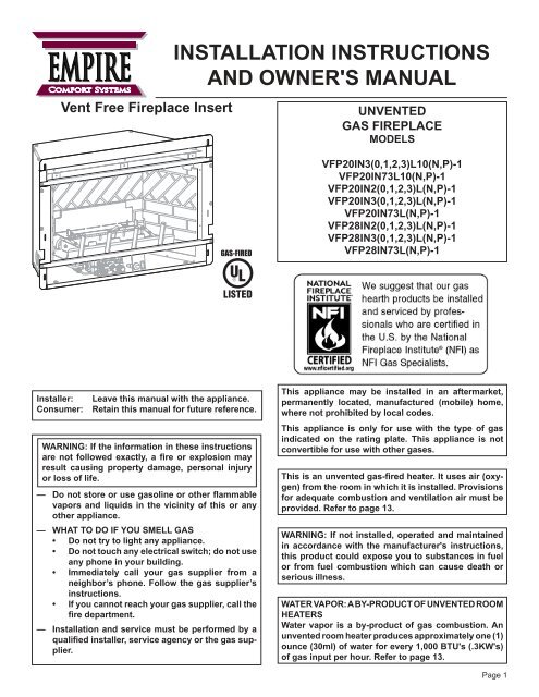
<strong>Vent</strong> <strong>Free</strong> <strong>Fireplace</strong> <strong>Insert</strong><br />
INSTALLATION INSTRUCTIONS<br />
AND OWNER'S MANUAL<br />
UNVENTED<br />
GAS FIREPLACE<br />
MODELS<br />
GAS-FIRED<br />
VFP20IN3(0,1,2,3)L10(N,P)-1<br />
VFP20IN73L10(N,P)-1<br />
VFP20IN2(0,1,2,3)L(N,P)-1<br />
VFP20IN3(0,1,2,3)L(N,P)-1<br />
VFP20IN73L(N,P)-1<br />
VFP28IN2(0,1,2,3)L(N,P)-1<br />
VFP28IN3(0,1,2,3)L(N,P)-1<br />
VFP28IN73L(N,P)-1<br />
<br />
<br />
<br />
<br />
<br />
or loss of life.<br />
<br />
<br />
<br />
<br />
indicated on the rating plate. This appliance is not<br />
<br />
<br />
vapors and liquids in the vicinity of this or any<br />
other appliance.<br />
— WHAT TO DO IF YOU SMELL GAS<br />
<br />
<br />
<br />
<br />
<br />
instructions.<br />
<br />
<br />
<br />
plier.<br />
-<br />
<br />
<br />
provided. Refer to page 13.<br />
<br />
<br />
<br />
<br />
serious illness.<br />
WATER VAPOR: A BY-PRODUCT OF UNVENTED ROOM<br />
HEATERS<br />
<br />
<br />
<br />
of gas input per hour. Refer to page 13.<br />
Page 1
TABLE OF CONTENTS<br />
SECTION<br />
PAGE<br />
IMPORTANT SAFETY INFORMATION ......................................................................................... 3<br />
SAFETY INFORMATION FOR USERS OF LP-GAS..................................................................... 4<br />
IMPORTANT INSTALLATION GUIDELINES ................................................................................. 5<br />
INTRODUCTION ........................................................................................................................... 6<br />
SPECIFICATIONS ......................................................................................................................... 7<br />
INSTALLATION IN A FIREPLACE ................................................................................................. 8<br />
FIREPLACE INSERT DIMENSIONS............................................................................................. 9<br />
BUILT-IN FIREPLACE INSTALLATION ....................................................................................... 10<br />
VFP20IN FIREPLACE WITH SURROUND DIMENSIONS ......................................................... 11<br />
VFP28IN FIREPLACE WITH SURROUND DIMENSIONS ......................................................... 12<br />
WATER VAPOR: A BY-PRODUCT OF UNVENTED ROOM HEATERS...................................... 13<br />
PROVISIONS FOR ADEQUATE COMBUSTION & VENTILATION AIR.................................13-14<br />
GAS SUPPLY .........................................................................................................................15-16<br />
CLEARANCES .......................................................................................................................16-18<br />
COMBUSTIBLE MATERIALS...................................................................................................... 19<br />
ALTERNATE ON/OFF SWITCH INSTALLATION ...................................................................20-21<br />
SURROUND PANEL INSTALLATION.......................................................................................... 22<br />
BLOWER ACCESSORY INFORMATION .................................................................................... 23<br />
VFP20IN LOG PLACEMENT....................................................................................................... 24<br />
VFP20IN EMBER PLACEMENT PHOTOS ................................................................................. 25<br />
VFP28IN LOG PLACEMENT....................................................................................................... 26<br />
VFP28IN EMBER PLACEMENT PHOTOS ................................................................................. 27<br />
HYDRAULIC THERMOSTAT LIGHTING INSTRUCTIONS......................................................... 28<br />
MILLIVOLT CONTROL VALVE LIGHTING INSTRUCTIONS ...................................................... 29<br />
10,000 BTU MILLIVOLT CONTROL VALVE LIGHTING INSTRUCTIONS .................................. 30<br />
INTERMITTENT PILOT LIGHTING INSTRUCTIONS ................................................................. 31<br />
OPERATION INSTRUCTIONS/FLAME APPEARANCE.............................................................. 32<br />
PILOT FLAME CHARACTERISTICS .....................................................................................33-34<br />
WIRING ....................................................................................................................................... 35<br />
MAINTENANCE........................................................................................................................... 35<br />
TROUBLESHOOTING SYMPTOMS - POSSIBLE CAUSES AND CORRECTIONS .................. 36<br />
IPI ELECTRONIC SYSTEM OPERATING INSTRUCTIONS....................................................... 37<br />
IPI ELECTRONIC SYSTEM WIRING DIAGRAM ........................................................................ 38<br />
INTERMITTENT CONTROL SYSTEM TROUBLESHOOTING ................................................... 39<br />
INTERMITTENT CONTROL SYSTEM TROUBLESHOOTING ..............................................40-41<br />
VFP20IN PARTS LIST................................................................................................................. 42<br />
VFP20IN PARTS VIEW ............................................................................................................... 43<br />
VFP28IN PARTS LIST................................................................................................................. 44<br />
VFP28IN PARTS VIEW ............................................................................................................... 45<br />
LOGS PARTS LISTS & PARTS VIEWS ...................................................................................... 46<br />
MASTER PARTS DISTRIBUTOR LIST ....................................................................................... 47<br />
HOW TO ORDER REPAIR PARTS ............................................................................................. 47<br />
DECORATIVE ACCESSORIES................................................................................................... 48<br />
SURROUND FRONTS ...........................................................................................................49-50<br />
WARRANTY TERMS................................................................................................................... 51<br />
Page 2<br />
29829-2-1012
IMPORTANT SAFETY INFORMATION<br />
<br />
<br />
<br />
<br />
<br />
<br />
<br />
<br />
<br />
<br />
<br />
<br />
<br />
<br />
<br />
<br />
<br />
<br />
<br />
<br />
or clothing ignition.<br />
<br />
<br />
<br />
near the appliance.<br />
QUALIFIED<br />
SERVICE PERSON. <br />
<br />
<br />
<br />
<br />
<br />
clean.<br />
<br />
<br />
<br />
<br />
<br />
<br />
<br />
<br />
during operation.<br />
<br />
<br />
<br />
<br />
<br />
<br />
<br />
<br />
<br />
<br />
<br />
<br />
<br />
<br />
period.<br />
<br />
location of the heater and annual cleaning are necessary to<br />
<br />
<br />
<br />
installation.<br />
<br />
<br />
patterns.<br />
<br />
<br />
heater.<br />
<br />
<br />
<br />
<br />
instructions.<br />
<br />
<br />
liquids.<br />
<br />
<br />
<br />
WARNING<br />
<br />
ous<br />
gas.<br />
Do not install heater until all necessary provisions are<br />
-<br />
<br />
<br />
of instructions, refer to the National Fuel Gas Code, ANSI<br />
<br />
<br />
PILOT LIGHT SAFETY SYSTEM<br />
designed to turn off the heater if not enough fresh air is<br />
<br />
DO NOT TAMPER WITH PILOT LIGHT SAFETY SYS-<br />
TEM!<br />
If heater shuts off, do not relight until you provide fresh air.<br />
<br />
<br />
<br />
DEATH.<br />
<br />
headache, dizziness and/or nausea. If you have these signs,<br />
Get fresh air at once! Have<br />
heater serviced.<br />
<br />
<br />
<br />
others.<br />
<br />
its location. If this heater is installed in a structure having a high<br />
<br />
<br />
<br />
<br />
<br />
<br />
29829-2-1012 Page 3
SAFETY INFORMATION FOR USERS OF LP-GAS<br />
<br />
<br />
-<br />
<br />
<br />
<br />
<br />
<br />
<br />
contact your gas supplier.<br />
<br />
<br />
<br />
<br />
LP-GAS WARNING ODOR<br />
<br />
<br />
<br />
phone. Do not do anything that could ignite the gas.<br />
<br />
that IMMEDIATELY.<br />
<br />
<br />
as basements. When you have reason to suspect a gas leak,<br />
keep out of basements and other low areas. Stay out until<br />
<br />
<br />
<br />
<br />
<br />
continue to smell gas, do not turn on the gas again. Do not<br />
re-enter the building, vehicle, trailer, or area.<br />
<br />
gas. Have them air out the area before you return. Properly<br />
trained LP-Gas service people should repair the leak, then<br />
check and relight the gas appliance for you.<br />
<br />
<br />
Smoking can decrease your<br />
ability to smell. Being around an odor for a time can affect your<br />
sensitivity or ability to detect that odor. Sometimes other odors in<br />
the area mask the gas odor. People may not smell the gas odor<br />
or their minds are on something else. Thinking about smelling a<br />
gas odor can make it easier to smell.<br />
<br />
For example, if there is an underground leak, the<br />
<br />
in LP-Gas also are subject to oxidation. This fading can occur if<br />
there is rust inside the storage tank or in iron gas pipes.<br />
NO ODOR DETECTED - ODOR FADE<br />
The odorant in escaped gas can adsorb or absorb onto or into walls,<br />
masonry and other materials and fabrics in a room. That will take<br />
some of the odorant out of the gas, reducing its odor intensity.<br />
LP-Gas may stratify in a closed area, and the odor intensity could<br />
vary at different levels. Since it is heavier than air, there may be<br />
more odor at lower levels. Always be sensitive to the slightest gas<br />
odor. If you detect any odor, treat it as a serious leak. Immediately<br />
go into action as instructed earlier.<br />
<br />
<br />
<br />
<br />
Learn to recognize the odor of LP-gas. Your local LP-Gas<br />
Dealer can give you a "Scratch and Sniff" pamphlet. Use it to<br />
<br />
your LP-Gas has a weak or abnormal odor, call your LP-Gas<br />
Dealer.<br />
<br />
or make adjustments to appliances on the LP-Gas system. If<br />
<br />
prior to and while lighting pilot lights or performing service or<br />
making adjustments.<br />
<br />
smell that can cover up the LP-Gas odor. Do not try to light<br />
pilot lights, perform service, or make adjustments in an area<br />
where the conditions are such that you may not detect the<br />
odor if there has been a leak of LP-Gas.<br />
<br />
new cylinders and tanks, is possible. Therefore, people should<br />
be particularly alert and careful when new tanks or cylinders<br />
are placed in service. Odor fade can occur in new tanks, or<br />
<br />
<br />
out of service for a time may develop internal rust which will<br />
SOME POINTS TO REMEMBER<br />
<br />
<br />
cause odor fade. If such conditions are suspected to exist,<br />
a periodic sniff test of the gas is advisable. If you have any<br />
LP-gas dealer. A<br />
periodic sniff test of the LP<br />
under any condition.<br />
<br />
think you should, assume you have a leak. Then take the same<br />
immediate action recommended above for the occasion when<br />
you do detect the odorized LP-Gas.<br />
der<br />
no vapor pressure), turn the tank valve off immediately.<br />
If the container valve is left on, the container may draw in<br />
<br />
occurs, some new internal rusting could occur. If the valve is<br />
left open, then treat the container as a new tank. Always be<br />
sure your container is under vapor pressure by turning it off<br />
at the container before it goes completely empty or having it<br />
<br />
Page 4<br />
29829-2-1012
IMPORTANT INSTALLATION GUIDELINES<br />
<br />
Log placement is critical to proper burner performance. Logs must<br />
be correctly positioned onto the burner. The photos in this manual<br />
show the proper pinned position for logs on this set. Owners need<br />
to be shown proper log placement and instructed not to move the<br />
logs.<br />
<br />
the photos. Malformed logs or logs with sloppy pin holes must be<br />
replaced.<br />
<br />
Rock wool can be added to burners for a glowing ember effect.<br />
It must be positioned only on the front portion of the burner. The<br />
photos in this manual show the proper placement of rock wool.<br />
Decorative lava rock or small wood pieces should never be placed<br />
<br />
<br />
<br />
<br />
primary air into the venturi tube, located on the rear of the burner,<br />
<br />
obstructions build-up around or inside the venturi. Any obstruction<br />
<br />
<br />
inlet and/or is not aligned with the venturi. Any misalignment of the<br />
<br />
<br />
<br />
Returns<br />
<br />
during the operation of vent-free logs. If the air blows directly<br />
<br />
should be turned off or redirected. Ceiling fans could be reversed<br />
<br />
be redirected. Upon installation, be aware of any cold air returns<br />
or vents in the proximity of the log set. Any draft created around<br />
<br />
create a sooting situation.<br />
WARNING: <br />
<br />
WARNING: Do not use a blower insert, heat exchanger insert or<br />
other accessory not approved for use with this heater.<br />
Candles<br />
Avoid the use of scented or decorative candles while the log set is<br />
in operation. Candles produce a residue in the air that creates a<br />
soot like substance. Burning candles while the log set is operating<br />
<br />
<br />
candles burned will determine the amount of soot produced and<br />
deposited.<br />
<br />
Properly installed and properly maintained log sets do not deposit<br />
soot on the logs. If users see soot appear on a log, call for service.<br />
Do not continue to operate the log set.<br />
29829-2-1012 Page 5
INTRODUCTION<br />
Instructions to Installer<br />
1. Installer must leave instruction manual with owner after<br />
installation.<br />
<br />
<br />
with unvented room heater.<br />
3. Installer should show owner how to start and operate unvented<br />
room heater.<br />
Always consult your local Building Department regarding regulations,<br />
codes or ordinances which apply to the installation of an unvented<br />
room heater.<br />
This appliance may be installed in an aftermarket* manufactured<br />
<br />
*Aftermarket: Completion of sale, not for purpose of resale, from<br />
the manufacturer.<br />
This appliance is only for use with the type of gas indicated on the<br />
rating plate. This appliance is not convertible for use with other<br />
gases.<br />
WARNING: ANY CHANGE TO THIS HEATER OR ITS<br />
CONTROLS CAN BE DANGEROUS.<br />
<br />
<br />
<br />
<br />
<br />
Room Heater and should be installed according to these instructions.<br />
Any alteration of the original design, installed other than as<br />
<br />
<br />
<br />
VFP28IN3 and VFP20IN3 Series Only<br />
<br />
When you ignite the pilot, the thermocouple produces millivolts<br />
<br />
After 30 seconds to 1 minute time period you can release the gas<br />
<br />
<br />
gas control knob from the PILOT position to the ON position. This<br />
<br />
<br />
<br />
All correspondence should refer to complete Model Number, Serial<br />
Number and type of gas.<br />
<br />
<br />
<br />
Notice: <br />
smoke will occur. To prevent triggering of smoke alarms, ventilate<br />
the room in which the unit is installed.<br />
Installation on Rugs and Tile<br />
If this appliance is installed directly on carpeting, tile or other<br />
<br />
be installed on a metal or wood panel extending the full width and<br />
depth of the appliance.<br />
<br />
used on wood stoves. The protection is for rugs that are extremely<br />
thick and light colored tile.<br />
Solid-fuels shall not be burned in a masonry or UL 127 factory-<br />
<br />
<br />
<br />
<br />
<br />
<br />
person or through a representative is engaged in and is responsible for<br />
<br />
<br />
<br />
<br />
State of Massachusetts: The installation must be made by<br />
<br />
Massachusetts.<br />
<br />
room heaters shall provide to each purchaser a copy of 527<br />
CMR 30 upon sale of the unit.<br />
In the Sate of Massachusetts, unvented propane and natural<br />
<br />
bathrooms.<br />
The installation must conform with local codes or, in the absence<br />
of local codes, with the National Fuel Gas Code, ANSI Z223.1.*<br />
*Available from the American National Standards Institute, Inc. 1430<br />
Broadway, New York, N.Y. 10018.<br />
High Altitudes<br />
<br />
<br />
sea level. Contact the manufacturer or your gas company before<br />
<br />
Well Head Gas Installations<br />
Some natural gas utilities use "well head" gas. This may affect the<br />
Btu output of the unit. Contact the gas company for the heating value.<br />
Contact the manufacturer or your gas company before changing<br />
<br />
WARNING: <br />
propane) gas. Field conversion is not permitted.<br />
Page 6<br />
29829-2-1012
SPECIFICATIONS<br />
VFP28IN(3,7)*L LP NAT<br />
Input Btu/hr Maximum 28,000 28,000<br />
Btu/hr Minimum 20,000 20,000<br />
#52 #38<br />
Air Shutter Opening Full Open 1/8”<br />
VFP28IN2*L LP NAT<br />
Input Btu/hr Maximum 28,000 28,000<br />
Btu/hr Minimum 20,000 20,000<br />
#53 #42<br />
Air Shutter Opening Full Open 1/8"<br />
VFP20IN2*L LP NAT<br />
Input Btu/hr Maximum 20,000 20,000<br />
Btu/hr Minimum 10,000 10,000<br />
#55 #43<br />
Air Shutter Opening Full Open 1/8"<br />
VFP20IN(3,7)*L LP NAT<br />
Input Btu/hr Maximum 20,000 20,000<br />
Btu/hr Minimum 15,000 14,000<br />
#55 #49<br />
Air Shutter Opening Full Open 1/8"<br />
VFP20IN(3,7)*L10 LP NAT<br />
Input Btu/hr Maximum 10,000 10,000<br />
Btu/hr Minimum 10,000 10,000<br />
#64 #53<br />
Air Shutter Opening Full Open 1/8"<br />
<br />
S256BL<br />
S336BL<br />
S253BL<br />
S333BL<br />
SC256BL<br />
SC336BL<br />
Accessories for VFP(20,28)IN3 (Millivolt) Models<br />
Description<br />
Accessories<br />
FRBC Battery Operated Remote Control<br />
FRBTC Battery Operated Remote Control with<br />
Thermostat<br />
FRBTP Battery Operated Programmable Remote<br />
Control<br />
FREC Electric Remote Control<br />
FWS-1 Wall Switch<br />
TRW <br />
TMV<br />
Wall Thermostat, Millivolt - Reed Switch<br />
<br />
<br />
DF20GBL<br />
DF20MBL<br />
DF20LBL<br />
Description<br />
<br />
6" Wide, black for use on VFP20IN<br />
6" Wide, black for use on VFP28IN<br />
3" Wide, black for use on VFP20IN<br />
3" Wide, black for use on VFP28IN<br />
Traditional Cast Iron<br />
6" Wide, black for use on VFP20IN<br />
6" Wide, black for use on VFP28IN<br />
Description<br />
Decorative Front, Tempered Glass, Black<br />
Decorative Front, Metal Frame, Black<br />
cludes<br />
6 x 6 Surround)<br />
<br />
Surround Kit Description<br />
DF28GBL Decorative Front, Tempered Glass, Black<br />
DF28MBL Decorative Front, Metal Frame, Black<br />
DF28LBL cludes<br />
6 x 6 Surround)<br />
29829-2-1012 Page 7
INSTALLATION IN A FIREPLACE<br />
1. Before beginning, remove door and log package from<br />
unit. Also check to make sure there is no hidden damage<br />
to the unit. Take a minute and plan out the gas and<br />
<br />
<br />
<br />
Figure 2 fractory),<br />
glass doors, screen rails, screen mesh and<br />
log grates can be removed from a <br />
-<br />
<br />
<br />
<br />
Do not obstruct the lower louver of the insert. The origi-<br />
dition.<br />
<br />
to facilitate the installation of the insert. The side walls<br />
<br />
<br />
<br />
place<br />
cannot be returned to solid fuel in this condition.<br />
5. The insert surround is tested and approved with this<br />
gas insert and may cover existing air circulation vents<br />
<br />
the surround does not cover the entire ventilation grill<br />
surface, the exposed grill area should be left open.<br />
-<br />
<br />
<br />
<br />
<br />
<br />
<br />
-<br />
<br />
<br />
-<br />
<br />
See "Positioning, Leveling and Securing <strong>Insert</strong>" below.<br />
6. Install the insert without the surround panels attached<br />
and make all gas venting and electrical connections.<br />
cess<br />
holes provided, an access hole of 1 1/2” di-<br />
<br />
<br />
<br />
<br />
<br />
place<br />
has been installed with all the gas and electrical<br />
tions<br />
included with the surround panel kit.<br />
-<br />
<br />
Positioning, Leveling and Securing <strong>Insert</strong><br />
1. Place the insert into position<br />
Note: <br />
panels) should be set at approximately 1" in front of<br />
<br />
2. Level the insert from side to side and front to back.<br />
3. If necessary, use the leveling bolts included in the instruction<br />
pack. Screw the legs into the nuts installed in the bottom<br />
of the insert. Turn legs in until insert is level.<br />
NOTE: The best way to access the leveling bolt loca-<br />
<br />
Page 8<br />
29829-2-1012
FIREPLACE INSERT DIMENSIONS<br />
<br />
to determine:<br />
<br />
<br />
F<br />
<br />
<br />
<br />
<br />
switch or remote control - are desired.<br />
<br />
1 Amp)<br />
-<br />
<br />
E<br />
D<br />
C<br />
A<br />
B<br />
VF FIREPLACE INSERT DIMENSIONS<br />
MODEL A B C D E F<br />
VFP20IN 19 3/4" 18 5/16" 13 3/4" 29 1/4" 25 1/2" 16 1/8"<br />
VFP28IN 22 3/4" 21 5/16" 15 3/16" 32 1/4" 28 1/2" 17 7/8"<br />
Figure 1<br />
<br />
MINIMUM FIREPLACE OPENING DIMENSIONS<br />
MODEL HEIGHT<br />
A<br />
FRONT<br />
WIDTH B<br />
DEPTH<br />
C<br />
REAR<br />
WIDTH D<br />
VFP20IN 18 1/2" 26 3/4" * 12 3/4" 15 3/4"<br />
VFP28IN 21 1/2" 30 3/4" * 14 1/4" 19"<br />
Notice <br />
<br />
<br />
not intended to be used for framing dimensions.<br />
C<br />
A<br />
D<br />
*Notice: Front Width B is the minimum and maximum dimension.<br />
B<br />
Figure 2<br />
29829-2-1012 Page 9
BUILT-IN FIREPLACE INSTALLATION<br />
<br />
to determine where the unit is to be installed and whether<br />
optional accessories are desired. Gas supply piping should<br />
also be planned at this time.<br />
<br />
<br />
2. A raised platform of combustible or non-combustible<br />
material.<br />
<br />
all four perimeter edges on the bottom of the unit.<br />
<br />
This unit is designed to be installed in a zero-clearance enclosure.<br />
This means the combustible material can come in<br />
<br />
Rough Opening for Installing in Wall<br />
<br />
<br />
installed on a metal or wood panel extending the full width<br />
and depth of the unit.<br />
At this point, you should have decided what components<br />
<br />
be located. If this has not been done, stop and consult your<br />
dealer for assistance with this planning.<br />
Built-In <strong>Fireplace</strong> Installation<br />
<br />
<br />
<br />
<br />
10 through 12. Follow the instructions below to install the<br />
<br />
Frame in rough opening. Use dimensions show in Figure 3<br />
for a conventional rough opening. Use dimensions shown in<br />
Figure 4 for corner rough opening. Be sure to provide gas<br />
sembly.<br />
1. Gas line connections must be made at this time. When<br />
facing the appliance, the gas supply will enter on the<br />
right-hand side. See "Gas Supply" pages 15 to 16.<br />
<br />
<br />
<strong>Insert</strong>" on Page 8.<br />
<br />
<br />
5. If used, the surround panel assembly is installed after<br />
<br />
electrical connection completed. See Page 22. Refer to<br />
instructions included with the surround panel kit.<br />
<br />
Rough Opening for Installing in Corner<br />
INSTALLATION<br />
FLUSH<br />
INSTALLATION PROJECTED<br />
D<br />
1” TO 6” FROM BACK<br />
25mm TO 152mm<br />
ELECTRICAL RECEPTACLE<br />
C<br />
25 5/8”<br />
650.9mm<br />
C<br />
7 1/2” (190.5mm)<br />
GAS SUPPLY<br />
B<br />
Figure 3<br />
VFP20IN<br />
VFP28IN<br />
B<br />
51 1/4” (1301.8mm)<br />
Figure 4<br />
A B C D<br />
13 3/4"<br />
<br />
16 3/4"<br />
<br />
27 3/4"<br />
<br />
30 1/2"<br />
<br />
18 1/2"<br />
<br />
22 1/2"<br />
<br />
36 1/4"<br />
<br />
36 1/4"<br />
<br />
Page 10<br />
29829-2-1012
VFP20IN FIREPLACE WITH SURROUND DIMENSIONS<br />
40 1/2”<br />
2 3/8”<br />
26 1/2”<br />
DF20MBL<br />
40”<br />
1 3/4”<br />
255/8 ”<br />
15/16 ”<br />
DF20LBL<br />
34”<br />
4 1/4”<br />
25”<br />
11 1/2”<br />
20 1/2”<br />
DF20GBL<br />
29829-2-1012 Page 11
VFP28IN FIREPLACE WITH SURROUND DIMENSIONS<br />
43 1/2”<br />
2 3/8”<br />
29 1/2”<br />
DF28MBL<br />
43”<br />
1 3/4”<br />
28 5/8”<br />
15/16”<br />
DF28LBL<br />
37”<br />
4 1/4”<br />
28”<br />
14 1/2”<br />
23 1/2”<br />
DF28GBL<br />
Page 12<br />
29829-2-1012
WATER VAPOR: A BY-PRODUCT OF UNVENTED ROOM HEATERS<br />
Water vapor is a by-product of gas combustion. An unvented room<br />
<br />
<br />
<br />
<br />
supplemental heat applications, the water vapor does not create a<br />
problem. In most applications, the water vapor enhances the low<br />
humidity atmosphere experienced during cold weather.<br />
The following steps will help insure that water vapor does not<br />
become a problem.<br />
1. Be sure the heater is sized properly for the application, including<br />
ample combustion air and circulation air.<br />
<br />
help lower the water vapor content of the air.<br />
3. Do not use an unvented room heater as the primary heat<br />
source.<br />
PROVISIONS FOR ADEQUATE COMBUSTION & VENTILATION AIR<br />
<br />
<br />
combustion and ventilation air.<br />
<br />
1,000 Btuh of the combined input rates of all appliances drawing<br />
<br />
<br />
which supply heated air to areas outside the space must draw return<br />
air from outside the space through tightly sealed return air ducts. A<br />
tion<br />
air. One opening must be within 12 inches of the ceiling and<br />
<br />
of these openings is determined by whether inside or outside air is<br />
used to support combustion, the method by which the air is brought<br />
<br />
of all appliances in the space.<br />
Unusually Tight Construction<br />
The air that leaks around doors and windows may provide enough<br />
fresh air for combustion and ventilation. However, in buildings of<br />
unusually tight construction, you must provide additional fresh air.<br />
<br />
<br />
a. Walls and ceilings exposed to the outside atmosphere have<br />
a continuous water vapor retarder with a rating of one perm<br />
or less with openings gasketed or sealed, and<br />
b. Weather-stripping has been added on openable windows<br />
and doors, and<br />
c. Caulking or sealants are applied to areas such as joints<br />
around window and door frames, between sole plates and<br />
<br />
penetrations for plumbing, electrical, and gas lines, and at<br />
other openings.<br />
If your home meets all of the three criteria above, you must provide<br />
additional fresh air. See page<br />
14.<br />
<br />
<br />
space.<br />
Space: Includes the room in which you will install heater plus any<br />
adjoining rooms with doorless passageways or ventilation grills<br />
between the rooms.<br />
<br />
Length x Width x Height =<br />
<br />
space)<br />
Example:<br />
<br />
If additional ventilation to adjoining room is supplied with grills<br />
or openings, add the volume of these rooms to the total volume<br />
of the space.<br />
2. Divide the space volume by 50 cubic feet to determine the<br />
maximum BTU/Hr the space can support.<br />
<br />
BTU/Hr the space can support)<br />
Example:<br />
<br />
3. Add the BTU/Hr of all fuel burning appliances in the space.<br />
<strong>Vent</strong>-free heater<br />
BTU/Hr<br />
Gas water heater<br />
BTU/Hr<br />
Gas furnace<br />
BTU/Hr<br />
<strong>Vent</strong>ed gas heater BTU/Hr<br />
BTU/Hr<br />
Other gas appliances*+ BTU/Hr<br />
Total = BTU/Hr<br />
Example: <strong>Vent</strong>ed gas heater 20,000 BTU/Hr<br />
<strong>Vent</strong>-free heater + 18,000 BTU/Hr<br />
Total = 38,000 BTU/Hr<br />
*Do not include direct-vent gas appliances. Direct vent draws<br />
combustion air from the outdoors and vents to the outdoors.<br />
4. Compare the maximum BTU/Hr the space can support with the<br />
actual amount of BTU/Hr used.<br />
<br />
<br />
Example:<br />
<br />
<br />
Warning: If the area in which the heater may be operated is smaller<br />
<br />
<br />
ventilation air by one of the methods described in the National<br />
Fuel Gas Code, ANSI Z223.1/NFPA 54, Air for Combustion and<br />
<strong>Vent</strong>ilation, or applicable local codes.<br />
29829-2-1012 Page 13
PROVISIONS FOR ADEQUATE COMBUSTION & VENTILATION AIR (continued)<br />
<br />
actual BTU/Hr used is more than the maximum BTU/HR the space<br />
can support. You must provide additional fresh air. Your options<br />
are as follows:<br />
A. Rework worksheet, adding the space of an adjoining room. If<br />
<br />
to adjoining room or add ventilation grills between rooms. See<br />
<br />
B. <strong>Vent</strong> room directly to the outdoors. See <br />
Outdoors.<br />
C. Install a lower BTU/Hr heater, if lower BTU/Hr size makes room<br />
<br />
If the actual BTU/Hr used is less than the maximum BTU/Hr the<br />
<br />
no additional fresh air ventilation.<br />
WARNING<br />
<br />
space.<br />
<br />
Provide extra fresh air by using ventilation grills or ducts. You must<br />
provide two permanent openings: one within 12" of the ceiling and<br />
<br />
or spaces open to the outdoors. These spaces include attics and<br />
crawl spaces. In most cases for direct communication with the<br />
outdoors or direct communication through a vertical duct a free<br />
<br />
rating for each grill. If a horizontal duct is used, a grill free area or<br />
<br />
2,000 BTU/Hr for each grill. Follow the National Fuel Code ANSI<br />
Z223.1/NFPA54, Air for Combustion and <strong>Vent</strong>ilation<br />
size of ventilation grills or ducts.<br />
IMPORTANT: Do not provide openings for inlet or outlet air into attic<br />
if attic has a thermostat-controlled power vent. Heated air entering<br />
the attic will activate the power vent.<br />
<strong>Vent</strong>ilation Air<br />
<br />
<br />
<br />
permanent openings: one within 12" of the ceiling and one within<br />
<br />
1 and 2, Figure 5). You can also remove door into adjoining room<br />
<br />
<br />
<br />
<br />
A1<br />
A2<br />
Figure 5<br />
WARNING<br />
<br />
<br />
.<br />
B1<br />
A1 x B1 = C1<br />
A2 x B2 = C2<br />
<br />
<br />
<br />
2 2 2<br />
2 2 2<br />
2 2 = 30in 2<br />
B2<br />
Figure 7<br />
Page 14<br />
29829-2-1012
GAS SUPPLY<br />
The gas pipeline can be brought in through the right or left side of<br />
the appliance. The insert has a Flexline with shutoff valve located on<br />
the right side when facing the unit. See Figures 8 and 9. Consult<br />
the current National Fuel Gas Code, ANSI Z223.1 CAN/CGA-B149<br />
<br />
Pipe Length<br />
0-10ft<br />
0-3m<br />
11-40ft<br />
4-12m<br />
41-100ft<br />
13-30m<br />
101-150ft<br />
31-46m<br />
<br />
Schedule 40 Pipe<br />
<br />
<br />
<br />
Nat. L.P. Nat. L.P.<br />
1/2"<br />
12.7mm<br />
1/2"<br />
12.7mm<br />
1/2"<br />
12.7mm<br />
3/4"<br />
19mm<br />
3/8"<br />
9.5mm<br />
1/2"<br />
12.7mm<br />
1/2"<br />
12.7mm<br />
1/2"<br />
12.7mm<br />
1/2"<br />
12.7mm<br />
5/8"<br />
15.9mm<br />
3/4"<br />
19mm<br />
7/8"<br />
22.2mm<br />
3/8"<br />
9.5mm<br />
1/2"<br />
12.7mm<br />
1/2"<br />
12.7mm<br />
3/4"<br />
1.9 mm<br />
Note:<br />
local codes allow copper tubing or galvanized.<br />
Note: Since some municipalities have additional local codes, it is<br />
always best to consult your local authority and installation code.<br />
The use of the following gas connectors is recommended:<br />
— ANS Z21.24 Appliance Connectors of Corrugated Metal Tubing<br />
and Fittings.<br />
— ANS Z21.45 Assembled Flexible Appliance Connectors of Other<br />
Than All-Metal Construction<br />
The above connectors may be used if acceptable by the authority<br />
<br />
appliance connector cannot exceed three feet in length.<br />
<br />
Each appliance should have its own manual gas cock.<br />
A manual main gas cock should be located in the vicinity of the unit.<br />
<br />
contact your local authorized installer for installation or relocation.<br />
Compounds used on threaded joints of gas piping shall be resistant<br />
<br />
checked for leaks by the installer. This should be done with a soap<br />
solution watching for bubbles on all exposed connections, and if<br />
unexposed, a pressure test should be made.<br />
<br />
<br />
<br />
<br />
NOTE: <br />
type pressure test point, therefore it is not necessary to provide a<br />
1/8" test point up stream of the control.<br />
<br />
<br />
from supply piping system during any pressure testing of that system<br />
<br />
The appliance must be isolated from the gas supply piping system<br />
by closing its individual manual shut off valve during any pressure<br />
<br />
<br />
Attention! If one of the procedures results in pressures in excess of<br />
<br />
in a hazardous condition.<br />
FRONT OF<br />
INSERT<br />
RIGHT SIDE OF INSERT<br />
Figure 8<br />
Figure 9<br />
GAS FLEX LINE WITH<br />
SHUTOFF VALVE<br />
(PROVIDED)<br />
29829-2-1012 Page 15
MILLIVOLT VALVES<br />
Natural gas will have a manifold pressure of approximately 3.5" w.c.<br />
for maximum input or 1.7" w.c. for minimum input at the pressure<br />
regulator outlet with the inlet pressure to the pressure regulator<br />
from a minimum of 4.5" w.c. for the purpose of input adjustment to<br />
a maximum of 10.5" w.c.<br />
Propane gas will have a manifold pressure approximately 10.0"w.c.<br />
<br />
pressure regulator outlet with the inlet pressure to the pressure<br />
regulator from a minimum of 11.0"w.c. for the purpose of input<br />
adjustment to a maximum of 13.0"w.c.<br />
HYDRAULIC THERMOSTAT VALVES<br />
Natural gas will have a manifold pressure of approximately 6.0"<br />
w.c. at the pressure regulator outlet with the inlet pressure to the<br />
pressure regulator from a minimum of 7.0" w.c. for the purpose of<br />
input adjustment to a maximum of 10.5" w.c.<br />
Propane gas will have a manifold pressure approximately 10.0"w.c.<br />
at the pressure regulator outlet with the inlet pressure to the pressure<br />
regulator from a minimum of 11.0"w.c. for the purpose of input<br />
adjustment to a maximum of 13.0"w.c.<br />
A test gage connection is located downstream of the gas appliance<br />
pressure regulator for measuring gas pressure. The connection is<br />
a 1/8 inch N.P.T. plugged tapping.<br />
Millivolt Control Valve<br />
The valve regulator controls the burner pressure which should be<br />
checked at the pressure test point. Turn captured screw counter<br />
clockwise 2 or 3 turns and then place tubing to pressure gauge over<br />
<br />
<br />
<br />
<br />
No greeting cards, stockings or ornamentation of any type<br />
<br />
heat can ignite combustibles.<br />
CLEARANCES<br />
8”<br />
MINIMUM CLEARANCE<br />
TO PERPENDICULAR<br />
COMBUSTIBLE SIDE-WALL<br />
Figure 10<br />
Page 16<br />
29829-2-1012
FINISHED WALL<br />
FLAT MANTEL SHELF<br />
12”<br />
10”<br />
8”<br />
6”<br />
2”<br />
4”<br />
15”<br />
17”<br />
19”<br />
21”<br />
11”<br />
13”<br />
VFP20 Series Figure 11<br />
FINISHED WALL<br />
FLAT MANTEL SHELF<br />
12”<br />
10”<br />
8”<br />
6”<br />
2”<br />
4”<br />
20”<br />
22”<br />
24”<br />
26”<br />
16”<br />
18”<br />
VFP28 Series Figure 12<br />
29829-2-1012 Page 17
CEILING<br />
NO MANTEL<br />
26” MIN.<br />
TOP OF FIREPLACE OPENING<br />
FLOOR<br />
Surround Clearances Figure 13<br />
CEILING<br />
NO MANTEL<br />
26” MIN.<br />
TOP OF FIREPLACE OPENING<br />
FLOOR<br />
Glass Front Clearances Figure 14<br />
Page 18<br />
29829-2-1012
COMBUSTIBLE MATERIALS<br />
Do not attach combustible material to the mantel of your<br />
<br />
No greeting cards, stockings or ornamentation of any type<br />
<br />
<br />
Figure 15<br />
<br />
29829-2-1012 Page 19
ALTERNATE ON/OFF SWITCH INSTALLATION<br />
WIRING THE FIREPLACE<br />
<br />
electrician.<br />
CAUTION: DISCONNECT REMOTE CONTROLS IF YOU<br />
ARE ABSENT FOR EXTENDED TIME PERIODS. THIS<br />
WILL PREVENT ACCIDENTAL FIREPLACE OPERA-<br />
TION.<br />
<br />
<br />
An ON/OFF switch and wire assembly are provided. They<br />
are included in the instruction packet.<br />
Do not cut wire or insulation on metal edges.<br />
Note: Refer to surround panel installation section on<br />
<br />
Standard Surrounds DF(20,28)LBL<br />
1. Find the coiled low voltage wire assembly and ON/OFF<br />
switch located in the instruction packet.<br />
<br />
terminals on the front terminal block of the gas valve.<br />
See Figure 22.<br />
3. Run the low voltage alternate switch wires up the back<br />
of the right or left surround panel. Then secure the wires<br />
with wire clips provided. See Figure 17.<br />
Right Side Instalation Left Side Instalation<br />
Page 20<br />
ON/OFF<br />
SWITCH<br />
ASSEMBLY<br />
WIRING FROM<br />
MILLIVOLT GAS<br />
VALVE<br />
ON/OFF<br />
SWITCH<br />
ASSEMBLY<br />
Figure 17<br />
<br />
<br />
4. Remove the switch knockout on the side surround panel,<br />
then install the ON/OFF switch.<br />
5. Connect the low voltage wires from the gas valve to the<br />
ON/OFF switch.<br />
6. Attach the surround panel assembly to the insert. Place<br />
the surround panel assembly against the face of the insert<br />
and align the lower retaining tabs with the notches<br />
on the insert sides. Lift the surround panel assembly<br />
-<br />
<br />
surround panel assembly to the insert without screws.<br />
Traditional Cast Iron Surrounds<br />
1. Find the coiled low voltage wire assembly and ON/OFF<br />
switch located in the instruction packet.<br />
<br />
terminals on the front terminal block of the gas valve.<br />
See Figure 19.<br />
3. Run the low voltage alternate switch wires up the back<br />
of the right or left cast surround leg. Then secure them<br />
with the wire clips provided.<br />
4. Install the switch bracket with screws as shown in Figure<br />
18 to the back of the cast surround leg.<br />
Figure 18<br />
-<br />
<br />
5. Install ON/OFF switch, and connect low-voltage wires<br />
from gas valve.<br />
6. Attach cast surround panel assembly to the insert.<br />
Place the cast surround assembly against the face of<br />
the insert and align the lower retaining tabs with the<br />
notches on the insert sides. Lift the cast surround as-<br />
<br />
cures<br />
the cast surround assembly to the insert without<br />
screws.<br />
WIRES FROM ON/OFF<br />
SWITCH INSTALLED IN<br />
LEFT OR RIGHT SIDE<br />
SURROUND PANELS<br />
TH/TP<br />
TP<br />
TH<br />
NOTE: TO OPERATE INSERT WITH SIDE PANEL<br />
ON/OFF SWITCH, BE SURE TO PLACE THE MAIN<br />
SWITCH (TO THE RIGHT SIDE OF GAS VALVE) TO “ OFF”<br />
POSITION<br />
Figure 19<br />
29829-2-1012
ALTERNATE ON/OFF SWITCH INSTALLATION<br />
WIRING THE FIREPLACE<br />
WARNING<br />
cian.<br />
WARNING<br />
DISCONNECT REMOTE CONTROLS IF YOU ARE ABSENT<br />
FOR EXTENDED TIME PERIODS. THIS WILL PREVENT AC-<br />
CIDENTAL FIREPLACE OPERATION.<br />
<br />
<br />
An ON/OFF switch and wire assembly are provided. They are included<br />
in the instruction packet.<br />
Do not cut wire or insulation on metal edges.<br />
Notice: Refer to surround panel installation section in the<br />
-<br />
<br />
DF(20,28)MBL<br />
1. Find the coiled low voltage wire assembly and ON/OFF switch<br />
located in the instruction packet.<br />
nals<br />
on the front terminal block of the gas valve. See Figure<br />
21.<br />
3. Run the low voltage alternate switch wires up the back of the<br />
right or left surround panel. Then secure the wires with wire<br />
clips provided. See Figure 20.<br />
6. Attach the surround panel assembly to the insert. Place the<br />
surround panel assembly against the face of the insert and<br />
align the lower retaining tabs with the notches on the insert<br />
sides. Lift the surround panel assembly slightly until the bot-<br />
<br />
on the insert. This secures the surround panel assembly to<br />
the insert without screws.<br />
WIRES FROM ON/OFF<br />
SWITCH INSTALLED IN<br />
LEFT OR RIGHT SIDE<br />
SURROUND PANELS<br />
TH/TP<br />
TP<br />
TH<br />
NOTE: TO OPERATE INSERT WITH SIDE PANEL<br />
ON/OFF SWITCH, BE SURE TO PLACE THE MAIN<br />
SWITCH (TO THE RIGHT SIDE OF GAS VALVE) TO “ OFF”<br />
POSITION<br />
Figure 21<br />
ON/OFF<br />
SWITCH<br />
WIRING FROM<br />
MILLIVOLT GAS<br />
VALVE<br />
<br />
-<br />
<br />
<br />
then install the ON/OFF switch into the switch bracket.<br />
5. Connect the low voltage wires from the gas valve to the<br />
ON/OFF switch.<br />
<br />
<br />
access to the ON/OFF switch.<br />
29829-2-1012 Page 21
SURROUND PANEL INSTALLATION<br />
INSTALLING THE TRIM SURROUNDS<br />
Combustible materials MUST NEVER overlap onto the front<br />
face.<br />
WARNING: WHEN FINISHING THE FIREPLACE IN-<br />
SERT, NEVER OBSTRUCT OR MODIFY THE AIR<br />
INLET/OUTLET LOUVERS ON THE FIREPLACE IN-<br />
SERT IN ANY MANNER.<br />
NOTE: INSTALL SURROUND PANELS<br />
SO THAT THE TOP PANEL<br />
RETURN FLANGE SLIDE’S<br />
OVER THE TOP FLANGE ON<br />
THE INSERT<br />
Figure 23<br />
ENGAGE SIDE PANEL<br />
HOOKS WITH THE<br />
NOTCHES PROVIDED ON<br />
THE SIDE FLANGES<br />
SURROUND PANEL ASSEMBLY<br />
1” Ref.<br />
Figure 22<br />
Page 22<br />
29829-2-1012
BLOWER ACCESSORY INFORMATION<br />
<br />
<br />
<br />
National Electrical Code, ANSI/NFPA No. 70.<br />
<br />
<br />
<br />
25 and the parts list on pages 42 through 45.<br />
BLOWER ASSEMBLY<br />
THE FAN CONTROL SWITCH IS<br />
CLIPPED BETWEEN THE BURNER<br />
BASE AND VALVE BRACKET<br />
BLOWER ACCESSORY<br />
Operation<br />
<br />
blower accessory that includes a fan control switch, plus a<br />
<br />
The speed control knob is located behind the lower louver<br />
at the right side of the insert.<br />
From a cold start, the temperature activated fan control<br />
switch will normally take 5-10 minutes to heat up and<br />
energize the blower. Start the blower in the "High" setting.<br />
Once the blower is energized, adjust the blower speed<br />
control as desired, then replace the lower louver.<br />
When the insert is shut off, it may take 30-40 minutes for the<br />
<br />
to shut off automatically. Note: The blower shut off times will<br />
vary on blower speed and BTU input level setting control by<br />
adjustment of the HI/LO knob located on the gas valve.<br />
<br />
Servicing or removal of the blower system must be performed<br />
<br />
If the blower assembly must be replaced, the following<br />
steps are recommended for removal:<br />
1. Turn off gas and disconnect the electrical supply.<br />
2. Remove the screen door assembly.<br />
3. Remove the log set.<br />
4. Remove the front surround panel assembly by lifting<br />
upward and outward to detach.<br />
<br />
forward on the insert.<br />
7. As the insert is moved outward, the gas line may need<br />
to be disconnected at the insert shut off valve. If so,<br />
make sure the main gas line is shut off that supplies gas<br />
to the insert.<br />
8. Once the insert is pulled out, the blower assembly can<br />
<br />
back of the insert that retains the blower base plate.<br />
9. When the screws are removed, gently pull the blower<br />
assembly outward.<br />
10. Disconnect the two ¼” wire terminals from the motor.<br />
<br />
to the base plate, and set blower aside.<br />
12. Install the replacement blower, and re-install the insert<br />
by reversing above steps.<br />
MILLIVOLT VALVE<br />
PIEZO IGNITOR<br />
REMOTE/OFF/ON SWITCH<br />
VFP28IN<br />
THE FAN CONTROL SWITCH IS<br />
CLIPPED BETWEEN THE BURNER<br />
BASE AND FIREBOX BOTTOM<br />
MILLIVOLT VALVE<br />
VFP20IN<br />
Figure 24<br />
BLOWER ASSEMBLY<br />
PIEZO IGNITOR<br />
REMOTE/OFF/ON SWITCH<br />
FAN SPEED CONTROL<br />
FAN SPEED CONTROL<br />
Figure 25<br />
29829-2-1012 Page 23
VFP20IN LOG PLACEMENT<br />
Before you begin: Do not, handle these logs with your<br />
bare hands! Always wear gloves to prevent skin irritation.<br />
After handling logs, wash your hands gently with soap and<br />
water.<br />
All Logs<br />
The positioning of the logs is critical to the safe and clean<br />
operation of this heater. Sooting and other problems may<br />
<br />
appliance.<br />
Warning: Failure to position the parts in accordance<br />
<br />
approved with this appliance may result in property<br />
damage or personal injury.<br />
PROPER INSTALLATION SEQUENCE:<br />
<br />
<br />
pan.<br />
<br />
burner pan.<br />
<br />
burner pan.<br />
4. Compare the completed log installation with the<br />
appropriate photo from page 47. Review previous steps<br />
to make any necessary adjustments.<br />
5. Log placement is completed.<br />
6. Attach log placement plate to cable holding lighting<br />
instructions for future reference.<br />
Attention: Do not use Figure 26 to order replacement logs.<br />
Refer to Page 46 Parts List and Parts View to order logs for<br />
your appropriate model number.<br />
<br />
<br />
<br />
an authorized distributor. Application of excess loose material<br />
<br />
heater.<br />
Rock wool can be added to burners for a glowing ember<br />
<br />
locations shown on Page 25. Replacement of loose material<br />
<br />
<br />
embers) may adversely affect performance of the heater.<br />
WARNING: All previously applied loose material must be<br />
removed prior to reapplication.<br />
<br />
<br />
Note: A single layer of embers is to be used when applying<br />
<br />
production embers) to the burner.<br />
2<br />
1<br />
<br />
<br />
The following WARNING applies when log set is installed<br />
onto an unvented gas burner assembly.<br />
<br />
propane) gas. Field conversion is not permitted.<br />
3<br />
Page 24<br />
29829-2-1012
VFP20IN EMBER PLACEMENT PHOTOS<br />
Do not cover any large rear ports with<br />
lose material (glowing embers).<br />
29829-2-1012 Page 25
VFP28IN LOG PLACEMENT<br />
Before you begin: Do not, handle these logs with your<br />
bare hands! Always wear gloves to prevent skin irritation.<br />
After handling logs, wash your hands gently with soap and<br />
water.<br />
All Logs<br />
The positioning of the logs is critical to the safe and clean<br />
operation of this heater. Sooting and other problems may<br />
<br />
appliance.<br />
Warning: Failure to position the parts in accordance<br />
<br />
approved with this appliance may result in property<br />
damage or personal injury.<br />
PROPER INSTALLATION SEQUENCE:<br />
(Figure 27)<br />
<br />
<br />
burner pan.<br />
<br />
burner pan.<br />
<br />
5. Compare the completed log installation with the photo on<br />
page 27. Review previous steps to make any necessary<br />
adjustments.<br />
6. Log placement is completed.<br />
7. Attach log placement plate to cable holding lighting<br />
instructions for future reference.<br />
Attention: Do not use Figure 27 to order replacement logs.<br />
Refer to Page 46 Parts List and Parts View to order logs.<br />
Rock wool can be added to burners for a glowing ember<br />
<br />
locations shown on Page 27. Replacement of loose material<br />
<br />
<br />
embers) may adversely affect performance of the heater.<br />
<br />
<br />
Note: A single layer of embers is to be used when<br />
<br />
with production embers) to the burner.<br />
2<br />
1<br />
<br />
Figure 27<br />
The following WARNING applies when log set is installed<br />
onto an unvented gas burner assembly.<br />
<br />
propane) gas. Field conversion is not permitted.<br />
4<br />
3<br />
WARNING: All previously applied loose material must<br />
be removed prior to reapplication.<br />
8. Install front frame assembly.<br />
Page 26<br />
29829-2-1012
VFP28IN EMBER PLACEMENT PHOTOS<br />
Photo 1<br />
Do not cover any large rear ports with<br />
lose material (glowing embers)<br />
Photo 2<br />
Do not cover any large front ports with<br />
lose material (glowing embers)<br />
Photo 3 Photo 4<br />
29829-2-1012 Page 27
HYDRAULIC THERMOSTAT LIGHTING INSTRUCTIONS<br />
FOR YOUR SAFETY READ BEFORE LIGHTING<br />
WARNING:<br />
<br />
<br />
<br />
<br />
B. BEFORE LIGHTING <br />
<br />
<br />
WHAT TO DO IF YOU SMELL GAS<br />
<br />
<br />
<br />
<br />
<br />
<br />
<br />
C. Use only your hand to push in or turn the gas control<br />
<br />
<br />
<br />
<br />
<br />
<br />
<br />
<br />
1. STOP! Read the safety information above.<br />
<br />
cable).<br />
4. Push in gas control knob slightly and turn clockwise<br />
to "OFF". Do not force.<br />
<br />
<br />
<br />
smell gas, go to the next step.<br />
6. Find pilot - the pilot is in front<br />
of the rear log.<br />
7. Turn gas control knob<br />
counterclockwise to<br />
"PILOT."<br />
8. Push in gas control knob all the way and hold in. Repeat-<br />
<br />
a match to light pilot). Continue to hold the control knob<br />
<br />
knob and it will pop back up. Pilot should remain lit. If it<br />
LIGHTING INSTRUCTIONS<br />
TO TURN OFF GAS TO APPLIANCE<br />
goes out, repeat steps 4 through 8.<br />
<br />
immediately call your service technician or gas<br />
supplier.<br />
<br />
the gas control knob to "OFF" and call your service<br />
technician or gas supplier.<br />
9. Attention! Gas control has an INTERLOCK latching device.<br />
When the pilot is initially lit and the safety magnet<br />
<br />
device becomes operative. If the gas control is turned to<br />
<br />
off, the pilot cannot be relighted until the safety magnet<br />
<br />
be an audible "click" when the safety magnet in the gas<br />
control is de-energized. Pilot can now be relighted.<br />
Repeat steps 4 through 8.<br />
10. Turn gas control knob counterclockwise to<br />
"5".<br />
<br />
<br />
"5" to "1".<br />
<br />
2. Turn off all electric power to appliance if service is to be<br />
<br />
3. Push in gas control knob slightly and turn clockwise<br />
to "OFF". Do not force.<br />
Page 28<br />
29829-2-1012
MILLIVOLT CONTROL VALVE LIGHTING INSTRUCTIONS<br />
FOR YOUR SAFETY READ BEFORE LIGHTING<br />
WARNING:<br />
<br />
<br />
<br />
<br />
B. BEFORE LIGHTING <br />
<br />
<br />
WHAT TO DO IF YOU SMELL GAS<br />
<br />
<br />
<br />
<br />
<br />
<br />
<br />
C. Use only your hand to push in or turn the gas control<br />
<br />
<br />
<br />
<br />
<br />
<br />
<br />
<br />
LIGHTING INSTRUCTIONS<br />
1. STOP! Read the safety information label.<br />
2. Open bottom louver assembly.<br />
3. Set REMOTE/OFF/ON switch to<br />
"OFF."<br />
4. Turn off all electric power to the<br />
<br />
5. Push in gas control knob slightly<br />
and turn clockwise to<br />
"OFF." NOTE: Knob cannot be<br />
turned from "PILOT" to "OFF" unless knob<br />
is pushed in slightly. Do not force.<br />
<br />
Then smell for gas, including<br />
<br />
STOP! Follow "B" in the safety<br />
information above. If you do not<br />
smell gas, go to the next step.<br />
7. Find pilot - Follow metal tube<br />
from gas control. The pilot is<br />
behind the burner on the right<br />
GAS CONTROL KNOB<br />
SHOWN IN "OFF" POSITION.<br />
REMOTE<br />
OFF<br />
ON<br />
THERMOCOUPLE<br />
(LPG)<br />
THERMOCOUPLE<br />
(NATURAL)<br />
PILOT<br />
THERMOPILE<br />
ELECTRODE<br />
side.<br />
8. Turn gas control knob counterclockwise to<br />
"PILOT."<br />
9. Push in control knob all the way and hold in. Repeatedly<br />
push the Piezo Ignitor Button until the pilot is lit.<br />
<br />
minute after the pilot is lit. Release knob, and it will<br />
pop back up. Pilot should remain lit. If it goes out,<br />
repeat steps 5 through 9.<br />
<br />
<br />
<br />
or gas supplier.<br />
<br />
the gas control knob to "OFF" and call your service<br />
technician or gas supplier.<br />
10. Turn gas control knob counterclockwise to<br />
"ON."<br />
11. Set REMOTE/OFF/ON switch to desired setting.<br />
cable).<br />
13. Close bottom louver assembly.<br />
TO TURN OFF GAS TO APPLIANCE<br />
1. Open bottom louver assembly.<br />
2. Set REMOTE/OFF/ON switch to "OFF."<br />
3. Turn off all electric power to the appliance if service is<br />
<br />
4. Push in gas control knob slightly and turn clockwise<br />
to "OFF." Do not force.<br />
5. Close bottom louver assembly.<br />
29829-2-1012 Page 29
OFF<br />
10,000 BTU MILLIVOLT CONTROL VALVE LIGHTING INSTRUCTIONS<br />
FOR YOUR SAFETY READ BEFORE LIGHTING<br />
WARNING:<br />
<br />
<br />
<br />
<br />
B. BEFORE LIGHTING <br />
<br />
<br />
WHAT TO DO IF YOU SMELL GAS<br />
<br />
<br />
<br />
<br />
<br />
<br />
<br />
C. Use only your hand to push in or turn the gas control<br />
<br />
<br />
<br />
<br />
<br />
<br />
<br />
<br />
LIGHTING INSTRUCTIONS<br />
1. STOP! Read the safety information above.<br />
2. Open bottom louver assembly,<br />
<br />
3. Set REMOTE/OFF/ON switch<br />
to "OFF."<br />
4. Turn off all electric power to<br />
<br />
5. Push in gas control knob<br />
slightly and turn clockwise<br />
to "OFF."<br />
<br />
gas. Then smell for gas, including near<br />
the floor. If you smell gas,<br />
STOP! Follow "B" in the safety<br />
information above. If you do<br />
not smell gas, go to the next<br />
step.<br />
7. Find pilot - Follow metal tube<br />
from gas control. The pilot is<br />
located next to the burner, near<br />
the right side.<br />
GAS CONTROL KNOB<br />
SHOWN IN "OFF" POSITION.<br />
ON<br />
PILOT<br />
REMOTE<br />
OFF<br />
ON<br />
THERMOCOUPLE<br />
(LPG)<br />
THERMOCOUPLE<br />
(NATURAL)<br />
PILOT<br />
THERMOPILE<br />
ELECTRODE<br />
8. Turn gas control knob counterclockwise to<br />
"PILOT."<br />
9. Push in control knob all the way and hold in. Repeatedly<br />
push the Piezo Ignitor Button until the pilot is lit.<br />
<br />
minute after the pilot is lit. Release knob, and it will pop<br />
back up. Pilot should remain lit. If it goes out, repeat<br />
steps 5 through 9.<br />
<br />
<br />
<br />
gas supplier.<br />
<br />
the gas control knob to "OFF" and call your service<br />
technician or gas supplier.<br />
10. Turn gas control knob counterclockwise to<br />
"ON."<br />
11. Set REMOTE/OFF/ON switch to desired setting.<br />
cable).<br />
<br />
TO TURN OFF GAS TO APPLIANCE<br />
<br />
2. Set REMOTE/OFF/ON switch to OFF.<br />
3. Turn off all electric power to the appliance if service is<br />
<br />
4. Push in gas control knob slightly and turn clockwise<br />
to "OFF." Do not force.<br />
<br />
Page 30<br />
29829-2-1012
INTERMITTENT PILOT LIGHTING INSTRUCTIONS<br />
FOR YOUR SAFETY READ BEFORE LIGHTING<br />
WARNING:<br />
causing property damage, personal injury or loss of life.<br />
A. This appliance has a pilot which must be lighted by hand. When<br />
lighting the pilot, follow these instructions exactly.<br />
B. Before lighting smell all around the appliance area for gas. Be<br />
<br />
<br />
What To Do If You Smell Gas<br />
<br />
<br />
<br />
<br />
<br />
ment.<br />
C. Use only your hand to push in or turn the gas control knob.<br />
Never use tools. If the knob will not push in or turn by hand,<br />
<br />
<br />
D. Do not use this appliance if any part has been under water.<br />
<br />
appliance and to replace any part of the control system and<br />
any gas control which has been under water.<br />
LIGHTING INSTRUCTIONS<br />
1. STOP! Read the safety information above.<br />
2. Turn OFF electric power to the appliance.<br />
3. Remove front surround panel assembly or bottom louver if<br />
included.<br />
4. Turn gas cock counterclockwise <br />
<br />
<br />
<br />
the safety information above on this page. If you do not smell<br />
gas, go to the next step.<br />
6. Turn ON electric power to the appliance.<br />
7. Find pilot - Follow metal tube from gas control. The pilot is<br />
behind the burner on the right side.<br />
<br />
<br />
seconds, stop and go to Step 5.<br />
9. Refer to remote control instructions for detailed information,<br />
control features, and operation. Note: There is a CPI/IPI switch<br />
behind the right side panel that allows for a continuous standing<br />
pilot mode or an intermittent pilot mode. See appliance manual<br />
for location of this switch. If the pilot or burner does not stay<br />
<br />
<br />
10. If the burner or pilot does not operate properly after several<br />
tries, turn the gas cock clockwise <br />
your service technician or gas supplier.<br />
11. Replace the front surround assembly or close bottom louver<br />
assembly.<br />
12. Operation of the gas valve is controlled by a manual on/<br />
off switch or a hand held remote control. Refer to remote<br />
instructions for detailed operation information.<br />
PILO T ELECTRODE<br />
FLAM E<br />
SENSO R<br />
<br />
TO TURN OFF GAS TO FIREPLACE<br />
1. Set REMOTE/OFF/ON switch to OFF.<br />
2. Turn off all electric power to the appliance if service is to be<br />
<br />
3. Lower bottom louver assembly.<br />
OFF<br />
ON<br />
4. Push in gas control knob slightly and turn clockwise<br />
to "OFF." Do not force.<br />
5. Close bottom louver assembly.<br />
29829-2-1012 Page 31
OPERATION INSTRUCTIONS/FLAME APPEARANCE<br />
<br />
<br />
is installed.<br />
<br />
<br />
NOTE:<br />
up and down.<br />
<br />
the front and middle logs, but very little is necessary to cover this<br />
<br />
orange and stringy. Apply just enough to obtain slow glow and a<br />
<br />
<br />
<br />
<br />
patterns. Sooting and improper burning will result.<br />
During manufacturing, fabricating and shipping, various components<br />
<br />
These chemicals are not harmful, but may produce annoying smoke<br />
and smells as they are burned off during the initial operation of the<br />
appliance, possibly causing headaches or eye or lung irritation. This<br />
is a normal and temporary occurrence.<br />
The initial break-in operation should last 2-3 hours with the burner<br />
at the highest setting. Provide maximum ventilation by opening<br />
windows or doors to allow odors to dissipate. Any odors remaining<br />
after this initial break-in will be slight and will disappear with<br />
continued use.<br />
Once the break in operation has been completed, adjust the<br />
heater to the desired output and then replace the upper and lower<br />
louvers.<br />
<br />
<br />
<br />
<br />
attachment.<br />
<br />
<br />
from inside burner box.<br />
<br />
with brush. Failure to keep air intake hole clean will result in<br />
sooting and poor combustion.<br />
<br />
<br />
<br />
with vacuum or brush. Failure to keep air intake hole clean will<br />
result in sooting and poor combustion.<br />
<br />
<br />
intake holes.<br />
<br />
<br />
<br />
up to the level of openings in burner top.<br />
Page 32<br />
29829-2-1012
PILOT FLAME CHARACTERISTICS<br />
<br />
<br />
<br />
<br />
<br />
<br />
cause the thermocouple to cool. When the thermocouple cools, the<br />
heater will shut down.<br />
MILLIVOLT PILOT<br />
<br />
THERMOPILE<br />
PILOT<br />
HYDRAULIC THERMOSTAT PILOT<br />
<br />
Figure 30<br />
<br />
THERMOCOUPLE<br />
(LPG)<br />
THERMOCOUPLE<br />
(NATURAL)<br />
Figure 28<br />
<br />
THERMOPILE<br />
PILOT<br />
Figure 31<br />
<br />
<br />
THERMOCOUPLE<br />
(LPG)<br />
THERMOCOUPLE<br />
(NATURAL)<br />
Figure 29<br />
<br />
<br />
29829-2-1012 Page 33
PILOT FLAME CHARACTERISTICS<br />
INTERMITTANT PILOT<br />
<br />
SENSOR<br />
IGNITOR<br />
Cleaning and Pilot Maintenance<br />
<br />
<br />
Depletion Sensor as follows:<br />
1. Clean the ODS pilot by loosening nut B from the pilot tubing.<br />
<br />
wrench.<br />
2. Blow air pressure through the holes indicated by the arrows.<br />
This will blow out foreign materials such as dust, lint and spider<br />
webs. Tighten nut B also by grasping nut A.<br />
PILOT<br />
Millivolt Pilot<br />
Figure 34<br />
Figure 32<br />
B<br />
A<br />
<br />
SENSOR<br />
IGNITOR<br />
<br />
Figure 35<br />
PILOT<br />
B<br />
A<br />
<br />
<br />
Figure 33<br />
<br />
<br />
Warning:<br />
<br />
<br />
<br />
Page 34<br />
29829-2-1012
Label all wires prior to disconnection when servicing<br />
controls. Wiring errors can cause improper and<br />
dangerous operation. Verify proper operation after<br />
servicing.<br />
Millivolt thermopile is self powered, gas valve does<br />
<br />
16 AWG to conductor wires is to be used with all<br />
optional switches.<br />
<br />
components.<br />
<br />
Millivolt system and all individual components may be<br />
checked with a millivolt meter 0-1000 MV range.<br />
<br />
Use the following steps to place the remote receiver<br />
adjacent to the gas valve.<br />
Attention: The remote receiver bracket is not used<br />
in this installation.<br />
1. The remote receiver can not be placed behind<br />
the gas valve and burner assembly.<br />
2. When facing the appliance, the remote receiver<br />
must be placed to the right of the gas valve.<br />
Install remote control receiver behind bottom<br />
louver.<br />
Refer to remote control installation and operating<br />
instructions for more details on remote control.<br />
THERMOPILE<br />
PILOT<br />
VEILLEUSE<br />
WIRING<br />
THERMOCOUPLE<br />
(NATURAL)<br />
WIRING DIAGRAM<br />
(OPTIONAL) THERMOSTAT<br />
(FACULATIVE) THERMOSTAT<br />
(OPTIONAL) WALL SWITCH<br />
INTERRUPTEUR MURAL<br />
(FACULTATIVE)<br />
THERMOCOUPLE<br />
(LPG)<br />
GAS VALVE<br />
H<br />
(OPTIONAL) REMOTE CONTROL RECEIVER<br />
(FACULTATIVE) CONTROLE E DISTANCE<br />
DU RECEPTEUR<br />
REMOTE<br />
OFF<br />
ON<br />
Figure 37<br />
REMOTE/OFF/ON SWITCH<br />
A DISTANCE/OUVERT/<br />
FERME INTERRUPTEUR<br />
REMOTE CONTROL RECEIVER/<br />
THERMOSTAT/ CONTROLE E<br />
DISTANCE DU RECEPTEUR<br />
N<br />
REMOTE/OFF/ON SWITCH<br />
A DISTANCE/FERME/OUVERT<br />
INTERRUPTEUR<br />
GAS VALVE<br />
VALVE DE GAZ<br />
IF ANY OF THE ORIGINAL WIRE<br />
AS SUPPLIED WITH THIS UNIT<br />
MUST BE REPLACED, IT MUST BE<br />
REPLACED WITH NUMBER 18, 150°C<br />
WIRE OR ITS EQUIVALENT.<br />
SI UN DES FILS ELECTRIQUES<br />
ORIGINAUX, VENANT DU FABRICANT<br />
AVEC CETTE UNITE, DOIT ETRE<br />
REMPLACE, VOUS DEVEZ LE<br />
REMPLACER AVEC UN FIL<br />
ELECTRIQUE DE NUMERO 18,<br />
150 ° C DU L'EQUIVALENT.<br />
MAINTENANCE<br />
Keep the control compartment, logs and burner area surrounding the<br />
logs clean by vacuuming or brushing area at least twice a year.<br />
THE LOGS CAN GET VERY HOT – HANDLE ONLY WHEN<br />
COOL.<br />
Always turn off gas to the pilot before cleaning. For relighting, refer<br />
to lighting instructions located on the rating plate of the log set.<br />
<br />
<br />
<br />
Screen should be closed during operation.<br />
29829-2-1012 Page 35
TROUBLESHOOTING<br />
SYMPTOMS - POSSIBLE CAUSES AND CORRECTIONS<br />
<br />
<br />
pilot.<br />
a. Ignitor electrode positioned wrong - Replace pilot.<br />
b. Ignitor electrode is broken - Replace pilot.<br />
c. Ignitor electrode not connected to ignitor cable - Reconnect<br />
ignitor cable.<br />
d. Ignitor cable pinched or wet. Keep ignitor cable dry - <strong>Free</strong><br />
ignitor cable if pinched by any metal or tubing.<br />
e. Broken ignitor cable - Replace ignitor cable.<br />
f. Bad piezo ignitor - Replace piezo ignitor.<br />
<br />
a. Appliance burning vapors from paint, hair spray, glues,<br />
etc. - <strong>Vent</strong>ilate room. Stop using odor causing products<br />
while heater is running.<br />
b. Gas leak - Locate and correct all leaks.<br />
<br />
off.)<br />
a. Not enough fresh air is available for ODS/pilot to operate<br />
- Open window and/or door for ventilation.<br />
b. Low line pressure - Contact local gas company.<br />
c. ODS/pilot is partially clogged - Clean ODS/pilot.<br />
d. Defective thermocouple - Replace pilot.<br />
4. Appliance shuts off during use. (Pilot stays on.)<br />
a. Low line pressure - Check line pressure to the valve.<br />
<br />
connections, output should be a minimum of 325 millivolts<br />
across. TH/TP and TP terminals with ON/OFF switch off.<br />
<br />
a. Gas leak - Locate and correct all leaks.<br />
b. Control valve defective - Replace control valve.<br />
<br />
<br />
a. Gas supply turned off or manual shutoff valve closed - Turn<br />
on gas supply or open manual shutoff valve.<br />
b. Control knob not in PILOT position - Turn control knob to<br />
PILOT position.<br />
c. Control knob not pressed in while in PILOT position - Press<br />
in control knob while in PILOT position.<br />
d. Air in gas lines when installed - Continue holding down<br />
control knob. Repeat igniting operation until air is<br />
removed.<br />
e. ODS/pilot is clogged - Replace ODS/pilot assembly or get<br />
it serviced.<br />
f. Gas regulator setting is not correct - Replace gas<br />
regulator.<br />
<br />
released.<br />
a. Control knob not fully pressed in - Press in control knob<br />
fully.<br />
b. Control knob not pressed in long enough - After ODS/pilot<br />
lights, keep control knob pressed in 30 seconds.<br />
c. Manual Shutoff valve not fully open - Fully open manual<br />
shutoff valve.<br />
d. Thermocouple connection loose at control valve - Hand<br />
tighten until snug, then tighten 1/4 turn more.<br />
<br />
<br />
problem could be caused by either low gas pressure or<br />
dirty or partially clogged ODS/pilot - Contact local gas<br />
company.<br />
f. Thermocouple damaged - Replace thermocouple.<br />
g. Control valve damaged - Replace control valve.<br />
8. Burner does not light after ODS/pilot is lit.<br />
<br />
<br />
<br />
<br />
person.<br />
<br />
<br />
<br />
<br />
service person.<br />
b. Manifold pressure is too low - Contact local gas company.<br />
<br />
<br />
<br />
<br />
a. Vapors from paint or curing process of logs - Problem will<br />
stop after a few hours of operation. Run the heater with<br />
the damper open if you have one, or open a window for<br />
<br />
Log heater is intended to be smokeless. Turn OFF heater<br />
<br />
<br />
a. Turning control knob to HIGH position when main burner<br />
is cold - Turn control knob to LOW position and let warm<br />
up for a minute.<br />
b. Air in gas line - Operate burner until air is removed from<br />
line. Have gas line checked by local gas company.<br />
<br />
<br />
<br />
12. No gas to pilot.<br />
a. LP-regulator shut down due to inlet pressure too high<br />
- Verify LP tank regulator is installed and set at 11" to<br />
13" w.c. Replace regulator on heater.<br />
<br />
<br />
Page 36<br />
29829-2-1012
IPI ELECTRONIC SYSTEM OPERATING INSTRUCTIONS<br />
5.25 VDC ELECTRONIC CONTROL VALVE<br />
The electronic control valve system includes the ability to switch<br />
the pilot from a standing pilot mode to an intermittent pilot mode.<br />
IPI Mode - In the Intermittent Pilot mode, when the unit is<br />
turned ON, it will cause spark to the pilot, light the pilot,<br />
then allow the burner to light. When the unit is turned to<br />
OFF, both the burner and pilot will be OFF.<br />
CPI Mode - In the Continuous Pilot mode, the pilot remains<br />
ON continuously even when the burner is turned<br />
OFF.<br />
Note: A small toggle switch is located on a bracket that is used to<br />
<br />
See Figure 38.<br />
When the unit is turned to ON, the electrical current will energize<br />
<br />
<br />
the burner.<br />
1. Follow the SAFETY and LIGHTING INSTRUCTIONS for Intermittent<br />
Pilot controls found in this manual, and on labels<br />
found in the control compartment located in the lower cavity<br />
of the appliance.<br />
<br />
<br />
<br />
mode) to reduce cold start issues, and/or conserve battery<br />
backup power during a power outage.<br />
3. The gas valve has inlet and outlet pressure taps as shown in<br />
<br />
Note:<br />
<br />
<br />
<br />
<br />
<br />
height.<br />
OPTIONAL REMOTE CONTROLS<br />
Optional remote controls are available for use with this appliance.<br />
<br />
the ON/OFF switch wires from the white and green wire connectors<br />
and connect the wires from the remote receiver to the green<br />
and white wire connectors. See Figure 38.<br />
Follow the instructions included with the remote control for programming<br />
and other operational information.<br />
DFC<br />
ELECTRONIC<br />
CONTROL<br />
MODULE<br />
9 PIN CONNECTOR<br />
IGNITOR<br />
GROUND<br />
SPARK ROD<br />
SENSOR<br />
PILOT<br />
SENSOR<br />
REMOTE<br />
CONTROL<br />
RECEIVER<br />
AA (4)<br />
BATTERY<br />
BACKUP<br />
IPI<br />
CPI<br />
PILOT SELECTOR SWITCH<br />
IPI - INTERMITANT PILOT (UP)<br />
CPI - CONTINUOUS PILOT (DOWN)<br />
GAS VALVE<br />
PILOT<br />
ASSEMBLY<br />
OUTLET<br />
PRESSURE<br />
TAP<br />
Figure 38<br />
INLET<br />
PRESSURE<br />
TAP<br />
29829-2-1012 Page 37
(<br />
(<br />
(<br />
IPI ELECTRONIC SYSTEM WIRING DIAGRAM<br />
CPI/IPI<br />
SWITCH<br />
WHITE<br />
BLUE<br />
BLUE<br />
WHITE<br />
ORANGE<br />
GREEN<br />
REMOTE RECEIVER<br />
(OPTIONAL)<br />
OR<br />
ON/OFF<br />
SWITCH<br />
YELOW<br />
PILOT<br />
+ ON<br />
REMOTE<br />
- OFF<br />
WHITE<br />
BLACK<br />
BLACK<br />
BLACK<br />
GAS CONTROL<br />
VALVE<br />
WHITE<br />
(GND)<br />
GREEN<br />
BLACK<br />
AC/DC<br />
POWER ADAPTOR<br />
RED<br />
BATTERY<br />
BACK-UP<br />
BATTERY HOLDER<br />
BLACK<br />
RED<br />
ELECTRONIC<br />
CONTROL MODULE<br />
<br />
rated wire.<br />
This appliance is only for use with the type of gas indicated on the rating plate and may be installed in an aftermarket, permanently<br />
<br />
CAUTION:<br />
<br />
WARNING: Improper installation, adjustment, alteration, service or maintenance can cause property damage, personal injury or loss<br />
<br />
Page 38<br />
29829-2-1012
INTERMITTENT CONTROL SYSTEM TROUBLESHOOTING<br />
<br />
ual<br />
modulation of the gas outlet pressure to the appliance burner.<br />
The controls are designed to be used with either LPG or Natural<br />
Gas and can be converted by use of an OEM supplied conversion<br />
kit.<br />
<br />
system based on a single microcontroller core. This control man-<br />
sion<br />
for atmospheric applications.<br />
The DFC can be set to provide continuous or intermittent ignition<br />
<br />
case of failure.<br />
<br />
battery back up. See Lighting Instructions on page 31 and Wiring<br />
Diagram on page 38.<br />
Troubleshooting<br />
Before proceeding with the procedures in the following trouble-<br />
<br />
present and that the batteries inside the receiver and/or optional<br />
battery pack are fresh and installed with correct polarity.<br />
Make sure all the connections between the wire harnesses and<br />
system components are proper and positive.<br />
ommended<br />
inlet pressure. If necessary adjust the line pressure<br />
regulator.<br />
If the recommended actions for the following troubleshooting chart<br />
do not help to address the problem consider replacing wiring harnesses.<br />
WARNING:<br />
<br />
<br />
<br />
<br />
instructions.<br />
-<br />
<br />
29829-2-1012 Page 39
INTERMITTENT CONTROL SYSTEM TROUBLESHOOTING<br />
1<br />
If the DFC giving signal lock out:<br />
The board should be unlocked to<br />
reinitiate a pilot flame ignition (for<br />
the correct unlock sequence refer<br />
to the DFC Use and Installation<br />
Instructions).<br />
NO<br />
Is the DFC board in<br />
lock out?<br />
NO<br />
1. Verify the electrical connections’ integrity and<br />
make sure they are in accordance with the relevant<br />
system wiring diagram. If necessary replace the<br />
wire harness.<br />
2. Replace the DFC board.<br />
YES<br />
1. Check the spark electrode positioning - adjust<br />
as necessary.<br />
Was observed spark<br />
at the Pilot Hood<br />
before the DFC<br />
board locked out?<br />
NO<br />
2. Replace the pilot assembly.<br />
3. Verify the electrical connections’ integrity and<br />
make sure they are in accordance with the<br />
relevant system wiring diagram. If necessary<br />
replace the wire harness.<br />
4. Replace the DFC board.<br />
YES<br />
YES<br />
1. Verify the electrical connections’ integrity and<br />
make sure they are in accordance with the<br />
relevant system wiring diagram. If necessary<br />
replace the wire harness.<br />
2. If pilot flow adjuster screw is not sealed:<br />
Check if pilot flow adjust screw is set correctly in<br />
accordance with the appliance manufacturer<br />
instructions. If necessary correct it.<br />
3. Replace pilot tube or complete pilot<br />
assembly.<br />
4. Replace the pilot orifice with a new orifice of<br />
correct size, and type, or replace the pilot<br />
assembly. Under all circumstances follow the<br />
appliance manufacturer’s service instructions.<br />
5. Remove the provided wiring harnesses from<br />
Ev1 of gas valve (red base), and verify voltage at<br />
ignition between the Ev1 terminal and the ground<br />
connection on teh valve body. If the voltage is<br />
greater than 0 then Replace Valve. Otherwise<br />
Replace DFC.<br />
Spark continues<br />
while the pilot is ON.<br />
YES<br />
1. Replace the pilot assembly.<br />
2. Replace the DFC board.<br />
NO<br />
2<br />
Page 40<br />
29829-2-1012
INTERMITTENT CONTROL SYSTEM TROUBLESHOOTING<br />
2<br />
Main burner lights<br />
when the pilot only<br />
should light.<br />
YES<br />
1. Replace DFC board.<br />
2. Replace the gas valve.<br />
NO<br />
Pilot holds the flame?.<br />
YES<br />
NO<br />
1. Verify the pilot flame fully engulfs the tip of the sense electrode. If not replace the pilot<br />
assembly.<br />
2. Replace the pilot assembly.<br />
3. Carefully clean the electrical connections of the sense cable, and the DFC board sense<br />
cable connection.<br />
4. Replace the sense cable, or the cable-sense electrode assembly, or the pilot assembly.<br />
5. Verify the pilot is properly grounded.<br />
6. Replace the pilot orifice with a new orifice of correct size, and type, or replace the pilot<br />
assembly.<br />
7. If pilot flow adjuster screw is not sealed, correct it.<br />
Main burner ignites?<br />
YES<br />
NO<br />
1. Verify the electrical connections’ integrity and make sure they are in accordance with the<br />
relevant system wiring diagram. If necessary replace the wire harness.<br />
2. Check if the optional remote transmitter is in “thermostat” or “on” mode and verifyt there is a<br />
call for heat (f using a thermostat remote). Adjust the setting for heat.<br />
3. Verify that the pilot hood is properly fitted and a pilot flame is directed to properly ignite the<br />
main appliance burner.<br />
4. Replace the main burner orifice with a new orifice of correct size and type, or replace the<br />
pilot assembly. Under all circumstances follow the service instructions.<br />
5. Remove the provided wiring harnesses from EV2 of gas valve (red base), and verify voltage<br />
at ignition between the EV1 terminal and the ground connection on the valve body.<br />
5.1 If the voltage is greater than 0 then Replace Valve.<br />
5.2 Or Replace DFC.<br />
6. Check the pressure at the outlet pressure test point out according to the manufacturer’s<br />
instruction. If not in accordance, replace the gas valve.<br />
Main burner remains<br />
ON<br />
NO<br />
1. Verify the electrical connections’ integrity and make sure they are in accordance with the<br />
relevant system wiring diagram. If necessary replace the wire harness.<br />
2. Check the pressure at the outlet pressure test point out according the manufacturer’s<br />
instruction. If not in accordance replace the gas valve.<br />
3. With the system in the OFF position, connect the voltmeter between the EV2 terminal<br />
(green base) on the valve, and the ground on the valve body.<br />
Turn the system ON, let pilot light, and observe the following voltage sequence: once the pilot<br />
flame is proved, the voltage on EV2 should spike to approx. 5 VdC for approx. 2 sec and then<br />
drop to approx. 0.6 VdC continuously.<br />
3.1 If the sequence is respected, replace the gas valve.<br />
3.2 If the sequence is not respected, replace the DFC board.<br />
Main burner<br />
modulates<br />
properly?<br />
1. Replace the main burner orifice with a new orifice of correct size (partial blockage possible).<br />
Verify that the main burner flame modulates. If it does not modulate replace the gas valve.<br />
2. Verify that the gas valve outlet pressure limits are in accordance with the manufacturer<br />
specifications. If not replace the gas valve.<br />
FOR MANUAL HI/LO VERSION<br />
3. Verify the flame changes while rotating the HI/LO knob on the front of the gas valve. If there<br />
is no change replace the gas valve.<br />
29829-2-1012 Page 41
VFP20IN PARTS LIST<br />
<br />
NO.<br />
PART<br />
NO.<br />
DESCRIPTION<br />
COMMON PARTS<br />
1 28061 FIREBOX UPPER BAFFLE<br />
2 26157 FIREBOX BAFFLE<br />
3 21642 BRICK LINER BRACKET<br />
4 R9192 BRICK PANEL, BACK<br />
5 R9195 BRICK PANEL, RIGHT SIDE<br />
6 R9194 BRICK PANEL, LEFT SIDE<br />
7 R10434 BRICK PANEL, BACK LEG<br />
8 26494 REAR LOG SUPPORT<br />
9 P253 FITTING, ORIFICE ANGLED<br />
11 R5676 <br />
11 R5675<br />
AIR SHUTTER-FULLY OPEN<br />
<br />
12 12347 <br />
12 12348 <br />
13 26498 GRATE TANG BRACKET ASSEMBLY<br />
14 23329 LOUVER ASSEMBLY<br />
15 26496 FRONT FRAME ASSEMBLY<br />
16 26162 PIEZO BRACKET<br />
17 R9760 IGNITOR, PIEZO<br />
25 R2423 CONNECTOR, MALE<br />
27 26161 VALVE BRACKET<br />
35 R7591 FLEXLINE 3/8" X 12<br />
36 24925<br />
BLOWER SUB-ASSEMBLY<br />
<br />
37 18879<br />
RHEOSTAT ASSEMBLY<br />
<br />
38 R7649 CONTROL, FAN<br />
39 R2204 CORD SET<br />
40 R7912 WIRE HARNESS, FAN CONTROL<br />
VFP20IN23L<br />
10 P265 ORIFICE #42 - NAT<br />
10 P182 ORIFICE #53 - LPG<br />
29 R5171 PILOT, NAT<br />
29 R5170 PILOT, LPG<br />
30 R2479 <br />
30 R2480 <br />
31 P239 NIPPLE, 3/8 NPT X 1 1/2<br />
32 26012 VALVE ASSEMBLY - NAT<br />
32 24157 VALVE ASSEMBLY - LPG<br />
33 26170 TUBING ASSEMBLY - PILOT<br />
34 26707 TUBING ASSEMBLY - INLET<br />
<br />
NO.<br />
PART<br />
NO.<br />
VFP20IN33L and VFP20IN33L10<br />
10 P181 <br />
10 P182 <br />
10 P214 <br />
10 P193 <br />
18 R3436 SWITCH, REMOTE OFF/ON<br />
19 R3624 PILOT, NAT<br />
19 R3623 PILOT, LPG<br />
20 R3626 <br />
20 R3625 <br />
20 R9368 <br />
20 R9369 <br />
21 26167 <br />
22 26171<br />
TUBING ASSEMBLY - REGULATOR TO<br />
<br />
23 R7063 <br />
24 27732<br />
TUBING ASSEMBLY -<br />
<br />
26 26708 TUBING ASSEMBLY - INLET<br />
28 R10947 WIRE ASSEMBLY<br />
VFP20IN73L and VFP20IN73L10<br />
41 R11126 VALVE - LP<br />
41 R11125 VALVE - NAT<br />
41 R11210 <br />
41 R11211 <br />
42 R11327 PILOT ASSEMBLY - LP<br />
42 R11328 PILOT ASSEMBLY - NAT<br />
43 29376 PILOT BRACKET<br />
44 29377 VALVE BRACKET<br />
45 R2522 ON/OFF SWITCH<br />
46 29903 SWITCH BRACKET<br />
47 29813 INLET TUBING ASSEMBLY<br />
48 29815<br />
DESCRIPTION<br />
PILOT TUBING ASSEMBLY<br />
REGULATOR TO PILOT - NAT<br />
49 29816<br />
PILOT TUBING ASSEMBLY<br />
REGULATOR TO VALVE - NAT<br />
50 29814 PILOT TUBING ASSEMBLY - LP<br />
51 R11332 24" SENSOR WIRE<br />
52 R11333 24" IGNITOR WIRE<br />
53 R11127 DFC CONTROL BOARD<br />
54 R2667 <br />
55 R11122 BATTERY HOLDER<br />
56 R11123 WIRE HARNESS<br />
57 R11128 7.0 VDC AC ADAPTER<br />
58 30379 SHIELD, PILOT<br />
<br />
Page 42<br />
29829-2-1012
VFP20IN PARTS VIEW<br />
1<br />
38<br />
36<br />
37<br />
2<br />
4<br />
5<br />
3<br />
14<br />
39<br />
40<br />
8<br />
3<br />
6<br />
35<br />
9<br />
7<br />
7<br />
10<br />
15<br />
11<br />
27<br />
34<br />
16<br />
33<br />
25<br />
17<br />
32<br />
HYDRAULIC<br />
VALVE ASSEMBLY<br />
29<br />
31<br />
12 13<br />
30<br />
26<br />
27<br />
16<br />
25<br />
24<br />
17<br />
18<br />
19<br />
20<br />
21<br />
46<br />
45<br />
48<br />
43<br />
42<br />
41<br />
14<br />
44<br />
23<br />
28<br />
22<br />
MILLIVOLT<br />
VALVE ASSEMBLY<br />
47<br />
51<br />
23<br />
49<br />
50<br />
53<br />
52<br />
54<br />
58<br />
56<br />
55<br />
57<br />
INTERMITTENT PILOT (IP)<br />
VALVE ASSEMBLY<br />
29829-2-1012 Page 43
VFP28IN PARTS LIST<br />
<br />
NO.<br />
PART<br />
NO.<br />
DESCRIPTION<br />
COMMON PARTS<br />
1 28053 FIREBOX UPPER BAFFLE<br />
2 26157 FIREBOX BAFFLE<br />
3 21642 BRICK LINER BRACKET<br />
4 R9196 BRICK PANEL, BACK<br />
5 R9198 BRICK PANEL, RIGHT SIDE<br />
6 R9197 BRICK PANEL, LEFT SIDE<br />
7 R10434 BRICK, PANEL BACK LEG<br />
9 11833 <br />
10 P253 FITTING, ORIFICE ANGLED<br />
12 R5676 <br />
12 R5675<br />
AIR SHUTTER - FULLY OPEN<br />
<br />
13 18838<br />
BURNER ASSEMBLY WITHOUT AIR<br />
SHUTTER<br />
14 23694 AIR SHUTTER SHIELD<br />
15 26160 BURNER BASE - REAR<br />
16 26308 PILOT SHIELD<br />
17 26159 BURNER BASE - FRONT<br />
18 26162 PIEZO BRACKET<br />
19 R9760 PIEZO IGNITOR<br />
20 R7591 FLEXLINE 3/8" X 12" LONG<br />
21 17169 LOUVER ASSEMBLY<br />
22 26163 FRONT FRAME ASSEMBLY<br />
23 26161 VALVE BRACKET<br />
26 R2423 CONNECTOR, MALE<br />
39 24925<br />
BLOWER SUB-ASSEMBLY<br />
<br />
40 18879<br />
RHEOSTAT ASSEMBLY<br />
<br />
41 R7649 FAN CONTROL<br />
42 R2204 CORD SET<br />
43 R7912 WIRE HARNESS, FAN CONTROL<br />
VFP28IN23<br />
8 R5171 PILOT, NAT<br />
8 R5170 PILOT, LPG<br />
11 P286 <br />
11 P214 <br />
33 R2479 <br />
33 R2480 <br />
34 P239 3/8" NPT x 1 1/2" NIPPLE<br />
35 11923 <br />
35 11924 <br />
36 26168 <br />
37 26166 INLET TUBING ASSEMBLY<br />
38 26170 <br />
<br />
NO.<br />
PART<br />
NO.<br />
VFP28IN33<br />
8 R3624 <br />
8 R3623 <br />
11 P203 <br />
11 P185 <br />
24 R3626 <br />
24 R3625 <br />
25 R3436 REMOTE/OFF/ON SWITCH<br />
27 26165 INLET TUBING ASSEMBLY<br />
28 26167 <br />
29 26169<br />
REGULATOR TO PILOT TUBING<br />
<br />
30 R7063 <br />
31 26171<br />
REGULATOR TO VALVE TUBING<br />
<br />
32 R10947 WIRE ASSEMBLY<br />
VFP28IN73L<br />
44 R11126 VALVE - LP<br />
44 R11125 VALVE - NAT<br />
45 R11327 PILOT ASSEMBLY - LP<br />
45 R11328 PILOT ASSEMBLY - NAT<br />
46 29376 PILOT BRACKET<br />
47 29377 VALVE BRACKET<br />
48 R2522 ON/OFF SWITCH<br />
49 29903 SWITCH BRACKET<br />
50 29817 INLET TUBING ASSEMBLY<br />
51 29820<br />
DESCRIPTION<br />
PILOT TUBING ASSEMBLY<br />
REGULATOR TO PILOT - NAT<br />
52 29819<br />
PILOT TUBING ASSEMBLY<br />
REGULATOR TO VALVE- NAT<br />
53 29818 PILOT TUBING ASSEMBLY - LP<br />
54 R11332 24" SENSOR WIRE<br />
55 R11333 24" IGNITOR WIRE<br />
56 R11127 DFC CONTROL BOARD<br />
57 R2667 <br />
58 R11122 BATTERY HOLDER<br />
59 R11123 WIRE HARNESS<br />
60 R11128 7.0 VDC AC ADAPTER<br />
61 30379 SHIELD, PILOT<br />
Page 44<br />
<br />
29829-2-1012
VFP28IN PARTS VIEW<br />
1<br />
41<br />
42<br />
39<br />
40<br />
43<br />
10<br />
11<br />
12<br />
8<br />
9<br />
2<br />
3<br />
4<br />
5<br />
3<br />
21<br />
14<br />
13<br />
15<br />
6<br />
16<br />
20<br />
18<br />
19<br />
17<br />
7<br />
7<br />
22<br />
21<br />
37<br />
38<br />
36<br />
23<br />
26<br />
35<br />
34<br />
HYDRAULIC<br />
VALVE ASSEMBLY<br />
33<br />
28<br />
29<br />
27<br />
30<br />
23<br />
26<br />
31<br />
32<br />
MILLIVOLT<br />
VALVE ASSEMBLY<br />
24<br />
25<br />
48<br />
49<br />
50<br />
30<br />
54<br />
51<br />
46<br />
45<br />
44<br />
52<br />
47<br />
53<br />
56<br />
55<br />
57<br />
61<br />
58<br />
59<br />
60<br />
INTERMITTENT PILOT (IP)<br />
VALVE ASSEMBLY<br />
29829-2-1012 Page 45
LOGS PARTS LISTS & PARTS VIEWS<br />
Attention: When ordering parts, it is very important that and description of part coincide.<br />
Index<br />
No.<br />
Part<br />
Number<br />
Description<br />
VFP20IN LOG SET<br />
1 R7504 LEFT FRONT LOG<br />
2 R7505 RIGHT FRONT LOG<br />
3 R7506 BACK LOG<br />
1<br />
3<br />
2<br />
<br />
Attention: When ordering parts, it is very important that and description of part coincide.<br />
Index<br />
No.<br />
Part<br />
Number<br />
Description<br />
VFP28IN LOG SET<br />
1 R8301 REAR LOG<br />
2 R8299 LEFT FRONT LOG<br />
3 R8300 RIGHT FRONT LOG<br />
4 R8302 Y BRANCH<br />
1<br />
4<br />
3<br />
2<br />
<br />
Page 46<br />
29829-2-1012
MASTER PARTS DISTRIBUTOR LIST<br />
To Order Parts Under Warranty, please contact your local Empire dealer. See the dealer locator at www.empirecomfort.<br />
com. To provide warranty service, your dealer will need your name and address, purchase date and serial number, and the<br />
nature of the problem with the unit.<br />
To Order Parts After the Warranty Period, please contact your dealer or one of the Master Parts Distributors listed below.<br />
This list changes from time to time. For the current list, please click on the Master Parts button at www.empirecomfort.com.<br />
Please note: Master Parts Distributors are independent businesses that stock the most commonly ordered Original<br />
<br />
<br />
1401 Willow Lake Boulevard<br />
Vadnais Heights, MN 55101<br />
Phone: 651-490-9191<br />
Toll <strong>Free</strong>: 800-397-1339<br />
www.deydistributing.com<br />
Parts: Heater, Hearth and Grills<br />
East Coast Energy Products<br />
10 East Route 36<br />
West Long Branch, NJ 07764<br />
Phone: 732-870-8809<br />
Toll <strong>Free</strong>: 800-755-8809<br />
732-870-8811<br />
www.eastcoastenergy.com<br />
Parts: Heater, Hearth and Grills<br />
<br />
200 Locust Street<br />
Hartford, CT 06114<br />
Phone: 860-722-2433<br />
Toll <strong>Free</strong>: 800-243-9360<br />
860-293-0479<br />
800-274-2004<br />
www.fwwebb.com & www.victormfg.com<br />
Parts: Heater, Hearth and Grills<br />
HOW TO ORDER REPAIR PARTS<br />
Parts Not Under Warranty<br />
Parts can be ordered through your Service Person, Dealer, or a Master Parts Distributor. See this page for the Master Parts Distributors<br />
list. For best results, the service person or dealer should order parts through the distributor. Parts can be shipped directly to the<br />
service person/dealer.<br />
Warranty Parts<br />
Warranty parts will need a proof of purchase and can be ordered by your Service Person or Dealer. Proof of purchase is required for<br />
warranty parts.<br />
<br />
not the Index Number) and the Description of each part from the following<br />
illustration and part list. Be sure to give all this information . . .<br />
Appliance Model Number<br />
Appliance Serial Number<br />
Part Description<br />
Part Number<br />
<br />
Do not order bolts, screws, washers or nuts. They are standard hardware items and can be purchased at any local hardware store.<br />
<br />
29829-2-1012 Page 47
DECORATIVE ACCESSORIES<br />
The following accessory parts can be obtained from your Empire Comfort Systems dealer. If you need additional information beyond<br />
what your dealer can furnish, contact Empire Comfort Systems Inc., Nine Eighteen <strong>Free</strong>burg Ave., Belleville, Illinois 62220.<br />
DecorativeMisionLouver<br />
<br />
<br />
<br />
<br />
Decorative<br />
<br />
<br />
<br />
<br />
ArchLouver<br />
<br />
<br />
<br />
<br />
DecorativeLeafLouver<br />
<br />
<br />
<br />
<br />
CastIron<br />
Traditional Suround<br />
STD Suround<br />
STD Suround<br />
<br />
STD Shroud<br />
STD Louvers45 Deg<br />
BotomCover<br />
<br />
<br />
<br />
<br />
<br />
sert<br />
and surround panels when<br />
<br />
<br />
used with traditional cast iron or<br />
contemporary surround kits.<br />
Page 48<br />
29829-2-1012
SURROUND FRONTS<br />
<br />
<br />
page. If you need additional information beyond what your dealer can furnish, contact Empire Comfort Systems Inc., Nine Eighteen<br />
<strong>Free</strong>burg Ave., Belleville, Illinois 62220.<br />
6x6 Suround<br />
<br />
GlasDorFram<br />
e<br />
Louvers45 De g<br />
<br />
<strong>Insert</strong> Accessories<br />
<br />
<br />
BotomCover<br />
Shroud<br />
<br />
The shroud provides a transition from<br />
<br />
hearth opening up to 48 x 36 inches.<br />
<br />
Suround<br />
<br />
<br />
-<br />
<br />
<br />
with surround kits.<br />
29829-2-1012 Page 49
SURROUND FRONTS<br />
<br />
<br />
DF20LBL on the previous page.<br />
Glass Front<br />
34" x 20 1/2" glass panel with mounting brackets, shield and<br />
hardware.<br />
<br />
<br />
GlasFront<br />
BotomShield<br />
Trim<br />
Page 50<br />
29829-2-1012
WARRANTY TERMS<br />
Empire Comfort Systems Inc. warranties this hearth product to be free from defects at the time of purchase and for the periods speci-<br />
<br />
<br />
<br />
Limited Lifetime Parts Warranty with a Five-Year Limited Labor Warranty – Combustion Chamber and Heat Exchanger<br />
<br />
<br />
<br />
<br />
Limited Five-Year Parts & Labor Warranty – All Other Components<br />
<br />
<br />
<br />
<br />
Limited One-Year Parts Warranty – Remote Controls, Thermostats, Accessories, and Parts<br />
Should any remote control, thermostat, accessory, or other part fail because of defective workmanship within one year from<br />
<br />
Duties Of The Owner<br />
pliance.<br />
A bill of sale, cancelled check, or payment record should be kept to verify purchase date and establish warranty period.<br />
Ready access to the appliance for service.<br />
What Is Not Covered<br />
Damages that might result from the use, misuse, or improper installation of this appliance.<br />
Travel, diagnostic costs and freight charges on warranted parts to and from the factory.<br />
Claims that do not involve defective workmanship or materials.<br />
Unauthorized service or parts replacements.<br />
Removal and reinstallation cost.<br />
Inoperable due to improper or lack of maintenance.<br />
How To Get Service<br />
To make a claim under this warranty, please have your receipt available and contact your installing dealer. Provide the dealer<br />
<br />
will contact the factory to initiate any warranted parts replacements. Empire will make replacement parts available at the factory. Shipping<br />
expenses are not covered.<br />
If, after contacting your Empire dealer, service received has not been satisfactory, contact: Consumer Relations Department,<br />
tions”<br />
in the subject line.<br />
Your Rights Under State Law<br />
<br />
29829-2-1012 Page 51
EMPIRE<br />
Comfort Systems<br />
Empire Comfort Systems Inc.<br />
918 <strong>Free</strong>burg Ave. Belleville, IL 62220<br />
<br />
info@empirecomfort.com.<br />
<br />
<br />
Page 52<br />
29829-2-1012