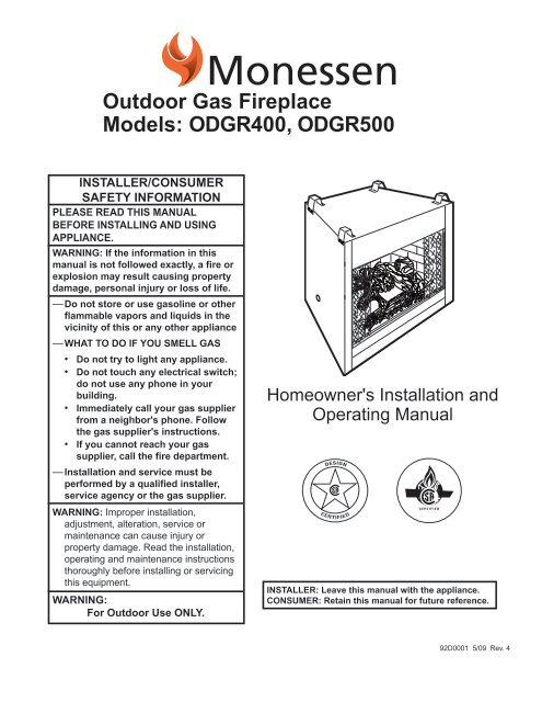
ODGR400, ODGR500 - Unvented Gas Log Heater or Vented ...
ODGR400, ODGR500 - Unvented Gas Log Heater or Vented ...
ODGR400, ODGR500 - Unvented Gas Log Heater or Vented ...

You also want an ePaper? Increase the reach of your titles
YUMPU automatically turns print PDFs into web optimized ePapers that Google loves.
ODGR Series Outdo<strong>or</strong> <strong>Gas</strong> FireplaceMoisture ResistanceThis outdo<strong>or</strong> fireplace will shed moderate amounts ofwater, but is not waterproof. Water and condensing watervap<strong>or</strong> may enter the chase under certain conditions.The fireplace will not perf<strong>or</strong>m as an exteri<strong>or</strong> wall. Moisturepenetration must be considered f<strong>or</strong> constructionthat places the fireplace in structure walls <strong>or</strong> on moisturesensitive surfaces.When installed on exteri<strong>or</strong> walls: MHSC recommendsthe fireplace chase be constructed outside the structure'sweather envelope. Where the platf<strong>or</strong>m meetsthe wall, use a flashing detail similar to that requiredf<strong>or</strong> attached decks. Chase platf<strong>or</strong>ms, including hearthsshould slope away from the structure at 1/4 in per foot.The fireplace can be shimmed level.When installed on surfaces where water may collect <strong>or</strong>cause damage: MHSC recommends a slope of 1/8 into 1/4 in per foot towards the drain p<strong>or</strong>t suggested. Thefireplace can be shimmed level.Hearths should slope away from the front of the fireplaceand chase at 1/8 in to 1/4 in per foot. Metal safetystrips must be on top of any combustible hearth materialsused f<strong>or</strong> moisture management.Screened P<strong>or</strong>ch InstallationThe ODGR may be installed safely and is design certifiedby CSA to be installed in a screened p<strong>or</strong>ch withthese guidelines:Minimum p<strong>or</strong>ch area...............................96 sq. feet (9 sq m)Minimum celing height...................................... 92" (234 cm)Minimum of two (2) walls must be screenedMinimum top of screen height, side walls.........6'6" (198 cm)Minimum screen area.............................64 sq. feet (6 sq m)Clearance to CombustiblesAppliancesTop...........................................................0” (0 mm)Bottom.....................................................0” (0 mm)Side.........................................................0” (0 mm)Back.........................................................0” (0 mm)Perpendicular Sidewall............................0” (0 mm)Top of unit to ceiling...........................36” (914 mm)Front of unit to combustibles.............36” (914 mm)MantelsWARNING: A 4" hood must be used if amantel is to be installed.The height that a combustible mantel is fitted above thefireplace is dependent on the depth of the mantel. Thisalso applies to the distance between the mantel leg (iffitted) and the fireplace.F<strong>or</strong> the c<strong>or</strong>rect mounting height and widths refer toFigures 3a and 3bNoncombustible mantels and legs may be installed atany height and width around the appliance.Side ViewWhen using paint <strong>or</strong> lacquer to finish themantel, such paint <strong>or</strong> lacquer must be heatresistant to prevent discol<strong>or</strong>ation.Maintain minimum3/4" (19 mm)clearance tocombustible.ABYZFireplaceTop of CombustionChamberCFM146Ref. Mantel Ref. Mantel From TopShelf Depthof Comb. ChamberYCFM1468" (203 mm) DV Mantel Chart A 28" (711 mm)Z 1¹⁄₂" (38 mm)7/5/01 staB 26" (660 mm)Fig. 3a Mantel clearances.HearthStandoffA hearth is not mandat<strong>or</strong>y but is recommended f<strong>or</strong>aesthetic purposes. We recommend a noncombustiblehearth.92D0001
ODGR Series Outdo<strong>or</strong> <strong>Gas</strong> FireplaceHearths should slope away from the front of the fireplaceand chase at 1/8 in to 1/4 in per foot. Metal safetystrips must be on top of any combustible hearth materialsused f<strong>or</strong> moisture management.CFM164BlackSurroundFaceMantelLegJIHGFFraming and FinishingCheck appliance to make sure it is levelledand properly positioned.CFM164aSide ofMantel Leg Combustion Chart Chamber06/22/01 staL KMNORef. Mantel Ref. Mantel Leg FromLeg Depthof Comb. OpeningF 14" (356 mm) K 14" (356 mm)CFM170G 12" (305 DV mm) Builder Front L 12" (305 mm)HView10" (254 mm) M 10" (254 mm)I 8" (203 mm) N 8" (203 mm)J 1¹⁄₂" (38 mm) O 1¹⁄₂" (38 mm)Fig. 3b Combustible mantel leg minimum installation.Moisture ResistanceCFM170This outdo<strong>or</strong> fireplace will shed moderate amounts ofwater, but is not waterproof. Water and condensing watervap<strong>or</strong> may enter the chase under certain conditions.The fireplace will not perf<strong>or</strong>m as an exteri<strong>or</strong> wall. Moisturepenetration must be considered f<strong>or</strong> constructionthat places the fireplace in structure walls <strong>or</strong> on moisturesensitive surfaces.When installed on exteri<strong>or</strong> walls: MHSC recommendsthe fireplace chase be constructed outside the structure'sweather envelope. Where the platf<strong>or</strong>m meetsthe wall, use a flashing detail similar to that requiredf<strong>or</strong> attached decks. Chase platf<strong>or</strong>ms, including hearthsshould slope away from the structure at 1/4 in per foot.The fireplace can be shimmed level.When installed on surfaces where water may collect <strong>or</strong>cause damage: MHSC recommends a slope of 1/8 into 1/4 in per foot towards the drain p<strong>or</strong>t suggested. Thefireplace can be shimmed level.The appliance should only be mounted on the followingsurfaces:• A flat combustible (burnable) surface.• A raised wooden platf<strong>or</strong>m.• A concrete block <strong>or</strong> other solid object placedbeneath each of the four c<strong>or</strong>ners of the appliance.To mount the appliance:1. Choose unit location.2. Four (4) nailing flanges are supplied with the fireplace(found on the fireplace hearth). To level thebox and secure it firmly in place, remove the nailingflanges from the hearth and install at the sides of thefireplace as shown in Figure 4.Fig. 4 Adjustable drywall strip (nailing flange).FinishingFP5499/29/97BR/BCNail TopStandoffsNail Side-NailingFlangesFP549CAUTION: All joints between the finishedwall and the appliance surround (top andsides) may be sealed only with non-combustiblematerial. Only noncombustiblematerial can be applied as facing to the appliancesurround (the black painted face).Finish the wall with the material of your choice. Refer toFigures 3a and 3b f<strong>or</strong> specific clearances when installinga combustible mantel <strong>or</strong> other combustible projection.92D0001
ODGR Series Outdo<strong>or</strong> <strong>Gas</strong> Fireplace<strong>Gas</strong> SpecificationMax. Min.Model Fuel <strong>Gas</strong> Control Input Input<strong>ODGR400</strong>NV Nat. Millivolt Hi/Lo 60,000 42,600<strong>ODGR400</strong>PV Prop. Millivolt Hi/Lo 60,000 44,000<strong>ODGR500</strong>NV Nat. Millivolt Hi/Lo 60,000 42,600<strong>ODGR500</strong>PV Prop. Millivolt Hi/Lo 60,000 44,000<strong>Gas</strong> Inlet & Manifold PressuresNatural LPMinimum Inlet Pressure 5.5” w.c. 11.0” w.c.Maximum Inlet Pressure 14.0” w.c. 14.0” w.c.Manifold Pressure 3.5”w.c. 10.0” w.c.<strong>ODGR400</strong> / <strong>ODGR500</strong>Certified toFig. 5 Valve access.FP1414ODUVSRvalve access11/24/03 djtFP1414CSA 4-96<strong>Log</strong>o BrickHigh ElevationsInput ratings are shown in BTU per hour and arecertified without deration from elevations up to4,500 feet (1,370 m) above sea level.Nuisance outages may occur at altitudes above4,500 feet (1,370 m) if dirt, dust, lint and/<strong>or</strong> cobwebsare allowed to accumulate on burner and/<strong>or</strong>ODS pilot. Monthly inspection and cleaning is recommendedf<strong>or</strong> altitudes above 4,500 feet (1,370 m)F<strong>or</strong> elevations above 4,500 feet (1,370 m), installationsmust be in acc<strong>or</strong>dance with the currentANSI Z223.1/NFPA 54 and/<strong>or</strong> local codes havingjurisdiction.FP1415Fig. 6 Lift brick with logo on it to access valve.NOTE: When installation ison a hard, flat surface (suchas concrete), the surfacemust be sloped 1/4" per footaway from any structure.FP1415lift brick access11/24/03 djtBlocking1/2” (13 mm)Valve AccessValve access can be accomplished in one of two ways:1. Remove the front panel just below the front of thehearth pan. This is accomplished by lifting on thepanel. To replace the valve access panel line up thetwo pins with the holes in the surround bottom andpush the panel over the front of the hearth pan. (Fig.5)2. Lift the brick with the logo on it. (Fig. 6)FP1642aconcrete install9/06Hard, Flat Surface(i.e. concrete)Fig. 7 Exteri<strong>or</strong> chase installation.FP1642a92D0001
ODGR Series Outdo<strong>or</strong> <strong>Gas</strong> FireplaceNailingFlangeFP1416Fig. 8 Parts identification.Nailing FlangeFig. 9 Exteri<strong>or</strong> chase installation.*Do not installheader until unitis in place.StandoffSurroundValve Access Panel<strong>Gas</strong>Line AccessScreenGrateFireboxFP1416ODUVSRInteri<strong>or</strong> sides of an exteri<strong>or</strong> chasepart idshould be weather proof11/24/03 djt*Do not installheader until unitis in place.FP1416ODUVSRpart id11/24/03 djtScreenGrateFireboxStandoffValve Access PanelSurround<strong>Gas</strong>LineAccessFP1644<strong>Gas</strong> Line InstallationThis appliance must be isolated from the gas supplypiping system by closing its individual manual shut offvalve during any pressure equal to <strong>or</strong> less than 1/2 psig(3.45 kPa).The appliance and its individual shutoff valve must bedisconnected from the gas supply piping system duringany pressure testing of that system at test pressures inexcess of 1/2 psig (3.45 kPa).If gas piping from the source to the appliance locationhas not been accomplished, install the required pipe.Consult local plumbing code to assure proper pipe size.The gas pipeline can be brought in through the rightside of the appliance. A knockout is provided to allowf<strong>or</strong> the gas pipe installation and testing of any gas connection.NOTE: The gas line connection can be made with 3/8"copper tubing approved f<strong>or</strong> propane <strong>or</strong> natural gas, 1/2"rigid pipe <strong>or</strong> an approved flex connect<strong>or</strong>, then reducedto 3/8" to the appliance. Because some municipalitieshave some additional local codes, it is always best toconsult your local auth<strong>or</strong>ity.U.S.: Consult the current National Fuel <strong>Gas</strong> Code, ANSIZ223.1/NFPA 54.Canada: CSA - B149.1 installation code.Test f<strong>or</strong> leaks. Use a 50/50 solution of liquid soap andwater to test f<strong>or</strong> leaks at gas fittings and joints. Applywater/soap solution with brush only - do not over apply.NEVER test with an open flame.The gas control is equipped with a captured screw typepressure test point, theref<strong>or</strong>e it is not necessary to providea 1/8" test point up stream of the control.When using copper <strong>or</strong> flex connect<strong>or</strong> use only approvedfittings. Always provide a union so that gas line canbe easily disconnected f<strong>or</strong> burner <strong>or</strong> fan servicing.See gas specification f<strong>or</strong> pressure details and ratings.NOTE: If flex connect<strong>or</strong> is used, it must be kept insideof the appliance. (Fig. 10)1/2" <strong>Gas</strong> Supply1/2" x 3/8" Shut-off Valve3/8" Nipple3/8" Union3/8" NippleFP598Fig. 10 Typical gas supply installation.GF598nvb GAS SUPPLY INSTALL12/4/9792D0001
ODGR Series Outdo<strong>or</strong> <strong>Gas</strong> FireplaceRemote Wall SwitchNOTE: Use an approved outdo<strong>or</strong> switch.1. Thread wire through the low voltage wire access holelocated on either side of unit. Do not cut wire <strong>or</strong> insulationon metal edges. Ensure that wire is protected.Run the other end to a conveniently located wallreceptacle box.2. Attach wire to switch and install switch into receptaclebox. Attach cover plate to switch.3. Connect wiring to gas valve. Refer to Figure 11.CAUTION: Do not wire millivolt remotewall switch f<strong>or</strong> gas appliance to a 120vpower supply.F<strong>or</strong> lighting instructions, refer to Page 12.NOTE: If glass do<strong>or</strong>s are installed, the unit must beoperated with the do<strong>or</strong>s fully open. (Fig. 12) If thedo<strong>or</strong>s are not fully open, the thermodisk will automaticallyturn the unit off.CAUTION: After the unit cools, the burnerwill automatically come on.On/OffSwitchPilotFig. 11 Remote switch wiring.ThermodiskTPTH TP THValveHV105OPENC<strong>or</strong>rect Wrong MD706-7Fig. 12 C<strong>or</strong>rect do<strong>or</strong> position during operation.HV105Generic <strong>Gas</strong> Valve9/22/99 djtMD706-7Glass Do<strong>or</strong> Position1/20/9992D0001
ODGR Series Outdo<strong>or</strong> <strong>Gas</strong> FireplaceOperating Instructions<strong>Log</strong> Installation1. Remove logs from the packaging.As with all plastic, these bagsare not toys and should alwaysbe kept away from children andinfants.2. Place left rear log on rear log supp<strong>or</strong>t.Ensure that log is firmly positioned andthere is no side-to-side movement. (Figs.13 & 14)3. Carefully place Ember <strong>Log</strong> betweengrate and burner. (Figs. 13 & 14)4. Place the front of right rear log on theburner and the back of the log on therear log supp<strong>or</strong>t.5. Place the top logs onto the locat<strong>or</strong>notches. Ensure the logs are secure.(Fig. 13 & 14)Left Cross<strong>Log</strong>Left Rear<strong>Log</strong>Right Cross<strong>Log</strong>Right Rear<strong>Log</strong>Ember<strong>Log</strong>LG317Fig. 13 <strong>ODGR400</strong> log placement.Left Rear<strong>Log</strong>Left Cross<strong>Log</strong>Middle Cross <strong>Log</strong>Right Cross<strong>Log</strong>Right Rear<strong>Log</strong><strong>Log</strong> RightEmberFirst FiringUpon completing the gas line connection, a smallamount of air will be trapped in the line. Whenfirst lighting the unit with pilot light, it will take afew minutes to purge the trapped air. Once purgingis complete, the pilot and burner will light andoperate as indicated in the instruction manual.Subsequent lightings of the appliance will notrequire purging.LG317WhenUVODSR36lit f<strong>or</strong> the first time, the appliance will emita slight od<strong>or</strong> f<strong>or</strong> an hour <strong>or</strong> two. This is due tologspaint and lubricants used in the manufacturingprocess. 11/24/03 After each djt lighting, vap<strong>or</strong> may condenseand fog the glass; this moisture disappearsin a few minutes of burning.<strong>Log</strong> LeftEmberLG318GrateFig. 14 <strong>ODGR500</strong> log placement.1092D0001
Flame AdjustmentF<strong>or</strong> units equipped with Hi/Lo valves, flame adjustmentis accomplished by rotating the Hi/Lo adjustment knoblocated near the center of the gas control.Turncounterclockwiseto increaseflame heightFig. 15 Flame adjustment knob f<strong>or</strong> SIT820 valve.LOFlame CharacteristicsHITurn clockwiseto lowerflame heightFP390It is imp<strong>or</strong>tant to periodically FLAME ADJUSTMENT perf<strong>or</strong>m a visual KNOBcheck ofthe pilot and the burner 11/21/96 flames. Compare them to the illustrationsbelow (Figs. 16, 17, 18). If any of the flamesappear abn<strong>or</strong>mal call a service person.ODGR Series Outdo<strong>or</strong> <strong>Gas</strong> FireplaceFig. 16 Proper pilot flame height.3/8"-1/2"NOVA SIT PilotFP581NVB-PILOTS12/4/97ELECTRONIGNITIONFP581Red GlowFig. 17 <strong>ODGR400</strong> flame appearance.LG319Fig. 18 <strong>ODGR500</strong> flame appearance.LG319ODUVSR36log flames11/24/03 djtLG32092D000111
ODGR Series Outdo<strong>or</strong> <strong>Gas</strong> FireplaceOptional Weather EnclosureAn optional weather enclosure is available to protectthe burner when not in use.CAUTION: Do not use the weather enclosureif the unit has glass do<strong>or</strong>s installed.Installation Instructions1. Turn the unit OFF and allow to cool.2. Grab the weather enclosure by the handle(s).3. Slide the top of the weather enclosure up betweenthe back of the surround top and the screen rail.(Fig. 19)4. Push the bottom of the weather enclosure into thefirebox just enough to clear the valve access coverand set down. (Fig. 20)Screen RailSurround TopWeather EnclosureOptional Stainless Steel HoodAn optional stainless steel hood is available f<strong>or</strong> both the<strong>ODGR400</strong> and <strong>ODGR500</strong>.NOTE: The stainless steel hood may NOTbe used when the optional glass do<strong>or</strong>s areinstalled.Installation Instructions:1. Turn the unit off and allow to cool.2. Place the hood so the 2B\," (67 mm) slot clears thesens<strong>or</strong> plate located under the fireplace opening onthe top left side. (Fig. 21)3. Secure the hood to the unit using the three (3) slotsin the hood and the pilot holes in the unit with thestainless steel sheet metal screws provided. (Fig.21)4. Align the sides of the hood so the pilot holes on theright and left sides of the unit are exposed throughthe slots on the ends of the hood. Secure using theremaining stainless steel sheet metal screws. (Fig.21)StainlessSteel HoodKT457place we top4/1/04 djtKT457Fig. 19 Place top of weather enclosure between surround topand screen rail.StainlessSteel SheetMetal Screws(5)Sens<strong>or</strong> Plate SlotScreenHearth BrickValve Access CoverKT458Fig. 20 Push bottom of weather enclosure into firebox. FP1635Fig. 21 Secure stainless steel hood with five (5) sheet metalscrews.KT458place we bottom4/1/04 djt1292D0001
Lighting and Operating InstructionsFOR YOUR SAFETY READ BEFORE LIGHTINGA. This heater has a pilot which must be lit manually.When lighting the pilot follow theseinstructions exactly.B. BEFORE LIGHTING smell all around theheater area f<strong>or</strong> gas. Be sure to smell next tothe flo<strong>or</strong> because some gas is heavier than airand will settle on the flo<strong>or</strong>.WHAT TO DO IF YOU SMELL GAS• Do not try to light any fireplace• Do not touch any electric switch• Do not use any phone in your building• Immediately call your gas supplier from aneighb<strong>or</strong>'s phone. Follow the gas supplier'sinstructions.1. STOP! Read the safety inf<strong>or</strong>mation above.2. Turn off all electrical power to the fireplace.3. F<strong>or</strong> MN/MP/TN/TP appliances ONLY, go on toStep 4. F<strong>or</strong> RN/RP appliances turn the On/Offswitch to “OFF” position <strong>or</strong> set thermostat tolowest level.4. Open control access panel.5. Push in gas control knob slightly and turnclockwise to "OFF".Lighting InstructionsODGR Series Outdo<strong>or</strong> <strong>Gas</strong> FireplaceWARNING:If you do not follow these instructions exactly, a fire <strong>or</strong> explosionmay result causing property damage, personal injury <strong>or</strong> loss of life.1PILOTPILOTOFF• If you cannot reach your gas supplier, call theFire DepartmentC. Use only your hand to push in <strong>or</strong> turn the gascontrol knob. Never use tools. If the knob will notpush in <strong>or</strong> turn by hand, do not try to repair it, calla qualified service technician. Applying f<strong>or</strong>ce <strong>or</strong>any attempted repair may result in a fire <strong>or</strong> explosion.D. Do not use this fireplace if any part has beenunder water. Immediately call a qualified servicetechnician to inspect the heater and to replaceany part of the control system and any gas controlwhich has been under water.10. Push the control knob all the way in and hold.Immediately light the pilot by repeatedly depressingthe piezo spark ignit<strong>or</strong> until a flame appears.Continue to hold the control knob in f<strong>or</strong> about one(1) minute after the pilot is lit. Release knob and itwill pop back up. Pilot should remain lit. If it goesout, repeat steps 5 through 8.• If knob does not pop up when released, stop3/8" - 1/2"OFF Pilot5432OFFOFFONONEuro SIT SIT NOVA Honeywell6. Wait five (5) minutes to clear out any gas.Then smell f<strong>or</strong> gas, including near the flo<strong>or</strong>. Ifyou smell gas, STOP! Follow "B" in the safetyFP1067inf<strong>or</strong>mation above.lightingIfinstructionyou do not smell gas, goto the next step. knobs7. Remove glass do<strong>or</strong>3/9/01bef<strong>or</strong>edjtlighting pilot. (SeeGlass Frame Removal section).8. Visibly locate pilot by the main burner.9. Turn knob on gas control counterclockwiseto "PILOT".and immediately call your service technician <strong>or</strong>gas supplier.• If after several tries, the pilot will not stay lit,FP1068turn the gas control knobLightingto "OFF"instructionsand call yourservice technician <strong>or</strong> gas Pilots supplier.11. Replace glass do<strong>or</strong>.12. Turn gas control knob to “ON” position.13. F<strong>or</strong> RN/RP appliances turn the On/Off switch to“ON” position <strong>or</strong> set thermostat to desired setting.14. Turn on all electrical power to the fireplace.1. Turn the On/Off switch to "Off" position <strong>or</strong> setthe thermostat to lowest setting.2. Turn off all electric power to the fireplace ifservice is to be perf<strong>or</strong>med.To Turn Off <strong>Gas</strong> to <strong>Heater</strong>3. Open control access panel.4. Push in gas control knob slightly and turnclockwise to "OFF". Do not f<strong>or</strong>ce.5. Close control access panel.92D000113
ODGR Series Outdo<strong>or</strong> <strong>Gas</strong> FireplaceNova SIT 820 Standing PilotTroubleshootingSTART<strong>Gas</strong> Supply OnNOCHECKSupply Line Hooked upShutoff Valve OpenYESPilot Lights withPiezo Ignit<strong>or</strong>YESPilot Stays LitYESNONOLockout has engaged. Wait 60seconds and try again.Piezo not tight enough f<strong>or</strong> goodground.F<strong>or</strong> spark at electrode whiledepressing Piezo (Red Button)1/8" gap to pilot hood needed.All wiring connectionsReplace Piezo Ignit<strong>or</strong>ThermodiskF<strong>or</strong> Air in the linesThermopile needs a minimum325mV. Adjust pilot flame height.All wiring connectionsReplace ThermopileThermocouple needs a minimumof 14mV.Defective valve. Turn to pilot,meter should read greater than100mV.ThermodiskPilot Lights MainBurnerYESNOWall switch is not turned on.Watch f<strong>or</strong> grounded wires!Thermopile needs a minimum325mVPlugged burner <strong>or</strong>ificeDo<strong>or</strong>s not fully open (Fig. 10)System OKFP396NVC-standing pilot troubleshooting5/6/98FP3961492D0001
ODGR Series Outdo<strong>or</strong> <strong>Gas</strong> FireplaceMaintenanceBurner and Burner CompartmentIt is imp<strong>or</strong>tant to keep the burner and the burnercompartment clean. At least once per year the logsshould be removed and the burner compartmentvacuumed and wiped out. Remove and replace the logsas per the instructions in this manual.Always handle the logs with care as they are fragileand may also be hot if the fireplace has been inuse.CleaningThere are three methods of cleaning the polished stainlesssteel of your outdo<strong>or</strong> fireplace;1. Warm, soapy water - to loosen any dirt film2. Glass cleaner with ammonia3. Stainless steel cleaner available at hardware st<strong>or</strong>esRegardless of which method is used, remember thatanything with too much abrasive may dull the finish.Cleaning the Standing PilotControl SystemThe burner and control system consists of:• main burner• gas <strong>or</strong>ifice• pilot burner• thermopile• combination millivolt gas valveMost of these components may require only an occasionalcheckup and cleaning and some may require adjustment.If repair is necessary, it should be perf<strong>or</strong>medby a qualified technician.In <strong>or</strong>der to properly clean the burner and pilot assembly,turn off the gas to the unit, remove logs exposing theburner and pilot assembly. Clean all f<strong>or</strong>eign materialsfrom the top of the burner. Check to make sure thatburner parts are clean. Visually inspect pilot. Brush <strong>or</strong>blow away any dust <strong>or</strong> lint accumulation If pilot <strong>or</strong>ifice isplugged, disassembly may be required to remove anyf<strong>or</strong>eign material from the <strong>or</strong>ifice <strong>or</strong> tubing.To obtain proper operation, it is imperative that the pilotand burner's flame characteristics are steady, not lifting<strong>or</strong> floating.Typically, the top 3/8" <strong>or</strong> 1/2" of the thermopile shouldbe engulfed in the pilot flame. (Fig. 16)To adjust pilot burner, turn pilot screw marked "pilot" f<strong>or</strong>proper flame size.The air shutter is set at fact<strong>or</strong>y no adjustment should benecessary.92D000115
ONODGR Series Outdo<strong>or</strong> <strong>Gas</strong> Fireplacead1. <strong>ODGR400</strong> <strong>Log</strong>s 1. <strong>ODGR500</strong> <strong>Log</strong>sbbadecc234a/bhfg256789 101112a/b17THTP TP THPILOTLOHIOFFE AOFF19a/b2120221314151618a/bMHSC reserves the right to make changes in design, materials, specifications, prices and discontinue col<strong>or</strong>s and products at any time, withoutnotice.<strong>ODGR400</strong>, <strong>ODGR500</strong>Ref. Description <strong>ODGR400</strong> <strong>ODGR500</strong>1. <strong>Log</strong>s - Complete Set 20007180 200072001a. <strong>Log</strong> - Left Rear 20007175 200071931b. <strong>Log</strong> - Right Rear 20007176 200071941c. <strong>Log</strong> - Right Cross 7114 20007178 200071971d. <strong>Log</strong> - Left Cross oduvsr36/42A20007177 200071951e. <strong>Log</strong> - Middle Cross parts-- 200071961f. <strong>Log</strong> - Left Ember11/24/03 DJT-- 200071981g. <strong>Log</strong> - Right Ember -- 200071991h. Front Ember <strong>Log</strong> 20007179 --2. Burner Housing Assembly 20007119 200071873. Ceramic Tile (single) 57803 578034a. Burner Orifice - Natural (Manifold & Orifice) 20007106 200071064b. Burner Orifice - LP (Manifold & Orifice) 20007159 200071596. Side Brick - Left* 20002008 <strong>or</strong> 92D0004 20002021 <strong>or</strong> 92D00117. Back Brick* 20002006 <strong>or</strong> 92D0002 20002019 <strong>or</strong> 92D00058. Side Brick - Right* 20002007 <strong>or</strong> 92D0003 20002020 <strong>or</strong> 92D00069. Left Hearth Brick* 20007158 <strong>or</strong> 92D0008 20007241 <strong>or</strong> 92D001010. Right Hearth Brick* 20007157 <strong>or</strong> 92D0007 20007240 <strong>or</strong> 92D000911. Piezo 52464 5246412a. Pilot Top Convertible - Natural (3 Way Assembly) 10002264 1000226412b. Pilot Top Convertible - LP (3 Way assembly) 10002265 1000226513. Thermopile 18" 7533113 753311371141692D0001
ODGR Series Outdo<strong>or</strong> <strong>Gas</strong> Fireplace<strong>ODGR400</strong>, <strong>ODGR500</strong> (continued)Ref. Description <strong>ODGR400</strong> <strong>ODGR500</strong>14. Pilot Tubing 10001296 1000129615. Cable Ignit<strong>or</strong> 24" 7522432 752243216. Thermocouple 24" 7531137 753113717. Grate 20006819 2000681918a. Pilot Orifice - Natural 10002268 1000226818b. Pilot Orifice - LP 10002269 1000226919a. Valve NOVA - Natural 7529141 752914119b. Valve NOVA - LP 7529142 752914220a. Air Shutter - Natural 20009120 2000012921. Hearth Brick Cover 20007183 <strong>or</strong> 92D0016 20007183 OR 92D001622. Thermodisk 20007568 2000756823. Conversion Kit LP to Natural 20008549 2000855024. Conversion Kit Natural to LP 20008548 2000855125. Valve Access Panel Assy 20009119 20008296* When <strong>or</strong>dering replacement firebrick, check the serial number and plant code of the fireplace, located on the ULlabel inside the firebox. Serial numbers/plant code with a 'P' require the firebrick listed first under the respectivefireplace (white brick). Serial numbers/plant code with an 'X' require the firebrick listed second under the respectivefireplace (grey brick).Contact MHSC f<strong>or</strong> questions concerning prices and policiescovering replacement parts. Parts may be <strong>or</strong>dered throughyour Monessen Fireplaces distribut<strong>or</strong> <strong>or</strong> dealer.You will need the following inf<strong>or</strong>mation when <strong>or</strong>dering replacementparts:1. The appliance model number.2. The serial number.3. A description of the part.Should you need additional inf<strong>or</strong>mation beyond what yourdealer can furnish, contact:MHSC149 Cleveland DriveParis, KY 40361Model and serial numbers are listed on the ratingplate (located on right side of combustionchamber).Rec<strong>or</strong>d your model and serial numbers here f<strong>or</strong>future reference:Model #Serial #________________________________________________________92D000117
ODGR Series Outdo<strong>or</strong> <strong>Gas</strong> FireplaceAccess<strong>or</strong>iesThe following access<strong>or</strong>ies are available from your local Majestic Fireplaces distribut<strong>or</strong>. Each access<strong>or</strong>y comes witha separate installation instruction f<strong>or</strong> mounting to the particular firebox. Be sure to read each instruction th<strong>or</strong>oughlybef<strong>or</strong>e installing.Access<strong>or</strong>y Description Model Number4" Stainless Steel F<strong>or</strong> heater up to 40,000 BTU's and mantels UV36SH4Hood 8" high by 12" wide UV42SH4Glass Do<strong>or</strong>s Designed to enhance the look of the fireplace 36GDKSSSR42GDKSSSRWeather Enclosure Designed to protect the burner when unit is not in use ODG36WEODG42WEDrain Pan Designed to be installed under unit to shed water 20014194 (36" models)by means of containing and piping way from structure 20014195 (42" models)CAUTION: This firebox is a highly engineered system, and, as such, must be operated only with MHSC approvedcomponents. If you use an unapproved component to make any modifications, you may create a possiblefire hazard and will void the MHSC warranty. In addition, such action may void the coverage provided bythe owner's insurance.1892D0001
What is Covered and F<strong>or</strong> How LongLIMITED WARRANTYFact<strong>or</strong>y-Build Fireplace and Components(Except Blowers)ODGR Series Outdo<strong>or</strong> <strong>Gas</strong> FireplaceFive-Year Coverage: F<strong>or</strong> five years from the date this fireplace and components are first purchased f<strong>or</strong> use, MHSCwill, at its option, repair <strong>or</strong> replace any defective part of this fireplace <strong>or</strong> components, <strong>or</strong> refund to you a sum not toexceed the fact<strong>or</strong>y retail price in effect at the time of purchase.Ten-Year Coverage: From the sixth through the tenth year following the date this fireplace <strong>or</strong> access<strong>or</strong>y is firstpurchased f<strong>or</strong> use, MHSC will make available to you, at our fact<strong>or</strong>y, a free replacement f<strong>or</strong> any defective part in thisfireplace <strong>or</strong> access<strong>or</strong>y.Twenty-Five-Year Availability of Replacement Parts: From the eleventh through the twenty-fifth year following thedate this fireplace <strong>or</strong> access<strong>or</strong>y is first purchased f<strong>or</strong> use, MHSC will make available at our fact<strong>or</strong>y replacement partsf<strong>or</strong> this fireplace <strong>or</strong> access<strong>or</strong>y, which you may purchase f<strong>or</strong> the list price current at the time your purchase <strong>or</strong>der isreceived.What is Not Covered• This limited warranty does not cover:• Transp<strong>or</strong>tation <strong>or</strong> shipping cost.• The cost of a service call to diagnose trouble.• Painted surfaces.• Damage <strong>or</strong> defect caused by improper installation, accident, misuse, abuse <strong>or</strong> alteration.• Po<strong>or</strong> ventilation of smoke <strong>or</strong> gases caused by air-conditioning and heating systems, exhaust fans, <strong>or</strong> pressure differentialsproduced by wind.• Broken glass components.• Cracks in ceramic and castable parts that do not affect safe operation.• We do not warrant this fireplace to be in compliance with your local building code. Building codes vary greatlythroughout the country, and you should determine whether your local building code contains restrictions on the useof this fireplace bef<strong>or</strong>e you purchase it.• Blowers <strong>or</strong> fans, which are warranted separately.• Heat loss due to the passage of heat <strong>or</strong> air through <strong>or</strong> around the fireplace.Also, under our five year coverage, we do not pay the cost of removal and replacement of any p<strong>or</strong>tion of the structurein which the fireplace is situated, made necessary by the repair, removal <strong>or</strong> re-installation of the fireplace.And under our twenty-five year warranty of availability of replacement parts, we only promise to maintain a supply ofreplacement parts at our fact<strong>or</strong>y f<strong>or</strong> you to purchase.Limitations and Exclusions1. No one has auth<strong>or</strong>ity to add to <strong>or</strong> vary this limited warranty, <strong>or</strong> to create f<strong>or</strong> MHSC any other obligations of liabilityin connection with this fireplace and access<strong>or</strong>y.2. MHSC shall not be liable f<strong>or</strong> incidental, consequential, special <strong>or</strong> contingent damages you might suffer as a resultof its breach of this written warranty <strong>or</strong> any implied warranty. Some states do not allow the exclusion of limitation ofincidental <strong>or</strong> consequential damages, so the above limitations may not apply to you.3. This warranty applies only to a fireplace sold and used in the United States.F<strong>or</strong> inf<strong>or</strong>mation about this warranty, contact:MHSC149 Cleveland DriveParis, Kentucky 4036192D000119
MHSC149 Cleveland Drive • Paris, Kentucky 40361www.mhsc.com