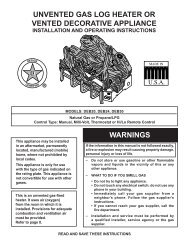
Manual - Unvented Gas Log Heater or Vented Decorative Appliance
Manual - Unvented Gas Log Heater or Vented Decorative Appliance
Manual - Unvented Gas Log Heater or Vented Decorative Appliance
- No tags were found...

You also want an ePaper? Increase the reach of your titles
YUMPU automatically turns print PDFs into web optimized ePapers that Google loves.
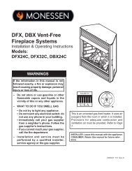
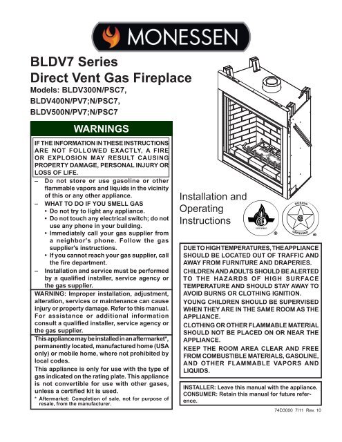
BLDV7 Series<br />
Direct Vent <strong>Gas</strong> Fireplace<br />
Models: BLDV300N/PSC7,<br />
BLDV400n/pv7;n/pSC7,<br />
BLDV500n/pv7;n/psc7<br />
WARNINGS<br />
If the inf<strong>or</strong>mation in these instructions<br />
are not followed exactly, a fire<br />
<strong>or</strong> explosion may result causing<br />
property damage, personal injury <strong>or</strong><br />
loss of life.<br />
– Do not st<strong>or</strong>e <strong>or</strong> use gasoline <strong>or</strong> other<br />
flammable vap<strong>or</strong>s and liquids in the vicinity<br />
of this <strong>or</strong> any other appliance.<br />
– WHAT TO DO IF YOU SMELL GAS<br />
• Do not try to light any appliance.<br />
• Do not touch any electrical switch; do not<br />
use any phone in your building.<br />
• Immediately call your gas supplier from<br />
a neighb<strong>or</strong>'s phone. Follow the gas<br />
supplier's instructions.<br />
• If you cannot reach your gas supplier, call<br />
the fire department.<br />
– Installation and service must be perf<strong>or</strong>med<br />
by a qualified installer, service agency <strong>or</strong><br />
the gas supplier.<br />
WARNING: Improper installation, adjustment,<br />
alteration, services <strong>or</strong> maintenance can cause<br />
injury <strong>or</strong> property damage. Refer to this manual.<br />
F<strong>or</strong> assistance <strong>or</strong> additional inf<strong>or</strong>mation<br />
consult a qualified installer, service agency <strong>or</strong><br />
the gas supplier.<br />
This appliance may be installed in an aftermarket*,<br />
permanently located, manufactured home (USA<br />
only) <strong>or</strong> mobile home, where not prohibited by<br />
local codes.<br />
This appliance is only f<strong>or</strong> use with the type of<br />
gas indicated on the rating plate. This appliance<br />
is not convertible f<strong>or</strong> use with other gases,<br />
unless a certified kit is used.<br />
* Aftermarket: Completion of sale, not f<strong>or</strong> purpose of<br />
resale, from the manufacturer.<br />
Installation and<br />
Operating<br />
Instructions<br />
743000<br />
BLDV 7 cover<br />
DUE TO HIGH TEMPERATURES, THE APPLIANCE<br />
SHOULD BE LOCATED OUT OF TRAFFIC AND<br />
AWAY FROM FURNITURE AND DRAPERIES.<br />
CHILDREN AND ADULTS SHOULD BE ALERTED<br />
TO THE HAZARDS OF HIGH SURFACE<br />
TEMPERATURE AND SHOULD STAY AWAY TO<br />
AVOID BURNS OR CLOTHING IGNITION.<br />
YOUNG CHILDREN SHOULD BE SUPERVISED<br />
WHEN THEY ARE IN THE SAME ROOM AS THE<br />
APPLIANCE.<br />
CLOTHING OR OTHER FLAMMABLE MATERIAL<br />
SHOULD NOT BE PLACED ON OR NEAR THE<br />
APPLIANCE.<br />
Keep the room area clear and free<br />
from combustible materials, gasoline,<br />
and other flammable vap<strong>or</strong>s and<br />
liquids.<br />
INSTALLER: Leave this manual with the appliance.<br />
CONSUMER: Retain this manual f<strong>or</strong> future reference.<br />
74D3000 7/11 Rev. 10
CONTENTS<br />
BLDV7 Series <strong>Gas</strong> Fireplace<br />
Thank you and congratulations on your purchase of a<br />
Monessen Fireplace.<br />
PLEASE READ THE INSTALLATION AND OPERATION INSTRUCTIONS BEFORE USING THE APPLIANCE!<br />
IMPORTANT: Read all instructions and warnings carefully bef<strong>or</strong>e starting installation.<br />
Failure to follow these instructions may result in a possible fire hazard and will void the warranty.<br />
Imp<strong>or</strong>tant Safety Inf<strong>or</strong>mation...................................... 3<br />
Code Approval.............................................................. 4<br />
Product Specifications................................................ 5<br />
High Elevations........................................................ 5<br />
<strong>Gas</strong> Pressures......................................................... 5<br />
<strong>Gas</strong> Specifications & Orifice Size............................ 5<br />
Pre-Installation Inf<strong>or</strong>mation<br />
Fireplace Dimensions & Framing............................ 6<br />
Bef<strong>or</strong>e You Start...................................................... 7<br />
Cold Climate Insulation............................................ 7<br />
Fireplace Location................................................... 8<br />
Clearances.................................................................... 9<br />
Securing Fireplace to Flo<strong>or</strong> <strong>or</strong> Framing................... 10<br />
Vent Installation......................................................... 11<br />
Installation Precautions......................................... 11<br />
General Venting..................................................... 11<br />
Termination Location............................................. 12<br />
Assembling Vent Pipes.......................................... 13<br />
How to Use the Vent Graph................................... 14<br />
Vent Pipe Clearances to Combustibles................. 15<br />
Vertical Sidewall Applications &<br />
Installation............................................................. 16<br />
Below Grade Installation........................................ 18<br />
Vertical Through-the-Roof Applications<br />
& Installation.......................................................... 19<br />
Fireplace Installation................................................. 22<br />
Check <strong>Gas</strong> Type.................................................... 22<br />
Install <strong>Gas</strong> Piping to Fireplace/Burner System<br />
Location................................................................. 22<br />
Check <strong>Gas</strong> Pressure (Millivolt) ................................ 24<br />
Electrical Installation................................................. 24<br />
Electrical Wiring..................................................... 24<br />
Glass Removal........................................................... 25<br />
Remote Wall Switch Installation............................... 26<br />
Optional Fan/Blower Systems (Milli-Volt)................ 26<br />
BLOTBLDV............................................................ 26<br />
Operating Instructions (Milli-Volt)............................ 29<br />
Lighting Pilot f<strong>or</strong> the First Time.............................. 29<br />
Lighting Pilot.......................................................... 30<br />
Lighting Burner...................................................... 31<br />
Checking <strong>Gas</strong> Pressure -<br />
(Signature Command System) .......................... 32<br />
Electrical Wiring (SCS) ............................................. 32<br />
Junction Box Wiring............................................... 33<br />
Command Center Wall Installation........................ 33<br />
Wall Switch Installation.......................................... 33<br />
Signature Command Wiring Diagram.................... 34<br />
Optional Fan/Blower System (SCS).......................... 35<br />
BLOTSDVSC......................................................... 35<br />
BLOTSDV.............................................................. 36<br />
Operating Instructions (SCS).................................... 37<br />
Operating Instructions........................................... 38<br />
To Turn Off <strong>Gas</strong> To <strong>Appliance</strong>................................ 38<br />
Signature Command System Operation.................. 39<br />
Final Installation......................................................... 42<br />
Hearth Brick Placement......................................... 42<br />
Rockwool Placement............................................. 42<br />
<strong>Log</strong> Placement....................................................... 42<br />
Cleaning and Maintenance........................................ 44<br />
Burner, Pilot and Control Compartment................. 44<br />
Pilot Flame............................................................. 44<br />
Burner Flame......................................................... 44<br />
Vent System.......................................................... 45<br />
Glass Do<strong>or</strong>............................................................. 45<br />
<strong>Log</strong>s....................................................................... 45<br />
Rock Wool ............................................................ 45<br />
Troubleshooting<br />
Standing Pilot Ignition............................................ 46<br />
Signature Command System................................. 48<br />
Replacement Parts..................................................... 49<br />
Firebox Components............................................. 49<br />
Standing Pilot Millivolt Control .............................. 50<br />
Signature Command System................................. 52<br />
<strong>Log</strong>s....................................................................... 54<br />
Venting Components............................................. 55<br />
Massachusetts Residents Only................................ 55<br />
Warranty...................................................................... 59<br />
Efficiencies................................................................. 60<br />
<br />
74D3000
BLDV7 Series <strong>Gas</strong> Fireplace<br />
INSTALLER<br />
Please leave these instructions with the appliance.<br />
OWNER<br />
IMPORTANT SAFETY INFORMATION<br />
Please retain these instructions f<strong>or</strong> future reference.<br />
WARNING<br />
• Read this owner’s manual carefully and completely bef<strong>or</strong>e trying to assemble, operate,<br />
<strong>or</strong> service this fireplace.<br />
• Any change to this fireplace <strong>or</strong> its controls can be dangerous.<br />
• Improper installation <strong>or</strong> use of this fireplace can cause serious injury <strong>or</strong> death from<br />
fire, burns, explosions, electrical shock and carbon monoxide poisoning.<br />
This fireplace is a vented product. This fireplace must be<br />
properly installed by a qualified service person. The glass<br />
do<strong>or</strong> must be properly seated and sealed. If this unit is not<br />
properly installed by a qualified service person with glass<br />
do<strong>or</strong> properly seated and sealed, combustion leakage can<br />
occur.<br />
CARBON MONOXIDE POISONING: Early signs of carbon<br />
monoxide poisoning are similar to the flu with headaches,<br />
dizziness and/<strong>or</strong> nausea. If you have these signs, the fireplace<br />
may not have been installed properly. Get fresh air<br />
at once! Have the fireplace inspected and serviced by a<br />
qualified service person. Some people are m<strong>or</strong>e affected<br />
by carbon monoxide than others. These include pregnant<br />
women, people with heart <strong>or</strong> lung disease <strong>or</strong> anemia,<br />
those under the influence of alcohol, and those at high<br />
altitudes.<br />
Propane/LP gas and natural gas are both od<strong>or</strong>less. An<br />
od<strong>or</strong>-making agent is added to each of these gases. The<br />
od<strong>or</strong> helps you detect a gas leak. However, the od<strong>or</strong> added<br />
to these gases can fade. <strong>Gas</strong> may be present even though<br />
no od<strong>or</strong> exists.<br />
Make certain you read and understand all warnings. Keep<br />
this manual f<strong>or</strong> reference. It is your guide to safe and proper<br />
operation of this fireplace.<br />
1. This appliance is only f<strong>or</strong> use with the type of gas<br />
indicated on the rating plate. This appliance is not<br />
convertible f<strong>or</strong> use with other gases unless a certified<br />
kit is used.<br />
2. F<strong>or</strong> propane/LP fireplace, do not place propane/LP<br />
supply tank(s) inside any structure. Locate propane/LP<br />
supply tank(s) outdo<strong>or</strong>s. To prevent perf<strong>or</strong>mance problems,<br />
do not use propane/LP fuel tank of less than 100<br />
lbs. capacity.<br />
3. If you smell gas<br />
• shut off gas supply.<br />
• do not try to light any appliance.<br />
• do not touch any electrical switch; do not use any<br />
phone in your building .<br />
• immediately call your gas supplier from a neighb<strong>or</strong>’s<br />
phone. Follow the gas supplier’s instructions.<br />
74D3000<br />
4. Never install the fireplace<br />
• in a recreational vehicle<br />
• where curtains, furniture, clothing, <strong>or</strong> other flammable<br />
objects are less than 42" from the front, top,<br />
<strong>or</strong> sides of the fireplace<br />
• in high traffic areas<br />
• in windy <strong>or</strong> drafty areas<br />
5. This fireplace reaches high temperatures. Keep children<br />
and adults away from hot surfaces to avoid burns <strong>or</strong><br />
clothing ignition. Fireplace will remain hot f<strong>or</strong> a time after<br />
shutdown. Allow surfaces to cool bef<strong>or</strong>e touching.<br />
6. Young children should be carefully supervised when<br />
they are in the same room as the appliance. Toddlers,<br />
young children and others may be susceptible to accidental<br />
contact burns. A physical barrier is recommended<br />
if there are at risk individuals in the house. To restrict<br />
access to a fireplace <strong>or</strong> stove, install an adjustable<br />
safety gate to keep toddlers, young children and other<br />
at risk individuals out of the room and away from hot<br />
surfaces.<br />
7. Do not modify fireplace under any circumstances. Any<br />
parts removed f<strong>or</strong> servicing must be replaced pri<strong>or</strong> to<br />
operating fireplace.<br />
8. Turn fireplace off and let cool bef<strong>or</strong>e servicing, installing,<br />
<strong>or</strong> repairing. Only a qualified service person should<br />
install, service, <strong>or</strong> repair the fireplace. Have burner<br />
system inspected annually by a qualified service<br />
person.<br />
9. You must keep control compartments, burners, and<br />
circulating air passages clean. M<strong>or</strong>e frequent cleaning<br />
may be needed due to excessive lint and dust. Turn off<br />
the gas valve and pilot light bef<strong>or</strong>e cleaning fireplace.<br />
10. Have venting system inspected annually by a<br />
qualified service person. If needed, have venting<br />
system cleaned <strong>or</strong> repaired. Refer to Cleaning and<br />
Maintenance, Page 44.<br />
11. Keep the area around your fireplace clear of combustible<br />
materials, gasoline, and other flammable<br />
vap<strong>or</strong> and liquids. Do not run fireplace where these<br />
are used <strong>or</strong> st<strong>or</strong>ed. Do not place items such as<br />
clothing <strong>or</strong> dec<strong>or</strong>ations on <strong>or</strong> around fireplace.
IMPORTANT SAFETY INFORMATION & Code approval<br />
BLDV7 Series <strong>Gas</strong> Fireplace<br />
12. Do not use this fireplace to cook food <strong>or</strong> burn paper<br />
<strong>or</strong> other objects.<br />
13. Never place anything on top of fireplace.<br />
14. Do not use any solid fuels (wood, coal, paper, cardboard,<br />
etc.) in this fireplace. Use only the gas type<br />
indicated on rating plate.<br />
15. This appliance, when installed, must be electrically<br />
grounded in acc<strong>or</strong>dance with local codes <strong>or</strong> in the<br />
absence of local codes, with the National Electrical<br />
Code, ANSI/NFPA 70, <strong>or</strong> the Canadian Electrical Code,<br />
CSA C22.1.<br />
16. Do not obstruct the flow of combustion and ventilation<br />
air in any way. Provide adequate clearances around<br />
air openings into the combustion chamber along with<br />
adequate accessibility clearance f<strong>or</strong> servicing and<br />
proper operation.<br />
17. When the appliance is installed directly on carpeting,<br />
tile <strong>or</strong> other combustible material other than wood flo<strong>or</strong>ing,<br />
you must set appliance on a metal <strong>or</strong> wood panel<br />
<strong>or</strong> hearth pad extending the full width and depth of the<br />
appliance.<br />
18. Do not use fireplace if any part has been exposed to<br />
<strong>or</strong> has been under water. Immediately call a qualified<br />
service technician to inspect the appliance and replace<br />
any part of the control system and any gas control which<br />
as been submerged in water.<br />
19. Do not operate fireplace if any log is broken.<br />
20. Do not use a blower insert, heat exchanger insert, <strong>or</strong><br />
any other access<strong>or</strong>y not approved f<strong>or</strong> use with this<br />
fireplace.<br />
21. Do not operate the fireplace with glass do<strong>or</strong> removed,<br />
cracked, <strong>or</strong> broken.<br />
Code Approval<br />
Direct Vent type appliances draw all combustion air from<br />
outside of the dwelling through the vent pipe.<br />
These appliances have been tested by CSA and found to<br />
comply with the established standards f<strong>or</strong> VENTED GAS<br />
FIREPLACE in the USA and Canada as follows:<br />
LISTED VENTED GAS FIREPLACE<br />
TESTED TO (latest edition):<br />
ANSI Z21.50 / CSA 2.22<br />
STANDARDS<br />
A manufactured home (USA only) <strong>or</strong> mobile home OEM<br />
installation must conf<strong>or</strong>m with the Manufactured Home<br />
Construction and Safety Standard, Title 24 CFR, Part<br />
3280, <strong>or</strong> when such a standard is not applicable, the<br />
Standard f<strong>or</strong> Manufactured Home Installations, ANSI/<br />
NCSBCS A225.1, <strong>or</strong> Standard f<strong>or</strong> <strong>Gas</strong> Equipped Recreational<br />
Vehicles and Mobile Housing, CSA Z240.4.<br />
IMPORTANT:<br />
PLEASE READ THE FOLLOWING CAREFULLY<br />
It is n<strong>or</strong>mal f<strong>or</strong> fireplaces fabricated of steel to give<br />
off some expansion and/<strong>or</strong> contraction noises during<br />
the start up <strong>or</strong> cool down cycle. Similar noises are<br />
found with your furnace heat exchanger <strong>or</strong> car<br />
engine.<br />
WARNING<br />
IMPORTANT:<br />
PLEASE READ THE FOLLOWING CAREFULLY<br />
It is not unusual f<strong>or</strong> gas fireplace to give off some<br />
od<strong>or</strong> the first time it is burned. This is due to the<br />
manufacturing process.<br />
Please ensure that your room is well ventilated<br />
during burn off — open all windows.<br />
It is recommended that you burn your fireplace f<strong>or</strong> at<br />
least ten (10) hours the first time you use it. Place the<br />
fan switch in the “OFF” position during this time.<br />
Never connect unit to private (non-utility)<br />
gas wells. This gas is commonly known<br />
as wellhead gas.<br />
!<br />
WARNING<br />
Nous recommandons HOT GLASS que WILL nos<br />
appareils de chauffage CAUSE BURNS. au gaz<br />
soient installés et entretenus par<br />
DO NOT TOUCH GLASS<br />
des professionnels<br />
UNTIL<br />
qui<br />
COOLED.<br />
ont été<br />
accrédités aux È.U. par le National<br />
Fireplace Institute NEVER ALLOW ® (NFI) CHILDREN comme<br />
étant des spécialistes TO TOUCH du GLASS. NFI en<br />
matièred’appareils de chauffage<br />
au gaz.<br />
<br />
74D3000
BLDV7 Series <strong>Gas</strong> Fireplace<br />
product SPECIFICATIONS<br />
• This appliance has been certified f<strong>or</strong> use with either<br />
natural <strong>or</strong> propane gas. See appropriate data plates.<br />
• This appliance is not f<strong>or</strong> use with solid fuels.<br />
• The appliance is approved f<strong>or</strong> bedroom <strong>or</strong> bedsitting<br />
room installations.<br />
• The appliance must be installed in acc<strong>or</strong>dance with local<br />
codes if any. If none exist use the current installation<br />
code. ANSI Z223.1/NFPA 54 in the USA, CSA B149 in<br />
Canada.<br />
• This appliance is mobile home appr-oved.<br />
• The appliance must be properly connected to a venting<br />
system.<br />
• The appliance is not approved f<strong>or</strong> closet <strong>or</strong> recessed<br />
installations.<br />
HIGH ELEVATIONS<br />
product features<br />
Input ratings are shown in BTU per hour and are certified<br />
without deration f<strong>or</strong> elevations up to 4,500 feet (1,370<br />
m) above sea level.<br />
F<strong>or</strong> elevations above 4,500 feet (1,370 m) in USA,<br />
installations must be in acc<strong>or</strong>dance with the current<br />
ANSI Z223.1/NFPA 54 and/<strong>or</strong> local codes having jurisdiction.<br />
In Canada, please consult provincial and/<strong>or</strong> local auth<strong>or</strong>ities<br />
having jurisdiction f<strong>or</strong> installations at elevations<br />
above 4,500 feet (1,370 m).<br />
GAS pressures<br />
Natural Propane (LP)<br />
Inlet Minimum 4.5” w.c. 11.0” w.c.<br />
Inlet Maximum 10.5” w.c. 13.0” w.c.<br />
Manifold Pressure 3.5” w.c. 10.0” w.c.<br />
Ignit<strong>or</strong><br />
On/Off/RS<br />
Switch<br />
Hi/Lo Knob<br />
Off/Pilot/On Knob<br />
Figure 1 -<br />
BLDV7 Series Fireplace<br />
(Millivolt Control shown)<br />
FP2073<br />
BLDV controls<br />
FP2073<br />
<strong>Gas</strong> Specifications & ORIFICE SIZE<br />
Max.Input Min. Input Orifice<br />
Model Fuel BTU/h BTU/h Size<br />
BLDV300NSC7 Nat. 22,000 15,000 2.35 mm<br />
BLDV400NV7 Nat. 26,000 21,000 2.5 mm<br />
BLDV400NSC7 Nat. 26,000 19,000 2.5 mm<br />
BLDV500NV7 Nat. 28,000 20,000 #38<br />
BLDV500NSC7 Nat. 28,000 20,000 #38<br />
BLDV300PSC7 LP 22,000 17,000 1.45 mm<br />
BLDV400PV7 LP 26,000 21,000 1/16 in.<br />
BLDV400PSC7 LP 26,000 21,000 1/16 in.<br />
BLDV500PV7 LP 27,000 22,000 1.55 mm<br />
BLDV500PSC7 LP 27,000 22,000 1.55 mm<br />
74D3000
pRE-INSTALLATION INFORMATION<br />
BLDV7 Series <strong>Gas</strong> Fireplace<br />
V<br />
Rough<br />
Opening<br />
Depth<br />
D<br />
M<br />
7" Dia.<br />
4" Dia.<br />
N<br />
U<br />
S<br />
E<br />
1/2” <strong>or</strong> 5/8”<br />
(13 <strong>or</strong> 16 mm)<br />
V<br />
T<br />
Rough<br />
Opening<br />
Height<br />
R - Rough Opening Width<br />
P<br />
Q<br />
B<br />
F<br />
G<br />
C<br />
Figure 2 -<br />
Fireplace Specifications and<br />
Framing Dimensions<br />
O<br />
BLDV300 BLDV400 BLDV500<br />
A 34Z\x" (876 mm) 743000 37Z\zn" (941 mm) 41Z\zn" (1043 mm)<br />
B 27Z\nv" (686 mm) BLDV 7 dims29" (737 mm) 33" (838 mm)<br />
C 37C\v" (959 mm) 40B\," (1032 mm) 40B\," (1032 mm)<br />
D 27Z\v" (692 mm) 30Z\v" (768 mm) 34Z\v" (870 mm)<br />
E 15>\zn" (395 mm) 17>\zn" (446 mm) 17>\zn" (446 mm)<br />
F 22B\zn" (567 mm) 25ZC\zn" (656 mm) 25ZC\zn" (656 mm)<br />
G 29ZZ\cx" (745 mm) 31M\," (810 mm) 31M\," (810 mm)<br />
H 30Z\zn" (764 mm) 31ZB\zn" (811 mm) 35ZB\zn" (913 mm)<br />
I 3" (76 mm) 3" (76 mm) 3" (76 mm)<br />
J 1" (25 mm) 1" (25 mm) 1" (25 mm)<br />
K 9>\zn" (243 mm) 11C\," (289 mm) 11C\," (289 mm)<br />
L 15/16" (24 mm) 15/16" (24 mm) 15/16" (24 mm)<br />
M 13B\," (346 mm) 15Z\," (384 mm) 17Z\," (435 mm)<br />
N 7Z\v" (184 mm) 7B\zn" (186 mm) 7B\zn" (186 mm)<br />
O 2Z\v" (57 mm) 2>\zn" (65 mm) 2>\zn" (65 mm)<br />
P 7Z\x" (191 mm) 7C\v" (197 mm) 7C\v" (197 mm)<br />
Framing Dimensions<br />
Q 38M\," (987 mm) 41C\v" (1060 mm) 41C\v" (1060 mm)<br />
R 34M\," (886 mm) 37M\zn" (951 mm) 41M\zn" (1053 mm)<br />
S 15M\," (403 mm) 17Z\zn" (433 mm) 17Z\zn" (433 mm)<br />
T 56B\zn" (1430 mm) 64C\v" (1645 mm) 68C\v" (1746 mm)<br />
U 28XZ\cx" (736 mm) 32C\," (822 mm) 34C\," (873 mm)<br />
V 39ZC\zn" (1011 mm) 45ZC\zn" (1164 mm) 48B\," (1235 mm)<br />
H<br />
A<br />
O<br />
I<br />
J<br />
<strong>Gas</strong> Line<br />
Access<br />
L<br />
K<br />
<br />
74D3000
BLDV7 Series <strong>Gas</strong> Fireplace<br />
Bef<strong>or</strong>e You Start<br />
Read this homeowner manual th<strong>or</strong>oughly and follow all<br />
instructions carefully. Inspect all contents f<strong>or</strong> shipping<br />
damage and immediately inf<strong>or</strong>m your dealer if any damage<br />
is found. Do not install any unit with damaged, incomplete,<br />
<strong>or</strong> substitute parts. Check your packing list to verify that<br />
all listed parts have been received. You should have the<br />
following:<br />
• Fireplace (Firebox and Burner System)<br />
• Rock Wool<br />
• <strong>Log</strong> Set<br />
Items Required F<strong>or</strong> Installation<br />
• Phillips Screwdriver • Framing Materials<br />
• Hammer<br />
• Wall Finishing Materials<br />
• Saw and/<strong>or</strong> saber saw • Level<br />
• Electric Drill and Bits • Tee Joint<br />
• Pliers<br />
• Measuring Tape<br />
• Square<br />
• Pipe Wrench<br />
• Caulking Material (Noncombustible)<br />
• Fireplace Surround Material (Noncombustible)<br />
• Piping Complying with Local Codes<br />
• Pipe Sealant Approved f<strong>or</strong> use with Propane/LPG<br />
(Resistant to Sulfur Compounds)<br />
pre-installation inf<strong>or</strong>mation<br />
firebox framing<br />
Firebox framing can be built bef<strong>or</strong>e <strong>or</strong> after the appliance<br />
is set in place. Construct firebox framing following Figure 2<br />
f<strong>or</strong> your specific installation requirements. Refer to Figure<br />
2 f<strong>or</strong> firebox dimensions. The framing headers may rest<br />
on the top of the firebox standoffs. Do not bring headers<br />
below top of standoffs. NOTE: When planning your framing<br />
and installation, keep in mind that your gas line will come<br />
in on the right side of the box (as you are facing it) and<br />
your electricity will come in on the left side.<br />
The firebox may be installed directly on a combustible flo<strong>or</strong><br />
<strong>or</strong> raised on a platf<strong>or</strong>m of an appropriate height. When<br />
the firebox is installed directly on carpeting, tile, <strong>or</strong> other<br />
combustible material, other than wood flo<strong>or</strong>ing, the firebox<br />
shall be installed on a metal <strong>or</strong> wood panel extending the<br />
full width and depth of the enclosure.<br />
WARNING<br />
Do not fill spaces around firebox with insulation<br />
<strong>or</strong> other materials. This could cause a fire.<br />
NOTE<br />
Cold Climate Insulation<br />
If you live in a cold climate, seal all cracks around your appliance, and<br />
wherever cold air could enter the room, with noncombustible material.<br />
It is especially imp<strong>or</strong>tant to insulate the outside chase cavity between<br />
the studs and under the flo<strong>or</strong> on which the appliance rests, if the flo<strong>or</strong><br />
is above ground level.<br />
74D3000
pRE-INSTALLATION INFORMATION<br />
BLDV7 Series <strong>Gas</strong> Fireplace<br />
Fireplace Location<br />
Plan f<strong>or</strong> the installation of your appliance. This includes determining where the unit is to<br />
be installed, the vent configuration to be used, framing and finishing details, and whether<br />
any optional access<strong>or</strong>ies (i.e. blower, wall switch, <strong>or</strong> remote control) are desired. Consult<br />
your local building code agency to ensure compliance with local codes, including permits<br />
and inspections.<br />
The following fact<strong>or</strong>s should be taken into consideration:<br />
• Clearance to side-wall, ceiling, woodw<strong>or</strong>k, and windows. Minimum clearances to combustibles<br />
must be maintained.<br />
• This fireplace may be installed along a wall, across a c<strong>or</strong>ner, <strong>or</strong> use an exteri<strong>or</strong> chase.<br />
Refer to Figure 3 f<strong>or</strong> suggested locations.<br />
• Location should be out of high traffic areas and away from furniture and draperies due<br />
to heat from appliance.<br />
• Never obstruct the front opening of the fireplace.<br />
• Do not install in the vicinity where gasoline <strong>or</strong> other flammable liquids may be st<strong>or</strong>ed.<br />
• Vent pipe routing. Refer to Venting section found in this manual f<strong>or</strong> allowable venting<br />
configurations.<br />
• These units can be installed in a bedroom. Refer to National Fuel <strong>Gas</strong> Code ANSI<br />
Z233.1/NFPA 54 — (current edition), the Unif<strong>or</strong>m Mechanical Code — (current edition),<br />
and Local Building Codes f<strong>or</strong> specific installation requirements.<br />
• These units can be installed in a bathroom.<br />
Y<br />
Y<br />
E<br />
D<br />
F<br />
Figure 3 -<br />
Possible Fireplace Locations<br />
A<br />
C<br />
X<br />
B<br />
B<br />
LU584-1<br />
Locating unit<br />
2/4/99 djt<br />
A<br />
B<br />
C<br />
D<br />
E<br />
F<br />
Y<br />
Flat on Wall<br />
Cross C<strong>or</strong>ner<br />
Island**<br />
Room Divider*<br />
Flat on Wall C<strong>or</strong>ner*<br />
Chase Installation<br />
4" Minimum<br />
** Island (C) and room divider (D) installation is possible as long<br />
as the h<strong>or</strong>izontal p<strong>or</strong>tion of vent system (X) does not exceed<br />
20'.<br />
* When you install your fireplace in (D) room divider <strong>or</strong> (E)<br />
flat on wall c<strong>or</strong>ner positions (Y), a minimum of 4" clearance<br />
must be maintained from perpendicular wall and front of<br />
fireplace.<br />
<br />
74D3000
BLDV7 Series <strong>Gas</strong> Fireplace<br />
clearances<br />
Clearances to combustibles<br />
WARNING<br />
Follow these instructions carefully to ensure safe installation. Failure<br />
to follow instructions exactly can create a fire hazard.<br />
The appliance cannot be installed on a carpet, tile <strong>or</strong> other<br />
combustible material other than wood flo<strong>or</strong>ing. If installed on carpet<br />
<strong>or</strong> vinyl flo<strong>or</strong>ing, the appliance shall be installed on a metal, wood<br />
<strong>or</strong> noncombustible material panel extending full width and depth<br />
of the appliance.<br />
Wall<br />
FP2334a<br />
Combustible<br />
Material Area<br />
71” Minimum<br />
Ceiling<br />
Side of Fireplace<br />
Opening<br />
1”<br />
2”<br />
1”<br />
3”<br />
4”<br />
3”<br />
45°<br />
12” Max.<br />
Depth<br />
Top View<br />
5”<br />
6”<br />
13” Min.<br />
From Opening<br />
Figure 4a -<br />
Mantel Clearances<br />
FP2334a<br />
BLDV side leg clear<br />
6”<br />
Min.<br />
12” Max.<br />
Combustible<br />
Breastplate<br />
3/4" Marble<br />
FP2333<br />
Figure 4 -<br />
Clearances From The Mantel, Ceiling, and Side Wall<br />
NOTE: When eyebrow canopy is used, minimum clearance to<br />
FP2333<br />
combustibles is 2Z\v" maximum out from fireplace front at 7Z\x"<br />
BLDV mantel clear<br />
minimum from opening. Figure 4b. When eyebrow is not used,<br />
clearances to combustibles is 12" maximum out from fireplace<br />
front at 13" minimum from opening. Figure 4<br />
13”<br />
Min.<br />
1” Max.<br />
7”<br />
Min.<br />
Eyebrow Canopy<br />
2” Max.<br />
Figure 4b -<br />
Mantel Clearance with Eyebrow Canopy<br />
74D3000<br />
FP2904<br />
mantel w eyebrow
SECURING FIREPLACE to flo<strong>or</strong> <strong>or</strong> framing<br />
BLDV7 Series <strong>Gas</strong> Fireplace<br />
The fireplace must be secured to the flo<strong>or</strong> and/<strong>or</strong> to framing studs as shown in Figure 5. Use two<br />
(2) wood screws <strong>or</strong> masonry/ concrete screws to secure fireplace to the flo<strong>or</strong>. Use four (4) screws<br />
to attach fireplace to framing. The side nailing flanges are 1/2" <strong>or</strong> 5/8" to accommodate different<br />
wall thickness.<br />
Nailing Flange<br />
Drywall Supp<strong>or</strong>t<br />
Tabs<br />
(Do not use f<strong>or</strong><br />
framing <strong>or</strong> header)<br />
Framing<br />
Screw<br />
Nailing Flange<br />
Figure 5 -<br />
Securing Fireplace to Flo<strong>or</strong><br />
and Framing Studs<br />
Nailing<br />
Flanges<br />
Screws<br />
FP2335<br />
Screw<br />
Finishing Material<br />
FP2335<br />
NOTE: Any remote wiring (i.e. remote control, wall switch, nailing and optional flangesfan) must be done pri<strong>or</strong> to<br />
final finishing to avoid costly reconstruction.<br />
Only noncombustible materials (i.e. brick, tile, slate, steel, <strong>or</strong> other materials with a UL fire rating<br />
of Zero) may be used to cover the black painted face of the appliance. It is permissible to bring<br />
combustible wall board to the top and side edges of the black painted face. A 300°F minimum<br />
adhesive may be used to attach facing materials to the black surface. If joints between the finished<br />
wall and the fireplace surround are sealed, a 300°F minimum sealant material (General Electric<br />
RTV103 <strong>or</strong> equivalent) must be used.<br />
10<br />
74D3000
BLDV7 Series <strong>Gas</strong> Fireplace<br />
VENTING INSTALLATION INFORMATION<br />
WARNING<br />
Read all instructions completely and th<strong>or</strong>oughly bef<strong>or</strong>e attempting installation. Failure<br />
to do so could result in serious injury, property damage <strong>or</strong> loss of life. Operation of<br />
improperly installed and maintained venting system could result in serious injury,<br />
property damage <strong>or</strong> loss of life.<br />
installation precautions<br />
Consult local building codes bef<strong>or</strong>e beginning the<br />
installation. The installer must make sure to select the<br />
proper vent system f<strong>or</strong> installation. Bef<strong>or</strong>e installing vent<br />
kit, the installer must read this fireplace manual and vent<br />
kit instructions.<br />
Only a qualified installer/service person should install venting<br />
system. The installer must follow these safety rules:<br />
• Wear gloves and safety glasses f<strong>or</strong> protection.<br />
• Use extreme caution when using ladders <strong>or</strong> when<br />
on rooftops.<br />
• Be aware of electrical wiring locations in walls and<br />
ceilings.<br />
The following actions will void the warranty on your venting<br />
system:<br />
WARNING<br />
WARNING<br />
• Installation of any damaged venting component.<br />
• Unauth<strong>or</strong>ized modification of the venting system.<br />
• Installation of any component part not manufactured<br />
<strong>or</strong> approved by MHSC.<br />
• Installation other than permitted by these instructions.<br />
This fireplace must be vented to the<br />
outside. The venting system must NEVER<br />
be attached to a chimney serving a separate<br />
solid fuel burning appliance. Each gas<br />
appliance must use a separate vent system.<br />
Do not use common vent systems.<br />
Always maintain minimum clearances around<br />
vent systems. The minimum clearances to<br />
combustibles f<strong>or</strong> h<strong>or</strong>izontal vent pipe are 3"<br />
at the top* and 1" at the sides and bottom<br />
of the vent system until the pipe penetrates<br />
the nearest vertical wall (1" required). A 1"<br />
minimum clearance all around the pipe must<br />
be maintained at outside wall and on vertical<br />
runs. Do not pack the open air spaces with<br />
insulation <strong>or</strong> other materials. This could<br />
cause high temperatures and may present<br />
a fire hazard.<br />
* Unless the vertical run is 7Z\x feet <strong>or</strong> higher<br />
(top vent units only), the clearances f<strong>or</strong> the<br />
h<strong>or</strong>izontal run is 1" at the top.<br />
General Venting<br />
Your fireplace is approved to be vented either through the<br />
side wall, <strong>or</strong> vertical through the roof.<br />
• Only MHSC venting components specifically approved<br />
and labelled f<strong>or</strong> this fireplace may be used.<br />
• Flexible UL1777 listed venting may be used in any venting<br />
application where rigid direct vent components can<br />
be used. All restrictions, clearances and allowances that<br />
pertain to the rigid piping apply to the flexible venting.<br />
Flex kits may not be modified. Flex kits may be added to<br />
the end of a vent run made of rigid vent sections using<br />
pipe manufacturer's approved flex to pipe adapters. This<br />
may occur only if doing so does not violate any of the<br />
venting length, height, routing, h<strong>or</strong>izontal to vertical raito<br />
requirements <strong>or</strong> clearance considerations detailed in this<br />
manual.<br />
• Venting terminals shall not be recessed into a wall <strong>or</strong> siding.<br />
• Select the amount of vertical rise desired. All h<strong>or</strong>izontal<br />
run of venting must have 1/4" rise f<strong>or</strong> every 12" of run<br />
towards the termination below 7 1 /2 feet of vertical rise.<br />
With 7 1 /2 feet <strong>or</strong> m<strong>or</strong>e vertical rise off top of fireplace,<br />
the h<strong>or</strong>izontal run may run level. NEVER run vent piping<br />
downward.<br />
• H<strong>or</strong>izontal venting which inc<strong>or</strong>p<strong>or</strong>ates the twist lock pipe<br />
must be installed on a level plane without an inclining <strong>or</strong><br />
declining slope.<br />
• H<strong>or</strong>izontal venting which inc<strong>or</strong>p<strong>or</strong>ates the use of flex<br />
venting shall have an inclining slope from the unit of 1”<br />
(25 mm) per 24” (610 mm).<br />
There must not be any obstruction such as bushes, garden<br />
sheds, fences, decks <strong>or</strong> utility buildings within 24”<br />
(610 mm) from the front of the termination hood.<br />
Do not locate termination hood where excessive snow <strong>or</strong><br />
ice build up may occur. Be sure to check vent termination<br />
area after snow falls, and clear to prevent accidental<br />
blockage of venting system. When using snow blowers,<br />
make sure snow is not directed towards vent termination<br />
area.<br />
Location of Vent Termination<br />
It is imperative the vent termination be located observing<br />
the minimum clearances as shown on following page.<br />
NOTICE<br />
Failure to follow these instructions will<br />
void the warranty.<br />
74D3000 11
VENTING INSTALLATION INFORMATION<br />
BLDV7 Series <strong>Gas</strong> Fireplace<br />
General Venting Inf<strong>or</strong>mation - Termination Location<br />
Figure 6 -<br />
Termination Locations<br />
L<br />
D<br />
V<br />
E<br />
B<br />
CFM145a<br />
F<br />
C<br />
V Fixed<br />
Closed<br />
V<br />
B<br />
Operable<br />
B<br />
V<br />
A<br />
B<br />
INSIDE<br />
CORNER DETAIL<br />
V<br />
G<br />
B<br />
Fixed<br />
Operable<br />
Closed<br />
V<br />
A<br />
J<br />
V VENT TERMINATION X AIR SUPPLY INLET AREA WHERE TERMINAL IS NOT PERMITTED<br />
Canadian Installations 1 uS Installations 2<br />
A = Clearance above grade, veranda, p<strong>or</strong>ch,<br />
CFM145a<br />
12” (30 cm) DV Termin Location<br />
12” (30 cm)<br />
5/01/01 Rev. 12/05/01<br />
deck, <strong>or</strong> balcony<br />
sta<br />
B = Clearance to window <strong>or</strong> do<strong>or</strong> that may be 6” (15 cm) f<strong>or</strong> appliances 6” (15 cm) f<strong>or</strong> appliances<br />
opened < 10,000BTU/h (3kW), 12” (30 cm) < 10,000 BTU/h (3kW), 9”<br />
f<strong>or</strong> appliances > 10,000 Btuh (3kW) and (23 cm) f<strong>or</strong> appliances > 10,000<br />
< 100,000 BTU/h (30kW), 36” (91 cm) Btuh (3kW) and < 50,000 BTU/h<br />
f<strong>or</strong> appliances > 100,000 BTU/h (30kW) (15kW), 12” (30 cm) f<strong>or</strong><br />
appliances > 50,000 BTU/h(15kW)<br />
C = Clearance to permanently closed window 12” (305 mm) recommended to 12” (305 mm) recommended to<br />
prevent window condensation<br />
prevent window condensation<br />
D = Vertical clearance to ventilated soffit located<br />
above the terminal within a h<strong>or</strong>izontal 18” (458 mm) 18” (458 mm)<br />
distance of 2’ (610mm) from the center<br />
line of the terminal<br />
E = Clearance to unventilated soffit 12” (305 mm) 12” (305 mm)<br />
F = Clearance to outside c<strong>or</strong>ner see next page see next page<br />
G = Clearance to inside c<strong>or</strong>ner (see next page) see next page see next page<br />
H = Clearance to each inside of center line 3’ (91 cm) within a height of 15’ (5 m) 3’ (91 cm) within a height of 15’<br />
extended above meter/regulat<strong>or</strong> assembly above the meter/regulat<strong>or</strong> assembly (5 m) above the meter/regulat<strong>or</strong><br />
assy<br />
I = Clearance to service regulat<strong>or</strong> vent outlet 3’ (91 cm) 3’ (91 cm)<br />
J = Clearance to nonmechanical air supply inlet 6” (15 cm) f<strong>or</strong> appliances < 10,000 6” (15 cm) f<strong>or</strong> appliances<br />
to building <strong>or</strong> the combustion air inlet to any BTU/h (3kW), 12” (30 cm) f<strong>or</strong> < 10,000 BTU/h (3kW), 9”<br />
other appliances appliances > 10,000 BTU/h (3kW) and (23 cm) f<strong>or</strong> appliances > 10,000<br />
< 100,000 Btuh (30kW), 36” (91 cm) BTU/h (3kW) and < 50,000 BTU/h<br />
f<strong>or</strong> appliances > 100,000 BTU/h (30kW) (15kW), 12” (30 cm) f<strong>or</strong><br />
appliances > 50,000 BTU/h(15kW)<br />
K = Clearance to a mechanical air supply inlet 6’ (1.83 m) 3’ (91 cm) above if within 10'<br />
(3 m) h<strong>or</strong>izontally<br />
L = Clearance above paved sidewalk <strong>or</strong> paved 7’ (2.13 m)† 7’ (2.13 m)†<br />
driveway located on public property<br />
M = Clearance under veranda, p<strong>or</strong>ch, deck <strong>or</strong> 12” (30 cm) 12” (30cm)<br />
balcony<br />
V<br />
B<br />
X<br />
H<br />
I<br />
M<br />
V<br />
K<br />
X<br />
1 In acc<strong>or</strong>dance with the current CSA-B149 Installation Codes<br />
2 In acc<strong>or</strong>dance with the current ANSI Z223.1/NFPA 54 National Fuel<br />
<strong>Gas</strong> Codes<br />
† A vent shall not terminate directly above a sidewalk <strong>or</strong> paved<br />
driveway which is located between two single family<br />
dwellings and serves both dwellings<br />
only permitted if veranda, p<strong>or</strong>ch, deck <strong>or</strong> balcony is fully open on a<br />
minimum 2 sides beneath the flo<strong>or</strong>:<br />
NOTE: 1. Local codes <strong>or</strong> regulations may require different<br />
clearances.<br />
2. The special venting system used on Direct Vent Fireplaces<br />
are certified as part of the appliance, with clearances<br />
tested and approved by the listing agency.<br />
3. MHSC assumes no responsibility f<strong>or</strong> the improper<br />
perf<strong>or</strong>mance of the appliance when the venting system<br />
does not meet these requirements.<br />
12<br />
74D3000
BLDV7 Series <strong>Gas</strong> Fireplace<br />
Termination Clearances<br />
Venting INSTALLATION INFORMATION<br />
Termination clearances f<strong>or</strong> buildings with combustible and noncombustible exteri<strong>or</strong>s.<br />
Inside C<strong>or</strong>ner<br />
Outside C<strong>or</strong>ner<br />
Alcove Applications*<br />
G<br />
V<br />
G =<br />
Combustible<br />
6" (152 mm)<br />
Noncombustible<br />
2" (51 mm)<br />
V<br />
F<br />
F =<br />
Combustible<br />
6" (152 mm)<br />
Noncombustible<br />
2" (51 mm)<br />
C<br />
O<br />
D<br />
V<br />
E<br />
C<br />
Balcony -<br />
with no side wall<br />
M<br />
V<br />
M =<br />
Combustible &<br />
Noncombustible<br />
12" (305 mm)<br />
Balcony -<br />
with perpendicular side wall<br />
M<br />
Combustible &<br />
Noncombustible<br />
M = 24" (610 mm)<br />
P = 20” (508 mm)<br />
V<br />
P<br />
E = Min. 6” (152 mm) f<strong>or</strong><br />
non-vinyl sidewalls<br />
Min. 12” (305 mm) f<strong>or</strong><br />
vinyl sidewalls<br />
O = 8’ (2.4 m) Min.<br />
No.<br />
of Caps DMin. CMax.<br />
1 3’ (914 mm) 2 x DActual<br />
2 6’ (1.8 m) 1 x DActual<br />
3 9’ (2.7 m) 2/3 x DActual<br />
4 12’ (3.7 m) 1/2 x DActual<br />
DMin. = # of Termination caps x 3<br />
CMax. = (2 / # termination caps) x DActual<br />
*NOTE: Termination in an alcove space (spaces open only on one side and with an overhang) is permitted with the dimensions specified f<strong>or</strong> vinyl <strong>or</strong><br />
non-vinyl siding and soffits. 1. There must be a 3’ (914 mm) minimum between termination caps. 2. All mechanical air intakes within 10’ (1 m) of a<br />
termination cap must be a minimum of 3’ (914 mm) below the termination cap. 3. All gravity air intakes within 3’ (914 mm) of a termination cap must<br />
be a minimum of 1’ (305 mm) below the termination cap. Figure 7 -<br />
Termination Clearances<br />
General Inf<strong>or</strong>mation Assembling Vent Pipes<br />
USA Installations<br />
The venting system must conf<strong>or</strong>m to local codes and/<strong>or</strong><br />
the current National Fuel Code ANSI Z223.1/NFPA 54.<br />
Only venting components manufactured <strong>or</strong> approved by<br />
MHSC may be used in Direct Vent systems.<br />
Canadian Installations<br />
The venting system must be installed in acc<strong>or</strong>dance with<br />
the current CSA-B149.1 installation code.<br />
584-15<br />
* Be sure the vent is actually crushed bef<strong>or</strong>e proceeding.<br />
Apply a tug to be sure the vent will not slip off the collars.<br />
Repeat process with 7” flex vent pipe. The same procedure<br />
must be perf<strong>or</strong>med on the vent side.<br />
Hose Clamp<br />
Flex Vent Pipes<br />
Secure flex vent pipe in place with a hose clamp (provided).<br />
*Be sure the flex pipe overlaps at least 1” (25 mm) onto<br />
the collars of the fireplace and termination. If the termination<br />
has an internal bead, be sure to overlap and secure<br />
1” (25 mm) past the bead.<br />
Figure 8 -<br />
Secure Flex Pipe with<br />
Hose Clamps<br />
FP2336<br />
74D3000 13
Venting INSTALLATION INFORMATION<br />
BLDV7 Series <strong>Gas</strong> Fireplace<br />
Twist Lock Pipes<br />
When using twist lock pipe it is not necessary to use sealant on the joints.<br />
To join twist lock pipes together, simply align the beads of the male end with the grooves of the female<br />
end, twisting the pipe until the flange on the female end contacts external flange on the male<br />
end. It is recommended that you secure the joints with three (3) sheet metal screws, however, this<br />
is not mandat<strong>or</strong>y with twist lock pipe. Figure 9<br />
NOTE: Sealant is not required to assemble fireplace venting. Do not use silicone sealant at<br />
the inner flue exhaust connections.<br />
To make it easier to assembly the joints, we suggest putting a lubricant (Vaseline <strong>or</strong> similar) on the<br />
male end of the twist lock pipe pri<strong>or</strong> to assembly.<br />
Male End<br />
Female End<br />
TWL100<br />
Twist Lock Pipe<br />
The Vent Graph should 3/12/99 be djt read in conjunction with the<br />
following vent installation instructions to determine the relationship<br />
between the vertical and h<strong>or</strong>izontal dimensions<br />
of the vent system.<br />
14<br />
Screw Holes<br />
Figure 9 -<br />
Twist-lock Pipe Joints<br />
How to Use the Vent Graph<br />
TWL100<br />
1. Determine the height of the center of the h<strong>or</strong>izontal<br />
vent pipe exiting through the outer wall. Using this dimension<br />
on the Sidewall Vent Graph, Figure 10, locate<br />
the point intersecting with the slanted graph line.<br />
2. From the point of this intersection, draw a vertical line<br />
to the bottom of the graph.<br />
3. Select the indicated dimension, and position the fireplace<br />
in acc<strong>or</strong>dance with same.<br />
EXAMPLE A:<br />
If the vertical dimension from the flo<strong>or</strong> of the unit is 11’ (3.4<br />
m) the h<strong>or</strong>izontal run to the face of the outer wall must not<br />
exceed 14’ (4.3 m).<br />
EXAMPLE B:<br />
If the vertical dimension from the flo<strong>or</strong> of the unit is 7’ (2.1<br />
m), the h<strong>or</strong>izontal run to the face of the outer wall must not<br />
exceed 7’ (2.1 m).<br />
Refer to Page 18 f<strong>or</strong> requirements f<strong>or</strong> sn<strong>or</strong>kels.<br />
57" from<br />
flo<strong>or</strong> to<br />
center<br />
40<br />
38<br />
36<br />
34<br />
32<br />
30<br />
28<br />
26<br />
24<br />
22<br />
20<br />
18<br />
16<br />
14<br />
12<br />
10<br />
8<br />
6<br />
4<br />
2<br />
eg: B<br />
2 4 6 8 10 12 14 16 18 20<br />
H<strong>or</strong>izontal dimension from the finished outside wall<br />
to the center of the pipe on the fireplace<br />
Figure 10 -<br />
Rear Wall Venting Graph<br />
FP2337<br />
sidewall vent graph<br />
eg: A<br />
Vertical Dimension From the Flo<strong>or</strong> of Unit to the<br />
Center of the H<strong>or</strong>izontal Vent Pipe<br />
74D3000
BLDV7 Series <strong>Gas</strong> Fireplace<br />
Vent installation<br />
WARNING<br />
H<strong>or</strong>izontal sections of this vent system require a minimum of 3" clearances<br />
to combustibles at the top of the flue and 1" clearance at the sides and<br />
bottom until the flue penetrates the outside wall. A minimum 1" clearance<br />
all around the flue is acceptable at this point of penetration.<br />
If the vertical rise is 7Z\x ft. <strong>or</strong> m<strong>or</strong>e, only a 1" clearance is needed on top of<br />
any h<strong>or</strong>izontal run.<br />
Vertical sections of this vent system require a minimum of 1" clearance to<br />
combustibles on all sides of the pipe.<br />
A minimum of 3" clearance<br />
to the top is required along<br />
h<strong>or</strong>izontal length until flue<br />
pipe penetrates outside<br />
wall.<br />
3”<br />
1”<br />
1”<br />
A minimum 1" clearance<br />
t o c o m b u s t i b l e s<br />
permitted all around<br />
flue at outside wall<br />
12”<br />
Vertical Rise Required<br />
Bef<strong>or</strong>e H<strong>or</strong>izontal Run<br />
Figure 11 -<br />
Combustible<br />
Clearances f<strong>or</strong> Vent<br />
Pipe<br />
FP2338<br />
FP2338<br />
min. vent clear<br />
74D3000 15
vent installation<br />
Vertical Sidewall Application<br />
Minimum clearance between vent pipes and combustible<br />
materials is 3" (76 mm) on top, and 1" (25 mm) on<br />
the bottom and sides unless otherwise noted. Refer<br />
to Page 15<br />
When vent termination exits through foundations less<br />
than 20” (508 mm) below siding outcrop, the vent pipe<br />
must flush up with the siding.<br />
It is best to locate the fireplace in such a way that minimizes<br />
the number of offsets and h<strong>or</strong>izontal vent length.<br />
The h<strong>or</strong>izontal vent run refers to the total length of vent<br />
pipe from the flue collar of the fireplace (<strong>or</strong> the top of the<br />
Transition Elbow) to the face of the outer wall.<br />
H<strong>or</strong>izontal plane means no vertical rise exists on this p<strong>or</strong>tion<br />
of the vent assembly.<br />
• The maximum number of 90° elbows per side wall installation<br />
is three (3). Figure 12<br />
• If the min. 12" rise with a 90° elbow is fitted directly<br />
on top of the first 12" section, the maximum h<strong>or</strong>izontal<br />
vent run bef<strong>or</strong>e the termination <strong>or</strong> a vertical rise is 36”<br />
(914 mm). Figure 13<br />
• If a 90° elbow is used in the h<strong>or</strong>izontal vent run (level<br />
height maintained) the h<strong>or</strong>izontal vent length is reduced<br />
by 36” (914 mm). Figures 13 & 14. This does<br />
not apply if the 90° elbows are used to increase <strong>or</strong><br />
redirect a vertical rise. Figure 12<br />
3 x 90°<br />
Elbows<br />
BLDV7 Series <strong>Gas</strong> Fireplace<br />
Example: Acc<strong>or</strong>ding to the vent graph (Page 15) the<br />
maximum h<strong>or</strong>izontal vent length in a system with a 7Z\x’<br />
(2.3 m) rise is 20’ (6 m) and if a 90° elbow is required in<br />
the h<strong>or</strong>izontal vent it must be reduced to 17’ (5.2 m).<br />
In Figure 15, dimension A plus B must not be greater than<br />
17’ (5.2 m)<br />
• The maximum number of 45° elbows permitted per installation<br />
is six (6). These elbows can be installed in<br />
either the vertical <strong>or</strong> h<strong>or</strong>izontal run.<br />
• F<strong>or</strong> each 45° elbow installed in the h<strong>or</strong>izontal run, the<br />
length of the h<strong>or</strong>izontal run MUST be reduced by 18”<br />
(457 mm). This does not apply if the 45° elbows are<br />
installed on the vertical part of the vent system.<br />
• The maximum number of elbow degrees in a system is<br />
270°. Figure 15<br />
Example: Elbow 1 = 90°<br />
Elbow 2 = 45°<br />
Elbow 3 = 45°<br />
Elbow 4 = 90°<br />
Total angular variation = 270°<br />
A<br />
90°<br />
B<br />
12" (305 mm)<br />
Section Minimum<br />
A + B = 17' (Max.)<br />
(5.2m)<br />
Figure 12 -<br />
Maximum Three (3) 90°<br />
Elbows per Installation<br />
FP1176<br />
Fireplace<br />
Collar<br />
FP1178<br />
7'6"<br />
(2.3m)<br />
Figure 14 -<br />
H<strong>or</strong>izontal Run Reduction<br />
12" (305 mm)<br />
Section<br />
Minimum<br />
36"<br />
(914mm)<br />
Max.<br />
36"<br />
(914mm)<br />
Max.<br />
1 + 2 + 3 + 4 = 270°<br />
1<br />
2<br />
3<br />
4<br />
12" (305 mm)<br />
Section Minimum<br />
1<br />
2<br />
3<br />
4<br />
16<br />
FP1177<br />
Figure 13 -<br />
Maximum H<strong>or</strong>izontal Run with 12" Minimum Rise<br />
Figure 15 -<br />
Maximum Elbow Usage<br />
FP1180<br />
74D3000<br />
Max 20"
BLDV7 Series <strong>Gas</strong> Fireplace<br />
vent installation<br />
Vertical Sidewall Installation -<br />
Twist Lock Pipe<br />
Step 1<br />
Locate vent opening on the wall. It may be necessary to<br />
first position the fireplace and measure to obtain hole location.<br />
Depending on whether the wall is combustible <strong>or</strong><br />
noncombustible, cut opening to size. Figure 16 (F<strong>or</strong> combustible<br />
walls first frame in opening.)<br />
NOTE: When using flex vent, the opening will have to be<br />
measured acc<strong>or</strong>ding to the 1/2” (13 mm) rise in 12” (305<br />
mm) vent run.<br />
Combustible Walls: Cut a 9B\,”H x 9B\,”W (244 x 244 mm)<br />
hole through the exteri<strong>or</strong> wall and frame as shown. Figure<br />
16<br />
Noncombustible Walls: Hole opening must be 7Z\x” (191<br />
mm) in diameter.<br />
9B\,”<br />
(244 mm)<br />
Min.<br />
Vent Opening f<strong>or</strong> Combustible Walls<br />
9B\,”<br />
(244 mm) Min.<br />
Fireplace Hearth<br />
Framing Detail<br />
Opening f<strong>or</strong> Noncombustible Wall<br />
Figure 17 -<br />
Vertical Height<br />
Requirement<br />
X<br />
FP1181<br />
Step 4<br />
Using appropriate length of pipe section(s) attach to fireplace<br />
with three (3) screws. Follow with the installation of<br />
the inner and outer elbow, again secure joints with three<br />
(3) sheet metal screws.<br />
Step 5<br />
Measure the h<strong>or</strong>izontal length requirement including a 2”<br />
(51 mm) overlap, i.e. from the elbow to the outside wall<br />
face plus 2” (51 mm) (<strong>or</strong> the distance required if installing<br />
a second 90° elbow). Figure 18<br />
Always install h<strong>or</strong>izontal venting on a level<br />
plane.<br />
X<br />
7Z\x”<br />
(190 mm)<br />
X<br />
Figure 16 -<br />
Fireplace Hearth<br />
Locate vent opening on wall<br />
FP2293<br />
Step 2<br />
Secure firestop to the inside frame, center in the 9B\," x<br />
VO584-100<br />
9B\," vent opening.<br />
Vent Opening<br />
Step 3 2/99 djt<br />
Place fireplace into position. Measure the vertical height<br />
(X) required from the base of the flue collars to the center<br />
of the wall opening. Figure 17<br />
Figure 18 -<br />
H<strong>or</strong>izontal Length<br />
Requirement<br />
FP1182<br />
X<br />
Step 6<br />
Use appropriate length of pipe sections - telescopic <strong>or</strong><br />
fixed - and install. The sections which go through the wall<br />
are packaged with the starter kit, and can be cut to suit if<br />
necessary.<br />
74D3000 17
vent installation<br />
Step 7<br />
Guide the vent terminations 4” and 7” collard into their<br />
respective vent pipes. Double check that the vent pipes<br />
overlap the collars by 2” (51 mm). Secure the termination<br />
to the wall with screws provided and caulk around<br />
the wall plate to weatherproof. As an alternative to screwing<br />
the termination directly to the wall, you may also use<br />
expanding plugs <strong>or</strong> an approved exteri<strong>or</strong> construction adhesive.<br />
You may also attach the termination with screws<br />
through the inner body into the 4” vent pipe, however f<strong>or</strong><br />
this method, you must extend the 4” pipe approximately<br />
6” (152 mm) beyond the outer face of the wall.<br />
Supp<strong>or</strong>t h<strong>or</strong>izontal pipes every 36” (914<br />
mm) with metal pipe straps.<br />
4" Flex<br />
Vent Pipe<br />
Spacer<br />
Spring<br />
Figure 19 -<br />
Install Spacer Springs<br />
BLDV7 Series <strong>Gas</strong> Fireplace<br />
12"<br />
(305 mm)<br />
6"<br />
(152 mm)<br />
5"<br />
(127 mm)<br />
18"<br />
(476 mm)<br />
Vertical Sidewall installation -<br />
flex vent pipe<br />
NOTE: The 40” (1016 mm) flex vent is used f<strong>or</strong> 90° bend<br />
after a straight vertical section (12" min.) then out the<br />
back wall. Figure 20<br />
Follow Steps 1 - 3 on Page 17.<br />
Step 4<br />
Install the four (4) spacer springs on the 4” flex vent pipe.<br />
When installing the spacer springs around the 4” pipe,<br />
stretch the spring to approximately 15” (381 mm), wrap<br />
the spring around the pipe and interlock the ends of the<br />
spacer spring approximately 2” (51 mm). Measure 18C\v”<br />
(476 mm) from the end of the pipe. Place the next spring<br />
5” (127 mm) from the previously installed spring. Place<br />
the next spring 6” (152 mm) from the last spring. Finally<br />
place the last spring 12” (305 mm) from the last spring<br />
installed. Figure 19<br />
Step 5<br />
Install the 4” (102 mm) flex vent pipe to the appliance collar<br />
as described on Page 13. Secure the end with the first<br />
spring 18C\v” (476 mm) from the flex pipe end to the unit.<br />
Step 6<br />
Slide the 7” (178 mm) flex vent pipe over the 4” flex vent<br />
pipe and secure the 7” collar as described on Page 13.<br />
Step 7<br />
Bend the flex pipe h<strong>or</strong>izontal so the bottom of the h<strong>or</strong>izontal<br />
pipe measure 18Z\x” (470 mm) from the top of the unit<br />
immediately after the 90° f<strong>or</strong>mation. Figure 20. Be sure to<br />
follow the 1/2” (13 mm) rise in a 12” (305 mm) h<strong>or</strong>izontal<br />
run rule.<br />
Step 8<br />
Install the 4” flex then 7” flex to the termination.<br />
18<br />
Figure 20 -<br />
Bend Flex Vent at<br />
90° so H<strong>or</strong>izontal<br />
P<strong>or</strong>tion is 18Z\x" (470<br />
mm) Off Top of Unit<br />
*Includes collar height,<br />
12" straight section and<br />
bend radius.<br />
FP1474<br />
FP1474<br />
spacer springs<br />
4/04 djt *18"<br />
(470 mm)<br />
Min.<br />
BELOW GRADE INSTALLATION<br />
FP1475<br />
When it is not possible to meet the required vent terminal<br />
clearances of 12” (305 mm) above grade level, a sn<strong>or</strong>kel<br />
kit is recommended. It allows installation depth down<br />
to 7” (178 mm) below grade level. The 7” (178 mm) is<br />
measured from the center of the h<strong>or</strong>izontal vent pipe as it<br />
penetrates through the wall.<br />
Ensure the sidewall venting clearances are observed.<br />
If venting system is installed below ground, we recommend<br />
a window well with adequate and proper<br />
drainage to be installed around the termination area.<br />
FP1475<br />
flex 90 bend<br />
4/04 djt<br />
If installing a sn<strong>or</strong>kel, a minimum 24” (610 mm) vertical<br />
rise is necessary. The maximum h<strong>or</strong>izontal run with the<br />
24” vertical pipe is 36” (914 mm). This measurement is<br />
taken from the collar of the fireplace (<strong>or</strong> transition elbow)<br />
to the face of the exteri<strong>or</strong> wall. See the Sidewall Venting<br />
Graph f<strong>or</strong> extended h<strong>or</strong>izontal run if the vertical exceeds<br />
24” (610 mm).<br />
1. Establish vent hole through the wall. Page 17, Figure<br />
16<br />
74D3000
BLDV7 Series <strong>Gas</strong> Fireplace<br />
2. Remove soil to a depth of approximately 16” (406 mm)<br />
below base of sn<strong>or</strong>kel. Install drain pipe. Install window<br />
well (not supplied). Refill hole with 12” (305 mm) of<br />
coarse gravel leaving a clearance of approximately 4”<br />
(102 mm) below sn<strong>or</strong>kel. Figure 21<br />
3. Install vent system.<br />
4. Ensure a watertight seal is made around the vent pipe<br />
coming through the wall.<br />
5. Apply high temperature sealant caulking (supplied)<br />
around the 4” and 7” sn<strong>or</strong>kel collars.<br />
6. Slide the sn<strong>or</strong>kel into the vent pipes and secure to the<br />
wall.<br />
7. Level the soil so as to maintain a 4” (102 mm) clearance<br />
below sn<strong>or</strong>kel. Figure 21<br />
Firestop<br />
7” Pipe<br />
24” (610 mm)<br />
Minimum*<br />
Screws<br />
Drain<br />
7TDVSNORK<br />
(Sn<strong>or</strong>kel)<br />
4” (102 mm)<br />
C l e a r a n c e<br />
Min.<br />
Gravel<br />
Foundation Wall<br />
Window<br />
Well<br />
*A minimum of 24” (610 mm) vertical<br />
pipe must be installed when<br />
using the 7TDVSNORK Kit.<br />
vent installation<br />
VERTICAL THROUGH-THE-ROOF APPLICA-<br />
TION<br />
his gas fireplace has been approved f<strong>or</strong>:<br />
• Vertical installations up to 40’ (12 m) in height. Up to<br />
a 10’ (3 m) h<strong>or</strong>izontal vent run can be installed within<br />
the vent system using a maximum of two 90° elbows.<br />
Figure 23<br />
• Up to two 45° elbows may be used within the h<strong>or</strong>izontal<br />
run. F<strong>or</strong> each 45° elbow used on the h<strong>or</strong>izontal plane,<br />
the maximum h<strong>or</strong>izontal length must be reduced by<br />
18” (450 mm).<br />
Example: Maximum h<strong>or</strong>izontal length:<br />
No elbows = 10’ (3 m)<br />
1 x 45° elbow = 8.5’ (2.6 m)<br />
2 x 45° elbows = 7’ (2.1 m)<br />
• A minimum of an 8’ (2.5 m) vertical rise is required.<br />
• Two sets of 45° elbow offsets may be used within the<br />
vertical sections. From 0 to a maximum of 8’ (2.5 m) of<br />
vent pipe can be used between elbows. Figure 23<br />
• 7DVCS supp<strong>or</strong>ts offsets. Figure 27. This application<br />
will require that you first determine the roof pitch and<br />
use the appropriate starter kit. (Refer to Venting Components<br />
List)<br />
• The maximum angular variation allowed in the system<br />
is 270°. Figure 24<br />
• F<strong>or</strong> the minimum height of the vent above the highest<br />
point of penetration through the roof refer to Page 21,<br />
Figure 28.<br />
BG402a<br />
Figure 21 -<br />
Below Grade Installation<br />
Do BG402a not back fill around sn<strong>or</strong>kel.<br />
A<br />
Top<br />
clearance<br />
Vent<br />
of at least 4” must be maintained<br />
between<br />
Below grade<br />
the<br />
installation<br />
sn<strong>or</strong>kel and the soil.<br />
1/26/00 djt<br />
If the foundation is recessed,<br />
use recess<br />
brackets (not supplied)<br />
f<strong>or</strong> securing lower p<strong>or</strong>tion<br />
of the sn<strong>or</strong>kel. Fasten<br />
brackets to wall<br />
first, then secure<br />
to sn<strong>or</strong>kel with<br />
self drilling #8 x<br />
Foundation<br />
Recess<br />
Sn<strong>or</strong>kel<br />
Wall<br />
Screws<br />
Max. Height 40’ (12 m)<br />
Min. Height 8’ (2 mm)<br />
12” (305 mm)<br />
Min.<br />
Max. 10’ (3 m)<br />
Supp<strong>or</strong>t Straps<br />
Every 3' (914 mm)<br />
1/2 sheet metal Watertight<br />
Sheet Metal<br />
screws. It will be Seal Around<br />
Screws<br />
FP1183<br />
necessary to extend<br />
vent pipes<br />
Supp<strong>or</strong>t Straps f<strong>or</strong> H<strong>or</strong>izontal Runs<br />
PIpe<br />
Figure 23 -<br />
BG401<br />
out as far as the<br />
Figure 22 -<br />
protruding wall<br />
Sn<strong>or</strong>kel Installation,<br />
face. Figure 22<br />
BG401<br />
Recessed Foundation<br />
Sn<strong>or</strong>kel<br />
74D3000 2/10/99 djt<br />
19
vent installation<br />
BLDV7 Series <strong>Gas</strong> Fireplace<br />
1 + 2 + 3 + 4 = 270°<br />
Attic Insulation<br />
Shield<br />
(7DV1AIS)<br />
Figure 24 -<br />
Maximum Elbow<br />
Usage<br />
1<br />
2<br />
3<br />
4<br />
1<br />
2<br />
3<br />
4<br />
Upper Flo<strong>or</strong><br />
11”<br />
(279 mm)<br />
12” Min.<br />
Ceiling Installation<br />
FP1029<br />
Joist<br />
FP1179<br />
VERTICAL THROUGH-THE-ROOF INSTAL-<br />
LATION<br />
NOTE: F<strong>or</strong> all top vent vertical through-the-roof installations,<br />
install the supplied cross-bar flue restrict<strong>or</strong> onto the<br />
top edge of the firebox flue adapter. Figure 25<br />
1. Locate your fireplace.<br />
2. Plumb to center of the<br />
(4”) flue collar from ceiling<br />
above and mark position.<br />
3. Cut opening equal to 9C\v” x<br />
9C\v” (248 x 248 mm).<br />
4. Proceed to plumb f<strong>or</strong> additional<br />
openings through the<br />
roof. In all cases, the<br />
opening must provide<br />
a minimum of 1 inch<br />
clearance to the vent<br />
FP2304<br />
pipe, i.e., the hole must<br />
be at least 9C\v” x 9C\v” (248 x 248 mm).<br />
FP2304<br />
Figure 25 -<br />
Vertical Through-the-Roof<br />
Restrict<strong>or</strong> (Part #69D3006)<br />
CDV7 top restrict<strong>or</strong><br />
5. Place fireplace into position. 3/09<br />
6. Place firestop(s) <strong>or</strong> Attic Insulation Shield into position<br />
and secure. Figure 26<br />
7. Install roof supp<strong>or</strong>t (Figure 27) and roof flashing making<br />
sure upper flange is below the shingles. Figure 29<br />
8. Install appropriate pipe sections until the venting is<br />
above the flashing. Figure 29<br />
9. Install st<strong>or</strong>m collar and seal around the pipe.<br />
10. Add additional vent lengths f<strong>or</strong> proper height. Figure<br />
28<br />
11. Apply high temperature sealant to 4” and 7” collars of<br />
vertical vent termination and install.<br />
Nails (4)<br />
Figure 26 -<br />
Place Firestop Spacer(s) and Secure<br />
Firestop<br />
Spacer<br />
If there is a room above ceiling level, fire stop spacer must<br />
be installed on both the FP1029 bottom ad the top side of the ceiling<br />
joists. If an attic is attic above insulation ceiling level shield an Attic Insulation<br />
Shield must be firestop installed. spacers The enlarged ends of the<br />
vent section always face 1/28/00 downward. djt<br />
Typical Roof<br />
Supp<strong>or</strong>t<br />
Application<br />
FP1184 Figure 27 -<br />
Venting Supp<strong>or</strong>ts<br />
Typical roof/ceiling<br />
supp<strong>or</strong>t apps.<br />
FP1184<br />
Typical Ceiling<br />
Supp<strong>or</strong>t<br />
Application<br />
20<br />
74D3000
BLDV7 Series <strong>Gas</strong> Fireplace<br />
vent installation<br />
H<strong>or</strong>izontal Overhang<br />
Roof Pitch H (feet)<br />
Flat to 6/12 1.0<br />
Over 6/12 to 7/12 1.25<br />
Over 7/12 to 8/12 1.5<br />
Over 8/12 to 9/12 2.0<br />
Over 9/12 to 10/12 2.5<br />
Over 10/12 to 11/12 3.25<br />
Over 11/12 to 12/12 4.0<br />
Termination<br />
Vent<br />
St<strong>or</strong>m Collar<br />
Flashing<br />
2 ft.<br />
Min.<br />
2 ft. Min.<br />
Lowest<br />
Discharge<br />
Opening<br />
H*<br />
X<br />
12<br />
FP1971<br />
*H - Minimum height from roof to<br />
lowest discharge opening of vent<br />
1” Minimum Clearance to<br />
Combustibles<br />
Figure 28 -<br />
Minimum Chimney Clearance<br />
Concentric<br />
Vent Pipe<br />
FP1971<br />
Min chimney clearance<br />
3 #5 Sheet Metal<br />
Screws per Joint<br />
Sealant<br />
St<strong>or</strong>m Collar<br />
Figure 29 -<br />
Roof Flashing<br />
TWL101a<br />
TWL101a<br />
Twist Lock Pipe<br />
2/8/99 djt<br />
74D3000 21
fireplace installation<br />
BLDV7 Series <strong>Gas</strong> Fireplace<br />
check gas type<br />
Use proper gas type f<strong>or</strong> the fireplace you are installing. If you have conflicting gas type, do not install<br />
fireplace. See dealer where you purchased the fireplace f<strong>or</strong> proper fireplace f<strong>or</strong> your gas type <strong>or</strong><br />
conversion kit.<br />
Install gas piping to fireplace / burner system location<br />
WARNING<br />
A qualified installer <strong>or</strong> service person must<br />
connect appliance to gas supply. Follow<br />
all local codes.<br />
CAUTION<br />
F<strong>or</strong> propane/LP units, never connect fireplace<br />
directly to the propane/LP supply. This<br />
burner system requires an external regulat<strong>or</strong><br />
(not supplied). Install the external regulat<strong>or</strong><br />
between the burner system and propane/LP<br />
supply.<br />
installation items needed<br />
Bef<strong>or</strong>e installing fireplace and burner system, make sure you have the items listed below.<br />
• External regulat<strong>or</strong> • Piping (check local codes) • Sealant (resistant to propane/LP gas)<br />
(supplied by installer) • Equipment shutoff valve* • Test gauge connection*<br />
• Sediment trap (recommended) • Tee joint • Pipe wrench<br />
• approved flexible gas line with gas connect<strong>or</strong> (if allowed by local codes — not provided)<br />
* A CSA design-certified equipment shutoff valve with 1/8" NPT tap is an acceptable alternative to test gauge<br />
connection. Purchase the CSA design-certified equipment shutoff valve from your dealer.<br />
F<strong>or</strong> propane/LP connections only, the installer must supply an external regulat<strong>or</strong>. The external regulat<strong>or</strong> will reduce<br />
incoming gas pressure. You must reduce incoming gas pressure to between 11 and 13 inches of water. If you do not<br />
reduce incoming gas pressure, burner system regulat<strong>or</strong> damage could occur. Install external regulat<strong>or</strong> with the vent<br />
pointing down as shown in Figure 30. Pointing the vent down protects it from freezing rain <strong>or</strong> sleet.<br />
External<br />
Regulat<strong>or</strong><br />
100 lb. (min)<br />
Propane/LP<br />
Supply Tank<br />
Vent Pointing<br />
Down<br />
CAUTION<br />
Use only new black iron <strong>or</strong> steel pipe. Internally<br />
tinned copper <strong>or</strong> copper tubing can be used<br />
per National Fuel Code, Section 2.6.3, providing<br />
gas meets hydrogen sulfide limits, and where<br />
permitted by local codes. <strong>Gas</strong> piping system<br />
must be sized to provide minimum inlet<br />
pressure (listed on data plate) at the maximum<br />
flow rate (BTU/hr). Undue pressure loss will<br />
occur if the pipe is too small.<br />
FP1977<br />
When using copper <strong>or</strong> flex connect<strong>or</strong>s use only fittings<br />
approved f<strong>or</strong> gas connections. The gas control inlet is<br />
3/8" NPT.<br />
Figure 30 -<br />
External Regulat<strong>or</strong> with Vent Pointing Down<br />
(Propane/LP Only)<br />
FP1977<br />
external regulat<strong>or</strong><br />
22<br />
74D3000
BLDV7 Series <strong>Gas</strong> Fireplace<br />
fireplace installation<br />
WARNING<br />
Only persons licensed to w<strong>or</strong>k with gas<br />
piping may make the necessary gas<br />
connections to this appliance.<br />
CAUTION<br />
A manual shutoff valve must be installed<br />
upstream of the appliance. Union tee and<br />
plugged 1/8” NPT pressure tapping point<br />
should be installed upstream of the appliance.<br />
Figure 31<br />
NOTE: The gas line connection may be made using 1/2" rigid tubing <strong>or</strong> an approved flex connect<strong>or</strong>.<br />
Since some municipalities have additional local codes it is always best to consult your local auth<strong>or</strong>ities<br />
and the current edition of the National Fuel <strong>Gas</strong> Code ANSI.Z223.1, NFPA54. In Canada CSA-B149<br />
(1 <strong>or</strong> 2) Installation Code.<br />
A listed manual shutoff valve must be installed upstream<br />
of the appliance. Union tee and plugged 1/8" NPT pressure<br />
tapping point should be installed upstream of the<br />
appliance. Figure 31<br />
IMPORTANT: Install main gas valve (equipment shutoff<br />
valve) in an accessible location. The main gas valve is f<strong>or</strong><br />
turning on <strong>or</strong> shutting off the gas to the fireplace.<br />
Check your building codes f<strong>or</strong> any special requirements f<strong>or</strong> locating equipment shutoff valve to<br />
fireplaces.<br />
Apply pipe joint sealant lightly to male threads. This will prevent excess sealant from going into pipe.<br />
Excess sealant in pipe could result in clogged burner system valve.<br />
We recommend that you install a sediment trap/drip leg in supply line as shown in Figure 31. Locate<br />
sediment trap/drip leg where it is within reach f<strong>or</strong> cleaning. Install in piping system between fuel<br />
supply and burner system. Locate sediment trap/drip leg where trapped matter is not likely to freeze.<br />
A sediment trap collects moisture and contaminants and keeps them from going into the burner<br />
system gas controls. If sediment trap/drip leg is not installed <strong>or</strong> is installed wrong, burner system<br />
may not run properly.<br />
CAUTION<br />
Use pipe joint sealant that is resistant to liquid<br />
petroleum (LP) gas.<br />
Approved Flexible<br />
<strong>Gas</strong> Line<br />
CSA Design-Certified Equipment Shutoff Valve<br />
with 1/8" NPT Tap*<br />
Sediment Trap/Drip Leg<br />
Tee Joint<br />
Pipe Nipple<br />
Natural <strong>Gas</strong><br />
From <strong>Gas</strong> Meter<br />
(4.5" w.c. to 10.5" w.c. Pressure)<br />
Propane/LP<br />
From External Regulat<strong>or</strong><br />
(11" w.c. to 13" w.c. Pressure)<br />
Cap<br />
3" Minimum<br />
Figure 31 -<br />
<strong>Gas</strong> Connection<br />
FP1978<br />
gas connection<br />
74D3000 23
BLDV7 Series <strong>Gas</strong> Fireplace<br />
Millivolt - CHECK GAS PRESSURE and Electrical installation<br />
1. Check gas type. The gas supply must be the same as<br />
stated on the appliance’s rating decal. If the gas supply<br />
is different from the fireplace, STOP! Do not install the<br />
appliance. Contact your dealer immediately.<br />
2. To ease installation, a 24" (610 mm) flex line with manual<br />
shut-off valve has been provided with on this appliance.<br />
Install and attach 1/2" gas line onto shut-off<br />
valve.<br />
3. After completing gas line connection, purge air from<br />
gas line and test all gas joints from the gas meter<br />
to the fireplace f<strong>or</strong> leaks. Use a solution of 50/50<br />
water and soap solution <strong>or</strong> a gas sniffer.<br />
4. To adjust flame height, turn HI/LO knob to HI to get<br />
maximum pressure to burner. Turn HI/LO knob to<br />
LO to get minimum pressure.<br />
5. To check gas pressures at valve, turn captured<br />
screw counter clockwise 2 <strong>or</strong> 3 turns and then place<br />
tubing to pressure gauge over test point. Turn unit<br />
to high. Figure 32. After taking pressure reading,<br />
be sure and turn captured screw clockwise firmly<br />
to reseal. Do not over t<strong>or</strong>que. Check test points f<strong>or</strong><br />
gas leaks.<br />
Pressure<br />
Test “IN”<br />
Pressure<br />
Test “OUT”<br />
HI/LO Knob<br />
Pilot Adjustment Screw<br />
WARNING<br />
FP1979<br />
Figure 32 -<br />
<strong>Gas</strong> Pressure Check at <strong>Gas</strong> Valve<br />
FP1979<br />
Millivolt gas valve<br />
Do not use open flame to check f<strong>or</strong> gas<br />
leaks.<br />
Electrical Wiring<br />
This fireplace will w<strong>or</strong>k without any electrical supply. Electricity is only needed to operate<br />
blower.<br />
NOTE: If installed in mobile home, fireplace must be bolted securely to flo<strong>or</strong>.<br />
WARNING<br />
Electrical connections should only be perf<strong>or</strong>med<br />
by a qualified, licensed electrician. Main power<br />
must be off when connecting to main electrical<br />
power supply <strong>or</strong> perf<strong>or</strong>ming service. All wiring<br />
shall be in compliance with all local, city and<br />
state codes. The appliance, when installed, must<br />
be electrically grounded in acc<strong>or</strong>dance with<br />
local codes <strong>or</strong> in the absence of local codes,<br />
with the National Electrical Code ANSI/NFPA 70<br />
(latest edition) and Canadian Electrical Code,<br />
CSA C22.1.<br />
CAUTION<br />
Label all wires bef<strong>or</strong>e disconnecting when<br />
servicing controls. Wiring err<strong>or</strong>s can cause<br />
improper and dangerous operation.<br />
Verify proper operation after servicing.<br />
24<br />
74D3000
BLDV7 Series <strong>Gas</strong> Fireplace<br />
glass removal<br />
Glass Frame Removal<br />
1. Remove access panel by lifting up and out.<br />
2. Release two clamps (500 model has three clamps) on bottom of fireplace. Figure 33<br />
3. Tilt glass frame out and lift glass frame up until it clears three tabs on top of fireplace.<br />
4. Set glass frame aside.<br />
CAUTION<br />
Each clamp has a quick spring<br />
f<strong>or</strong>ce. When reinstalling clamps,<br />
keep fingers clear.<br />
Glass Frame<br />
Figure 33 -<br />
Removing Glass Frame<br />
!<br />
WARNING<br />
HOT GLASS WILL<br />
CAUSE BURNS.<br />
DO NOT TOUCH GLASS<br />
UNTIL COOLED.<br />
NEVER ALLOW CHILDREN<br />
TO TOUCH GLASS.<br />
Clamps<br />
FP2339<br />
NOTE: A mesh glass cover is available f<strong>or</strong> this fireplace.<br />
This cover is recommended to reduce the severity of burns<br />
in case of accidental contact. Refer to the Access<strong>or</strong>ies list<br />
on Page 49.<br />
Facing<br />
FP2339<br />
glass frame<br />
EYEBROW/CANOPY INSTALLATION<br />
1. Remove glass frame.<br />
2. Hold eyebrow/canopy with groove facing up and tabs<br />
f<strong>or</strong> screws facing down. Figure 34<br />
3. Install by placing eyebrow under bottom lip of facing.<br />
Hook bottom lip of facing into groove of eyebrow. Pull<br />
eyebrow f<strong>or</strong>ward until it stops. Figure 34<br />
4. Insert self-tapping screws into tabs on bottom of eyebrow<br />
and into sides of facing.<br />
NOTE: Eyebrow/canopy is optional depending upon clearances<br />
to combustible mantels and trim. Refer to Page 9.<br />
Eyebrow/Canopy<br />
Eyebrow/Canopy<br />
Groove<br />
Figure 34<br />
Tabs f<strong>or</strong><br />
Screw<br />
Tab<br />
74D3000 25<br />
FP2905<br />
eyebrow canopy
CAUTION<br />
REMOTE WALL SWITCH & Blower INSTALLATION<br />
BLDV7 Series <strong>Gas</strong> Fireplace<br />
Remote Wall mounted Switch<br />
A remote wall switch and up to fifteen (15) feet of 18 Ga. wire<br />
may be used with this appliance. Attach the wall switch in a<br />
junction box at the desired location on the wall. Figure 35. Do<br />
not extend beyond the wall switch wire length provided.<br />
NOTE: Extended lengths of wire may cause the fireplace<br />
not to function properly. Longer length of wire is permitted<br />
if the wire is made out of larger gauge (diameter) wire.<br />
Always check with local code.<br />
WARNING<br />
Do not connect wall switch to (110 V)<br />
circuit.<br />
Piezo<br />
Ignit<strong>or</strong><br />
Sparker<br />
Thermocouple<br />
Thermopile<br />
Pilot<br />
Assembly<br />
ON<br />
OFF<br />
Optional 15’<br />
Wall Switch<br />
ON<br />
OFF<br />
PILOT<br />
ON<br />
HI<br />
LO<br />
Switch<br />
OFF<br />
Millivolt<br />
Valve<br />
Figure 35 -<br />
Wiring Diagram f<strong>or</strong><br />
Wall Switch<br />
OPTIONAL FAN/BLOWER SYSTEM (BLOTBLDV)<br />
Installation Instructions<br />
Wiring<br />
1. Bef<strong>or</strong>e installing the blower, wire the receptacle into an<br />
electrical circuit. This should be done bef<strong>or</strong>e framing<br />
the fireplace. Wire with minimum 60° C wire in acc<strong>or</strong>dance<br />
with prevailing codes.<br />
2. Remove the external junction box cover by removing the<br />
screw from the left side of the outside firebox wall. Junction<br />
box was installed at the fact<strong>or</strong>y. FP2919<br />
3. The junction box cover has a fact<strong>or</strong>y installed “romex” DV wiring style diagram<br />
strain relief connect<strong>or</strong>. After connecting the wires, route<br />
the wire leads through this connect<strong>or</strong>. Refer to the wiring<br />
diagram in Figure 36.<br />
Bef<strong>or</strong>e Installing the Blower<br />
1. Always turn off the gas supply and allow the unit to cool<br />
down bef<strong>or</strong>e proceeding.<br />
2. Clean the inside of the firebox (wall and flo<strong>or</strong>), where the<br />
blower and wires will be installed. Make sure the firebox<br />
wall and flo<strong>or</strong> are clean and dry bef<strong>or</strong>e mounting the blower.<br />
Installing the Blower<br />
1. Remove the lower access panel by pulling up and away from unit.<br />
Electrical connections should only be perf<strong>or</strong>med<br />
by a qualified, licensed electrician. Main power<br />
supply must be turned off bef<strong>or</strong>e connecting fans<br />
to the main electrical power supply <strong>or</strong> perf<strong>or</strong>ming<br />
service.<br />
Junction Box<br />
Figure 36 -<br />
Junction Box Wiring Diagram<br />
FP1912<br />
Junction box wiring<br />
2. Remove glass frame by releasing the two (2) latches (500 Model has three (3) latches) below the<br />
8/08<br />
firebox opening and lifting glass frame up and away from unit.<br />
120V AC<br />
60Hz<br />
Fact<strong>or</strong>y Supplied<br />
Not Supplied<br />
26<br />
74D3000
BLDV7 Series <strong>Gas</strong> Fireplace<br />
OPTIONAL FAN/BLOWER SYSTEM<br />
3. Remove logs.<br />
4. Remove grate from engine by lifting up.<br />
5. Remove hearth brick and wall brick panels.<br />
6. Disconnect the gas line to the valve.<br />
7. Remove screws securing engine base to firebox flo<strong>or</strong> and lift engine up<br />
to remove.<br />
8. Two (2) magnetic strips have been supplied to secure each blower<br />
to the firebox flo<strong>or</strong>. Place on bottom of each blower bef<strong>or</strong>e installing.<br />
Figure 37<br />
9. The blowers are to be inserted flat through the engine cutout in the firebox<br />
flo<strong>or</strong>. Slide each blower over to the sidewall location. Figure 38<br />
10. Turn blowers with discharge vent facing up. Slide the discharge vent so<br />
that it is facing up. Slip discharge vent flange under the flange bracket<br />
flush against the sidewall. Slide blower side tabs over into side flange.<br />
Figure 39. The blower is now locked in place.<br />
11. Attach the speed control to the underside of the firebox using<br />
the supplied velcro, locating as far to the right <strong>or</strong> left as<br />
possible.<br />
12. The thermal sens<strong>or</strong> clip is located beneath the firebox flo<strong>or</strong><br />
near the center. Slide the thermal sens<strong>or</strong> into the clip until<br />
it snaps in place. Make sure the terminals on the thermal<br />
sens<strong>or</strong> are perpendicular to the clip. Figure 40<br />
WARNING: It is imp<strong>or</strong>tant to arrange the blower wire harness<br />
so the wires can not come in contact with blower fan<br />
blades.<br />
13. Connect wiring acc<strong>or</strong>ding to the wiring diagram Figure 41.<br />
14. Replace engine in reverse <strong>or</strong>der of removal.<br />
15. Plug in the blower.<br />
16. Re-install firebrick, grate, logs, and glass do<strong>or</strong> in reverse<br />
<strong>or</strong>der of removal.<br />
17. To test blower operation, set the variable speed blower on<br />
the LOW setting. Turn the fireplace on high. The blower<br />
should turn on within 10 minutes.<br />
18. If the blower does not turn on, turn the fireplace off and<br />
allow cooling. Unplug the blower. Using a jeweler’s style<br />
screwdriver, turn the white dial on the side of the variable<br />
speed control 1/8 turn counterclockwise. Figure 41. This<br />
will allow the blower mot<strong>or</strong> to start at the low speed setting<br />
as the fireplace cycles on and off. Retest the blower.<br />
Finishing<br />
1. Re-install the lower access panel.<br />
Engine<br />
Cutout<br />
KT504<br />
install blower<br />
2. To use the blower, turn the knob on the speed control clockwise. The blower should be operating<br />
11/08<br />
at the highest speed. Continue to turn the knob until it reaches the desired speed.<br />
KT503<br />
Figure 37 -<br />
Magnet Installation<br />
Figure 38 -<br />
Insert Blowers through<br />
Engine Cutout<br />
KT503<br />
blower magnets<br />
11/08<br />
Magnet<br />
KT504<br />
74D3000 27
WARNING<br />
OPTIONAL FAN/BLOWER SYSTEM<br />
BLDV7 Series <strong>Gas</strong> Fireplace<br />
Start Position<br />
Installed<br />
Position<br />
KT505<br />
Figure 39 -<br />
Blower Installation Position<br />
NOTE: Some older units are not equipped with mounting brackets. Velcro and magnets<br />
are used to mount blowers to sidewall and flo<strong>or</strong>. KT505<br />
install blower<br />
Clip<br />
thermal<br />
Sens<strong>or</strong><br />
Figure 40 -<br />
Thermal Sens<strong>or</strong> Installation<br />
Figure 41 -<br />
Location of White Dial on Speed Control<br />
110/115V AC<br />
Blower Plug<br />
OFF<br />
Black<br />
White<br />
Green<br />
Variable<br />
Fan Control<br />
1 2<br />
White<br />
(Hi Temp)<br />
ON<br />
White<br />
(Hi Temp)<br />
Thermal<br />
Sens<strong>or</strong><br />
Blower<br />
Mot<strong>or</strong><br />
Black<br />
White<br />
Blower<br />
Mot<strong>or</strong><br />
Figure 42 -<br />
Blower Wiring Diagram<br />
Electrical FP1910 Grounding Instructions: This appliance<br />
is equipped SC blower with wiring a three-prong diagram (grounding) plug f<strong>or</strong><br />
your protection 8/08 against shock hazard and should be<br />
plugged directly into a properly grounded three prong<br />
receptacle.<br />
28<br />
74D3000
BLDV7 Series <strong>Gas</strong> Fireplace<br />
OPERATING INSTRUCTIONS (Milli-volt)<br />
f<strong>or</strong> your safety read bef<strong>or</strong>e lighting<br />
WARNING<br />
If you do not follow these instruction<br />
exactly, a fire <strong>or</strong> explosion may result<br />
causing property damage, personal injury<br />
<strong>or</strong> loss of life.<br />
A. This appliance is equipped with a pilot which must be lit with built-in piezo ignit<strong>or</strong> while<br />
following these instructions exactly.<br />
B. BEFORE OPERATING smell all around the appliance area f<strong>or</strong> gas. Be sure to smell next<br />
to the flo<strong>or</strong> because some gas is heavier than air and will settle on the flo<strong>or</strong>.<br />
WHAT TO DO IF YOU SMELL GAS:<br />
• Turn off all gas to the appliance.<br />
• Open windows.<br />
• Do not attempt to light any appliance.<br />
• Do not touch any electric switch; do not use any phone in your building.<br />
• Immediately call your gas supplier from a neighb<strong>or</strong>'s phone. Follow the gas supplier's<br />
instructions.<br />
• If you cannot reach your gas supplier, call the fire department.<br />
C. Use only your hand to push in, <strong>or</strong> turn the gas control knob. Never use tools. If the knob will<br />
not push in <strong>or</strong> turn by hand, don't try to repair it. Call a qualified service technician. F<strong>or</strong>ce<br />
<strong>or</strong> attempted repair may result in a fire <strong>or</strong> explosion.<br />
D. Do not use this appliance if any part of it has been under water. Immediately call a qualified<br />
service technician to inspect the appliance and to replace any part of the control system<br />
and any gas control that has been under water.<br />
Lighting pilot f<strong>or</strong> the first time<br />
initial lighting<br />
Purge air from the supply line as follows:<br />
• Open main shutoff valve.<br />
• Unscrew main pressure test point.<br />
• Leave inlet test screw open until gas comes in.<br />
• When gas is flowing, tighten inlet screw immediately.<br />
leak testing<br />
1. Follow the pipe from the gas supply line connection to the gas valve. Check connection f<strong>or</strong><br />
leaks with soap and water mixture.<br />
WARNING<br />
2. Next check f<strong>or</strong> gas leaks at the burner with soap and water mixture.<br />
3. Check the pilot f<strong>or</strong> gas leaks with soap and water mixture.<br />
Never use an open flame to<br />
check f<strong>or</strong> gas leak.<br />
74D3000 29
OPERATING INSTRUCTIONS (Milli-volt)<br />
BLDV7 Series <strong>Gas</strong> Fireplace<br />
approved leak testing method<br />
You may check f<strong>or</strong> gas leaks with the following methods<br />
only:<br />
• Soap and water solution<br />
• An approved leak testing spray<br />
• Electronic sniffer<br />
danger<br />
Check f<strong>or</strong> gas leaks in each of the following locations:<br />
WARNING<br />
• Pipe from the gas supply line connection to the gas valve<br />
• Burner connections<br />
• Pilot<br />
• Each joint <strong>or</strong> connection<br />
Lighting pilot f<strong>or</strong> the first time<br />
Never check f<strong>or</strong> gas leak with open<br />
flame!<br />
Lighting pilot<br />
If using a soap and water<br />
solution to test f<strong>or</strong> leaks,<br />
DO NOT spray solution onto<br />
control body.<br />
NOTE: Remove any excessive pipe<br />
compound from the connections.<br />
Excessive pipe compound can set off<br />
electronic sniffers.<br />
• Field made joints / gas shutoff valve<br />
• Fact<strong>or</strong>y made joints<br />
• All joints on valve and control body<br />
WARNING<br />
The control has an interlock device that does not allow the lighting of the fireplace<br />
up to the moment the safety device of the flame has not interrupted the gas flow.<br />
After that period of time (when the magnet is closed), it is possible to start the<br />
lighting operation.<br />
The gas control knob is designed to be operated by hand. DO NOT use any tools<br />
during this operation. Damaged knobs may result in serious injury.<br />
1. Depress and turn knob counterclockwise<br />
to pilot position.<br />
2. Depress fully and hold pilot gas knob. Depress<br />
piezo igniter as many times as needed to ignite pilot.<br />
Keep knob fully depressed f<strong>or</strong> a few seconds.<br />
Release and check that pilot continues to<br />
burn.<br />
If the pilot does not stay lit, repeat steps 1 and 2.<br />
Pilot Position<br />
PILOT<br />
OFF<br />
ON<br />
PILOT<br />
Continued on next page<br />
30<br />
FP1935<br />
control knob pilot<br />
74D3000
BLDV7 Series <strong>Gas</strong> Fireplace<br />
OPERATING INSTRUCTIONS (milli-volt)<br />
main burner switch<br />
Lighting burner<br />
The “ON/OFF/RS” switch f<strong>or</strong> the main burner can be found<br />
behind do<strong>or</strong> of the fireplace. This switch allows you to turn on<br />
and to turn off the main burner without using the gas valve<br />
knob. Make sure the button is in the “ON” position to light the<br />
main burner.<br />
ON<br />
OFF<br />
RS<br />
Lighting the burner<br />
Depress and turn the knob counterclockwise to the “ON”<br />
position. It will take less than four (4) seconds f<strong>or</strong> the burner to<br />
ignite.<br />
On/Off/RS Switch<br />
ON<br />
Pilot position<br />
Depress and turn knob to pilot position to keep burner off while<br />
maintaining the pilot light.<br />
PILOT<br />
OFF<br />
PILOT<br />
On Position<br />
ON<br />
Pilot Position<br />
PILOT<br />
OFF<br />
PILOT<br />
FP1937<br />
control knob on<br />
to turn off gas<br />
FP1935<br />
Depress and turn knob clockwise to “OFF” control position. knob pilot<br />
PILOT<br />
OFF<br />
ON<br />
Off Position<br />
PILOT<br />
74D3000 31
SIGNATURE COMMAND - CHECK GAS PRESSURE and Electrical BLDV7 installation Series <strong>Gas</strong> Fireplace<br />
1. Check gas type. The gas supply must be the same as<br />
stated on the appliance’s rating decal. If the gas supply<br />
is different from the fireplace, STOP! Do not install the<br />
appliance. Contact your dealer immediately.<br />
2. To ease installation, a 24" (610 mm) flex line with manual<br />
shut-off valve has been provided with on this appliance.<br />
Install and attach 1/2" gas line onto shut-off valve.<br />
3. After completing gas line connection, purge air from<br />
gas line and test all gas joints from the gas meter to<br />
the fireplace f<strong>or</strong> leaks. Use a solution of 50/50 water<br />
and soap solution <strong>or</strong> a gas sniffer.<br />
4. To check gas pressures at valve, turn captured screw<br />
counter clockwise 2 <strong>or</strong> 3 turns and then place tubing<br />
to pressure gauge over test point. Turn unit to high.<br />
Figure 43. After taking pressure reading, be sure and<br />
turn captured screw clockwise firmly to reseal. Do not<br />
over t<strong>or</strong>que. Check test points f<strong>or</strong> gas leaks.<br />
Pressure Outlet<br />
Figure 43 -<br />
Signature Command Valve<br />
Pressure Inlet<br />
Pilot Adjustment<br />
Screw<br />
Electrical Wiring<br />
General<br />
1. This fireplace is equipped with the Signature Control<br />
valve which operates on 6 volts. The 6 volt DC adapter<br />
plugs into the fireplace junction box A/C power supply.<br />
Four (4) “AA” batteries are used f<strong>or</strong> back up during<br />
power outages.<br />
2. The Signature Command System can also be operated<br />
without A/C power. The system can run on four (4) “AA”<br />
batteries f<strong>or</strong> approximately six (6) months under n<strong>or</strong>mal<br />
use.<br />
3. A/C power must be used to power the A/C module,<br />
blowers, lights and AUX access<strong>or</strong>ies if used with this<br />
fireplace.<br />
Optional Access<strong>or</strong>y Requirements<br />
1. This fireplace may be used with a wall switch, wall<br />
mounted thermostat and/<strong>or</strong> Signature Command wireless<br />
controls.<br />
2. The command center control may be mounted on the<br />
wall with the use of the SCSWEK 15ft. wall mount extension<br />
kit.<br />
WARNING<br />
WARNING<br />
CAUTION<br />
Do not use open flame to check f<strong>or</strong> gas<br />
leaks.<br />
FP1909a<br />
signature command valve<br />
alternate view<br />
8/08<br />
Electrical connections should only<br />
be perf<strong>or</strong>med by a qualified, licensed<br />
electrician. Main power must be off when<br />
connecting to main electrical power supply<br />
<strong>or</strong> perf<strong>or</strong>ming service. All wiring shall be<br />
in compliance with all local, city and state<br />
codes. The appliance, when installed, must<br />
be electrically grounded in acc<strong>or</strong>dance with<br />
local codes <strong>or</strong> in the absence of local codes,<br />
with the National Electrical Code ANSI/NFPA<br />
70 (latest edition) and Canadian Electrical<br />
Code, CSA C22.1.<br />
Label all wires bef<strong>or</strong>e disconnecting when<br />
servicing controls. Wiring err<strong>or</strong>s can cause<br />
improper and dangerous operation.<br />
32<br />
74D3000
BLDV7 Series <strong>Gas</strong> Fireplace<br />
SIGNATURE COMMAND - Electrical installation<br />
JUNCTION BOX WIRING<br />
1. This should be done bef<strong>or</strong>e framing the fireplace. Wire the receptacle into an electrical circuit.<br />
Wire with minimum 60° C wire in acc<strong>or</strong>dance with prevailing<br />
codes.<br />
2. Remove the external junction box cover by removing the<br />
screw from the side of the outside firebox wall. Junction box<br />
was installed at the fact<strong>or</strong>y.<br />
3. The junction box cover has a fact<strong>or</strong>y installed “romex” style<br />
strain relief connect<strong>or</strong>. After connecting the wires, route the<br />
wire leads through this connect<strong>or</strong>. Refer to the wiring diagram<br />
in Figure 44.<br />
Junction Box<br />
Figure 44 -<br />
Junction Box Wiring Diagram<br />
Fact<strong>or</strong>y Supplied<br />
Not Supplied<br />
120V AC<br />
60Hz<br />
COMMAND CENTER WALL INSTALLATION<br />
The command center may be mounted on the wall with<br />
the use of the SCSWEK Kit (15ft. cable, junction box, wall<br />
cover).<br />
Mount the junction box provided at the desired location<br />
on the wall. Do not extend beyond the 15 ft. wire cable<br />
provided. If a longer distance is required, the 15 ft. may be<br />
extended up to 30 ft. maximum by using two (2) SCSWEK<br />
cables plugged together.<br />
Route the wire from junction box to lower control area at<br />
bottom of fireplace. Unplug the 12" cable from the command<br />
center. Attach the connect<strong>or</strong> to the pins from wire<br />
by pushing in to connect<strong>or</strong> making sure to follow the col<strong>or</strong><br />
code on connect<strong>or</strong>. Plug the 15 ft. extension cable into the<br />
2 ft. cable. Remove command center from the fireplace<br />
and plug the other end of the extension cable into the<br />
command center. Snap on wall cover provided and screw<br />
to junction box.<br />
FP1912<br />
Junction box wiring<br />
8/08<br />
WALL SWITCH INSTALLATION<br />
The wall switch wire connection is located off the 2 ft. wire<br />
harness from the control box to the command center. Figure<br />
45. The connection is labeled “Wall Switch”. Unplug<br />
the male and female connect<strong>or</strong>s and connect the two (2)<br />
low voltage wires provided. Run wire to desired location<br />
on wall. Up to 50 ft. of 18 ga. wire may be used if necessary.<br />
Attach wires to wall switch. Mount the wall switch in<br />
to junction box and screw on cover.<br />
WARNING<br />
Do not connect wall switch to 110 V<br />
circuit.<br />
74D3000 33
ELECTRICAL INSTALLATION<br />
BLDV7 Series <strong>Gas</strong> Fireplace<br />
To Junction Box<br />
in Fireplace<br />
Optional<br />
AC Module<br />
Pilot<br />
Optional<br />
Blower<br />
{<br />
Optional<br />
Light { White<br />
Black<br />
White<br />
Black<br />
Optional<br />
Aux.<br />
White<br />
{ Black<br />
Input 300 Watt Max. Each<br />
Green<br />
Plug in<br />
Connect<strong>or</strong><br />
Connect<strong>or</strong> Pin<br />
To Control Board<br />
Optional A/C Module Replaces 6V Adapter<br />
When Used<br />
6V AC<br />
Adapter<br />
Control Board<br />
Conversion<br />
NG/LP<br />
RF Receiver<br />
ON/OFF Button<br />
Black / Thermopile<br />
Red / Thermopile<br />
Sens<strong>or</strong><br />
Ignit<strong>or</strong> / Sparker<br />
Plug-in Connect<strong>or</strong><br />
Control Board to Command Center<br />
NOTE: Wall switch wires must be connected<br />
together if a wall switch is not<br />
being used.<br />
OFF/LO<br />
LED<br />
ON/HI<br />
Master Switch<br />
Ground<br />
Plug-in Connect<strong>or</strong><br />
Stepper Mot<strong>or</strong> to<br />
Control Board<br />
Command Center<br />
Optional<br />
Wall Switch<br />
DC Power/Green<br />
<strong>Gas</strong> In<br />
Plug-in Connect<strong>or</strong><br />
Control Board to<br />
Solenoid<br />
<strong>Gas</strong> Out<br />
Figure 45 -<br />
Signature Command Wiring Diagram<br />
Valve<br />
Pilot <strong>Gas</strong> Tubing<br />
CAUTION<br />
Electrical connections should only be<br />
perf<strong>or</strong>med by a qualified, licensed electrician.<br />
Main power supply must be turned off bef<strong>or</strong>e<br />
connecting fans to the main electrical power<br />
supply <strong>or</strong> perf<strong>or</strong>ming service.<br />
34<br />
74D3000
BLDV7 Series <strong>Gas</strong> Fireplace<br />
OPTIONAL FAN BLOWER SYSTEMS<br />
WARNING<br />
Electrical Grounding Instructions: This<br />
appliance is equipped with a three-prong<br />
(grounding) plug f<strong>or</strong> your protection against<br />
shock hazard and should be plugged directly<br />
into a properly grounded three-prong<br />
receptacle.<br />
WARNING<br />
Electrical connections should only be<br />
perf<strong>or</strong>med by a qualified licensed electrician.<br />
Main power supply must be turned off bef<strong>or</strong>e<br />
connecting the fan to the main electrical<br />
power supply <strong>or</strong> perf<strong>or</strong>ming service.<br />
NOTE<br />
The black and white wires on the AC box<br />
wiring harness are marked ‘Blower’, ‘Light’<br />
and ‘Aux’. It is imp<strong>or</strong>tant to use the wires<br />
marked ‘Blower’ <strong>or</strong> the control will not w<strong>or</strong>k<br />
c<strong>or</strong>rectly.<br />
BLOTSDVSC SIGNATURE COMMAND BLOWER<br />
To Junction Box<br />
In Fireplace<br />
Blower (300w Max)<br />
BLACK<br />
Optional<br />
Light<br />
WHITE<br />
Optional<br />
AUX<br />
{<br />
{<br />
WHITE<br />
BLACK<br />
BLACK<br />
WHITE<br />
GREEN<br />
Connect<strong>or</strong><br />
Pin To Contro l Box<br />
Optional AC<br />
Module<br />
Control Box<br />
Blower (300w Max)<br />
Figure 46 -<br />
BLOTSDVSC Blower Wiring Diagram<br />
The BLOTSDVSC Blower Kit requires the SCSACM A/C<br />
Module and the TSFSC remote to install and operate this<br />
kit. Refer to blower instructions f<strong>or</strong> installation.<br />
FP2684<br />
FP2684<br />
BLOTSDVSC fan wiring<br />
74D3000 35
OPTIONAL FAN BLOWER SYSTEMS<br />
BLDV7 Series <strong>Gas</strong> Fireplace<br />
BLOTSDV AUTOMATIC THERMOSTAT BLOWER<br />
Receptacle<br />
Junction<br />
Box<br />
120VAC<br />
BLACK<br />
GREEN<br />
WHITE<br />
BLACK<br />
WHITE<br />
BLACK<br />
BLACK<br />
Speed Control<br />
Figure 47 -<br />
BLOTSDV Blower Wiring Diagram<br />
Bef<strong>or</strong>e installing the blower, wire the receptacle into an<br />
electrical circuit. This should be done bef<strong>or</strong>e framing the<br />
fireplace. Wire with minimum 60° C wire in acc<strong>or</strong>dance<br />
with prevailing codes.<br />
FP2685<br />
BLOTSDV blower wiring<br />
FP2685<br />
36<br />
74D3000
BLDV7 Series <strong>Gas</strong> Fireplace<br />
OPERATING INSTRUCTIONS - SIGNATURE COMMAND<br />
f<strong>or</strong> your safety read bef<strong>or</strong>e lighting<br />
WARNING<br />
If you do not follow these instructions<br />
exactly, a fire <strong>or</strong> explosion may result<br />
causing property damage, personal<br />
injury <strong>or</strong> loss of lie.<br />
A. This appliance is equipped with an ignition device which automatically lights the pilot. Refer<br />
to the instructions.<br />
B. BEFORE OPERATING smell all around the appliance area f<strong>or</strong> gas. Be sure to smell next to<br />
the flo<strong>or</strong> because some gas is heavier than air and will settle on the flo<strong>or</strong>.<br />
WHAT TO DO IF YOU SMELL GAS:<br />
• Do not attempt to light any appliance.<br />
• Do not touch any electric switch; do not use any phone in your building.<br />
• Immediately call your gas supplier from a neighb<strong>or</strong>'s phone. Follow the gas supplier's<br />
instructions.<br />
• If you cannot reach your gas supplier, call the fire department.<br />
C. Use only your finger to push in the master switch. Never use tools. If the switch will not function<br />
by hand, do not try to repair it. Call a qualified service technician. F<strong>or</strong>ce <strong>or</strong> attempted<br />
repair may result in a fire <strong>or</strong> explosion.<br />
D. Do not use this appliance if any part of it has been under water. Immediately call a qualified<br />
service technician to inspect the appliance and to replace any part of the control system and<br />
any gas control that has been under water.<br />
continued on next page<br />
74D3000 37
OPERATING INSTRUCTIONS - SIGNATURE COMMAND<br />
BLDV7 Series <strong>Gas</strong> Fireplace<br />
OPERATing INSTRUCTIONS<br />
1. STOP! Read the safety inf<strong>or</strong>mation above.<br />
2. This appliance is equipped with an ignition device which automatically lights the burner. Do not try<br />
to light the burner by hand.<br />
3. With five (5) minutes to clear out any gas. Then smell f<strong>or</strong> gas, including near the flo<strong>or</strong>. If you smell<br />
gas, STOP! Follow "B" in the safety inf<strong>or</strong>mation on page 38. If you do not smell gas, go to next step.<br />
4. Press the master switch to the "ON" (-) position. Within eight (8) seconds it will beep once. This<br />
indicates the system is ready.<br />
5. Press "ON " button. Sparker will spark and pilot flame will light.<br />
6. Once pilot flame is established, the main burner flame will light automatically.<br />
7. If the pilot will not stay lit after several tries, turn the master switch to "OFF" and call your service<br />
technician <strong>or</strong> gas supplier.<br />
OFF<br />
Master<br />
Switch<br />
OFF<br />
ON<br />
ON<br />
Command Center<br />
FP1913<br />
Switch box<br />
8/08<br />
FP1914<br />
Pilot w sparker<br />
8/08<br />
TO TURN OFF GAS TO APPLIANCE<br />
1. Turn master switch to "OFF".<br />
2. Turn off all electrical power to the appliance if service is to be perf<strong>or</strong>med.<br />
38<br />
74D3000
BLDV7 Series <strong>Gas</strong> Fireplace<br />
FEATURES<br />
Command Center<br />
• Easy Access Function Operation and System Configuration<br />
• Operation Confirmation/Fault Diagnostic Indications (LED/<br />
Buzzer)<br />
• ON/OFF/HI/Med/Low Operation<br />
• Optional Wall Mounting<br />
Control Board<br />
• Electronic Ignition<br />
• Pilot Lockout safety feature<br />
• Electric Power Regeneration from Thermopile to save battery<br />
• 6-hour Automatic Shut Down Option<br />
• Convenient NG/LP <strong>Gas</strong> Type Conversion<br />
• Standing Pilot/Intermittent pilot Conversion<br />
• Previous settings Rest<strong>or</strong>ation Ability (Mem<strong>or</strong>y Off)<br />
• Uninterrupted Operation During Power Outage (Automatic<br />
Battery Backup)<br />
• ON/OFF RF Remote Receiver<br />
• Optional Transmitter Learn Capability<br />
AC Module Board (Optional, requires TSFSC Remote)<br />
SIGNATURE COMMAND SYSTEM OPERATION INSTRUCTIONS<br />
NG/LP<br />
Conversion<br />
Control Board<br />
6 V AC<br />
Adapter<br />
Command<br />
Center<br />
RF Receiver<br />
ON/OFF<br />
Battery Do<strong>or</strong><br />
To Thermopile<br />
To Sens<strong>or</strong><br />
To Sparker<br />
To Command<br />
Center<br />
To Stepper Mot<strong>or</strong><br />
To Valve<br />
Master Switch<br />
• Easy Snap-on Design<br />
• Embedded Compact 120 VAC Adapter with Auto Battery Back up Feature<br />
• Remote Controlled 3-step Blower, Lighting, and On/Off Auxiliary AC Outputs<br />
Transmitter (Optional)<br />
FP1917<br />
Signature components<br />
TSFSC TSTSC TSMSC 8/08 RTSC RMSC<br />
Three Flame Height Settings X X X X X<br />
Low battery Indication f<strong>or</strong> Transmitter X X X X X<br />
Child Proof Lock-out X X X X X<br />
LCD Backlight X X X X X<br />
Security Codes 16 X X X X X<br />
Countdown 6 hr Timer X X X -- --<br />
Standard Thermostatic Control Mode X X -- X --<br />
Smart Mode ® Thermostat (Auto Flame & Blower Modulation) X X -- -- --<br />
Three Brightness Settings f<strong>or</strong> Lights X -- -- -- --<br />
Three Speed Control f<strong>or</strong> Blower X -- -- -- --<br />
On/Off Auxiliary X -- -- -- --<br />
Programmable Timer to turn blower on and off X -- -- -- --<br />
BATTERY INSTALLATION<br />
The Command Center uses four (4) "AA" batteries as back up f<strong>or</strong> power outages. The system can operate f<strong>or</strong> approximately<br />
six (6) months on battery power.<br />
To Install Batteries (not included):<br />
1. Press down the battery do<strong>or</strong> tabs and pull out to remove battery do<strong>or</strong>.<br />
2. Install the batteries as indicated on Command Center.<br />
3. Close battery do<strong>or</strong> by snapping in place.<br />
4. When the four (4) batteries are installed the system will operate without power.<br />
5. The batteries should be replaced when the LED indicates low battery <strong>or</strong> at least once a year.<br />
74D3000 39<br />
OFF<br />
ON<br />
LED<br />
Figure 48 -<br />
Signature Command System Components
SIGNATURE COMMAND SYSTEM OPERATION INSTRUCTIONS<br />
BLDV7 Series <strong>Gas</strong> Fireplace<br />
SYSTEM CONFIGURATION/SETUP<br />
All System configuration/setup is done on the Command Center.<br />
NOTE: When using On/Off wall switch, the switch must be in the ON position to perf<strong>or</strong>m all configuration<br />
set ups at the command center.<br />
Intermittent/Standing Pilot Setup (Default intermittent)<br />
1. Holding the ON button on the Command Center while turning on the master switch will toggle between<br />
standing pilot and intermittent pilot.<br />
2. After the above operation, one beep (f<strong>or</strong> standing pilot) <strong>or</strong> two beeps (f<strong>or</strong> intermittent pilot) will be<br />
given as confirmation.<br />
Six-hour Safety Shutdown Option (Default ON)<br />
1. The system comes preset from the fact<strong>or</strong>y with a six (6) hour shutdown from its last command of<br />
operation. This is done to prevent the fireplace from continuing to operate if unattended. You may<br />
disable this feature if you wish.<br />
NOTE: By disabling this feature, your fireplace may continue to operate unattended.<br />
2. When the master switch is in the ON position (“-”), pressing the ON button and the OFF button<br />
on the Command Center simultaneously will toggle between enabling and disabling the six-hour<br />
shutdown option.<br />
3. After the above operation, one beep (f<strong>or</strong> enabling the six-hour shutdown option) <strong>or</strong> two beeps (f<strong>or</strong><br />
disabling the six-hour shutdown option) will be given as confirmation.<br />
Remote Transmitter Learn Function (Default OFF)<br />
1. The RF receiver button located on the Control Board must be in the on position bef<strong>or</strong>e the learn<br />
function can begin. Use paper clip to depress button. One beep f<strong>or</strong> RF receiver ON <strong>or</strong> two beeps<br />
f<strong>or</strong> RF receiver OFF will be given as confirmation. Refer to Figure 57 f<strong>or</strong> location.<br />
2. After the RF receiver is on, holding the OFF button on the Command Center while turning on the<br />
master switch will activate the learn function f<strong>or</strong> the transmitter.<br />
3. After the above operation, two beeps will be given and the green LED on the Command Center will<br />
flash f<strong>or</strong> 10 seconds.<br />
4. During the 10 seconds, press the OFF button on a transmitter to learn. Another two beeps will be<br />
given to confirm a successful learning. Refer to transmitter instructions f<strong>or</strong> remote operations.<br />
Shutting Off the Standing Pilot (Temp<strong>or</strong>ary Shut Off)<br />
To shut off the standing pilot f<strong>or</strong> service <strong>or</strong> summer shut down, press and hold the ON button on the<br />
Command Center f<strong>or</strong> 3 seconds when the master switch is in the ON position (“-”) and the main burner<br />
is off.<br />
Note: Pilot will resume the next time system is turned on.<br />
Key Combinations f<strong>or</strong> System Settings<br />
NOTE: When On/Off wall switch is used, it must be in the On position to perf<strong>or</strong>m all system setups.<br />
Function operation Default Setting<br />
Intermittent/Standing Hold the ON ▲ button while turning on the master switch Intermittent<br />
Pilot Setup (Beep once f<strong>or</strong> standing pilot, twice f<strong>or</strong> intermittent pilot) Pilot<br />
Standing Pilot Temp. Hold the ON ▲ button 3 seconds (when the master switch<br />
Shutoff<br />
on the main burner is off)<br />
RF Remote Receiver Push the RF receiver On/Off button on the control board RF OFF<br />
On/Off<br />
Beep once f<strong>or</strong> ON and beep twice f<strong>or</strong> OFF<br />
Learn Remote<br />
Hold the OFF ▼ button while turning on the master switch<br />
Transmitter<br />
(Beep twice then press any handheld remote button)<br />
6-hour safety Press the ON ▲ button and OFF ▼ button simultaneously ON<br />
shutdown setup<br />
(Beep once f<strong>or</strong> ON, twice f<strong>or</strong> OFF)<br />
40<br />
74D3000
BLDV7 Series <strong>Gas</strong> Fireplace<br />
SIGNATURE COMMAND SYSTEM OPERATION INSTRUCTIONS<br />
FUNCTIONS/OPERATION<br />
Turning on the fireplace<br />
1. Turn on the master switch and wait f<strong>or</strong> a beep.<br />
2. Press the ON button on the Command Center <strong>or</strong> turn on wall switch. Pilot will light and burner will come on High<br />
setting <strong>or</strong> last mem<strong>or</strong>y setting (See Turning Off Fireplace below). F<strong>or</strong> mem<strong>or</strong>y feature.<br />
Pilot Safety Lockout Function<br />
1. If the pilot doesn’t light after sparking f<strong>or</strong> 30 seconds, pilot trial lockout happens. The LED on the Command Center<br />
flashes Green once every 2 seconds, until reset.<br />
2. If the pilot flame is lost during n<strong>or</strong>mal operation, the system will try three (3) times to relight after three (3) failures,<br />
flame loss lockout happens. The LED on the Command Center flashes Red-Green once every 2 seconds, until<br />
reset.<br />
3. Turning the master switch on the Command Center to the off position, then ON again will reset the system.<br />
Flame Height Control<br />
1. Press the ON button (on the Command Center) once to turn on the main burner with maximum flame height.<br />
2. Press the OFF button to decrease flame height. The first two presses will decrease the flame height to medium and<br />
low.<br />
3. The third press on OFF will turn off the main burner. In standing pilot configuration, the pilot will stay; in intermittent<br />
pilot configuration, the pilot will be shut off.<br />
Turning the Fireplace Off<br />
There are three ways to turn the fireplace off.<br />
1. Flip the master switch to the off (“O”) position. (This will turn the entire system OFF.)<br />
2. Press the OFF button to Medium, Low, then Off.<br />
3. Hold the OFF button anytime f<strong>or</strong> three seconds <strong>or</strong> by turning off the wall switch. These two commands of OFF are<br />
(Mem<strong>or</strong>y Off) the system will remember all last settings bef<strong>or</strong>e turning off. The next time the fireplace is turned on,<br />
all settings will resume. To reset, change to the desired settings and shut off by using the Mem<strong>or</strong>y Off commands<br />
and the system will be reset to those new settings.<br />
Command Center Operations:<br />
The following functions are available on the Command Center.<br />
Function<br />
operation<br />
Power Up<br />
Flip the master switch to the ON ("_") position to power up the system<br />
Fireplace ON<br />
Press the ON ▲ button on the Command Center <strong>or</strong> turn on wall switch to turn the fireplace on<br />
Fireplace OFF Flip the master switch to the OFF ("o") position OR press the OFF ▼ button 3<br />
times OR f<strong>or</strong> Mem<strong>or</strong>y Off, hold the OFF ▼ button 3 seconds, <strong>or</strong> turn off wall switch<br />
Flame Height Up<br />
Press the ON ▲ button once to turn on the fireplace with maximum flame height<br />
Flame Height Down Press the OFF ▼ button to lower the flame height to Medium and Low<br />
Self Diagnostics Chart:<br />
The Command Center has a self-diagnostic LED enabling you to troubleshoot problems and potentially avoid a service<br />
call. Please refer to the charts below f<strong>or</strong> indicat<strong>or</strong> reference.<br />
Fault<br />
Conversion Cover Missing<br />
Spark Fail<br />
No Sens<strong>or</strong> Signal<br />
Pilot Lockout - trial<br />
Pilot Lockout - flame loss<br />
Low Battery<br />
No <strong>or</strong> Low Thermopile Power<br />
Learning<br />
AC Power On<br />
Pressure Switch Failure<br />
Power Vent Only<br />
LED Indication<br />
One RED (1 time)<br />
Two RED (1 time)<br />
Three RED (1 time)<br />
One GREEN, every 2 sec. (until manual reset)<br />
One RED-GREEN, every 2 sec. (until manual reset)<br />
One RED, every 10s (continuously)<br />
Two RED, every 10s (continuously)<br />
GREEN Flashes, every 1 sec. (f<strong>or</strong> 10 sec.)<br />
GREEN solid<br />
One RED every 2 sec. (until manual reset)<br />
74D3000 41
log & rock wool installation<br />
BLDV7 Series <strong>Gas</strong> Fireplace<br />
HEARTH BRICK placement<br />
Place the hearth brick centered in front of burner and slide back until it hits the stops on the right<br />
and left of burner.<br />
rock wool placement<br />
1. Place rock wool on burner to provide glowing<br />
embers. F<strong>or</strong> best results, pull the rock wool apart<br />
into pieces the size of a dime <strong>or</strong> smaller.<br />
2. Distribute one layer of rock wool to cover the burner.<br />
Figure 49<br />
3. Place the logs on the burner. Refer to <strong>Log</strong> Placement<br />
below. Light unit and after 15 minutes, check burner<br />
flame and glow. Refer to Burner Flame, Page 44.<br />
If the flame is blue and only in the center, turn off unit<br />
and let cool. After unit cools, remove logs. If the back<br />
holes are clear, add m<strong>or</strong>e rock wool to the center of the<br />
burner. Replace logs and check flame again. Save left<br />
over rock wool to refresh when cleaning later. Too much<br />
rock wool can disturb the flame and cause sooting on<br />
the glass <strong>or</strong> logs.<br />
lOG placement<br />
1. Place the rear log (#1) in place by sliding it over the<br />
rear pins on the right and the left.<br />
2. Place the right front log (#3) over the burner and grate<br />
by matching the hole on the bottom of the log with<br />
the pin on the burner. Also match the cut-out on the<br />
bottom of the log with the bars on the grate. Note:<br />
When this log is in place pull towards the front.<br />
3. Place the left front log (#5) over the burner and grate<br />
by matching the holes on the bottom of the log with<br />
the pin on the burner. Also match the cut-out on the<br />
bottom of the log with bars on the grate. Note: When<br />
this log is in place the branch on this log will lay over<br />
the rear log on the left. Pull log f<strong>or</strong>ward.<br />
4. Place the right upper log (#2) at an angle toward<br />
the burner by matching the rectangular notch on the<br />
bottom of this log with the rectangular protrusion on<br />
the right front log (#3). The burned side of this log will<br />
point toward the burner.<br />
Figure 49 -<br />
Placement of Rock Wool on Burner<br />
WARNING<br />
Cover with<br />
Rock Wool<br />
Burner<br />
FP2340<br />
FP2340<br />
BDVL base<br />
Do not use the entire bag of rock wool<br />
to cover the burner. This could cause<br />
the flame to burn po<strong>or</strong>ly and may lead to<br />
sooting.<br />
Figure 50 -<br />
Rock wool placement<br />
LG648<br />
BLDV ember place<br />
LG648<br />
42<br />
74D3000
BLDV7 Series <strong>Gas</strong> Fireplace<br />
final installation<br />
5. Place the left upper log (#6) at an angle by matching the rectangular notch on the bottom of this log<br />
with the rectangular protrusion on the side of the left front log (#5). The split end should point toward<br />
the front.<br />
6. Place the small twig (#4) by having the small pointed end of the log toward the front of the fireplace<br />
and the fat end resting evenly with the pointed ends of the right and left front logs. Also, the notch<br />
on this log will match the middle tong on the grate.<br />
Rear <strong>Log</strong> #1<br />
Right Front <strong>Log</strong> #3<br />
Step 1 - Rear <strong>Log</strong> (#1)<br />
LG530<br />
Step 2 - Right Front <strong>Log</strong> (#3)<br />
LG531<br />
LG530 Left Front <strong>Log</strong> #5<br />
BLDV rear log<br />
8/08<br />
LG530<br />
Right Upper <strong>Log</strong> #2<br />
BLDV rear log<br />
8/08<br />
LG532<br />
LG533<br />
Step 3 - Left Front <strong>Log</strong> (#5) Step 4 - Right Upper <strong>Log</strong> (#2)<br />
Left Upper <strong>Log</strong> #6<br />
LG532<br />
BLDV Lt front log<br />
8/08<br />
Small Twig #4<br />
LG533<br />
BLDV rt upper log<br />
8/08<br />
LG533<br />
Step 5 - Left Upper <strong>Log</strong> (#6)<br />
Step 6 - Small Twig (#4)<br />
74D3000<br />
LG534<br />
43<br />
Lt upper log<br />
LG534<br />
8/08<br />
BLDV small twig<br />
LG534
cleaning and maintenance<br />
BLDV7 Series <strong>Gas</strong> Fireplace<br />
WARNING<br />
Turn off gas bef<strong>or</strong>e servicing fireplace. It<br />
is recommended that a qualified service<br />
technician perf<strong>or</strong>m these check-ups at the<br />
beginning of each heating season<br />
Signature<br />
Command<br />
System Pilot<br />
Sens<strong>or</strong><br />
Thermopile<br />
Burner, Pilot and Control Compartment<br />
Keep the control compartment, logs, and burner areas<br />
surrounding the logs clean by vacuuming <strong>or</strong> brushing at<br />
least twice a year. Make sure the burner p<strong>or</strong>ting, pilot air<br />
opening and burner air opening are free of obstructions<br />
at all times.<br />
Pilot Flame<br />
The flames from the pilot should be visually checked as<br />
soon as the heater is installed and periodically during<br />
n<strong>or</strong>mal operation. The pilot flame must always be present<br />
when the fireplace is in operation. Figure 51. The<br />
pilot flame has three distinct flames, one engulfing the<br />
thermopile, one engulfing the thermocouple <strong>or</strong> sens<strong>or</strong>, and<br />
the other reaching to the main burner.<br />
burner<br />
Inspect area around the inject<strong>or</strong>. Remove any lint <strong>or</strong> f<strong>or</strong>eign<br />
material with a brush <strong>or</strong> vacuum.<br />
Burner Flame<br />
The flames from the burner should be visually checked<br />
as soon as the heater is installed and periodically during<br />
n<strong>or</strong>mal operation. In n<strong>or</strong>mal operation, at full rate, and<br />
after operating f<strong>or</strong> about 15 to 30 minutes, the flame<br />
should be yellow and slightly taller than the rear log.<br />
Figure 52<br />
If the flame is blue and only in the center, turn off unit<br />
and let cool. After unit is cool, remove logs and check to<br />
make sure the back holes in the burner are not covered<br />
with rock wool. If the back holes are clear, add m<strong>or</strong>e rock<br />
wool to the center of the burner. Replace logs.<br />
NOTE: The type of installation, vent system<br />
configuration, and wind effects may cause the flame<br />
patterns to vary.<br />
Millivolt<br />
Control<br />
Pilot<br />
Figure 51 -<br />
Pilot Flame<br />
Thermocouple<br />
FP1943<br />
pilot flame<br />
FP1943<br />
FP2453<br />
Thermopile<br />
FP2453<br />
hooded pilot flames<br />
Figure 52 -<br />
Burner Flame Appearance<br />
44<br />
LG647<br />
BLDV log flames<br />
LG647<br />
74D3000
BLDV7 Series <strong>Gas</strong> Fireplace<br />
cleaning and maintenance<br />
Vent SysteM<br />
The fireplace and venting system should be inspected bef<strong>or</strong>e initial use and at least annually by a<br />
qualified field service person. Inspect the external vent cap on a regular basis to make sure that no<br />
debris is interfering with the airflow. Inspect entire venting system to ensure proper function.<br />
Glass Do<strong>or</strong><br />
Th<strong>or</strong>oughly clean the inside of the glass do<strong>or</strong> after using the fireplace f<strong>or</strong> ten hours. Periodically clean<br />
the glass do<strong>or</strong> as necessary.<br />
When cleaning the glass, remember:<br />
• Do not remove the glass when hot. Allow glass to cool bef<strong>or</strong>e removal.<br />
• NEVER use abrasive materials.<br />
• Keep children and pets a safe distance away.<br />
• Never operate the fireplace without the glass do<strong>or</strong> properly secured.<br />
• Never operate the fireplace if the glass is broken.<br />
• Replace any glass that is chipped, cracked, <strong>or</strong> broken. Replacement glass do<strong>or</strong> assemblies MUST<br />
be supplied by the fireplace manufacturer – No substitute materials may be used.<br />
• Handle glass do<strong>or</strong> with care to avoid striking <strong>or</strong> scratching it on hard objects.<br />
To clean glass do<strong>or</strong>, follow “Glass Removal” procedure outlined in the Final Installation section. Film<br />
deposit on the inside of the glass should be cleaned off using a nontoxic, non-c<strong>or</strong>rosive, non-abrasive,<br />
mild-cleaning solution. Simply apply an adequate amount to the glass and wipe off with a damp cloth.<br />
After all maintenance has been completed, re-install glass do<strong>or</strong>.<br />
<strong>Log</strong>s<br />
Leave logs installed in the fireplace f<strong>or</strong> cleaning. Vacuum surface of the logs with a brush attachment.<br />
If logs must be removed f<strong>or</strong> cleaning, handle carefully by holding gently at each end. Gloves<br />
are recommended to prevent skin irritation from ceramic fibers. If skin becomes irritated, wash gently<br />
with soap and water. Vacuum surface of logs with brush attachment <strong>or</strong> brush logs with a soft bristle<br />
brush (i.e. clean, dry paintbrush). To place logs back in the fireplace, see “<strong>Log</strong> Placement” found in<br />
the Final Installation section.<br />
NOTE: Do not use fluids to clean ceramic fiber logs.<br />
Rock wool<br />
Replace <strong>or</strong> add rock wool as required following installation instructions in the Final Installation section<br />
of this manual.<br />
74D3000 45
troubleshooting<br />
BLDV7 Series <strong>Gas</strong> Fireplace<br />
Standing Pilot Ignition MILLIVOLT SYSTEM<br />
SYMPTOM POSSIBLE CAUSE ACTION<br />
1. Spark ignit<strong>or</strong> will<br />
not light pilot after<br />
repeated triggering of<br />
piezo.<br />
2. Pilot will not stay lit<br />
after carefully following<br />
lighting instructions.<br />
3. Pilot burning, valve<br />
knob turned to “ON”,<br />
switch is turned to<br />
“ON” <strong>or</strong> “RS”, but<br />
burner will not ignite.<br />
A. Wire disconnected.<br />
B. Defective ignit<strong>or</strong>.<br />
C. No gas <strong>or</strong> low gas pressure.<br />
D. No Propane/LPG in tank<br />
A. Defective thermocouple<br />
B. Defective valve<br />
A. Defective switch, wall<br />
switch, remote control <strong>or</strong><br />
wire<br />
B. Pilot flame too small<br />
C. Defective <strong>or</strong> malfunctioning<br />
thermopile<br />
D. Defective valve<br />
A. Open do<strong>or</strong> and check to make sure wire is connected<br />
to ignit<strong>or</strong>.<br />
B. Check f<strong>or</strong> spark at electrode and pilot. If no spark and<br />
electrode wire is properly connected, replace pilot<br />
assembly.<br />
C. Check remote/manual shut off valve from fireplace.<br />
Low pressure can be caused by bent lines, restricted<br />
lines, low pressure line pressure. Consult with plumber<br />
<strong>or</strong> gas supplier.<br />
D. Check Propane/LPG tank. Refill tank.<br />
A. Check that thermocouple flame impinges on thermocouple.<br />
Clean and/<strong>or</strong> adjust pilot f<strong>or</strong> maximum flame<br />
impingement. Ensure that the thermocouple connection<br />
at the gas valve is fully inserted and tight.<br />
Disconnect the thermocouple from the valve, place<br />
one millivolt lead wire on the tip of the thermocouple<br />
and the other meter lead wire on the thermocouple<br />
copper lead. Start the pilot and hold the valve knob in.<br />
If the millivolt reading is less than 15 mV, replace pilot<br />
assembly.<br />
B. If thermocouple is producing m<strong>or</strong>e than 15 mV, replace<br />
faulty valve.<br />
A. Check switch and wire f<strong>or</strong> proper connection. Place<br />
jumper wires across terminals of switch. If burner<br />
comes on, replace defective switch.If the switch is OK,<br />
repeat the same procedure on remote control If burner<br />
comes on, replace remote control.<br />
Place jumper wire across wire at gas valves (terminals<br />
marked TH and TP/TH). If burner comes on, wires are<br />
faulty <strong>or</strong> connections are bad. Replace wire.<br />
B. If pilot flame is not close enough to the thermopile,<br />
adjust pilot flame.<br />
C. Check thermopile wire connections to make sure<br />
all are tight and that the thermopile is fully inserted<br />
into pilot assembly. Check thermopile with a millivolt<br />
meter. Connect leads to TP and TP/TH terminals on<br />
the control valve. If meter reading is below 325 mV,<br />
replace pilot assembly.<br />
D. Turn valve knob to “On” and switch to “ON.” Take a<br />
reading at the thermopile leads (TP & TP/TH) on the<br />
valve. If the meter reads greater than 175 mV and the<br />
burner does not light, replace defective valve.<br />
46<br />
74D3000
BLDV7 Series <strong>Gas</strong> Fireplace<br />
troubleshooting<br />
Standing Pilot Ignition MILLIVOLT SYSTEM<br />
SYMPTOM POSSIBLE CAUSE ACTION<br />
4. Frequent pilot<br />
outage problem.<br />
5. The pilot and main<br />
burner extinguish<br />
while in operation<br />
6. Glass Soots<br />
7. Flame burn blue<br />
and lifts off burner<br />
(ghosting)<br />
A. Pilot flame may be too high<br />
<strong>or</strong> too low, causing pilot<br />
safety to drop out<br />
A. Inner vent pipe leaking<br />
exhaust gases back into<br />
system<br />
B. H<strong>or</strong>izontal vent improperly<br />
pitched<br />
C. Improper vent cap installation<br />
A. Flame impingement on logs<br />
A. Insufficient oxygen being<br />
supplied<br />
A. Clean and adjust the pilot flame f<strong>or</strong> maximum flame<br />
impingement on thermocouple.<br />
A. Check f<strong>or</strong> flue product leak. Replace defective pipe<br />
section.<br />
B. Check h<strong>or</strong>izontal-venting piping is running upward 1/4"<br />
per foot. Do not run the pipe level <strong>or</strong> downward.<br />
C. Check f<strong>or</strong> proper installation and freedom from debris<br />
<strong>or</strong> blockage.<br />
A. Install log set per the instructions<br />
Inspect the inject<strong>or</strong> and air intake area. Make sure<br />
this area does not have any blockage from debris and<br />
clean.<br />
Check gas supply.<br />
A. Ensure that the vent cap is installed properly and free<br />
of debris. Ensure that the vent system joints are tight<br />
and have no leaks. Ensure that no debris has been<br />
blocking the inner air intake at the bottom back of the<br />
combustion chamber. Ensure that the glass is properly<br />
secure and latch.<br />
74D3000 47
troubleshooting<br />
BLDV7 Series <strong>Gas</strong> Fireplace<br />
SIGNATURE COMMAND SYSTEM<br />
OPERATION<br />
FAULT<br />
DIAGNOSIS<br />
ACTION<br />
Install batteries and/<strong>or</strong><br />
plug in the AC board<br />
No beep in about<br />
8 seconds<br />
A<br />
Make sure<br />
Command<br />
Center and<br />
the control<br />
board are<br />
connected by<br />
a 2 feet <strong>or</strong> 15<br />
feet cable<br />
Using<br />
battery<br />
Battery polarity wrong<br />
Battery voltage low<br />
AC plug is plugged to<br />
AC mains<br />
Re-install batteries<br />
Change batteries<br />
Plug the AC plug to<br />
AC mains<br />
Flip the master switch<br />
(rocker switch) to the<br />
ON position<br />
The 5-pin connect<strong>or</strong> on<br />
the AC board broken <strong>or</strong><br />
bent<br />
Repair <strong>or</strong> replace the<br />
AC Board<br />
After the beep<br />
LED on the Command<br />
Center does not show<br />
solid green<br />
Replace the AC Board<br />
Press the ON button on<br />
the Command Center<br />
No beep<br />
<strong>or</strong><br />
no sound from the<br />
valve indicating pilot<br />
solenoid open<br />
B<br />
Check NG/LP<br />
conversion cap<br />
and control<br />
board<br />
connections<br />
Check valve<br />
connections<br />
Check power<br />
supply (go<br />
through A )<br />
Replace the Control<br />
Board <strong>or</strong><br />
Command Center<br />
No sparking on<br />
the pilot<br />
C<br />
Check pilot<br />
connections<br />
Check<br />
grounding<br />
Go through<br />
B<br />
Sparking is happening<br />
elsewhere (under the<br />
pilot), re-install/replace<br />
the pilot<br />
Sparking doesn’t<br />
continue<br />
D<br />
The Control Board is having interference from the<br />
surrounding metal (Ground)<br />
Re-install the Control<br />
Board, move it around<br />
<strong>or</strong> change the<br />
Control Board<br />
Pilot doesn’t light<br />
E<br />
Check gas supply<br />
Go through C<br />
Sparking is not in the<br />
path of gas flow, adjust<br />
sparker position <strong>or</strong><br />
replace the pilot<br />
Main burner doesn’t<br />
light<br />
F<br />
Go through<br />
E<br />
The sens<strong>or</strong> on the pilot<br />
is not in the flame<br />
(pilot flame too small)<br />
Adjust sens<strong>or</strong> position<br />
<strong>or</strong> replace the pilot<br />
FP1911<br />
troubleshoot sc<br />
8/08<br />
48<br />
74D3000
BLDV7 Series <strong>Gas</strong> Fireplace<br />
REPLACEMENT PARTS<br />
4<br />
3<br />
8<br />
7<br />
5<br />
2<br />
6<br />
FIREBOX COMPONENTS<br />
Ref. Description qty. BLDV300 BLDV400 BLDV500<br />
1. Junction Box Assy (not shown) 1 26D2128K 26D2128K 26D2128K<br />
743000<br />
BLDV 7 parts<br />
2. Sheet Metal Base 1 20302194 74D0514 74D0515<br />
3. Glass Frame Assy 1 20301034 74D0096K 74D0211TK<br />
4. Control Cover 1 20302002 74D0038K 74D0119<br />
5. Eyebrow Canopy 1 20302585K 20302586K 20302587K<br />
Access<strong>or</strong>ies / Field Installed Options<br />
6. T-Stat Blower w/ Speed Control 1 BLOTBLDV BLOTBLDV BLOTBLDV<br />
6. SCS Blower w/ Speed Control & Time Delay 1 BLOTBLDVSC BLOTBLDVSC BLOTBLDVSC<br />
7. Dec<strong>or</strong>ative Mesh Glass Cover 1 BLDV300SD BLDV400SD BLDV500SD<br />
8. Firebrick Set - Cottage Clay 1 FBBLDV300CC FBBLDV400CC FBBLDV500CC<br />
8. Firebrick Set - Cottage Red 1 FBBLDV300CR FBBLDV400CR FBBLDV500CR<br />
8. Firebrick Set - Vintage Brown 1 FBBLDV300VB FBBLDV400VB FBBLDV500VB<br />
9. P<strong>or</strong>celain Blk Liner Kit (not shown) 1 BLPB300 BLPB400 BLPB500<br />
10. Light Kit (not shown) 1 BL300LK BL400LK BL500LK<br />
11. Cover Kit (not shown) 1 RLSCB300 RLSCB400 RLSCB500<br />
12. Stone Kit (not shown) 1 BLCS3 BLCS BLCS<br />
13. Glass Kit 2.25 lbs. (not shown) 1 GLB,O,D,S,E GLB,O,D,S,E GLB,O,D,S,E<br />
(BLDV400/500 Series require 2 bags)<br />
74D3000 49
REPLACEMENT PARTS<br />
BLDV7 Series <strong>Gas</strong> Fireplace<br />
Standing Pilot — Millivolt control<br />
1<br />
2C<br />
2I<br />
2T<br />
2<br />
5<br />
4<br />
6<br />
3<br />
8<br />
7<br />
9<br />
10<br />
11,12,13,14<br />
743000<br />
BLDV millivolt parts<br />
50<br />
74D3000
BLDV7 Series <strong>Gas</strong> Fireplace<br />
REPLACEMENT PARTS<br />
Standing Pilot — Millivolt control<br />
Ref. Description qty. BLDV400NV7 BLDV400PV7 BLDV500NV7 BLDV500PV7<br />
1. <strong>Gas</strong> Valve Assy 1 37D0117 37D0118 37D0117 37D0118<br />
2. Pilot Assy 1 37D0018 37D0019 37D0018 37D0019<br />
2C. Replacement Thermocouple 1 37D1067 37D1067 37D1067 37D1067<br />
2I. Replacement Igniter & Wire 1 37D1069 37D1069 37D1069 37D1069<br />
2T. Replacement Thermopile 1 37D1068 37D1068 37D1068 37D1068<br />
3. Burner Tube 1 74D0049K 74D0049K 74D0049K 74D0049K<br />
4. Flexhose w/ Shut-off Valve 1 69D0030 69D0030 69D0030 69D0030<br />
5. Rocker Switch 1 41D0048 41D0048 41D0048 41D0048<br />
6. Piezo Igniter 1 14D0503 14D0503 14D0503 14D0503<br />
7. Inject<strong>or</strong> 1 20H3147 33D5039 33D5040 57D0210<br />
8. Burner Assy 1 74D0098K 74D0098K 74D0098K 74D0098K<br />
9. Venturi 1 69D1119 69D1026 69D1119 69D1026<br />
10. Wire Assy 1 44D0500 44D0500 44D0500 44D0500<br />
10. Wire Assy 1 44D0501 44D0501 44D0501 44D0501<br />
Access<strong>or</strong>ies<br />
11. Thermostatic Remote Control 1 RCST / RCT / RCSTEB / RCSITE / WWTD<br />
12. Remote Control On/Off 1 RCB / RCBE / RCMT / WMTD<br />
13. Wall Switch Kit 1 MVWS<br />
14. Wall Thermostat Kit 1 WT<br />
15. F<strong>or</strong>ged Andiron 8C\v 1 FAI83/4<br />
Fuel Conversion Kits - Millivolt<br />
Natural <strong>Gas</strong> to LP<br />
BLDV400 Kit #BLCK400CKP<br />
BLDV500 Kit #BLCK500CKP<br />
LP to Natural <strong>Gas</strong><br />
BLDV400 Kit #BLCK400CKN<br />
BLDV500 Kit #BLCK500CKN<br />
74D3000 51
REPLACEMENT PARTS<br />
BLDV7 Series <strong>Gas</strong> Fireplace<br />
SIGNATURE COMMAND SYSTEM<br />
1<br />
2<br />
4<br />
3<br />
5<br />
6<br />
7<br />
8<br />
12<br />
9<br />
13, 14, 15, 16, 17<br />
20<br />
743000<br />
BLDV SC parts<br />
52<br />
74D3000
BLDV7 Series <strong>Gas</strong> Fireplace<br />
REPLACEMENT PARTS<br />
SIGNATURE COMMAND SYSTEM<br />
Item Description qty. BLDV BLDV BLDV BLDV BLDV BLDV<br />
300NSC7 300PSC7 400NSC7 400PSC7 500NSC7 500PSC7<br />
1. <strong>Gas</strong> Valve Assembly 1 80D0001 80D0002 80D0001 80D0002 80D0001 80D0002<br />
2. Pilot Assembly 1 80D0006 80D0007 80D0006 80D0007 80D0006 80D0007<br />
3. Control Box 1 80D0018 80D0019 80D0018 80D0019 80D0018 80D0019<br />
4. Command Center 1 80D0005 80D0005 80D0005 80D0005 80D0005 80D0005<br />
5. Burner Tube 1 74D0604 74D0604 74D0604 74D0604 74D0604 74D0604<br />
6. Flexhose with Shutoff Valve 1 69D0030 69D0030 69D0030 69D0030 69D0030 69D0030<br />
7. Inject<strong>or</strong> 1 20H3155 33D4046 20H3147 33D5039 33D5040 57D0210<br />
8. Burner Assembly 1 74D0098K 74D0098K 74D0098K 74D0098K 74D0098K 74D0098K<br />
9. Venturi 1 69D1119 69D1026 69D1119 69D1026 69D1119 69D1026<br />
10. Wire Valve/Control (not shown) 1 80D0010 80D0010 80D0010 80D0010 80D0010 80D0010<br />
11. Wire Command Center 1 80D0008 80D0008 80D0008 80D0008 80D0008 80D0008<br />
Control Box 2 feet (not shown)<br />
12. A/C Adapter (6 volt) 1 80D0041 80D0041 80D0041 80D0041 80D0041 80D0041<br />
Access<strong>or</strong>ies<br />
13. Hand Held Remote Control with HI/LO and Timer RMSC<br />
14. Hand Held Remote Control with HI/LO and Tstat RTSC<br />
15. Touch Screen Remote w/Opt. Light, Aux & Blower Control TSFSC<br />
16. Touch Screen Remote Hi/Lo and Timer TSMSC<br />
17. Touch Screen Remote Hi/Lo and TStat TSTSC<br />
18. Wall Thermostat ON/OFF (not shown) WT<br />
19. SCS Wall Mount Extension Kit (15' wire, rough-in box, wall cover) (not shown) SCSWEK<br />
20. SCS AC Module (Opt. blower, light & aux control) SCSACM<br />
21. F<strong>or</strong>ged Andiron 8 3 /4 (not shown) FAI83/4<br />
22. Contemp<strong>or</strong>ary Stone Kit BLCS3 BLCS BLCS<br />
23. Contemp<strong>or</strong>ary Reflective Glass Kit GKD, GKO, GKE, GKS, GKB<br />
NOTE: TSFSC must be used with SCS A/C Module to control lights,<br />
blower and aux.<br />
Fuel Conversion Kits - Signature Command System<br />
Natural <strong>Gas</strong> to LP<br />
BLDV300 Kit #BLCK300CKPS<br />
BLDV400 Kit #BLCK400CKPS<br />
BLDV500 Kit #BLCK500CKPS<br />
LP to Natural <strong>Gas</strong><br />
BLDV300 Kit #BLCK300CKNS<br />
BLDV400 Kit #BLCK400CKNS<br />
BLDV500 Kit #BLCK500CKNS<br />
74D3000 53
REPLACEMENT PARTS<br />
BLDV7 Series <strong>Gas</strong> Fireplace<br />
logs<br />
5<br />
1<br />
6<br />
2<br />
3<br />
4<br />
Ref. Description qty. BLDV300 BLDV400 BLDV500<br />
1. Rear <strong>Log</strong> #1 1 0302139 74D0053 74D0053<br />
2. Right Upper <strong>Log</strong> #2 1 0302140 74D0054 74D0054<br />
3. Right Front <strong>Log</strong> #3 743000 1 0302141 74D0055 74D0055<br />
4. Small Twig #4 BLDV 1 log parts 0302142 74D0056 74D0056<br />
5. Left Front <strong>Log</strong> #5 1 0302143 74D0057 74D0057<br />
6. Left Upper <strong>Log</strong> #6 1 n/a 74D0058 74D0058<br />
54<br />
74D3000
BLDV7 Series <strong>Gas</strong> Fireplace<br />
VENTING COMPONENTS<br />
VERTICAL VENTING<br />
Description<br />
Model Number<br />
Vertical Vent Termination Kits Vertical Vent Termination w/ St<strong>or</strong>m Collar 7TDVSKV<br />
(flashing NOT included)<br />
Vertical Vent Termination w/ St<strong>or</strong>m Collar - 8 pack<br />
(flashing NOT included)<br />
Vertical Vent Termination w/ 1/12 - 6/12 Flashing, St<strong>or</strong>m<br />
Collar and Ceiling Supp<strong>or</strong>t Kit<br />
Vertical Vent Termination w/ 6/12 - 12/12 Flashing,<br />
St<strong>or</strong>m Collar and Ceiling Supp<strong>or</strong>t Kit<br />
Vertical Vent Termination w/ Flat Flashing, St<strong>or</strong>m Collar<br />
and Ceiling Supp<strong>or</strong>t Kit<br />
7TDVSKV/8<br />
7TDVSKVA*<br />
7TDVSKVB*<br />
7TDVSKVF*<br />
Twist Lock Pipe 0" Rigid Pipe - single pack 7TDVP20<br />
584B<br />
Vent components<br />
Starter Kit<br />
2/25/99 djt<br />
30" Flex Pipe - single pack 7FDVP30<br />
12" - 18" Adjustable Vent Length 7TDVP1218<br />
35" - 64" Adjustable Vent Length 7TDVP3564<br />
8" Vent Pipe - 4 pack 7TDVP8/4<br />
12" Vent Pipe - 4 pack 7TDVP12/4<br />
2 4" Vent Pipe - 4 pack 7TDVP24/4<br />
584F<br />
Venting Components<br />
36" Vent Pipe 7TDVP36<br />
36" Vent Pipe - 30 pack 7TDVP36/30<br />
584E<br />
Venting Components<br />
Telescope vent<br />
2/25/99 djt<br />
10/20/99 twist lock<br />
48" Vent Pipe 7TDVP48<br />
48" Vent Pipe - 30 pack 7TDVP48/30<br />
Twist Lock Elbows 45° Elbow f<strong>or</strong> Vertical/H<strong>or</strong>izontal Offset 7TDV45<br />
Pipe sections<br />
2/25/99 djt<br />
10/20/99 twist lock<br />
45° Elbow f<strong>or</strong> Vertical Offsets - 8 pack 7TDV45/8<br />
90° Elbow f<strong>or</strong> Vertical/H<strong>or</strong>izontal Offset 7TDV90<br />
90° Elbow f<strong>or</strong> Vertical/H<strong>or</strong>izontal Offset - 8 pack 7TDV90/8<br />
Shields and Supp<strong>or</strong>ts 1" Firestop 7DV1FS<br />
584D<br />
584C Vent Components<br />
Vent components<br />
90 degree elbow<br />
2/25/99 djt<br />
45 degree elbow<br />
10/20/99 twist lock<br />
2/25/99 djt<br />
584G<br />
10/20/99 twistlock<br />
Venting Components<br />
Firestop spacer 584H<br />
2/25/99 djt Venting components<br />
584I<br />
attic insulation shield<br />
vent components<br />
2/25/99 djt<br />
offset supp<strong>or</strong>t<br />
2/25/99 djt<br />
1" Attic Insulation Shield 7DV1AIS<br />
Combination H<strong>or</strong>izontal Offset/Roof Supp<strong>or</strong>t<br />
7DVCS<br />
74D3000 55
VENTING COMPONENTS<br />
HORIZONTAL VENTING<br />
BLDV7 Series <strong>Gas</strong> Fireplace<br />
Description<br />
Model Number<br />
H<strong>or</strong>izontal Vent Termination Kits Rear Vent Hot Touch Termination Kit w/ 10" to 16" 7TBRHTK<br />
Adjustable Termination Pipe, Firestop, and Hot Touch<br />
Termination w/ Siding Shield<br />
584B<br />
Vent components<br />
Starter Kit<br />
2/25/99 djt<br />
Up and Out Side Wall Termination Kit w/ 10" to 16"<br />
Adjustable Termination Pipe, 90° Elbow, Firestop, and<br />
Cool Touch Termination w/ Siding Shield<br />
Rear Vent Cool Touch Termination w/ Siding Shield f<strong>or</strong><br />
Straight-out Applications and Firestop - 8 pack<br />
Rear Vent Hot Touch Termination w/ Siding Shield f<strong>or</strong><br />
Straight-out Applications and Firestop - 8 pack<br />
Termination Guard f<strong>or</strong> 7" T.L. Rear Vent Hot Touch<br />
Terminations 97TRVT/7TSVKT)<br />
Sn<strong>or</strong>kel Termination<br />
7TDVSCTK<br />
7TRVCT/8<br />
7TRVHT/8<br />
7TRVTG<br />
7TDVSNORK<br />
7" T.L. DVRTSB Termination Screen Guard 7TBSG<br />
Up and Out Starter Kit w/ 40" Flex Pipe, Firestop, Cool<br />
Touch Termination w/ Siding Shield, and 2 ea. Clamp<br />
Bands<br />
7FDVSCTK<br />
Twist Lock Pipe 0" Termination Pipe - 8 pack 7TDVP20/8<br />
10" - 16" Adjustable Termination Pipe - 4 pack 7TDVPA/4<br />
12" - 18" Adjustable Vent Length 7TDVP1218<br />
35" - 64" Adjustable Vent Length 7TDVP3564<br />
8" Vent Pipe - 4 pack 7TDVP8/4<br />
12" Vent Pipe - 4 pack 7TDVP12/4<br />
2 4" Vent Pipe - 4 pack 7TDVP24/4<br />
584F<br />
Venting Components<br />
36" Vent Pipe 7TDVP36<br />
36" Vent Pipe - 30 pack 7TDVP36/30<br />
584E<br />
Venting Components<br />
Telescope vent<br />
2/25/99 djt<br />
10/20/99 twist lock<br />
48" Vent Pipe 7TDVP48<br />
48" Vent Pipe - 30 pack 7TDVP48/30<br />
Twist Lock Elbows 45° Elbow f<strong>or</strong> Vertical/H<strong>or</strong>izontal Offset 7TDV45<br />
Pipe sections<br />
2/25/99 djt<br />
10/20/99 twist lock<br />
45° Elbow f<strong>or</strong> Vertical Offsets - 8 pack 7TDV45/8<br />
90° Elbow f<strong>or</strong> Vertical/H<strong>or</strong>izontal Offset 7TDV90<br />
90° Elbow f<strong>or</strong> Vertical/H<strong>or</strong>izontal Offset - 8 pack 7TDV90/8<br />
56<br />
Shields and Supp<strong>or</strong>ts 1" Firestop 7DV1FS<br />
584D<br />
584C Vent Components<br />
Vent components<br />
90 degree elbow<br />
2/25/99 djt<br />
45 degree elbow<br />
10/20/99 twist lock<br />
2/25/99 584G djt 584H<br />
Venting Components<br />
Venting components<br />
10/20/99 Firestop spacer 584I<br />
twistlock attic insulation shield<br />
vent components<br />
2/25/99 djt 2/25/99 djt<br />
offset supp<strong>or</strong>t<br />
2/25/99 djt<br />
3" Firestop 7DV3FS<br />
1" Attic Insulation Shield 7DV1AIS<br />
Combination H<strong>or</strong>izontal Offset/Roof Supp<strong>or</strong>t<br />
7DVCS<br />
74D3000
BLDV7 Series <strong>Gas</strong> Fireplace<br />
VENTING COMPONENTS<br />
1<br />
4<br />
7<br />
8<br />
HOT<br />
9<br />
5<br />
3<br />
2<br />
6<br />
11<br />
10<br />
VENT COMPONENTS FOR 4" X 6B\," (Simpson Duravent, Selkirk)<br />
4" x 6Z\x" (Metal-Fab)<br />
Current Old<br />
Simpson Simpson<br />
Duravent Duravent<br />
qty./ <strong>or</strong> MHSC <strong>or</strong> MHSC Selkirk Metal-Fab<br />
Item Box Description Part no. Part no. Part no. Part no.<br />
1 1 Thru-roof Flexible Pipe Termination Kit with flex adapter TRFK -- -- --<br />
24" rigid pipe, roof supp<strong>or</strong>t 4" x 0004 6 5 /8" and termination cap<br />
1 1 H<strong>or</strong>izontal Square Termination MLDV Cap with vent built-in parts vinyl BHRTK BHRTK -- --<br />
siding standoff, heat deflect<strong>or</strong> and firestop<br />
1 1 Square H<strong>or</strong>izontal Termination Cap 46DVA-HC 985 4DT-HC 4DHT<br />
1 1 Round H<strong>or</strong>izontal Termination Cap 46DVS-HRCS -- -- --<br />
1 1 Sconce Termination Cap (aluminum) 46DVA-HSC -- -- --<br />
2 1 Low-Profile Vertical Termination Cap 46DVA-VC 980 4DT-VC 4DVT<br />
3 6 6" Pipe Length (galvanized) 46DVA-06 908 4DT-06 4DV6<br />
3 6 9" Pipe Length (galvanized) 46DVA-09 907 4DT-09 --<br />
3 6 12" Pipe Length (galvanized) 46DVA-12 906 4DT-1 4D12<br />
3 6 24" Pipe Length (galvanized) 46DVA-24 904 4DT-4 4D24<br />
3 6 36" Pipe Length (galvanized) 46DVA-36 903 4DT-36 4D36<br />
3 6 48" Pipe Length (galvanized) 46DVA-48 902 4DT-48 4D48<br />
4 6 8 1 /2" Pipe Extension (galvanized) 46DVA-08A -- 4DT-AJ --<br />
4 6 16" Pipe Extension (galvanized) 46DVA-16A -- 4DT-AJ14 --<br />
5 6 45° Elbow (galvanized) 46DVA-E45 945 4DT-EL45 4D45L<br />
6 6 90° Elbow (galvanized) 46DVA-E90 990 4DT-EL90 4D90L<br />
7 6 Adjustable Roof Flashing 0/12 - 6/12 46DVA-F6 943 4DT-AF6 4DF<br />
8 6 St<strong>or</strong>m Collar 46DVA-SC 953 4DT-SC 4F5C<br />
9 6 1" Firestop 46DVA-FS 963 4DT-FS 4DF5<br />
9 6 3" Firestop FS3 -- -- --<br />
10 1 Vinyl Siding Standoff 46DVA-VSS 950 4DT-VS 4DVS<br />
11 1 Restrict<strong>or</strong> Disk 45D0551 45D0551 -- --<br />
1 Attic Insulation Shield 46DVA-IS -- -- --<br />
6 Steep Roof Flashing 7/12 - 12/12 46DVA-F12 943S -- --<br />
8 H<strong>or</strong>izontal Termination with 1" firestop BHRT/8 -- -- --<br />
8 Flex Adapter Starter DVFFA/8 -- -- --<br />
Reducer Adapter (from 4" x 7") MBSPA -- -- 4DMA<br />
F<strong>or</strong> m<strong>or</strong>e inf<strong>or</strong>mation about, <strong>or</strong> instructions f<strong>or</strong>, the venting components referenced, please contact the component manufacturer:<br />
Selkirk C<strong>or</strong>p<strong>or</strong>ation: www. selkirkc<strong>or</strong>p.com <strong>or</strong> 800-992-8368; Simpson Duravent: www. duravent.com <strong>or</strong> 800-835-4429;<br />
Metal-Fab, Inc.: www.metal-fabinc.com <strong>or</strong> 316-943-2351<br />
74D3000 57
Requirements f<strong>or</strong> the Commonwealth of<br />
Massachusetts<br />
This product must be installed by a licensed plumber <strong>or</strong><br />
gas fitter when installed within the Commonwealth of<br />
Massachusetts.<br />
Note Regarding <strong>Vented</strong> Products<br />
Flex line installation must not exceed 36 inches and must<br />
have a T shutoff valve.<br />
Any residence with a direct vent product must have a CO<br />
detect<strong>or</strong> installed in the residence.<br />
Installation of the fireplace <strong>or</strong> vented gas log in the State<br />
of Massachusetts requires the damper to be permanently<br />
removed <strong>or</strong> welded in the fully open position.<br />
In addition, neither a naturally vented gas log n<strong>or</strong> a ventfree<br />
product may be installed in a bedroom <strong>or</strong> bathroom in<br />
the State of Massachusetts.<br />
All gas fitting and installation of this heater shall only be<br />
done by a licensed gas fitter <strong>or</strong> licensed plumber.<br />
F<strong>or</strong> all side wall h<strong>or</strong>izontally vented gas fueled equipment<br />
installed in every dwelling, building <strong>or</strong> structure used in<br />
whole <strong>or</strong> in part f<strong>or</strong> residential purposes, including those<br />
owned <strong>or</strong> operated by the Commonwealth and where the<br />
side wall exhaust vent termination is less than seven (7) feet<br />
above finished grade in the area of the venting, including but<br />
not limited to decks and p<strong>or</strong>ches, the following requirements<br />
shall be satisfied:<br />
Installation of Carbon Monoxide Detect<strong>or</strong>s<br />
At the time of installation of the side wall h<strong>or</strong>izontal vented<br />
gas fueled equipment, the installing plumber <strong>or</strong> gas fitter<br />
shall observe that a hard wired carbon monoxide detect<strong>or</strong><br />
with an alarm is installed on each additional level of the<br />
dwelling, building <strong>or</strong> structure served by the side wall<br />
h<strong>or</strong>izontal vented gas fueled equipment. It shall be the<br />
responsibility of the property owner to secure the services<br />
of qualified licensed professionals f<strong>or</strong> the installation of hard<br />
wired carbon monoxide detect<strong>or</strong>s.<br />
In the event that the side wall h<strong>or</strong>izontally vented gas fueled<br />
equipment is installed in a crawl space <strong>or</strong> an attic, the hard<br />
wired carbon monoxide detect<strong>or</strong> with alarm and battery<br />
back-up may be installed on the next adjacent flo<strong>or</strong> level.<br />
In the event that the requirements of this subdivision can not<br />
be met at the time of completion of installation, the owner<br />
shall have a period of thirty (30) days to comply with the<br />
above requirements; provided, however, that during said<br />
thirty (30) day period, a battery operated carbon monoxide<br />
detect<strong>or</strong> with an alarm shall be installed.<br />
Approved Carbon Monoxide Detect<strong>or</strong>s<br />
Each carbon monoxide detect<strong>or</strong> as required in acc<strong>or</strong>dance<br />
with the above provisions shall comply with NFPA 720 and<br />
ANSI/UL 2034 listed and IAS certified.<br />
Signage<br />
A metal <strong>or</strong> plastic identification plate shall be permanently<br />
mounted to the exteri<strong>or</strong> of the building at a minimum height<br />
58<br />
of eight (8) feet above grade directly in line with the exhaust<br />
vent terminal f<strong>or</strong> the h<strong>or</strong>izontally BLDV7 vented Series gas fueled <strong>Gas</strong> Fireplace heating<br />
appliance <strong>or</strong> equipment. The sign shall read, in print size no<br />
less than one-half (1/2) inch in size, “GAS VENT DIRECTLY<br />
BELOW, KEEP CLEAR OF ALL OBSTRUCTIONS”.<br />
Inspection<br />
The state <strong>or</strong> local gas inspect<strong>or</strong> of the side wall h<strong>or</strong>izontally<br />
vented gas fueled equipment shall not approve the<br />
installation unless, upon inspection, the inspect<strong>or</strong> observes<br />
carbon monoxide detect<strong>or</strong>s and signage installed in<br />
acc<strong>or</strong>dance with the provisions of 248 CMR 5.08(2)(a)1<br />
through 4.<br />
Exemptions<br />
The following equipment is exempt from 248 CMR<br />
5.08(2)(a)1 through 4:<br />
• The equipment listed in Chapter 10 entitled “Equipment<br />
Not Required To Be <strong>Vented</strong>” in the most current edition<br />
of NFPA 54 as adopted by the Board; and<br />
• Product Approved side wall h<strong>or</strong>izontally vented gas<br />
fueled equipment installed in a room <strong>or</strong> structure<br />
separate from the dwelling, building <strong>or</strong> structure used<br />
in whole <strong>or</strong> in part f<strong>or</strong> residential purposes.<br />
MANUFACTURER REQUIREMENTS<br />
<strong>Gas</strong> Equipment Venting System Provided<br />
When the manufacturer of Product Approved side wall<br />
h<strong>or</strong>izontally vented gas equipment provides a venting<br />
system design <strong>or</strong> venting system components with the<br />
equipment, the instructions provided by the manufacturer<br />
f<strong>or</strong> installation of the equipment and the venting system<br />
shall include:<br />
• Detailed instructions f<strong>or</strong> the installation of the venting<br />
system design <strong>or</strong> the venting system components; and<br />
• A complete parts list f<strong>or</strong> the venting system design <strong>or</strong><br />
venting system.<br />
<strong>Gas</strong> Equipment Venting System NOT Provided<br />
When the manufacturer of a Product Approved side wall<br />
h<strong>or</strong>izontally vented gas fueled equipment does not provide<br />
the parts f<strong>or</strong> venting the flue gases, but identifies “special<br />
venting systems”, the following requirements shall be<br />
satisfied by the manufacturer:<br />
• The referenced “special venting system” instructions<br />
shall be included with the appliance <strong>or</strong> equipment<br />
installation instructions; and<br />
• The “special venting systems” shall be Product<br />
Approved by the Board, and the instructions f<strong>or</strong> that<br />
system shall include a parts list and detailed installation<br />
instructions.<br />
A copy of all installation instructions f<strong>or</strong> all Product Approved<br />
side wall h<strong>or</strong>izontally vented gas fueled equipment, all<br />
venting instructions, all parts lists f<strong>or</strong> venting instructions,<br />
and/<strong>or</strong> all venting design instructions shall remain with<br />
the appliance <strong>or</strong> equipment at the completion of the<br />
installation.<br />
74D3000
BLDV7 Series Limited <strong>Gas</strong> Fireplace lifetime warranty policy<br />
Lifetime Warranty<br />
The following components are warranted f<strong>or</strong> life to the <strong>or</strong>iginal owner, subject to proof of purchase: Firebox,<br />
Combustion Chamber, Heat Exchanger, Grate and Stainless Steel Burners.<br />
Five Year Warranty<br />
The following components are warranted five (5) years to the <strong>or</strong>iginal owner, subject of proof of purchase:<br />
Ceramic Fiber <strong>Log</strong>s.<br />
Basic Warranty<br />
MHSC warrants the components and materials in your gas appliance to be free from manufacturing and<br />
material defects f<strong>or</strong> a period of two years from date of installation. After installation, if any of the components<br />
manufactured by MHSC in the appliance are found to be defective in materials <strong>or</strong> w<strong>or</strong>kmanship, MHSC will,<br />
at its option, replace <strong>or</strong> repair the defective components at no charge to the <strong>or</strong>iginal owner. MHSC will also<br />
pay f<strong>or</strong> reasonable lab<strong>or</strong> costs incurred in replacing <strong>or</strong> repairing such components f<strong>or</strong> a period of two years<br />
from date of installation. Any products presented f<strong>or</strong> warranty repair must be accompanied by a dated proof<br />
of purchase.<br />
This Limited Lifetime Warranty will be void if the appliance in not installed by a qualified installer in acc<strong>or</strong>dance<br />
with the installation instructions. The Limited Lifetime Warranty will also be void if the appliance is not<br />
operated and maintained acc<strong>or</strong>ding to the operating instructions supplied with the appliance, and does not<br />
extend to (1) firebox/burner assembly damage by accident, neglect, misuse, abuse, alterations, negligence<br />
of others, including the installation thereof by unqualified installers, (2) the costs of removal, reinstallation <strong>or</strong><br />
transp<strong>or</strong>tation of defective parts on the appliance, <strong>or</strong> (3) incidental <strong>or</strong> consequential damage. All service w<strong>or</strong>k<br />
must be perf<strong>or</strong>med by an auth<strong>or</strong>ized service representative.<br />
This warranty is expressly in lieu of other warranties, express <strong>or</strong> implied, including the warranty of merchantability<br />
of fitness f<strong>or</strong> purpose and of all other obligations <strong>or</strong> liabilities. MHSC does not assume f<strong>or</strong> it any other<br />
obligations <strong>or</strong> liabilities in connection with sale <strong>or</strong> use of the appliance. It states that do not allow limitations on<br />
how long an implied warranty lasts, <strong>or</strong> do not allow exclusion of indirect damage, those limitations of exclusions<br />
may not apply to you. You may also have additional rights not covered in the Limited Lifetime Warranty.<br />
MHSC reserves the right to investigate any and all the claims against the Limited Lifetime Warranty and decide<br />
upon method of settlement.<br />
IF WARRANTY SERVICE IS NEEDED...<br />
1. Contact your supplier. Make sure you have your warranty, your sales receipt and the model/<br />
serial number of your MHSC product.<br />
2. DO NOT ATTEMPT TO DO ANY SERVICE WORK YOURSELF.<br />
74D3000 59
Based on CSA P.4.1-09<br />
Efficiency Ratings<br />
Model EnerGuide Ratings<br />
Fireplace Efficiency (%)<br />
BLDV300NSC7 60.2<br />
BLDV400NV7 Recherchez dans la 63.8 brochure<br />
BLDV400NSC7 les caractéristique de 68.1 rendement<br />
BLDV500NV7<br />
énergétique de foyer<br />
61.1au gaz<br />
BLDV500NSC7 64.1<br />
Énerguide<br />
BLDV300PSC7 64.2<br />
Based Selon on CSA CSA P.4.1-09<br />
BLDV400PV7 60.2<br />
BLDV400PSC7 62.8<br />
BLDV500PV7 64.9<br />
BLDV500PSC7 67.9<br />
MHSC<br />
149 Cleveland Drive • Paris, Kentucky 40361<br />
www.mhsc.com