Manual - Unvented Gas Log Heater or Vented Decorative Appliance
Manual - Unvented Gas Log Heater or Vented Decorative Appliance
Manual - Unvented Gas Log Heater or Vented Decorative Appliance
- No tags were found...

Create successful ePaper yourself
Turn your PDF publications into a flip-book with our unique Google optimized e-Paper software.
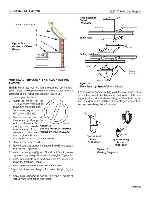
vent installation<br />
BLDV7 Series <strong>Gas</strong> Fireplace<br />
1 + 2 + 3 + 4 = 270°<br />
Attic Insulation<br />
Shield<br />
(7DV1AIS)<br />
Figure 24 -<br />
Maximum Elbow<br />
Usage<br />
1<br />
2<br />
3<br />
4<br />
1<br />
2<br />
3<br />
4<br />
Upper Flo<strong>or</strong><br />
11”<br />
(279 mm)<br />
12” Min.<br />
Ceiling Installation<br />
FP1029<br />
Joist<br />
FP1179<br />
VERTICAL THROUGH-THE-ROOF INSTAL-<br />
LATION<br />
NOTE: F<strong>or</strong> all top vent vertical through-the-roof installations,<br />
install the supplied cross-bar flue restrict<strong>or</strong> onto the<br />
top edge of the firebox flue adapter. Figure 25<br />
1. Locate your fireplace.<br />
2. Plumb to center of the<br />
(4”) flue collar from ceiling<br />
above and mark position.<br />
3. Cut opening equal to 9C\v” x<br />
9C\v” (248 x 248 mm).<br />
4. Proceed to plumb f<strong>or</strong> additional<br />
openings through the<br />
roof. In all cases, the<br />
opening must provide<br />
a minimum of 1 inch<br />
clearance to the vent<br />
FP2304<br />
pipe, i.e., the hole must<br />
be at least 9C\v” x 9C\v” (248 x 248 mm).<br />
FP2304<br />
Figure 25 -<br />
Vertical Through-the-Roof<br />
Restrict<strong>or</strong> (Part #69D3006)<br />
CDV7 top restrict<strong>or</strong><br />
5. Place fireplace into position. 3/09<br />
6. Place firestop(s) <strong>or</strong> Attic Insulation Shield into position<br />
and secure. Figure 26<br />
7. Install roof supp<strong>or</strong>t (Figure 27) and roof flashing making<br />
sure upper flange is below the shingles. Figure 29<br />
8. Install appropriate pipe sections until the venting is<br />
above the flashing. Figure 29<br />
9. Install st<strong>or</strong>m collar and seal around the pipe.<br />
10. Add additional vent lengths f<strong>or</strong> proper height. Figure<br />
28<br />
11. Apply high temperature sealant to 4” and 7” collars of<br />
vertical vent termination and install.<br />
Nails (4)<br />
Figure 26 -<br />
Place Firestop Spacer(s) and Secure<br />
Firestop<br />
Spacer<br />
If there is a room above ceiling level, fire stop spacer must<br />
be installed on both the FP1029 bottom ad the top side of the ceiling<br />
joists. If an attic is attic above insulation ceiling level shield an Attic Insulation<br />
Shield must be firestop installed. spacers The enlarged ends of the<br />
vent section always face 1/28/00 downward. djt<br />
Typical Roof<br />
Supp<strong>or</strong>t<br />
Application<br />
FP1184 Figure 27 -<br />
Venting Supp<strong>or</strong>ts<br />
Typical roof/ceiling<br />
supp<strong>or</strong>t apps.<br />
FP1184<br />
Typical Ceiling<br />
Supp<strong>or</strong>t<br />
Application<br />
20<br />
74D3000