Manual - Unvented Gas Log Heater or Vented Decorative Appliance
Manual - Unvented Gas Log Heater or Vented Decorative Appliance
Manual - Unvented Gas Log Heater or Vented Decorative Appliance

Create successful ePaper yourself
Turn your PDF publications into a flip-book with our unique Google optimized e-Paper software.
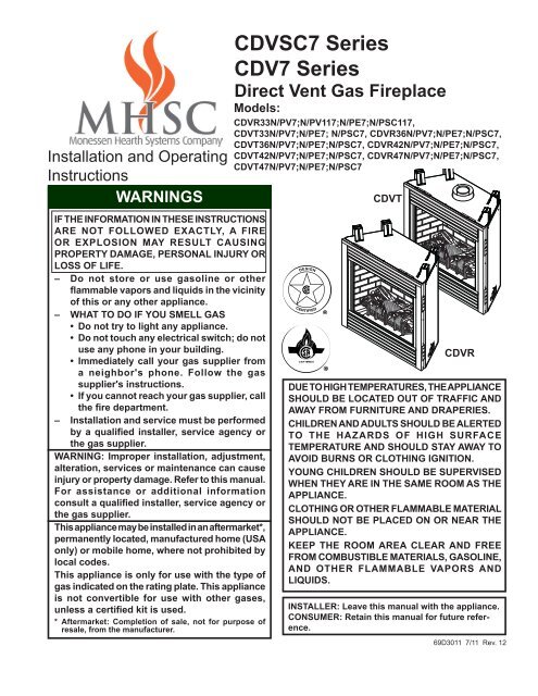
Installation and OperatingInstructionsWARNINGSIf the inf<strong>or</strong>mation in these instructionsare not followed exactly, a fire<strong>or</strong> explosion may result causingproperty damage, personal injury <strong>or</strong>loss of life.– Do not st<strong>or</strong>e <strong>or</strong> use gasoline <strong>or</strong> otherflammable vap<strong>or</strong>s and liquids in the vicinityof this <strong>or</strong> any other appliance.– WHAT TO DO IF YOU SMELL GAS• Do not try to light any appliance.• Do not touch any electrical switch; do notuse any phone in your building.• Immediately call your gas supplier froma neighb<strong>or</strong>'s phone. Follow the gassupplier's instructions.• If you cannot reach your gas supplier, callthe fire department.– Installation and service must be perf<strong>or</strong>medby a qualified installer, service agency <strong>or</strong>the gas supplier.WARNING: Improper installation, adjustment,alteration, services <strong>or</strong> maintenance can causeinjury <strong>or</strong> property damage. Refer to this manual.F<strong>or</strong> assistance <strong>or</strong> additional inf<strong>or</strong>mationconsult a qualified installer, service agency <strong>or</strong>the gas supplier.This appliance may be installed in an aftermarket*,permanently located, manufactured home (USAonly) <strong>or</strong> mobile home, where not prohibited bylocal codes.This appliance is only f<strong>or</strong> use with the type ofgas indicated on the rating plate. This applianceis not convertible f<strong>or</strong> use with other gases,unless a certified kit is used.* Aftermarket: Completion of sale, not f<strong>or</strong> purpose ofresale, from the manufacturer.CDVSC7 SeriesCDV7 SeriesDirect Vent <strong>Gas</strong> FireplaceModels:CDVR33n/pv7;N/PV117;n/pe7;N/PSC117,CDVT33n/Pv7;n/pe7; N/PSC7, CDVR36n/pv7;n/pe7;N/PSC7,CDVT36n/Pv7;n/pe7;N/PSC7, CDVR42n/pv7;n/pe7;N/PSC7,CDVT42n/Pv7;n/pe7;N/PSC7, CDVR47n/pv7;n/pe7;N/PSC7,CDVT47n/Pv7;n/pe7;N/PSC7CDVTCDVRDUE TO HIGH TEMPERATURES, THE APPLIANCESHOULD BE LOCATED OUT OF TRAFFIC ANDAWAY FROM FURNITURE AND DRAPERIES.CHILDREN AND ADULTS 693011 SHOULD BE ALERTEDTO THE HAZARDS CDVRT7 OF HIGH cover SURFACETEMPERATURE AND SHOULD STAY AWAY TOAVOID BURNS OR CLOTHING IGNITION.YOUNG CHILDREN SHOULD BE SUPERVISEDWHEN THEY ARE IN THE SAME ROOM AS THEAPPLIANCE.CLOTHING OR OTHER FLAMMABLE MATERIALSHOULD NOT BE PLACED ON OR NEAR THEAPPLIANCE.Keep the room area clear and freefrom combustible materials, gasoline,and other flammable vap<strong>or</strong>s andliquids.INSTALLER: Leave this manual with the appliance.CONSUMER: Retain this manual f<strong>or</strong> future reference.69D3011 7/11 Rev. 12
CDVSC7 & CDV7 Series <strong>Gas</strong> FireplaceCONTENTSPLEASE READ THE INSTALLATION & OPERATING INSTRUCTIONS BEFORE USING APPLIANCE.Thank you and congratulations on your purchase of a MHSC fireplace.IMPORTANT: Read all instructions and warnings carefully bef<strong>or</strong>e starting installation.Failure to follow these instructions fully may result in a possible fire hazard and will void the warranty.Imp<strong>or</strong>tant Safety Inf<strong>or</strong>mation..................................... 3Code Approval............................................................. 4Product Specifications............................................... 5High Elevations....................................................... 6<strong>Gas</strong> Pressures........................................................ 6<strong>Gas</strong> Specifications, Orifice Sizes............................ 6Fireplace & Framing Dimensions........................... 7Pre-Installation Inf<strong>or</strong>mationBef<strong>or</strong>e You Start..................................................... 9Fireplace Framing .................................................. 9Fireplace Location................................................ 10Clearances..................................................................11Securing Fireplace to Flo<strong>or</strong> <strong>or</strong> Framing.................. 12Finishing Material................................................. 12Venting Installation................................................... 13General VentingTermination Location...................................... 13Termination Clearances................................. 15Assembling Vent Pipes.................................. 15Rear Vent Installation Only............................. 16How to Use the Vent Graph........................... 17Vent Pipe Clearances..................................... 18Rear Vent Applications & Installation.................... 19Top Vent Sidewall Applications & Installation....... 20Vertical Sidewall Applications & Installation.......... 22Below Grade Installation....................................... 24Vertical Through-the-RoofApplications & Installation.............................. 25Fireplace Installation................................................ 27Check <strong>Gas</strong> Type................................................... 27<strong>Gas</strong> Pipe Installation............................................. 28Check <strong>Gas</strong> Pressure - Millivolt................................ 29Electrical Installation................................................ 29Electrical Wiring................................................. 29Remote Wall Mounted Switch............................... 30Remote Wall Switch.............................................. 30Optional DC Remote Systems.............................. 30Electronic Pilot Ignition Wiring.............................. 31Optional Fan/Blower Systems.............................. 31Operating Instructions - Millivolt............................. 32What To Do If You Smell <strong>Gas</strong>............................... 32Lighting Pilot f<strong>or</strong> the First Time............................. 32Lighting Pilot......................................................... 33Lighting Burner..................................................... 34To Turn Off <strong>Gas</strong>.................................................... 34Operating Instructions Electronic Ignition............. 35What To Do If You Smell <strong>Gas</strong>............................... 35Lighting Electronic Ignition.................................... 35To Turn Off <strong>Gas</strong>.................................................... 35Check <strong>Gas</strong> Pressure - Signature Command System 36Electrical Installation - SCS..................................... 36Electrical Wiring.................................................... 36Junction Box Wiring.............................................. 37Command Center Wall Installation....................... 37Wall Switch Installation......................................... 37Signature Command System Wiring Diagram...... 38Optional Fan/Blower System - SCS......................... 39BLOTSC Wiring Diagram..................................... 39BLOT Automotic Thermostat Blower.................... 40FK-12 <strong>Manual</strong> Blower........................................... 40Operating Instructions - SCS................................... 41What To Do If You Smell <strong>Gas</strong>............................... 41Operating Instructions.......................................... 42To Turn Off <strong>Gas</strong>.................................................... 42Signature Command System................................... 43Operation Instructions.......................................... 43Glass Removal.......................................................... 46<strong>Log</strong> Placement.......................................................... 46Rockwool Placement............................................ 46<strong>Log</strong> Placement...................................................... 47Lava Rock and Ember Placement........................ 47Cleaning and Maintenance....................................... 48Burner, Pilot and Control Compartment................ 48Pilot Flame............................................................ 48Burner Flame........................................................ 48Vent System......................................................... 49Glass Do<strong>or</strong>............................................................ 49<strong>Log</strong>s...................................................................... 49Rock Wool ........................................................... 49Troubleshooting........................................................ 50Replacement Parts.................................................... 54Firebox Components............................................ 54Standing Pilot - Millivolt Control............................ 56Electronic Ignition................................................. 58Signature Command System................................ 59<strong>Log</strong>s...................................................................... 61Venting Components............................................ 62Massachusetts Requirements................................. 66Warranty..................................................................... 67Energuide Efficiencies............................................. 6869D3011
IMPORTANT SAFETY INFORMATIONINSTALLERPlease leave these instructions with the appliance.OWNERCDVSC7 & CDV7 Series <strong>Gas</strong> FireplacePlease retain these instructions f<strong>or</strong> future reference.WARNING• Read this owner’s manual carefully and completely bef<strong>or</strong>e trying to assemble, operate,<strong>or</strong> service this fireplace.• Any change to this fireplace <strong>or</strong> its controls can be dangerous.• Improper installation <strong>or</strong> use of this fireplace can cause serious injury <strong>or</strong> death fromfire, burns, explosions, electrical shock and carbon monoxide poisoning.This fireplace is a vented product. This fireplace mustbe properly installed by a qualified service person. Theglass do<strong>or</strong> must be properly seated and sealed. If thisunit is not properly installed by a qualified service personwith glass do<strong>or</strong> properly seated and sealed, combustionleakage can occur.CARBON MONOXIDE POISONING: Early signs ofcarbon monoxide poisoning are similar to the flu withheadaches, dizziness and/<strong>or</strong> nausea. If you have thesesigns, the fireplace may not have been installed properly.Get fresh air at once! Have the fireplace inspected andserviced by a qualified service person. Some people arem<strong>or</strong>e affected by carbon monoxide than others. Theseinclude pregnant women, people with heart <strong>or</strong> lung disease<strong>or</strong> anemia, those under the influence of alcohol, andthose at high altitudes.Propane/LP gas and natural gas are both od<strong>or</strong>less. Anod<strong>or</strong>-making agent is added to each of these gases. Theod<strong>or</strong> helps you detect a gas leak. However, the od<strong>or</strong>added to these gases can fade. <strong>Gas</strong> may be present eventhough no od<strong>or</strong> exists.Make certain you read and understand all warnings. Keepthis manual f<strong>or</strong> reference. It is your guide to safe andproper operation of this fireplace.1. This appliance is only f<strong>or</strong> use with the type of gasindicated on the rating plate. This appliance is notconvertible f<strong>or</strong> use with other gases unless a certifiedkit is used.2. F<strong>or</strong> propane/LP fireplace, do not place propane/LPsupply tank(s) inside any structure. Locate propane/LP supply tank(s) outdo<strong>or</strong>s. To prevent perf<strong>or</strong>manceproblems, do not use propane/LP fuel tank of lessthan 100 lbs. capacity.3. If you smell gas• shut off gas supply.• do not try to light any appliance.• do not touch any electrical switch; do not use anyphone in your building .• immediately call your gas supplier from a neighb<strong>or</strong>’sphone. Follow the gas supplier’s instructions.69D30114. Never install the fireplace• in a recreational vehicle• where curtains, furniture, clothing, <strong>or</strong> other flammableobjects are less than 42" from the front, top,<strong>or</strong> sides of the fireplace• in high traffic areas• in windy <strong>or</strong> drafty areas5. This fireplace reaches high temperatures. Keep childrenand adults away from hot surfaces to avoid burns <strong>or</strong>clothing ignition. Fireplace will remain hot f<strong>or</strong> a time aftershutdown. Allow surfaces to cool bef<strong>or</strong>e touching.6. Young children should be carefully supervised whenthey are in the same room as the appliance. Toddlers,young children and others may be susceptible to accidentalcontact burns. A physical barrier is recommendedif there are at risk individuals in the house. To restrictaccess to a fireplace <strong>or</strong> stove, install an adjustablesafety gate to keep toddlers, young children and otherat risk individuals out of the room and away from hotsurfaces.7. Do not modify fireplace under any circumstances. Anyparts removed f<strong>or</strong> servicing must be replaced pri<strong>or</strong> tooperating fireplace.8. Turn fireplace off and let cool bef<strong>or</strong>e servicing, installing,<strong>or</strong> repairing. Only a qualified service person shouldinstall, service, <strong>or</strong> repair the fireplace. Have burnersystem inspected annually by a qualified serviceperson.9. You must keep control compartments, burners, andcirculating air passages clean. M<strong>or</strong>e frequent cleaningmay be needed due to excessive lint and dust. Turn offthe gas valve and pilot light bef<strong>or</strong>e cleaning fireplace.10. Have venting system inspected annually by a qualifiedservice person. If needed, have venting systemcleaned <strong>or</strong> repaired. See Cleaning and Maintenance,Page 48.11. Keep the area around your fireplace clear of combustiblematerials, gasoline, and other flammable vap<strong>or</strong> andliquids. Do not run fireplace where these are used <strong>or</strong>st<strong>or</strong>ed. Do not place items such as clothing <strong>or</strong> dec<strong>or</strong>ationson <strong>or</strong> around fireplace.Continued on page 4
!CDVSC7 & CDV7 Series <strong>Gas</strong> Fireplace12. Do not use this fireplace to cook food <strong>or</strong> burn paper <strong>or</strong>other objects.13. Never place anything on top of fireplace.14. Do not use any solid fuels (wood, coal, paper, cardboard,etc.) in this fireplace. Use only the gas typeindicated on rating plate.15. This appliance, when installed, must be electricallygrounded in acc<strong>or</strong>dance with local codes <strong>or</strong> in theabsence of local codes, with the National ElectricalCode, ANSI/NFPA 70, <strong>or</strong> the Canadian Electrical Code,CSA C22.1.16. Do not obstruct the flow of combustion and ventilationair in any way. Provide adequate clearances aroundair openings into the combustion chamber along withadequate accessibility clearance f<strong>or</strong> servicing andproper operation.17. When the appliance is installed directly on carpeting,tile <strong>or</strong> other combustible material other than woodflo<strong>or</strong>ing, you must set appliance on a metal <strong>or</strong> woodpanel <strong>or</strong> hearth pad extending the full width and depthof the appliance.18. Do not use fireplace if any part has been exposed to<strong>or</strong> has been under water. Immediately call a qualifiedservice person to arrange f<strong>or</strong> replacement of theunit.19. Do not operate fireplace if any log is broken.20. Do not use a blower insert, heat exchanger insert, <strong>or</strong>any other access<strong>or</strong>y not approved f<strong>or</strong> use with thisfireplace.21. Do not operate the fireplace with glass do<strong>or</strong> removed,cracked, <strong>or</strong> broken.Code ApprovalDirect Vent type appliances draw all combustion air fromoutside of the dwelling through the vent pipe.These appliances have been tested by CSA and foundto comply with the established standards in the USA andCanada as follows:LISTED VENTED GAS FIREPLACE HEATERTESTED TO (latest edition):CDVR: ANSI Z21.88 / CSA 2.33 STANDARDSLISTED VENTED GAS FIREPLACECDVT: ANSI Z21.50 CSA 2.22 STANDARDSA manufactured home (USA only) <strong>or</strong> mobile home OEMinstallation must conf<strong>or</strong>m with the Manufactured HomeConstruction and Safety Standard, Title 24 CFR, Part3280, <strong>or</strong> when such a standard is not applicable, theStandard f<strong>or</strong> Manufactured Home Installations, ANSI/NCSBCS A225.1, <strong>or</strong> Standard f<strong>or</strong> <strong>Gas</strong> Equipped RecreationalVehicles and Mobile Housing, CSA Z240.4.IMPORTANT SAFETY INFORMATIONIMPORTANT:PLEASE READ THE FOLLOWING CAREFULLYIt is n<strong>or</strong>mal f<strong>or</strong> fireplaces fabricated of steelto give off some expansion and/<strong>or</strong> contractionnoises during the start up <strong>or</strong> cool down cycle.Similar noises are found with your furnace heatexchanger <strong>or</strong> car engine.IMPORTANT:PLEASE READ THE FOLLOWING CAREFULLYIt is not unusual f<strong>or</strong> gas fireplace to give off someod<strong>or</strong> the first time it is burned. This is due to themanufacturing process.Please ensure that your room is wellventilated during burn off — open allwindows.It is recommended that you burn your fireplacef<strong>or</strong> at least ten (10) hours the first time you use it.Place the fan switch in the “OFF” position duringthis time.WARNINGNever connect unit to private (non-utility)gas wells. This gas is commonly knownas wellhead Nous gas. recommandons que nosappareils de chauffage au gazsoient installés et entretenus pardes professionnels qui ont étéaccrédités aux È.U. par le NationalFireplace Institute ® (NFI) comme!étantWARNINGdes spécialistes du NFI enmatièred’appareils HOT GLASS de chauffage WILLau gaz. CAUSE BURNS.DO NOT TOUCH GLASSUNTIL COOLED.NEVER ALLOW CHILDRENTO TOUCH GLASS.69D3011
product featuresCDVSC7 & CDV7 Series <strong>Gas</strong> Fireplaceproduct SPECIFICATIONS• This appliance has been certified f<strong>or</strong> use with eithernatural <strong>or</strong> propane gas. See appropriate data plates.• This appliance is not f<strong>or</strong> use with solid fuels.• The appliance is approved f<strong>or</strong> bedroom <strong>or</strong> bedsittingroom installations.• The appliance must be installed in acc<strong>or</strong>dance with localcodes if any. If none exist use the current installationcode. ANSI Z223.1/NFPA 54 in the USA, CSA B149 inCanada.• This appliance is mobile home approved.• The appliance must be properly connected to a ventingsystem.• The appliance is not approved f<strong>or</strong> closet installations.• This appliance is approved to be vented with Simpson-Duravent and MHSC Twist-Lock Direct Vent Components.Remote ControlSwitch ReceiverHi/Lo KnobOff/Pilot/On KnobIgnit<strong>or</strong>Figure 1 -CDV7 Series FireplaceOn/Off/RSSwitchBlowerControlFP2284The classification “noncombustible material” includes, butis not limited to stone, brick and m<strong>or</strong>tar. Noncombustiblesare safe to overlay the black-painted metal face (includingradiant plates) and do not pose a fire hazard. Do notallow any noncombustible finish material to extend past <strong>or</strong>interfere with fireplace opening.The classification “combustible material” includes, but is notlimited to plywood, drywall and particle board. Combustiblematerials may contact the sides, bottom <strong>or</strong> back of firebox.Do not overlay the black painted face with combustiblematerials.FP2284aCDV7 controls69D3011
CDVSC7 & CDV7 Series <strong>Gas</strong> FireplaceHIGH ELEVATIONSInput ratings are shown in BTU per hour and are certifiedwithout deration f<strong>or</strong> elevations up to 4,500 feet (1,370m) above sea level.F<strong>or</strong> elevations above 4,500 feet (1,370 m) in USA,installations must be in acc<strong>or</strong>dance with the currentANSI Z223.1/NFPA 54 and/<strong>or</strong> local codes having jurisdiction.In Canada, please consult provincial and/<strong>or</strong> local auth<strong>or</strong>itieshaving jurisdiction f<strong>or</strong> installations at elevationsabove 4,500 feet (1,370 m).GAS SPECIFICATIONS & ORIFICE SIZECDVR SERIESMax.Input Min. Input OrificeModel Fuel BTU/h BTU/h SizeCDVR33NV7 Nat. 18,000 13,000 #45CDVR33NV117 Nat. 18,000 13,000 #45CDVR33NE7 Nat. 18,000 13,000 #45CDVR33NSC117 Nat. 18,000 13,000 #45CDVR36NV7 Nat. 20,000 15,000 #44CDVR36NE7 Nat. 20,000 15,000 #44CDVR36NSC7 Nat. 20,000 15,000 #44CDVR42NV7 Nat. 24,000 17,000 2.35 mmCDVR42NE7 Nat. 24,000 17,000 2.35 mmCDVR42NSC7 Nat. 24,000 17,000 2.35 mmCDVR47NV7 Nat. 24,000 17,000 2.35 mmCDVR47NE7 Nat. 24,000 17,000 2.35 mmCDVR47NSC7 Nat. 24,000 17,000 2.35 mmCDVR33PV7 LP 18,000 13,000 1.28 mmCDVR33PV117 LP 17,000 14,000 1.25 mmCDVR33PE7 LP 18,000 13,000 1.28 mmCDVR33PSC117 LP 17,000 14,000 1.25 mmCDVR36PV7 LP 20,000 15,000 1.35 mmCDVR36PE7 LP 20,000 15,000 1.35 mmCDVR36PSC7 LP 20,000 15,000 1.35 mmCDVR42PV7 LP 24,000 18,000 1.45 mmCDVR42PE7 LP 24,000 18,000 1.45 mmCDVR42PSC7 LP 24,000 18,000 1.45 mmCDVR47PV7 LP 24,000 18,000 1.45 mmCDVR47PE7 LP 24,000 18,000 1.45 mmCDVR47PSC7 LP 24,000 18,000 1.45 mmproduct features & <strong>Gas</strong> specificationsGAS pressuresNatural Propane (LP)Inlet Minimum 5.5” w.c. 11.0” w.c.Inlet Maximum 14.0” w.c. 14.0” w.c.Manifold Pressure 3.5” w.c. 10.0” w.c.GAS SPECIFICATIONS & ORIFICE SIZECDVT SERIESMax.Input Min. Input OrificeModel Fuel BTU/h BTU/h SizeCDVT33NV7 Nat. 18,000 13,000 #45CDVT33PV7 LP 18,000 13,000 1.28 mmCDVT33NE7 Nat. 18,000 13,000 #45CDVT33PE7 LP 18,000 13,000 1.28 mmCDVT33NSC7 Nat. 18,000 13,000 #45CDVT33PSC7 LP 18,000 13,000 1.28 mmCDVT36NV7 Nat. 20,000 15,000 #44CDVT36PV7 LP 20,000 15,000 1.35 mmCDVT36NE7 Nat. 20,000 15,000 #44CDVT36PE7 LP 20,000 15,000 1.35 mmCDVT36NSC7 Nat. 20,000 15,000 #44CDVT36PSC7 LP 20,000 15,000 1.35 mmCDVT42NV7 Nat. 24,000 17,000 2.35 mmCDVT42PV7 LP 24,000 18,000 1.45 mmCDVT42NE7 Nat. 24,000 17,000 2.35 mmCDVT42PE7 LP 24,000 18,000 1.45 mmCDVT42NSC7 Nat. 24,000 17,000 2.35 mmCDVT42PSC7 LP 24,000 18,000 1.45 mmCDVT47NV7 Nat. 24,000 17,000 2.35 mmCDVT47PV7 LP 24,000 18,000 1.45 mmCDVT47NE7 Nat. 24,000 17,000 2.35 mmCDVT47PE7 LP 24,000 18,000 1.45 mmCDVT47NSC7 Nat. 24,000 17,000 2.35 mmCDVT47PSC7 LP 24,000 18,000 1.45 mm69D3011
fireplace dimensions & FRAMINGCDVSC7 & CDV7 Series <strong>Gas</strong> FireplaceGMinimum RoughOpeningDepthM1/2” <strong>or</strong> 5/8”5/8”1/2”5/8”1/2”FOLNMP - Minimum Rough Opening WidthMinimum RoughOpeningHeight1”5/8”Q1/2”C LDECHB1/2”15/16”Figure 2 -CDVR Series Fireplace DimensionsIAJK5/8”NOTE: Models CDVR33SC7 & CDVR33V117have no standoffs on top of unit.CDVR33(V)(SC)117 CDVR33(V,E)7 CDVR36(V,E,SC)7 CDVR42(V,E,SC)7 CDVR47(V,E,SC)7A 33C\," (848 mm) 33" (838 mm) 37Z\zn" (941 mm) 41" (1041 mm) 47" (1194 mm)B see note 35B\," (905 mm) 38B\," (981 mm) 38B\," (981 mm) 38B\," (981 mm)693011CDVR7 DIMSC 31ZZ\zn" (805 mm) 31ZZ\zn" (805 mm) 34>\zn" (878 mm) 34>\zn" (878 mm) 34>\zn" (878 mm)D 27C\zn" (691 mm) 27C\zn" (691 mm) 29Z\zn" (738 mm) 33Z\zn" (840 mm) 39Z\zn" (992 mm)E 15C\zn" (386 mm) 15C\zn" (386 mm) 20C\," (518 mm) 20C\," (518 mm) 20C\," (518 mm)F 11C\v" (299 mm) 14C\zn" (360 mm) 15C\v" (400 mm) 15C\v" (400 mm) 15C\v" (400 mm)G 21Z\x" (546 mm) 21C\," (546 mm) 21M\," (556 mm) 25M\," (657 mm) 31M\," (810 mm)H 21ZB\zn" (557 mm) 21ZB\zn" (557 mm) 25Z\v" (641 mm) 25Z\v" (641 mm) 25Z\v" (641 mm)I 29M\," (759 mm) 29M\," (759 mm) 32" (813 mm) 36" (914 mm) 42" (1067 mm)J 2B\zn" (59 mm) 2B\zn" (59 mm) 2C\," (60 mm) 2C\," (60 mm) 2C\," (60 mm)K 5" (127 mm) 7C\zn" (183 mm) 5M\zn" (138 mm) 5M\zn" (138 mm) 5M\zn" (138 mm)Framing DimensionsL 51" (1295 mm) 48C\v" (1238 mm) 52M\zn" (1332 mm) 56M\zn" (1434 mm) 62M\zn" (1586 mm)M 36" (914 mm) 34Z\x" (876 mm) 37Z\zn" (941 mm) 40" (1016 mm) 44Z\," (1121 mm)N 25Z\x" (648 mm) 24C\," (619 mm) 26Z\v" (667 mm) 28Z\v" (718 mm) 31Z\v" (794 mm)O 11Z\v" (286 mm) 13ZZ\zn" (347 mm) 15Z\v" (387 mm) 15Z\v" (387 mm) 15Z\v" (387 mm)P 33B\," (854 mm) 33Z\v" (845 mm) 37Z\x" (953 mm) 41Z\v" (1048 mm) 47Z\v" (1200 mm)Q 32Z\v" (819 mm) 35M\," (911 mm) 39" (991 mm) 39" (991 mm) 39" (991 mm)69D3011
CDVSC7 & CDV7 Series <strong>Gas</strong> Fireplacefireplace dimensions & FRAMINGHGMinimum RoughOpeningDepthN1/2” <strong>or</strong> 5/8”I5/8”1/2”5/8”1/2”FPMONQ - Minimum Rough Opening WidthMinimum RoughOpeningHeight1”5/8”R1/2”DECB1/2”15/16”Figure 3 -CDVT Series Fireplace DimensionsAJCDVT33(V,E,SC)7 CDVT36 (V,E,SC)7 CDVT42 (V,E,SC)7 CDVT47 (V,E,SC)7A 33" (38 mm) 37Z\zn" (941 mm) 41" (1041 mm) 47" (1194 mm)B 35B\," (905 mm) 38B\," (981 mm) 38B\," (981 mm) 38B\," (981 mm)C 31ZZ\zn" (805 mm) 34>\zn" (878 mm) 34>\zn" (878 mm) 34>\zn" (878 mm)693011CDVT7 top dimsD 27C\zn" (691 mm) 29Z\zn" (738 mm) 33Z\zn" (840 mm) 39Z\zn" (992 mm)E 15C\zn" (386 mm) 20C\," (518 mm) 20C\," (518 mm) 20C\," (518 mm)F 14C\zn" (360 mm) 15C\v" (400 mm) 15C\v" (400 mm) 15C\v" (400 mm)G 21C\," (546 mm) 21M\," (556 mm) 25M\," (657 mm) 31M\," (810 mm)H 10ZZ\zn" (272 mm) 10ZB\zn" (278 mm) 12ZB\zn" (329 mm) 15ZB\zn" (405 mm)I 6Z\x" (165 mm) 6Z\x" (165 mm) 6Z\x" (165 mm) 6Z\x" (165 mm)J 29M\," (759 mm) 32" (813 mm) 36" (914 mm) 42" (1067 mm)K 2B\zn" (59 mm) 2C\," (60 mm) 2C\," (60 mm) 2C\," (60 mm)L 7C\zn" (183 mm) 5M\zn" (138 mm) 5M\zn" (138 mm) 5M\zn" (138 mm)Framing DimensionsM 48C\v" (1238 mm) 52M\zn" (1332 mm) 56M\zn" (1434 mm) 62M\zn" (1586 mm)N 34Z\x" (876 mm) 37Z\zn" (941 mm) 40" (1016 mm) 44Z\," (1121 mm)O 24C\," (619 mm) 26Z\v" (667 mm) 28Z\v" (718 mm) 31Z\v" (794 mm)P 13ZZ\zn" (347 mm) 15Z\v" (387 mm) 15Z\v" (387 mm) 15Z\v" (387 mm)Q 33Z\v" (845 mm) 37Z\x" (953 mm) 41Z\v" (1048 mm) 47Z\v" (1200 mm)R 35M\," (911 mm) 39" (991 mm) 39" (991 mm) 39" (991 mm)KL5/8”69D3011
pRE-INSTALLATION INFORMATIONBef<strong>or</strong>e You StartRead this homeowner manual th<strong>or</strong>oughly and follow allinstructions carefully. Inspect all contents f<strong>or</strong> shippingdamage and immediately inf<strong>or</strong>m your dealer if any damageis found. Do not install any unit with damaged, incomplete,<strong>or</strong> substitute parts. Check your packing list to verify thatall listed parts have been received. You should have thefollowing:• Fireplace (Firebox and Burner System)• <strong>Log</strong> Set• Volcanic Rock• Rock WoolItems Required F<strong>or</strong> InstallationTools:Building Supplies:• Phillips Screwdriver • Framing Materials• Hammer• Wall Finishing Materials• Saw and/<strong>or</strong> saber saw • Level• Electric Drill and Bits • Tee Joint• Pliers• Measuring Tape• Square• Pipe Wrench• Caulking Material (Noncombustible)• Fireplace Surround Material (Noncombustible)• Piping Complying with Local Codes• Pipe Sealant Approved f<strong>or</strong> use with Propane/LPG(Resistant to Sulfur Compounds)CDVSC7 & CDV7 Series <strong>Gas</strong> Fireplacefirebox framing FOR CDVRFirebox framing can be built bef<strong>or</strong>e <strong>or</strong> after the appliance isset in place. Construct firebox framing following Figure 2 f<strong>or</strong>your specific installation requirements. Refer to Figure 2 f<strong>or</strong>firebox dimensions. The framing headers may rest on thetop of the firebox standoffs. Do not bring headers belowtop of standoffs. NOTE: CDVR33SC7 & CDVR33117 donot have standoffs.The firebox may be installed directly on a combustible flo<strong>or</strong><strong>or</strong> raised on a platf<strong>or</strong>m of an appropriate height. Whenthe firebox is installed directly on carpeting, tile, <strong>or</strong> othercombustible material, other than wood flo<strong>or</strong>ing, the fireboxshall be installed on a metal <strong>or</strong> wood panel extending thefull width and depth of the enclosure.firebox framing FOR CDVTFirebox framing can be built bef<strong>or</strong>e <strong>or</strong> after the applianceis set in place. Construct firebox framing following Figure 3f<strong>or</strong> your specific installation requirements. Refer to Figure3 f<strong>or</strong> firebox dimensions. The framing headers may reston the top of the firebox standoffs. Do not bring headersbelow top of standoffs.The firebox may be installed directly on a combustible flo<strong>or</strong><strong>or</strong> raised on a platf<strong>or</strong>m of an appropriate height. Whenthe firebox is installed directly on carpeting, tile, <strong>or</strong> othercombustible material, other than wood flo<strong>or</strong>ing, the fireboxshall be installed on a metal <strong>or</strong> wood panel extending thefull width and depth of the enclosure.WARNINGDo not fill spaces around firebox withinsulation <strong>or</strong> other materials. This couldcause a fire.NOTECOLD CLIMATE INSULATIONIf you live in a cold climate, seal all cracks around your appliance, andwherever cold air could enter the room, with noncombustible material.It is especially imp<strong>or</strong>tant to insulate the outside chase cavity betweenthe studs and under the flo<strong>or</strong> on which the appliance rests, if the flo<strong>or</strong>is above ground level.69D3011
CDVSC7 & CDV7 Series <strong>Gas</strong> FireplacepRE-INSTALLATION INFORMATIONFireplace LocationPlan f<strong>or</strong> the installation of your appliance. This includes determining where the unit is to be installed,the vent configuration to be used, framing and finishing details, and whether any optional access<strong>or</strong>ies(i.e. blower, wall switch, <strong>or</strong> remote control) are desired. Consult your local building code agency toensure compliance with local codes, including permits and inspections.The following fact<strong>or</strong>s should be taken into consideration:• Clearance to side-wall, ceiling, woodw<strong>or</strong>k, and windows. Minimum clearances to combustiblesmust be maintained.• This fireplace may be installed along a wall, across a c<strong>or</strong>ner, <strong>or</strong> use an exteri<strong>or</strong> chase. Refer toFigure 4 f<strong>or</strong> suggested locations.• Location should be out of high traffic areas and away from furniture and draperies due to heatfrom appliance.• Never obstruct the front opening of the fireplace.• Do not install in the vicinity where gasoline <strong>or</strong> other flammable liquids may be st<strong>or</strong>ed.• Vent pipe routing. See Venting section found in this manual f<strong>or</strong> allowable venting configurations.• These units can be installed in a bedroom. See National Fuel <strong>Gas</strong> Code ANSI Z233.1/NFPA 54— (current edition), the Unif<strong>or</strong>m Mechanical Code — (current edition), and Local Building Codesf<strong>or</strong> specific installation requirements.YYEDFABXCBFigure 4 -LU584-1Locating <strong>Gas</strong> Fireplace Locating unit2/4/99 djtABCDEFYFlat on WallCross C<strong>or</strong>nerIsland**Room Divider*Flat on Wall C<strong>or</strong>ner*Chase Installation4" Minimum** Island (C) and room divider (D) installation is possible as longas the h<strong>or</strong>izontal p<strong>or</strong>tion of vent system (X) does not exceed20'.* When you install your fireplace in (D) room divider <strong>or</strong> (E)flat on wall c<strong>or</strong>ner positions (Y), a minimum of 4" clearancemust be maintained from perpendicular wall and front offireplace.10 69D3011
CLEARANCESCDVSC7 & CDV7 Series <strong>Gas</strong> FireplaceClearances to combustiblesWARNINGFollow these instructions carefully toensure safe installation. Failure to followinstructions exactly can create a firehazard.The appliance cannot be installed on acarpet, tile <strong>or</strong> other combustible materialother than wood flo<strong>or</strong>ing. If installed oncarpet <strong>or</strong> vinyl flo<strong>or</strong>ing, the applianceshall be installed on a metal, wood <strong>or</strong>noncombustible material panel extendingfull width and depth of the appliance.Finish Wall12” (305 mm)8” (203 mm)A6” (152 mm)B 2”(64 mm)CDStudHeaderStandoffCeiling72"MinimumSideWallTop of HeatExhaust VentCDV33/36/42/47Side ViewFP2285bNOTE: CDVR33SC7 & CDVR33117have no standoffs.Ref. CDV33 CDV36 CDV42/47AB14" (356 mm) FP2285b 12" (305 mm)11" (279 mm) mantel 11" clearances (279 mm)12" (305 mm)9Z\x" (241 mm)C 10" (254 mm) 10" (254 mm) 8Z\x" (216 mm)D 8" (203 mm) 8" (203 mm) 6" (152 mm)Stud6”MinimumFigure 5 -Ceiling and Side Wall Clearancesmantel clearancesfP2032wall clearancesFP2032NOTE: The combustible area above the facing mustnot protrude m<strong>or</strong>e than 3/4" from the facing. If it does,it is considered a mantel and must meet the mantelrequirements listed in this manual.NOTE: The MHSC Barrington Cabinet Mantel Model seriesBWC300, BWC400 and BWC500 are specially designedto comply with all mantel temperature requirements. Anycustom-built mantel must comply with all clearance requirementsshown in this instruction manual.WARNINGFP2286Side of FireplaceOpeningFront ViewFigure 6 -Mantel Clearances1" 1”3”2”4”3" 45°5"FP2286Mantel leg clearNever obstruct <strong>or</strong> modify the air inlet <strong>or</strong>outlet grilles (louvers). This may createa fire hazard.6"WallCombustibleMaterial Area69D3011 11
CDVSC7 & CDV7 Series <strong>Gas</strong> FireplaceSECURE FIREPLACE to flo<strong>or</strong> <strong>or</strong> framingThe fireplace must be secured to theflo<strong>or</strong> and/<strong>or</strong> to framing studs as shownin Figure 7. Use two (2) wood screws<strong>or</strong> masonry/ concrete screws to securefireplace to the flo<strong>or</strong>. Use four (4) screwsto attach fireplace to framing. The sidenailing flanges are 1/2" <strong>or</strong> 5/8" to accommodatedifferent wall thickness.FramingNailingFlangeDrywall Supp<strong>or</strong>t Tabs (DoNot Use f<strong>or</strong> Framing <strong>or</strong>Header)ScrewsFramingNailingFlangeScrewScrewNailingFlangesFigure 7 -Securing Fireplace to Flo<strong>or</strong> andFraming Studs (CDVT36 shown)ScrewScrewFP2287Finishing MaterialNOTE: Any wiring (i.e. remote control, wall switch, and optional fan) must be done pri<strong>or</strong> to finalfinishing to avoid costly reconstruction.FP2287secure fireplaceOnly noncombustible materials (i.e. brick, tile, slate, steel, <strong>or</strong> other materials with a UL fire ratingof Zero) may be used to cover the black surface of the appliance. A 300°F minimum adhesivemay be used to attach facing materials to the black surface. If joints between the finished walland the fireplace surround are sealed, a 300°F minimum sealant material (General ElectricRTV103 <strong>or</strong> equivalent) must be used.12 69D3011
Venting INSTALLATION INFORMATIONCDVSC7 & CDV7 Series <strong>Gas</strong> FireplaceWARNINGRead all instructions completely and th<strong>or</strong>oughly bef<strong>or</strong>e attempting installation. Failureto do so could result in serious injury, property damage <strong>or</strong> loss of life. Operation ofimproperly installed and maintained venting system could result in serious injury,property damage <strong>or</strong> loss of life.installation precautionsConsult local building codes bef<strong>or</strong>e beginning theinstallation. The installer must make sure to select theproper vent system f<strong>or</strong> installation. Bef<strong>or</strong>e installing ventkit, the installer must read this fireplace manual and ventkit instructions.Only a qualified installer/service person should install ventingsystem. The installer must follow these safety rules:• Wear gloves and safety glasses f<strong>or</strong> protection.• Use extreme caution when using ladders <strong>or</strong> when onrooftops.• Be aware of electrical wiring locations in walls andceilings.The following actions will void the warranty on your ventingsystem:• Installation of any damaged venting component.• Unauth<strong>or</strong>ized modification of the venting system.• Installation of any component part not manufactured<strong>or</strong> approved by MHSC.• Installation other than permitted by these instructions.WARNINGWARNINGThis fireplace must be vented to theoutside. The venting system must NEVERbe attached to a chimney serving a separatesolid fuel burning appliance. Each gasappliance must use a separate vent system.Do not use common vent systems.Always maintain minimum clearances aroundvent systems. The minimum clearances tocombustibles f<strong>or</strong> h<strong>or</strong>izontal vent pipe are 3"at the top* and 1" at the sides and bottomof the vent system until the pipe penetratesthe nearest vertical wall (1" required). A 1"minimum clearance all around the pipe mustbe maintained at outside wall and on verticalruns. Do not pack the open air spaces withinsulation <strong>or</strong> other materials. This couldcause high temperatures and may presenta fire hazard.* Unless the vertical run is 7Z\x feet <strong>or</strong> higher(top vent units only), the clearances f<strong>or</strong> theh<strong>or</strong>izontal run is 1" at the top.General VentingYour fireplace is approved to be vented either through theside wall, <strong>or</strong> vertical through the roof.• Only MHSC venting components specifically approvedand labelled f<strong>or</strong> this fireplace may be used.• Flexible UL1777 listed venting may be used in any ventingapplication where rigid direct vent components canbe used. All restrictions, clearances and allowances thatpertain to the rigid piping apply to the flexible venting.Flex kits may not be modified. Flex kits may be added tothe end of a vent run made of rigid vent sections usingpipe manufacturer's approved flex to pipe adapters. Thismay occur only if doing so does not violate any of theventing length, height, routing, h<strong>or</strong>izontal to vertical rait<strong>or</strong>equirements <strong>or</strong> clearance considerations detailed in thismanual.• Venting terminals shall not be recessed into a wall <strong>or</strong> siding.• Select the amount of vertical rise desired. All h<strong>or</strong>izontalrun of venting must have 1/4" rise f<strong>or</strong> every 12" of runtowards the termination below 7 1 /2 feet of vertical rise.With 7 1 /2 feet <strong>or</strong> m<strong>or</strong>e vertical rise off top of fireplace,the h<strong>or</strong>izontal run may run level. NEVER run vent pipingdownward.• H<strong>or</strong>izontal venting which inc<strong>or</strong>p<strong>or</strong>ates the twist lock pipemust be installed on a level plane without an inclining <strong>or</strong>declining slope.• H<strong>or</strong>izontal venting which inc<strong>or</strong>p<strong>or</strong>ates the use of flexventing shall have an inclining slope from the unit of 1”(25 mm) per 24” (610 mm).There must not be any obstruction such as bushes, gardensheds, fences, decks <strong>or</strong> utility buildings within 24”(610 mm) from the front of the termination hood.Do not locate termination hood where excessive snow <strong>or</strong>ice build up may occur. Be sure to check vent terminationarea after snow falls, and clear to prevent accidentalblockage of venting system. When using snow blowers,make sure snow is not directed towards vent terminationarea.Location of Vent TerminationIt is imperative the vent termination be located observingthe minimum clearances as shown on following page.NOTICEFailure to follow these instructions willvoid the warranty.69D3011 13
CDVSC7 & CDV7 Series <strong>Gas</strong> FireplaceVenting INSTALLATION INFORMATIONGeneral Venting Inf<strong>or</strong>mation - Termination LocationFigure 8 -Termination LocationsLDVEBCFM145aFCV FixedClosedVBOperableBVABINSIDECORNER DETAILVGBFixedOperableClosedVAJV VENT TERMINATION X AIR SUPPLY INLET AREA WHERE TERMINAL IS NOT PERMITTEDCanadian Installations 1 uS Installations 2A = Clearance above grade, veranda, p<strong>or</strong>ch,CFM145a12” (30 cm) DV Termin Location12” (30 cm)5/01/01 Rev. 12/05/01deck, <strong>or</strong> balconystaB = Clearance to window <strong>or</strong> do<strong>or</strong> that may be 6” (15 cm) f<strong>or</strong> appliances 6” (15 cm) f<strong>or</strong> appliancesopened < 10,000BTU/h (3kW), 12” (30 cm) < 10,000 BTU/h (3kW), 9”f<strong>or</strong> appliances > 10,000 Btuh (3kW) and (23 cm) f<strong>or</strong> appliances > 10,000< 100,000 BTU/h (30kW), 36” (91 cm) Btuh (3kW) and < 50,000 BTU/hf<strong>or</strong> appliances > 100,000 BTU/h (30kW) (15kW), 12” (30 cm) f<strong>or</strong>appliances > 50,000 BTU/h(15kW)C = Clearance to permanently closed window 12” (305 mm) recommended to 12” (305 mm) recommended toprevent window condensationprevent window condensationD = Vertical clearance to ventilated soffit locatedabove the terminal within a h<strong>or</strong>izontal 18” (458 mm) 18” (458 mm)distance of 2’ (610mm) from the centerline of the terminalE = Clearance to unventilated soffit 12” (305 mm) 12” (305 mm)F = Clearance to outside c<strong>or</strong>ner see next page see next pageG = Clearance to inside c<strong>or</strong>ner (see next page) see next page see next pageH = Clearance to each inside of center line 3’ (91 cm) within a height of 15’ (5 m) 3’ (91 cm) within a height of 15’extended above meter/regulat<strong>or</strong> assembly above the meter/regulat<strong>or</strong> assembly (5 m) above the meter/regulat<strong>or</strong>assyI = Clearance to service regulat<strong>or</strong> vent outlet 3’ (91 cm) 3’ (91 cm)J = Clearance to nonmechanical air supply inlet 6” (15 cm) f<strong>or</strong> appliances < 10,000 6” (15 cm) f<strong>or</strong> appliancesto building <strong>or</strong> the combustion air inlet to any BTU/h (3kW), 12” (30 cm) f<strong>or</strong> < 10,000 BTU/h (3kW), 9”other appliances appliances > 10,000 BTU/h (3kW) and (23 cm) f<strong>or</strong> appliances > 10,000< 100,000 Btuh (30kW), 36” (91 cm) BTU/h (3kW) and < 50,000 BTU/hf<strong>or</strong> appliances > 100,000 BTU/h (30kW) (15kW), 12” (30 cm) f<strong>or</strong>appliances > 50,000 BTU/h(15kW)K = Clearance to a mechanical air supply inlet 6’ (1.83 m) 3’ (91 cm) above if within 10'(3 m) h<strong>or</strong>izontallyL = Clearance above paved sidewalk <strong>or</strong> paved 7’ (2.13 m)† 7’ (2.13 m)†driveway located on public propertyM = Clearance under veranda, p<strong>or</strong>ch, deck <strong>or</strong> 12” (30 cm) 12” (30cm)balconyVBXHIMVKX1 In acc<strong>or</strong>dance with the current CSA-B149 Installation Codes2 In acc<strong>or</strong>dance with the current ANSI Z223.1/NFPA 54 National Fuel<strong>Gas</strong> Codes† A vent shall not terminate directly above a sidewalk <strong>or</strong> paveddriveway which is located between two single familydwellings and serves both dwellings only permitted if veranda, p<strong>or</strong>ch, deck <strong>or</strong> balcony is fully open on aminimum 2 sides beneath the flo<strong>or</strong>:NOTE: 1. Local codes <strong>or</strong> regulations may require differentclearances.2. The special venting system used on Direct Vent Fireplacesare certified as part of the appliance, with clearancestested and approved by the listing agency.3. MHSC assumes no responsibility f<strong>or</strong> the improperperf<strong>or</strong>mance of the appliance when the venting systemdoes not meet these requirements.14 69D3011
Venting INSTALLATION INFORMATIONCDVSC7 & CDV7 Series <strong>Gas</strong> FireplaceTermination ClearancesTermination clearances f<strong>or</strong> buildings with combustible and noncombustible exteri<strong>or</strong>s.Inside C<strong>or</strong>nerOutside C<strong>or</strong>nerAlcove Applications*GVG =Combustible6" (152 mm)Noncombustible2" (51 mm)VFF =Combustible6" (152 mm)Noncombustible2" (51 mm)CODVECBalcony -with no side wallMVM =Combustible &Noncombustible12" (305 mm)Balcony -with perpendicular side wallMCombustible &NoncombustibleM = 24" (610 mm)P = 20” (508 mm)VPE = Min. 6” (152 mm) f<strong>or</strong>non-vinyl sidewallsMin. 12” (305 mm) f<strong>or</strong>vinyl sidewallsO = 8’ (2.4 m) Min.No.of Caps DMin. CMax.1 3’ (914 mm) 2 x DActual2 6’ (1.8 m) 1 x DActual3 9’ (2.7 m) 2/3 x DActual4 12’ (3.7 m) 1/2 x DActualDMin. = # of Termination caps x 3CMax. = (2 / # termination caps) x DActual*NOTE: Termination in an alcove space (spaces open only on one side and with an overhang) is permitted with the dimensions specified f<strong>or</strong> vinyl <strong>or</strong>non-vinyl siding and soffits. 1. There must be a 3’ (914 mm) minimum between termination caps. 2. All mechanical air intakes within 10’ (1 m) of atermination cap must be a minimum of 3’ (914 mm) below the termination cap. 3. All gravity air intakes within 3’ (914 mm) of a termination cap mustbe a minimum of 1’ (305 mm) below the termination cap. Figure 9 -Termination ClearancesGeneral Inf<strong>or</strong>mation Assembling Vent PipesUSA InstallationsThe venting system must conf<strong>or</strong>m to local codes and/<strong>or</strong>the current National Fuel Code ANSI Z223.1/NFPA 54.Only venting components manufactured <strong>or</strong> approved byMHSC may be used in Direct Vent systems.Canadian InstallationsThe venting system must be installed in acc<strong>or</strong>dance withthe current CSA-B149.1 installation code.584-15* Be sure the vent is actually crushed bef<strong>or</strong>e proceeding.Apply a tug to be sure the vent will not slip off the collars.Repeat process with 7” flex vent pipe. The same proceduremust be perf<strong>or</strong>med on the vent side.Flex Vent PipesSecure flex vent pipe in place with a hose clamp (provided).*Be sure the flex pipe overlaps at least 1” (25 mm) ontothe collars of the fireplace and termination. If the terminationhas an internal bead, be sure to overlap and secure1” (25 mm) past the bead.FP2290Figure 10 -Suecure Flex Vent Pipe with Hose Clamps.Hose Clamp69D3011 15
CDVSC7 & CDV7 Series <strong>Gas</strong> FireplaceTwist Lock PipesWhen using twist lock pipe it is not necessary to use sealanton the joints.To join twist lock pipes together, simply align the beads ofthe male end with the grooves of the female end, twistingthe pipe until the flange on the female end contacts externalflange on the male end. It is recommended that yousecure the joints with three (3) sheet metal screws, however,this is not mandat<strong>or</strong>y with twist lock pipe. Figure 11NOTE: Sealant is not required to assemble fireplaceventing. Do not use silicone sealant at the inner flueexhaust connections.To make it easier to assembly the joints, we suggest puttinga lubricant (Vaseline <strong>or</strong> similar) on the male end of thetwist lock pipe pri<strong>or</strong> to assembly.Venting INSTALLATION INFORMATIONREAR VENT INSTALLATION ONLY:Install the 4” (102 mm) vent pipe to the appliance innercollar and secure with three (3) stainless steel sheet metalscrews. Install the 7” (178 mm) vent pipe to the applianceouter collar. Secure pipe to the rear cover plate using thetabs and three (3) sheet metal screws. If a 45° <strong>or</strong> 90°elbow is being used, attach the elbow to the appliance inthe same manner then attach the venting to the elbow.TabsSheet MetalScrewsMale EndFemale EndTWL100Screw HolesFigure 11 -Twist-lock Pipe JointsTWL100Twist Lock Pipe3/12/99 djtFigure 12 -Rear Vent InstallationKT1129KT1129cdv add rear vent16 69D3011
Venting INSTALLATION INFORMATIONHow to Use the Vent GraphThe Vent Graph should be read in conjunction with thefollowing vent installation instructions to determine the relationshipbetween the vertical and h<strong>or</strong>izontal dimensionsof the vent system.1. Determine the height of the center of the h<strong>or</strong>izontalvent pipe exiting through the outer wall. Using this dimensionon the Sidewall Vent Graph, Figure 13, locatethe point intersecting with the slanted graph line.2. From the point of this intersection, draw a vertical lineto the bottom of the graph.3. Select the indicated dimension, and position the fireplacein acc<strong>or</strong>dance with same.EXAMPLE A:If the vertical dimension from the flo<strong>or</strong> of the unit is 11’ (3.4m) the h<strong>or</strong>izontal run to the face of the outer wall must notexceed 14’ (4.3 m).EXAMPLE B:If the vertical dimension from the flo<strong>or</strong> of the unit is 7’ (2.1m), the h<strong>or</strong>izontal run to the face of the outer wall must notexceed 8’ (2.4 m).Refer to Page 24 f<strong>or</strong> sn<strong>or</strong>kel requirements.Vertical Dimension from the Flo<strong>or</strong> of Unit to the Center ofthe H<strong>or</strong>izontal Vent PipeCDVSC7 & CDV7 Series <strong>Gas</strong> FireplaceX403836343230282624222018161412108642eg: A2 4 6 8 10 12 14 16 18 20H<strong>or</strong>izontal Dimension From the Outside of Termination tothe Back of the FireplaceX = 22" minimum f<strong>or</strong> 33" ModelX = 25Z\v" minimum f<strong>or</strong> 36", 42" and 47" Models(Flo<strong>or</strong> to center of h<strong>or</strong>izontal pipe)Figure 13 -Side Wall Venting GraphFP2291vent graph69D3011 17
CDVSC7 & CDV7 Series <strong>Gas</strong> FireplaceVENT PIPE CLEARANCESA Minimum of 3" Clearanceto the Top Is Required AlongH<strong>or</strong>izontal Length until FluePipe Penetrates OutsideWall.3"1"1" 1"A Minimum 1" Clearanceto Combustibles PermittedAll Around Flue at OutsideWallA Minimum of 3" Clearanceto the Top Is RequiredAlong H<strong>or</strong>izontal Lengthuntil Flue Pipe PenetratesOutside Wall.Venting installation3"1"1" 1"A Minimum 1"Clearance toCombustiblesPermitted AllAround Flue atOutside WallCDVR SeriesFP2289CDVT SeriesFP2288Figure 14 -Combustible Clearances f<strong>or</strong> Vent PipeWARNINGFP2289Rear Vent: RV rear H<strong>or</strong>izontal vent sections of this ventsystem require a minimum of 3" clearancesto combustibles at the top of the flue and1" clearance at the sides and bottom untilthe flue penetrates the outside wall. Aminimum 1" clearance all around the flueis acceptable at this point of penetration.Vertical sections of this vent system requirea minimum of 1" clearance to combustibleson all sides of the pipe.WARNINGFP2288TV rear ventTop Vent: H<strong>or</strong>izontal sections of this ventsystem require a minimum of 3" clearancesto combustibles at the top of the flue and1" clearance at the sides and bottom untilthe flue penetrates the outside wall. Aminimum 1" clearance all around the flueis acceptable at this point of penetration. Ifvertical rise is 7 1 /2 feet <strong>or</strong> higher when topventing, the clearance to combustibles is1" on all sides of the h<strong>or</strong>izontal run.Vertical sections of this vent system requirea minimum of 1" clearance to combustibleson all sides of the pipe.18 69D3011
Venting installationCDVSC7 & CDV7 Series <strong>Gas</strong> FireplaceRear Wall Vent ApplicationWhen installed as a rear vent unit this appliance may bevented directly to a termination located on the rear wallbehind the appliance.• Only MHSC venting components are approved to beused in these applications (Refer to ‘Venting Components’listed f<strong>or</strong> different installation requirements).• The maximum h<strong>or</strong>izontal distance between the rear ofthe appliance (<strong>or</strong> end of the transition elbow in a c<strong>or</strong>nerapplication) and the outside face of the rear wall is20” (508 mm). Figure 14• Only one 45° elbow is allowed in these installations.• Minimum clearances between vent pipe and combustiblematerials are as follows:Top - 3” (76 mm)- except at outside wall 1" (25 mm)Sides - 1” (25 mm)Bottom - 1” (25 mm)9B\,”(244 mm)Min.Vent Opening f<strong>or</strong> Combustible Walls9B\,”(244 mm) Min.Fireplace HearthFraming DetailOpening f<strong>or</strong> Noncombustible Wall7Z\x”(190 mm)Figure 16 -Fireplace HearthLocate vent opening on wallFP2293Rear Vent Top View20”(508 mm)Max.Figure 15 -Rear Vent Application, No Elbows20”(508 mm)Max.FP1188REAR WALL FP1188 VENT INSTALLATION - TWISTLOCK PIPE rear wall installStep 1Locate and cut the vent opening in the wall.F<strong>or</strong> combustible walls first frame in opening. Figure 16NOTE: When using flex vent, the opening will have to bemeasured acc<strong>or</strong>ding to the 1” (25 mm) rise in 24” (610mm) vertical run.Combustible Walls: Cut a 9B\,”H x 9B\,” W (244 x 244mm) hole through the exteri<strong>or</strong> wall and frame as shown.Figure 16Noncombustible Walls: Hole opening should be 7Z\x”(191 mm) diameter.Step 2Secure firestop to the VO584-100 inside frame, center in the 9B\," x9B\," vent opening.Vent OpeningStep 3 2/99 djtMeasure the h<strong>or</strong>izontal length requirement f<strong>or</strong> the ventingincluding a 2” (51 mm) overlap, i.e. from the elbow to theoutside wall face plus 2” (51 mm). Figure 15Step 4Install the 4” (102 mm) vent to the appliance collar andsecure with 3 sheet metal screws. Install the 7” (178 mm)vent pipe to the appliance collar and secure with 3 sheetmetal screws. It is not necessary to seal this connection.If a 45° elbow is being used attach the elbow to the appliancein the same manner then attach the venting to theelbow.It is critical that there is no downward slopeaway from the appliance when connectingthe vent <strong>or</strong> elbow.Step 5Guide the venting through the vent hole as you place theappliance in its installed position. Guide the 4” (102 mm)and 7” (178 mm) collar of the vent termination into theouter ends of the venting. Do not f<strong>or</strong>ce the termination. Ifthe vent pipes do not align with the termination, removeand realign the venting at the appliance flue collars. Figure17. Attach the termination to the wall as outlined in theinstruction sheet supplied with the termination.69D3011 19
CDVSC7 & CDV7 Series <strong>Gas</strong> FireplaceVenting installationFinish WallVentTerminationRiseFP1472Figure 17 -Side View of Final Unit LocationFP2294FP2294Side View Vent Termination1/25/00 djtRear Wall Vent Installations -Flex Vent PipeFollow Steps 1 and 2 on Page 19.Step 3Install the 4” (102 mm) flex vent pipe to the appliance collarsdescribed in “General Inf<strong>or</strong>mation Assembling VentPipes”, Page 12. If the installation requires a 45° angle,grasp the vent pipe close to the appliance collar and bendto 45°. DO NOT exceed 45°. Figure 18Install the 7” vent pipe in the same manner as Step 2.NOTE: There must be a 1/2” (13 mm) rise in a 12” (305mm) length of flex vent.Step 4Assemble the flex vent to the collars on the termination asyou did on the appliance.TerminationFlex Section<strong>Appliance</strong> CollarsFigure 19 -There must be a 1/2" rise per foot lengthTop vent Sidewall ApplicationNOTE: F<strong>or</strong> all top vent installations where a 90° elbowis the first pipe piece towards a sidewall termination (upFP1472and out), an open-center ringed flue restrict<strong>or</strong> must berise in lengthinstalled onto the top edge 4/04 of the djt firebox flue adapter. Tocreate this open-center restrict<strong>or</strong>,twist and break offthe center rib of the suppliedflue restrict<strong>or</strong>. The installedpart should appear similarto that show n in Figure 20.Since it is very imp<strong>or</strong>tantthat theFP2303Figure 20 -venting system Top Vent Vertical Sidewallmaintain its balance Restrict<strong>or</strong>between the combustionair intake and the flue CDV7 gas rear exhaust, restrict<strong>or</strong> certainFP2303limitations as to vent configurations 3/09 apply and mustbe strictly adhered to.The Vent Graph, showing the relationship between verticaland h<strong>or</strong>izontal side wall venting, will help to determinethe various dimensions allowable.Minimum clearance between vent pipes and combustiblematerials is 3" (76 mm) on top, and 1" (25 mm) onthe bottom and sides unless otherwise noted.When vent termination exits through foundations lessthan 20” (508 mm) below siding outcrop, the vent pipemust flush up with the siding.It is best to locate the fireplace in such a way that minimizesthe number of offsets and h<strong>or</strong>izontal vent length.The h<strong>or</strong>izontal vent run refers to the total length of ventpipe from the flue collar of the fireplace (<strong>or</strong> the top of theTransition Elbow) to the face of the outer wall.H<strong>or</strong>izontal plane means no vertical rise exists on this p<strong>or</strong>tionof the vent assembly.When installing the appliance as a rear vent unit, theFP1473Figure 18 -90° <strong>or</strong> 45° Transition Elbow attached directly to theGrasp the vent pipe close to the collar andrear of the unit is NOT INCLUDED in the following criteriabend to 45° angle. do not exceed 45°.and calculations, and unless specifically men-tioned should be ign<strong>or</strong>ed when calculating venting20layouts.69D3011FP1473
Venting installationCDVSC7 & CDV7 Series <strong>Gas</strong> Fireplace3 x 90°Elbows3 x 90°ElbowsABFigure 21 -Maximum three (3) 90° elbows per installation36"(914mm)Max.FP117636"(914mm)Max.7'6"(2.3m)A + B = 17' (Max.)(5.2m)FP1178 Figure 23 -H<strong>or</strong>izontal Run ReductionB7’(2.1 m)FP1177Figure 22 -Maximum h<strong>or</strong>izontal run with no rise• The maximum number of 90° elbows per side wall installationis three (3). Figure 21• If a 90° elbow is fitted Max directly 20" on top of the fireplaceflange the maximum h<strong>or</strong>izontal vent run bef<strong>or</strong>e the termination<strong>or</strong> a vertical rise is 36” (914 mm). Figure 22• If a 90° elbow is used in the h<strong>or</strong>izontal vent run (levelheight maintained) the h<strong>or</strong>izontal vent length is reducedby 36” (914 mm). Figures 22 & 23. This doesnot apply if the 90° elbows are used to increase <strong>or</strong>redirect a vertical rise. Figure 21Example: Acc<strong>or</strong>ding to the vent graph (Page 15) themaximum h<strong>or</strong>izontal vent length inMaxa system20"with a 7Z\x’(2.3 m) rise is 20’ (6 m) and if a 90° elbow is required inthe h<strong>or</strong>izontal vent it must be reduced to 17’ (5.2 m).In Figures 24 & 25, dimension A plus B must not be greaterthan 17’ (5.2m)• The maximum number of 45° elbows permitted per installationis six (6). These elbows can be installed ineither the vertical <strong>or</strong> h<strong>or</strong>izontal run.• F<strong>or</strong> each 45° elbow installed in the h<strong>or</strong>izontal run, thelength of the h<strong>or</strong>izontal run MUST be reduced by 18”(457 mm). This does not apply if the 45° elbows areinstalled on the vertical part of the vent system.• The maximum number of elbow degrees in a system is270°. Figure 25Example: Elbow 1 = 90°Elbow 2 = 45°Elbow 3 = 45°Elbow 4 = 90°Total angular variation = 270°7’6"(2.3 m)V584-201A 10’(3 m)1 + 2 + 3 + 4 = 270°1234FP1180Figure 24 -Maximum Vent Run with ElbowsV584-201H<strong>or</strong>izontal Run2/99 djtFigure 25 -Maximum Elbow Usage123469D3011 21
CDVSC7 & CDV7 Series <strong>Gas</strong> FireplaceVertical Sidewall Installation -Twist Lock PipeStep 1Locate vent opening on the wall. It may be necessary tofirst position the fireplace and measure to obtain hole location.Depending on whether the wall is combustible <strong>or</strong>noncombustible, cut opening to size. Figure 26 (F<strong>or</strong> combustiblewalls first frame in opening.)NOTE: When using flex vent, the opening will have to bemeasured acc<strong>or</strong>ding to the 1/2” (13 mm) rise in 12” (305mm) vent run.Combustible Walls: Cut a 9B\,”H x 9%\,”W (244 x 244 mm)hole through the exteri<strong>or</strong> wall and frame as shown. Figure26Noncombustible Walls: Hole opening must be 7Z\x” (191mm) in diameter.9B\,”(244 mm)Vent Opening f<strong>or</strong> Combustible Walls9B\,”(244 mm)XFigure 27 -Vertical Height RequirementsVenting installationXFP1181Step 4Using appropriate length of pipe section(s) attach to fireplacewith three (3) screws. Follow with the installation ofthe inner and outer elbow, again secure joints with three(3) sheet metal screws.Step 5Measure the h<strong>or</strong>izontal length requirement including a 2”(51 mm) overlap, i.e. from the elbow to the outside wallface plus 2” (51 mm) (<strong>or</strong> the distance required if installinga second 90° elbow). Figure 28Always install h<strong>or</strong>izontal venting on a levelplane.Fireplace HearthFraming DetailOpening f<strong>or</strong> Noncombustible WallX7Z\x”(190 mm)Figure 26 -Fireplace HearthLocate Vent Opening on WallFP2293XStep 2Secure firestop to the VO584-100 inside frame, center in the 9B\," x9B\," vent opening. Vent Opening2/99 djtStep 3Place fireplace into position. Measure the vertical height(X) required from the base of the flue collars to the centerof the wall opening. Figure 27Figure 28 -H<strong>or</strong>izontal Length RequirementFP118222 69D3011
Venting installationCDVSC7 & CDV7 Series <strong>Gas</strong> FireplaceStep 6Use appropriate length of pipe sections - telescopic <strong>or</strong>fixed - and install. The sections which go through the wallare packaged with the starter kit, and can be cut to suit ifnecessary.Step 7Guide the vent terminations 4” and 7” collard into theirrespective vent pipes. Double check that the vent pipesoverlap the collars by 2” (51 mm). Secure the terminationto the wall with screws provided and caulk aroundthe wall plate to weatherproof. As an alternative to screwingthe termination directly to the wall, you may also useexpanding plugs <strong>or</strong> an approved exteri<strong>or</strong> construction adhesive.You may also attach the termination with screwsthrough the inner body into the 4” vent pipe, however f<strong>or</strong>this method, you must extend the 4” pipe approximately6” (152 mm) beyond the outer face of the wall.Supp<strong>or</strong>t h<strong>or</strong>izontal pipes every 36” (914mm) with metal pipe straps.4” Flex Vent PipeSpacer SpringFP1474Figure 29 -Install Spacer Springs12"(305mm)6"(152mm)5"(127mm)6C\v"(172mm)Vertical Sidewall installation -flex vent pipeNOTE: The 40” (1016 mm) flex vent is used f<strong>or</strong> 90° off thetop of the unit then out the back wall.Follow Step 1 and 2 on Page 22.Step 3Install the four (4) spacer springs on the 4” flex vent pipe.When installing the spacer springs around the 4” pipe,stretch the spring to approximately 15” (381 mm), wrapthe spring around the pipe and interlock the ends of thespacer spring approximately 2” (51 mm). Measure 6C\v”(172 mm) from the end of the pipe. Place the next spring5” (127 mm) from the previously installed spring. Placethe next spring 6” (152 mm) from the last spring. Finallyplace the last spring 12” (305 mm) from the last springinstalled. Figure 29Step 4Install the 4” (102 mm) flex vent pipe to the appliance collaras described on Page 14. Secure the end with the firstspring 6C\v” (172 mm) from the flex pipe end to the unit.Step 5Slide the 7” (178 mm) flex vent pipe over the 4” flex ventpipe and secure the 7” collar as described on Page 14.Step 6FP1474Bend the flex pipe h<strong>or</strong>izontal spacer so the springs bottom of the h<strong>or</strong>izontalpipe measure 6Z\x” (165 4/04 mm) djt from the top of the unitimmediately after the 90° f<strong>or</strong>mation. Figure 30. Be sure tofollow the 1/2” (13 mm) rise in a 12” (305 mm) h<strong>or</strong>izontalrun rule.Step 7Install the 4” flex then 7” flex to the termination.FP14756Z\x" (165mm)Figure 30 -Bend flex vent at 90° so h<strong>or</strong>izontal p<strong>or</strong>tion is 6Z\x” (165mm) off top of unitFP1475flex 90 bend4/04 djt69D3011 23
CDVSC7 & CDV7 Series <strong>Gas</strong> FireplaceBELOW GRADE INSTALLATIONWhen it is not possible to meet the required vent terminalclearances of 12” (305 mm) above grade level, a sn<strong>or</strong>kelkit is recommended. It allows installation depth downto 7” (178 mm) below grade level. The 7” (178 mm) ismeasured from the center of the h<strong>or</strong>izontal vent pipe as itpenetrates through the wall.Ensure the sidewall venting clearances are observed.If venting system is installed below ground, we recommenda window well with adequate and properdrainage to be installed around the termination area.If installing a sn<strong>or</strong>kel, a minimum 24” (610 mm) verticalrise is necessary. The maximum h<strong>or</strong>izontal run with the24” vertical pipe is 36” (914 mm). This measurement istaken from the collar of the fireplace (<strong>or</strong> transition elbow)to the face of the exteri<strong>or</strong> wall. See the Sidewall VentingGraph f<strong>or</strong> extended h<strong>or</strong>izontal run if the vertical exceeds24” (610 mm).1. Establish vent hole through the wall. Page 22, Figure262. Remove soil to a depth of approximately 16” (406 mm)below base of sn<strong>or</strong>kel. Install drain pipe. Install windowwell (not supplied). Refill hole with 12” (305 mm) ofcoarse gravel leaving a clearance of approximately 4”(102 mm) below sn<strong>or</strong>kel. Figure 313. Install vent system.4. Ensure a watertight seal is made around the vent pipecoming through the wall.5. Apply high temperature sealant caulking (supplied)around the 4” and 7” sn<strong>or</strong>kel collars.6. Slide the sn<strong>or</strong>kel into the vent pipes and secure to thewall.7. Level the soil so as to maintain a 4” (102 mm) clearancebelow sn<strong>or</strong>kel. Figure 31Screws7TDVSNORK(Sn<strong>or</strong>kel)Firestop7” Pipe4” (102 mm)ClearanceMin.24” (610 mm)Minimum*DrainGravelFoundation WallWindowWell*A minimum of 24” (610 mm) verticalpipe must be installed whenusing the 7TDVSNORK Kit.BG402a Figure 31 -Below Grade InstallationVenting installationDo not back fill around sn<strong>or</strong>kel.A clearance of at least 4” must be maintainedbetween the sn<strong>or</strong>kel and the soil.If the foundation is recessed, use recess brackets (notsupplied) f<strong>or</strong> securing lower p<strong>or</strong>tion of the sn<strong>or</strong>kel. Fastenbrackets to wall first, then secure to sn<strong>or</strong>kel with self drilling#8 x 1/2 sheet metal screws. It will be necessary toextend vent pipes out as far as the protruding wall face.Figure 32WatertightSeal AroundPIpeFoundationRecessBG401Sn<strong>or</strong>kelWall ScrewsSheet Metal ScrewsFigure 32 -Sn<strong>or</strong>kel installation, recessed foundationBG401VERTICAL Sn<strong>or</strong>kel THROUGH-THE-ROOF APPLICA-TION 2/10/99 djthis gas fireplace has been approved f<strong>or</strong>:• Vertical installations up to 40’ (12 m) in height. Up toa 10’ (3 m) h<strong>or</strong>izontal vent run can be installed withinthe vent system using a maximum of two 90° elbows.Figure 33• Up to two 45° elbows may be used within the h<strong>or</strong>izontalrun. F<strong>or</strong> each 45° elbow used on the h<strong>or</strong>izontal plane,the maximum h<strong>or</strong>izontal length must be reduced by18” (450 mm).Example: Maximum h<strong>or</strong>izontal length:No elbows = 10’ (3 m)1 x 45° elbow = 8.5’ (2.6 m)2 x 45° elbows = 7’ (2.1 m)• A minimum of an 8’ (2.5 m) vertical rise is required.• Two sets of 45° elbow offsets may be used within thevertical sections. From 0 to a maximum of 8’ (2.5 m) ofvent pipe can be used between elbows. Figure 33• 7DVCS supp<strong>or</strong>ts offsets. Figure 37. This applicationwill require that you first determine the roof pitch anduse the appropriate starter kit. (Refer to Venting ComponentsList)• The maximum angular variation allowed in the systemis 270°. Figure 3424 BG402a69D3011Top VentBelow grade installation1/26/00 djt
Venting installationCDVSC7 & CDV7 Series <strong>Gas</strong> Fireplace• F<strong>or</strong> the minimum height of the vent above the highestpoint of penetration through the roof refer to Figure 38,Page 26.Max. Height 40’ (12.2 m)Min. Height 8’ (2.4 m)Max.Height 40’ (12.2 m)Min.Height 8’ (2.4 m)Max. 10’ (3 m)Supp<strong>or</strong>t StrapsEvery 3’ (.9 m)Max. 10’ (3 m)VERTICAL THROUGH-THE-ROOFINSTALLATIONNOTE: F<strong>or</strong> all top vent vertical through-the-roof installations,install the supplied cross-bar flue restrict<strong>or</strong> onto thetop edge of the firebox flue adapter. Figure 351. Locate your fireplace.2. Plumb to center of the (4”) fluecollar from ceiling above andmark position.3. Cut opening equal to 9C\v” x9C\v” (248 x 248 mm).4. Proceed to plumb f<strong>or</strong> additionalopenings through theroof. In all cases, theopening must providea minimum of 1 inch Restrict<strong>or</strong>clearance to the vent FP2304pipe, i.e., the hole mustbe at least 9C\v” x 9C\v” (248 x 248 3/09mm).5. Place fireplace into position.6. Place firestop(s) <strong>or</strong> Attic Insulation Shield into positionand secure. Figure 36Attic InsulationShield(7DV1AIS)FP2304Figure 35 -Vertical Through-the-RoofCDV7 top restrict<strong>or</strong>FP1183Figure 33 -Supp<strong>or</strong>t Straps f<strong>or</strong>H<strong>or</strong>izontal RunsUpper Flo<strong>or</strong>11”(279 mm)1 + 2 + 3 + 4 = 270°Ceiling Installation12341234JoistFP1029FirestopSpacerNails (4)Figure 36 -Place Firestop Spacer(s) and SecureFigure 34 -Maximum Elbow UsageFP11797. Install roof supp<strong>or</strong>t FP1029 (Figure 37) and roof flashing makingsure upper flange is below the shingles. Figure 39attic insulation shield8. Install appropriate pipe sections until the venting isfirestop spacersabove the flashing. Figure 391/28/00 djt69D3011 25
CDVSC7 & CDV7 Series <strong>Gas</strong> Fireplace9. Install st<strong>or</strong>m collar and seal around the pipe.10. Add additional vent lengths f<strong>or</strong> proper height. Figure3911. Apply high temperature sealant to 4” and 7” collarsof vertical vent termination and install.If there is a room above ceiling level, fire stop spacermust be installed on both the bottom ad the top sideof the ceiling joists. If an attic is above ceiling level anAttic Insulation Shield must be installed. The enlargedends of the vent section always face downward.TerminationVentSt<strong>or</strong>m CollarFlashing2 ft.Min.H<strong>or</strong>izontal OverhangVenting installation2 ft. Min.LowestDischargeOpeningH*X12FP19711” Minimum Clearance toCombustiblesConcentricVent PipeTypical RoofSupp<strong>or</strong>tApplicationFigure 37 -FP1184Venting Supp<strong>or</strong>tsTypical roof/ceilingsupp<strong>or</strong>t apps.FP1184Typical CeilingSupp<strong>or</strong>tApplicationFigure 38 -Minimum Chimney ClearanceRoof Pitch H (feet)FP1971 Flat to 6/12 1.0Min chimneyOverclearance6/12 to 7/12 1.25Over 7/12 to 8/12 1.5Over 8/12 to 9/12 2.0Over 9/12 to 10/12 2.5Over 10/12 to 11/12 3.25Over 11/12 to 12/12 4.0*H - Minimum height from roof tolowest discharge opening of vent3 #5 Sheet MetalScrews per JointSealantSt<strong>or</strong>m CollarFigure 39 -Roof FlashingTWL101a26 69D3011TWL101aTwist Lock Pipe2/8/99 djt
fireplace installationCDVSC7 & CDV7 Series <strong>Gas</strong> Fireplacecheck gas typeUse proper gas type f<strong>or</strong> the fireplace you are installing. If you have conflicting gas type, do not installfireplace. See dealer where you purchased the fireplace f<strong>or</strong> proper fireplace f<strong>or</strong> your gas type <strong>or</strong> conversionkit.Install gas piping to fireplace / burner system locationWARNINGA qualified installer <strong>or</strong> service person mustconnect appliance to gas supply. Followall local codes.CAUTIONF<strong>or</strong> propane/LP units, never connect fireplacedirectly to the propane/LP supply. Thisburner system requires an external regulat<strong>or</strong>(not supplied). Install the external regulat<strong>or</strong>between the burner system and propane/LPinstallation items neededBef<strong>or</strong>e installing fireplace and burner system, make sure you have the items listed below.• External regulat<strong>or</strong> • Piping (check local codes) • Sealant (resistant to propane/LP gas)(supplied by installer) • Equipment shutoff valve* • Test gauge connection*• Sediment trap (recommended) • Tee joint • Pipe wrench• approved flexible gas line with gas connect<strong>or</strong> (if allowed by local codes — not provided)* A CSA design-certified equipment shutoff valve with 1/8" NPT tap is an acceptable alternative to test gaugeconnection. Purchase the CSA design-certified equipment shutoff valve from your dealer.F<strong>or</strong> propane/LP connections only, the installer must supply an external regulat<strong>or</strong>. The external regulat<strong>or</strong> will reduceincoming gas pressure. You must reduce incoming gas pressure to between 11 and 13 inches of water. If you do notreduce incoming gas pressure, burner system regulat<strong>or</strong> damage could occur. Install external regulat<strong>or</strong> with the ventpointing down as shown in Figure 40. Pointing the vent down protects it from freezing rain <strong>or</strong> sleet.ExternalRegulat<strong>or</strong>100 lb. (min)Propane/LPSupply TankVent PointingDownCAUTIONUse only new black iron <strong>or</strong> steel pipe. Internallytinned copper <strong>or</strong> copper tubing can be usedper National Fuel Code, Section 2.6.3, providinggas meets hydrogen sulfide limits, and wherepermitted by local codes. <strong>Gas</strong> piping systemmust be sized to provide minimum inletpressure (listed on data plate) at the maximumflow rate (BTU/hr). Undue pressure loss willoccur if the pipe is too small.FP1977When using copper of flex connect<strong>or</strong>s use only fittingsapproved f<strong>or</strong> gas connections. The gas control inlet is3/8" NPT.Figure 40 -External Regulat<strong>or</strong> with Vent Pointing Down(Propane/LP Only)FP1977external regulat<strong>or</strong>69D3011 27
CDVSC7 & CDV7 Series <strong>Gas</strong> Fireplacefireplace installationWARNINGOnly persons licensed to w<strong>or</strong>k with gaspiping may make the necessary gasconnections to this appliance.CAUTIONA manual shutoff valve must be installedupstream of the appliance. Union teeand plugged 1/8” NPT pressure tappingpoint should be installed upstream of theappliance. Figure 41NOTE: The gas line connection may be made using 1/2" rigid tubing <strong>or</strong> an approved flex connect<strong>or</strong>.Since some municipalities have additional local codes it is always best to consult your local auth<strong>or</strong>itiesand the current edition of the National Fuel <strong>Gas</strong> Code ANSI.Z223.1, NFPA54. In Canada CSA-B149(1 <strong>or</strong> 2) Installation Code.A listed manual shutoff valve must be installed upstream ofthe appliance. Union tee and plugged 1/8" NPT pressuretapping point should be installed upstream of the appliance.Figure 41IMPORTANT: Install main gas valve (equipment shutoff valve)in an accessible location. The main gas valve is f<strong>or</strong> turning on<strong>or</strong> shutting off the gas to the fireplace.Check your building codes f<strong>or</strong> any special requirements f<strong>or</strong> locating equipment shutoff valve tofireplaces.Apply pipe joint sealant lightly to male threads. This will prevent excess sealant from going into pipe.Excess sealant in pipe could result in clogged burner system valve.We recommend that you install a sediment trap/drip leg in supply line as shown in Figure 41. Locatesediment trap/drip leg where it is within reach f<strong>or</strong> cleaning. Install in piping system between fuelsupply and burner system. Locate sediment trap/drip leg where trapped matter is not likely to freeze.A sediment trap collects moisture and contaminants and keeps them from going into the burnersystem gas controls. If sediment trap/drip leg is not installed <strong>or</strong> is installed wrong, burner systemmay not run properly.CAUTIONUse pipe joint sealant that is resistant toliquid petroleum (LP) gas.Approved Flexible<strong>Gas</strong> LineCSA Design-Certified Equipment Shutoff Valvewith 1/8" NPT Tap*Sediment Trap/Drip LegTee JointPipe NippleNatural <strong>Gas</strong>From <strong>Gas</strong> Meter(4.5" w.c. to 10.5" w.c. Pressure)Propane/LPFrom External Regulat<strong>or</strong>(11" w.c. to 13" w.c. Pressure)Cap3" MinimumFigure 41 -<strong>Gas</strong> ConnectionFP1978gas connection28 69D3011
CHECK GAS PRESSURE & Electrical installationCDVSC7 & CDV7 Series <strong>Gas</strong> Fireplace1. Check gas type. The gas supply must be the same asstated on the appliance’s rating decal. If the gas supplyis different from the fireplace, STOP! Do not install theappliance. Contact your dealer immediately.2. To ease installation, a 30" (mm) flex line with manual shutoffvalve has been provided with this appliance. Installand attach 1/2" gas line onto shut-off valve.3. After completing gas line connection, purge air fromgas line and test all gas joints from the gas meterto the fireplace f<strong>or</strong> leaks. Use a solution of 50/50water and soap <strong>or</strong> a gas sniffer.4. To adjust flame height, turn HI/LO knob to HI to getmaximum pressure to burner. Turn HI/LO knob toLO to get minimum pressure.5. To check gas pressures at valve, turn capturedscrew counter clockwise 2 <strong>or</strong> 3 turns and then placetubing to pressure gauge over test point. Turn unitto high. Figure 42. After taking pressure reading,be sure and turn captured screw clockwise firmlyto reseal. Do not over t<strong>or</strong>que. Check test points f<strong>or</strong>gas leaks.Electrical WiringPressureTest “IN”PressureTest “OUT”HI/LO KnobPilot Adjustment ScrewFP1979Figure 42 -<strong>Gas</strong> Pressure Check at <strong>Gas</strong> ValveFP1979Do not Millivolt use open gas flame valveto check f<strong>or</strong> gasleaks.This fireplace will w<strong>or</strong>k without any electrical supply. Electricity is only needed to operate blower.NOTE: If installed in mobile home, fireplace must be bolted securely to flo<strong>or</strong>.WARNINGWARNINGElectrical connections should onlybe perf<strong>or</strong>med by a qualified, licensedelectrician. Main power must be off whenconnecting to main electrical power supply<strong>or</strong> perf<strong>or</strong>ming service. All wiring shall bein compliance with all local, city and statecodes. The appliance, when installed, mustbe electrically grounded in acc<strong>or</strong>dancewith local codes <strong>or</strong> in the absence of localcodes, with the National Electrical CodeANSI/NFPA 70 (latest edition) and CanadianElectrical Code, CSA C22.1.CAUTIONLabel all wires bef<strong>or</strong>e disconnecting whenservicing controls. Wiring err<strong>or</strong>s can causeimproper and dangerous operation.Verify proper operation after servicing.69D3011 29
CDVSC7 & CDV7 Series <strong>Gas</strong> FireplaceElectrical installationRemote Wall mounted SwitchA remote wall switch and up to fifteen (15) feet of 18 Ga. wiremay be used with this appliance. Attach the wall switch in ajunction box at the desired location on the wall. Figure 43. Donot extend beyond the wall switch wire length provided.NOTE: Extended lengths of wire may cause the fireplace notto function properly. Longer length of wire is permitted if thewire is made out of larger gauge (diameter) wire. Always check with local code.WARNINGDo not connect wall switch to (110 V)circuit.ThermocouplePiezoIgnit<strong>or</strong>SparkerThermopilePilotAssemblyONOFFOptional 15’Wall SwitchONOFFPILOTONHILOSwitchOFFMillivoltValveFigure 43 -Wiring Diagram f<strong>or</strong> Wall SwitchRemote Wall SwitchPosition the wall switch. Do not extend beyond the 15 feetof wire.Optional DC Remote SystemsSee section entitled Hearth Mount in the Millivolt hand heldremote instructions supplied with the remote.1. Using a flat head screw driver, bend the “remote” FP2919 tabsup from the bottom of the fireplace. Figure 44 DV wiring diagram2. Follow the instructions on remote control to snap theremote cover plate to the remote receiver3. Connect the wire terminal from the remote receiver.Figure 434. Use the screws that came with the remote control tomount the remote receiver cover to the bent up “remote”tabs. Figure 44'Remote' TabsRemote ControlReceiverBlower SpeedControlFP2284aFigure 44 -Optional Control LocationFP2284aCDV7 controls30 69D3011
Electrical installationCDVSC7 & CDV7 Series <strong>Gas</strong> FireplaceElectronic Pilot Ignition WiringWARNINGDo not connect 110-120 VAC to theRemote Wall Switch. The appliance willmalfunction.Pilot AssemblySenseTo Junction BoxSparkIgnition Module (Synetek)GREEN#1 #2 #3 #4 #5 #6 7#RED #2WHITE #3Electronic ValveEV1HILOEV2RED #2GRAY #7BLACK #4GREEN #6MAGENTA #5WHITEWHITEBLUEBLACKBLACKPrimary - 120VTransf<strong>or</strong>merSecondary24VYELLOW15’ Wall Switch WireBLACKWHITEFigure 45 -Remote Wall Switch Wiring DiagramOFFSwitchRSONBLUE #1YELLOWOptional Fan/Blower SystemsThe junction box f<strong>or</strong> the fan/blower systems has been fact<strong>or</strong>y installed. This system requires that 110-120 VAC to be wired to the fact<strong>or</strong>y installed junction FP2295 box bef<strong>or</strong>e the fireplace is permanently installed.Figure 46electronic wiring diagramReceptacle120V ACJunction BoxBlackGreenBlackSpeed ControlWhiteBlackThermostaticSwitchBlackFP2296Figure 46 -Blower Wiring DiagramThermostaticControl Blower69D3011 31FP2296blower wiring
CDVSC7 & CDV7 Series <strong>Gas</strong> FireplaceMillivolt OPERATING INSTRUCTIONSf<strong>or</strong> your safety read bef<strong>or</strong>e lightingWARNINGIf you do not follow these instructionexactly, a fire <strong>or</strong> explosion may resultcausing property damage, personalinjury <strong>or</strong> loss of life.A. This appliance is equipped with a pilot which must be lit with built-in piezo ignit<strong>or</strong> while followingthese instructions exactly.B. BEFORE OPERATING smell all around the appliance area f<strong>or</strong> gas. Be sure to smell next to the flo<strong>or</strong>because some gas is heavier than air and will settle on the flo<strong>or</strong>.WHAT TO DO IF YOU SMELL GAS:• Turn off all gas to the appliance.• Open windows.• Do not attempt to light any appliance.• Do not touch any electric switch; do not use any phone in your building.• Immediately call your gas supplier from a neighb<strong>or</strong>'s phone. Follow the gas supplier's instructions.• If you cannot reach your gas supplier, call the fire department.C. Use only your hand to push in, <strong>or</strong> turn the gas control knob. Never use tools. If the knob will notpush in <strong>or</strong> turn by hand, don't try to repair it. Call a qualified service technician. F<strong>or</strong>ce <strong>or</strong> attemptedrepair may result in a fire <strong>or</strong> explosion.D. Do not use this appliance if any part of it has been under water. Immediately call a qualified servicetechnician to inspect the appliance and to replace any part of the control system and any gas controlthat has been under water.initial lightingLighting pilot f<strong>or</strong> the first timePurge air from the supply line as follows:• Open main shutoff valve.• Unscrew main pressure test point.• Leave inlet test screw open until gas comes in.• When gas is flowing, tighten inlet screw immediately.leak testing1. Follow the pipe from the gas supply line connection to the gas valve. Check connection f<strong>or</strong> leakswith soap and water mixture.2. Next check f<strong>or</strong> gas leaks at the burner with soap and water mixture.3. Check the pilot f<strong>or</strong> gas leaks with soap and water mixture.WARNINGNever use an open flame to check f<strong>or</strong>gas leak.32 69D3011
millivolt OPERATING INSTRUCTIONSCDVSC7 & CDV7 Series <strong>Gas</strong> FireplaceLighting pilot f<strong>or</strong> the first timeapproved leak testing methodYou may check f<strong>or</strong> gas leaks with the following methods only:• Soap and water solution• An approved leak testing spray• Electronic snifferWARNINGIf using a soap and water solutionto test f<strong>or</strong> leaks, DO NOT spraysolution onto control body.DANGERNever check f<strong>or</strong> gas leak with openflame!NOTE: Remove any excessive pipecompound from the connections.Excessive pipe compound can set offelectronic sniffers.Check f<strong>or</strong> gas leaks in each of the following locations:• Pipe from the gas supply line connection to the gas valve• Burner connections• Field made joints / gas shutoff valve• Pilot• Fact<strong>or</strong>y made joints• Each joint <strong>or</strong> connection• All joints on valve and control bodyLighting pilotWARNINGThe control has an interlock device that does not allow the lighting of the fireplace up to themoment the safety device of the flame has not interrupted the gas flow. After that period oftime (when the magnet is closed), it is possible to start the lighting operation.The gas control knob is designed to be operated by hand. DO NOT use any tools during thisoperation. Damaged knobs may result in serious injury.1. Depress and turn knob counterclockwise topilot position.2. Depress fully and hold pilot gas knob. Depresspiezo igniter as many times as needed to ignite pilot.Keep knob fully depressed f<strong>or</strong> a few seconds.Release and check that pilot continues to burn.PILOTOFFONIf the pilot does not stay lit, repeat steps 1 and 2.Figure 47 -Pilot PositionPILOTContinued on next pageFP193569D3011 control knob pilot 33
CDVSC7 & CDV7 Series <strong>Gas</strong> Fireplacemillivolt OPERATING INSTRUCTIONSmain burner switchLighting burnerThe “ON/OFF/RS” switch f<strong>or</strong> the main burner can be found behinddo<strong>or</strong> of the fireplace. This switch allows you to turn on and to turnoff the main burner without using the gas valve knob. Make sure thebutton is in the “ON” position to light the main burner. Figure 48ONOFFRSLighting the burnerDepress and turn the knob counterclockwise to the “ON” position.Figure 49. It will take less than four (4) seconds f<strong>or</strong> the burnerto ignite.Figure 48 -On/Off/RS SwitchPilot positionDepress and turn knob to pilot position to keep burner off while maintainingthe pilot light. Figure 50ONPILOTOFFFigure 49 -On PositionPILOTONFigure 50 -Pilot PositionPILOTOFFPILOTFP1937control knob onto turn off gasFP1935Depress and turn knob clockwise to “OFF” control position. knob Figure pilot51PILOTOFFONFigure 51 -Off PositionPILOT34 69D3011
electronic ignition OPERATING INSTRUCTIONSCDVSC7 & CDV7 Series <strong>Gas</strong> Fireplacef<strong>or</strong> your safety read bef<strong>or</strong>e lightingA. This appliance is equipped with an ignition device(Piezo) which automatically lights the pilot. Do nottry to light the burner by hand.B. BEFORE OPERATING smell all around the appliancearea f<strong>or</strong> gas. Be sure to smell next to the flo<strong>or</strong> becausesome gas is heavier than air and will settle on theflo<strong>or</strong>.WHAT TO DO IF YOU SMELL GAS:• Turn off all gas to the appliance.• Open windows.• Do not attempt to light any appliance.• Do not touch any electric switch; do not use anyphone in your building.• Immediately call your gas supplier from aneighb<strong>or</strong>'s phone. Follow the gas supplier's instructions.• If you cannot reach your gas supplier, call the fire department.C. Turn off all electric power to appliance.D. Do not use this appliance if any part of it has been under water. Immediately call a qualifiedservice technician to inspect the appliance and to replace any part of the control systemand any gas control that has been under water.Lighting electronic ignition1. STOP! Read the safety inf<strong>or</strong>mation above.2. Make sure all power to unit is turned off.3. Set thermostat to lowest setting.LO4. This appliance is equipped with an ignition device which automaticallylights the burner. Do not try to light the burner by hand.5. Turn on all electric power to appliance.Figure 52 -6. Set thermostat to desired setting.Electronic <strong>Gas</strong> Valve7. Turn RS-OFF-ON rocker switch to “ON”.8. If the appliance will not operate, follow the instruction To Turn Off <strong>Gas</strong> below and call FP2102 yourservice technician <strong>or</strong> gas supplier.WARNINGWARNINGIf you do not follow these instructionexactly, a fire <strong>or</strong> explosion may resultcausing property damage, personalinjury <strong>or</strong> loss of life.Never use an open flame to check f<strong>or</strong>gas leak.HIBDV electronic valveto turn off gas1. Open lower do<strong>or</strong>.2. Turn RS-OFF_ON rocker switch to “OFF”.3. Turn off all electric power to the appliance if service is to be perf<strong>or</strong>med.4. Close lower do<strong>or</strong>.69D3011 35
CDVSC7 SIGNATURE & CDV7 Series COMMAND <strong>Gas</strong> Fireplace - CHECK GAS PRESSURE and ELECTRICAL INSTALLATION1. Check gas type. The gas supply must be the same asstated on the appliance’s rating decal. If the gas supplyis different from the fireplace, STOP! Do not install theappliance. Contact your dealer immediately.2. To ease installation, a 24" (610 mm) flex line withmanual shut-off valve has been provided with this appliance.Install and attach 1/2" gas line onto shut-offvalve.3. After completing gas line connection, purge air fromgas line and test all gas joints from the gas meter tothe fireplace f<strong>or</strong> leaks. Use a solution of 50/50 waterand soap solution <strong>or</strong> a gas sniffer.4. To check gas pressures at valve, turn captured screwcounter clockwise 2 <strong>or</strong> 3 turns and then place tubingto pressure gauge over test point. Turn unit to high.Figure 53. After taking pressure reading, be sure andturn captured screw clockwise firmly to reseal. Do notover t<strong>or</strong>que. Check test points f<strong>or</strong> gas leaks.Pressure OutletFigure 53 -Signature Command ValvePressure InletPilot AdjustmentScrewElectrical WiringGeneral1. This fireplace is equipped with the Signature Controlvalve which operates on 6 volts. The 6 volt DC adapterplugs into the fireplace junction box A/C power supply.Four (4) “AA” batteries are used f<strong>or</strong> back up duringpower outages.2. The Signature Command System can also be operatedwithout A/C power. The system can run on four (4) “AA”batteries f<strong>or</strong> approximately six (6) months under n<strong>or</strong>maluse.3. A/C power must be used to power the A/C module,blowers, lights and AUX access<strong>or</strong>ies if used with thisfireplace.Optional Access<strong>or</strong>y Requirements1. This fireplace may be used with a wall switch, wallmounted thermostat and/<strong>or</strong> Signature Command wirelesscontrols.2. The command center control may be mounted on thewall with the use of the SCSWEK 15ft. wall mount extensionkit.WARNINGWARNINGCAUTIONFP1909asignature command valvealternate view8/08Do not use open flame to check f<strong>or</strong> gasleaks.Electrical connections should onlybe perf<strong>or</strong>med by a qualified, licensedelectrician. Main power must be off whenconnecting to main electrical power supply<strong>or</strong> perf<strong>or</strong>ming service. All wiring shall bein compliance with all local, city and statecodes. The appliance, when installed, mustbe electrically grounded in acc<strong>or</strong>dance withlocal codes <strong>or</strong> in the absence of local codes,with the National Electrical Code ANSI/NFPA70 (latest edition) and Canadian ElectricalCode, CSA C22.1.Label all wires bef<strong>or</strong>e disconnecting whenservicing controls. Wiring err<strong>or</strong>s can causeimproper and dangerous operation.36 69D3011
ELECTRICAL INSTALLATIONCDVSC7 & CDV7 Series <strong>Gas</strong> FireplaceJUNCTION BOX WIRING1. This should be done bef<strong>or</strong>e framing the fireplace. Wire the receptacle into an electrical circuit.Wire with minimum 60° C wire in acc<strong>or</strong>dance with prevailingcodes.2. Remove the external junction box cover by removing thescrew from the side of the outside firebox wall. Junction boxwas installed at the fact<strong>or</strong>y.3. The junction box cover has a fact<strong>or</strong>y installed “romex” stylestrain relief connect<strong>or</strong>. After connecting the wires, route thewire leads through this connect<strong>or</strong>. Refer to the wiring diagramin Figure 54.Junction BoxFigure 54 -Junction Box Wiring DiagramFact<strong>or</strong>y SuppliedNot Supplied120V AC60HzCOMMAND CENTER WALL INSTALLATIONThe command center may be mounted on the wall withthe use of the SCSWEK Kit (15ft. cable, junction box, wallcover).Mount the junction box provided at the desired locationon the wall. Do not extend beyond the 15 ft. wire cableprovided. If a longer distance is required, the 15 ft. may beextended up to 30 ft. maximum by using two (2) SCSWEKcables plugged together.Route the wire from junction box to lower control area atbottom of fireplace. Unplug the 12" cable from the commandcenter. Attach the connect<strong>or</strong> to the pins from wireby pushing in to connect<strong>or</strong> making sure to follow the col<strong>or</strong>code on connect<strong>or</strong>. Plug the 15 ft. extension cable into the2 ft. cable. Remove command center from the fireplaceand plug the other end of the extension cable into thecommand center. Snap on wall cover provided and screwto junction box.FP1912Junction box wiring8/08WALL SWITCH INSTALLATIONThe wall switch wire connection is located off the 2 ft. wireharness from the control box to the command center. Figure55. The connection is labeled “Wall Switch”. Unplugthe male and female connect<strong>or</strong>s and connect the two (2)low voltage wires provided. Run wire to desired locationon wall. Up to 50 ft. of 18 ga. wire may be used if necessary.Attach wires to wall switch. Mount the wall switch into junction box and screw on cover.WARNINGDo not connect wall switch to 110 Vcircuit.69D3011 37
CDVSC7 & CDV7 Series <strong>Gas</strong> FireplaceELECTRICAL INSTALLATIONTo Junction Boxin FireplaceOptionalAC ModulePilotOptionalBlower{OptionalLight { WhiteBlackWhiteBlackOptionalAux.White{ BlackInput 300 Watt Max. EachGreenPlug inConnect<strong>or</strong>Connect<strong>or</strong> PinTo Control BoardOptional A/C Module Replaces 6V AdapterWhen Used6V ACAdapterControl BoardConversionNG/LPRF ReceiverON/OFF ButtonBlack / ThermopileRed / ThermopileSens<strong>or</strong>Ignit<strong>or</strong> / SparkerPlug-in Connect<strong>or</strong>Control Board to Command CenterNOTE: Wall switch wires must be connectedtogether if a wall switch is notbeing used.OFF/LOLEDON/HIMaster SwitchGroundPlug-in Connect<strong>or</strong>Stepper Mot<strong>or</strong> toControl BoardCommand CenterOptionalWall SwitchDC Power/Green<strong>Gas</strong> InPlug-in Connect<strong>or</strong>Control Board toSolenoid<strong>Gas</strong> Outfigure 56 -Signature Command Wiring DiagramValvePilot <strong>Gas</strong> TubingCAUTIONElectrical connections should only beperf<strong>or</strong>med by a qualified, licensed electrician.Main power supply must be turned off bef<strong>or</strong>econnecting fans to the main electrical powersupply <strong>or</strong> perf<strong>or</strong>ming service.38 69D3011
OPTIONAL FAN BLOWER SYSTEMSCDVSC7 & CDV7 Series <strong>Gas</strong> FireplaceWARNINGElectrical Grounding Instructions: Thisappliance is equipped with a three-prong(grounding) plug f<strong>or</strong> your protection againstshock hazard and should be plugged directlyinto a properly grounded three-prongreceptacle.WARNINGElectrical connections should only beperf<strong>or</strong>med by a qualified licensed electrician.Main power supply must be turned off bef<strong>or</strong>econnecting the fan to the main electricalpower supply <strong>or</strong> perf<strong>or</strong>ming service.NOTEThe black and white wires on the AC boxwiring harness are marked ‘Blower’, ‘Light’and ‘Aux’. It is imp<strong>or</strong>tant to use the wiresmarked ‘Blower’ <strong>or</strong> the control will not w<strong>or</strong>kc<strong>or</strong>rectly.BLOTSC SIGNATURE COMMAND BLOWERTo Junction BoxIn FireplaceBlower (300w Max)OptionalLightWHITEBLACKOptionalAUX{{WHITEBLACKBLACKWHITEFigure 57 -Blower Wiring DiagramGREENConnect<strong>or</strong>Pin To Contro l BoxControl BoxOptional ACModuleThe BLOTSC Blower Kit requires the SCSACM A/C Moduleand the TSFSC remote to install and operate this kit.Refer to blower instructions f<strong>or</strong> installation.FP2103FP2103AC fan wiring69D3011 39
CDVSC7 & CDV7 Series <strong>Gas</strong> FireplaceOPTIONAL FAN BLOWER SYSTEMSBLOT AUTOMATIC THERMOSTAT BLOWERReceptacleJunctionBox120VACBLACKGREENWHITEBLACKWHITEBLACKBLACKFP2675Speed ControlBef<strong>or</strong>e installing the blower, wire the receptacle into anelectrical circuit. This should be done bef<strong>or</strong>e framing thefireplace. Wire with minimum 60° C wire in acc<strong>or</strong>dancewith prevailing codes.Figure 58 -BLOT Blower Wiring DiagramFK-12 MANUAL BLOWERFP26751. This must be done bef<strong>or</strong>e framing the fireplace. BLOT When blower wiringinstalling the FK-12 blower, a wall switch control mustbe installed to control the blower.2. The fireplace power supply is wired through the blowerwall switch and then brought to the fireplace junctionbox.3. The jumper clip on the plug receptacle must be removed.Figure 59. Use needlenose pliers to break off receptacle must beJumper clip on plugthe jumper clip.removed on power side tomake outlet switchableBlowerWall SwitchJunction BoxRedPlug into switch outletBlackFP2676Black (live)Green (ground)White (neutral)Figure 59 -FK-12 Blower wiring DiagramFK-12 Blower40 69D3011FP2676FK12 wiring
OPERATING INSTRUCTIONS - SIGNATURE COMMANDCDVSC7 & CDV7 Series <strong>Gas</strong> Fireplacef<strong>or</strong> your safety read bef<strong>or</strong>e lightingWARNINGIf you do not follow these instructionsexactly, a fire <strong>or</strong> explosion may resultcausing property damage, personal injury<strong>or</strong> loss of lie.A. This appliance is equipped with an ignition device which automatically lights the pilot. Refer to theinstructions.B. BEFORE OPERATING smell all around the appliance area f<strong>or</strong> gas. Be sure to smell next to the flo<strong>or</strong>because some gas is heavier than air and will settle on the flo<strong>or</strong>.WHAT TO DO IF YOU SMELL GAS:• Do not attempt to light any appliance.• Do not touch any electric switch; do not use any phone in your building.• Immediately call your gas supplier from a neighb<strong>or</strong>'s phone. Follow the gas supplier's instructions.• If you cannot reach your gas supplier, call the fire department.C. Use only your finger to push in the master switch. Never use tools. If the switch will not function byhand, do not try to repair it. Call a qualified service technician. F<strong>or</strong>ce <strong>or</strong> attempted repair may resultin a fire <strong>or</strong> explosion.D. Do not use this appliance if any part of it has been under water. Immediately call a qualified servicetechnician to inspect the appliance and to replace any part of the control system and any gas controlthat has been under water.continued on next page69D3011 41
CDVSC7 & CDV7 Series <strong>Gas</strong> FireplaceOPERATING INSTRUCTIONS - SIGNATURE COMMANDOPERATing INSTRUCTIONS1. STOP! Read the safety inf<strong>or</strong>mation above.2. This appliance is equipped with an ignition device which automatically lights the burner. Do not try tolight the burner by hand.3. Wait five (5) minutes to clear out any gas. Then smell f<strong>or</strong> gas, including near the flo<strong>or</strong>. If you smell gas,STOP! Follow "B" in the safety inf<strong>or</strong>mation on page 41. If you do not smell gas, go to next step.4. Press the master switch to the "ON" (-) position. Within eight (8) seconds it will beep once. This indicatesthe system is ready.5. Press "ON " button. Sparker will spark and pilot flame will light.6. Once pilot flame is established, the main burner flame will light automatically.7. If the pilot will not stay lit after several tries, turn the master switch to "OFF" and call your servicetechnician <strong>or</strong> gas supplier.OFFMasterSwitchOFFONONCommand CenterFP1913Switch box8/08FP1914Pilot w sparker8/08TO TURN OFF GAS TO APPLIANCE1. Turn master switch to "OFF".2. Turn off all electrical power to the appliance if service is to be perf<strong>or</strong>med.42 69D3011
SIGNATURE COMMAND SYSTEM OPERATION INSTRUCTIONS CDVSC7 & CDV7 Series <strong>Gas</strong> FireplaceFEATURESCommand Center• Easy Access Function Operation and System Configuration• Operation Confirmation/Fault Diagnostic Indications (LED/Buzzer)• ON/OFF/HI/Med/Low Operation• Optional Wall MountingControl Board• Electronic Ignition• Pilot Lockout safety feature• Electric Power Regeneration from Thermopile to save battery• 6-hour Automatic Shut Down Option• Convenient NG/LP <strong>Gas</strong> Type Conversion• Standing Pilot/Intermittent pilot Conversion• Previous settings Rest<strong>or</strong>ation Ability (Mem<strong>or</strong>y Off)• Uninterrupted Operation During Power Outage (AutomaticBattery Backup)• ON/OFF RF Remote Receiver• Optional Transmitter Learn CapabilityAC Module Board (Optional, requires TSFSC Remote)NG/LPConversionControlBoardBattery Do<strong>or</strong>• Easy Snap-on Design• Embedded Compact 120 VAC Adapter with Auto BatteryBack up Feature• Remote Controlled 3-step Blower, Lighting, and On/Off Auxiliary AC OutputsTransmitter (Optional)RF ReceiverON/OFFTo ThermopileTo Sens<strong>or</strong>To SparkerTo Command CenterTo Stepper Mot<strong>or</strong>To ValveMaster SwitchFP1917Signature componentsTSFSC TSTSC TSMSC 8/08 RMSCThree Flame Height Settings X X X XLow battery Indication f<strong>or</strong> Transmitter X X X XChild Proof Lock-out X X X XLCD Backlight X X X XSecurity Codes 16 X X X XCountdown 6 hr Timer X X X --Standard Thermostatic Control Mode X X -- --Smart Mode ® Thermostat (Auto Flame & Blower Modulation) X X -- --Three Brightness Settings f<strong>or</strong> Lights X -- -- --Three Speed Control f<strong>or</strong> Blower X -- -- --On/Off Auxiliary X -- -- --Programmable Timer to turn blower on and off X -- -- --BATTERY INSTALLATIONThe Command Center uses four (4) "AA" batteries as back up f<strong>or</strong> power outages. The system can operate f<strong>or</strong> approximatelysix (6) months on battery power.To Install Batteries (not included):1. Press down the battery do<strong>or</strong> tabs and pull out to remove battery do<strong>or</strong>.2. Install the batteries as indicated on Command Center.3. Close battery do<strong>or</strong> by snapping in place.4. When the four (4) batteries are installed the system will operate without power.5. The batteries should be replaced when the LED indicates low battery <strong>or</strong> at least once a year.69D3011 43OFFCommandCenterONLEDFP1917Figure 60 -Signature Command System Components
CDVSC7 & CDV7 Series <strong>Gas</strong> Fireplace SIGNATURE COMMAND SYSTEM OPERATION INSTRUCTIONSSYSTEM CONFIGURATION/SETUPAll System configuration/setup is done on the Command Center.NOTE: When using On/Off wall switch, the switch must be in the ON position to perf<strong>or</strong>m all configuration setups at the command center.Intermittent/Standing Pilot Setup (Default intermittent)1. Holding the ON button on the Command Center while turning on the master switch will toggle between standingpilot and intermittent pilot.2. After the above operation, one beep (f<strong>or</strong> standing pilot) <strong>or</strong> two beeps (f<strong>or</strong> intermittent pilot) will be given asconfirmation.Six-hour Safety Shutdown Option (Default ON)1. The system comes preset from the fact<strong>or</strong>y with a six (6) hour shutdown from its last command of operation.This is done to prevent the fireplace from continuing to operate if unattended. You may disable this featureif you wish.NOTE: By disabling this feature, your fireplace may continue to operate unattended.2. When the master switch is in the ON position (“-”), pressing the ON button and the OFF button on the CommandCenter simultaneously will toggle between enabling and disabling the six-hour shutdown option.3. After the above operation, one beep (f<strong>or</strong> enabling the six-hour shutdown option) <strong>or</strong> two beeps (f<strong>or</strong> disablingthe six-hour shutdown option) will be given as confirmation.Remote Transmitter Learn Function (Default OFF)1. The RF receiver button located on the Control Board must be in the on position bef<strong>or</strong>e the learn function canbegin. Use paper clip to depress button. One beep f<strong>or</strong> RF receiver ON <strong>or</strong> two beeps f<strong>or</strong> RF receiver OFF willbe given as confirmation. Refer to Figure 60 f<strong>or</strong> location.2. After the RF receiver is on, holding the OFF button on the Command Center while turning on the masterswitch will activate the learn function f<strong>or</strong> the transmitter.3. After the above operation, two beeps will be given and the green LED on the Command Center will flash f<strong>or</strong>10 seconds.4. During the 10 seconds, press the OFF button on a transmitter to learn. Another two beeps will be given toconfirm a successful learning. Refer to transmitter instructions f<strong>or</strong> remote operations.Shutting Off the Standing Pilot (Temp<strong>or</strong>ary Shut Off)To shut off the standing pilot f<strong>or</strong> service <strong>or</strong> summer shut down, press and hold the ON button on the CommandCenter f<strong>or</strong> 3 seconds when the master switch is in the ON position (“-”) and the main burner is off.Note: Pilot will resume the next time system is turned on.Key Combinations f<strong>or</strong> System SettingsNOTE: When On/Off wall switch is used, it must be in the On position to perf<strong>or</strong>m all system setups.Function operation Default SettingIntermittent/Standing Hold the ON ▲ button while turning on the master switch IntermittentPilot Setup (Beep once f<strong>or</strong> standing pilot, twice f<strong>or</strong> intermittent pilot) PilotStanding Pilot Temp. Hold the ON ▲ button 3 seconds (when the master switchShutoffon the main burner is off)RF Remote Receiver Push the RF receiver On/Off button on the control board RF OFFOn/OffBeep once f<strong>or</strong> ON and beep twice f<strong>or</strong> OFFLearn RemoteHold the OFF ▼ button while turning on the master switchTransmitter(Beep twice then press any handheld remote button)6-hour safety Press the ON ▲ button and OFF ▼ button simultaneously ONshutdown setup(Beep once f<strong>or</strong> ON, twice f<strong>or</strong> OFF)44 69D3011
SIGNATURE COMMAND SYSTEM OPERATION INSTRUCTIONS CDVSC7 & CDV7 Series <strong>Gas</strong> FireplaceFUNCTIONS/OPERATIONTurning on the fireplace1. Turn on the master switch and wait f<strong>or</strong> a beep.2. Press the ON button on the Command Center <strong>or</strong> turn on wall switch. Pilot will light and burner will come on High setting<strong>or</strong> last mem<strong>or</strong>y setting (See Turning Off Fireplace below). F<strong>or</strong> mem<strong>or</strong>y feature.Pilot Safety Lockout Function1. If the pilot doesn’t light after sparking f<strong>or</strong> 30 seconds, pilot trial lockout happens. The LED on the Command Centerflashes Green once every 2 seconds, until reset.2. If the pilot flame is lost during n<strong>or</strong>mal operation, the system will try three (3) times to relight after three (3) failures,flame loss lockout happens. The LED on the Command Center flashes Red-Green once every 2 seconds, until reset.3. Turning the master switch on the Command Center to the off position, then ON again will reset the system.Flame Height Control1. Press the ON button (on the Command Center) once to turn on the main burner with maximum flame height.2. Press the OFF button to decrease flame height. The first two presses will decrease the flame height to medium andlow.3. The third press on OFF will turn off the main burner. In standing pilot configuration, the pilot will stay; in intermittentpilot configuration, the pilot will be shut off.Turning the Fireplace OffThere are three ways to turn the fireplace off.1. Flip the master switch to the off (“O”) position. (This will turn the entire system OFF.)2. Press the OFF button to Medium, Low, then Off.3. Hold the OFF button anytime f<strong>or</strong> three seconds <strong>or</strong> by turning off the wall switch. These two commands of OFF are(Mem<strong>or</strong>y Off) the system will remember all last settings bef<strong>or</strong>e turning off. The next time the fireplace is turned on, allsettings will resume. To reset, change to the desired settings and shut off by using the Mem<strong>or</strong>y Off commands andthe system will be reset to those new settings.Command Center Operations:The following functions are available on the Command Center.FunctionoperationPower UpFlip the master switch to the ON ("_") position to power up the systemFireplace ONPress the ON ▲ button on the Command Center <strong>or</strong> turn on wall switch to turn the fireplace onFireplace OFF Flip the master switch to the OFF ("o") position OR press the OFF ▼ button 3times OR f<strong>or</strong> Mem<strong>or</strong>y Off, hold the OFF ▼ button 3 seconds, <strong>or</strong> turn off wall switchFlame Height Up Press the ON ▲ button once to turn on the fireplace with maximum flame heightFlame Height Down Press the OFF ▼ button to lower the flame height to Medium and LowSelf Diagnostics Chart:The Command Center has a self-diagnostic LED enabling you to troubleshoot problems and potentially avoid a servicecall. Please refer to the charts below f<strong>or</strong> indicat<strong>or</strong> reference.FaultConversion Cover MissingSpark FailNo Sens<strong>or</strong> SignalPilot Lockout - trialPilot Lockout - flame lossLow BatteryNo <strong>or</strong> Low Thermopile PowerLearningAC Power OnPressure Switch Failed (Power Vent only)leD IndicationOne RED (1 time)Two RED (1 time)Three RED (1 time)One GREEN, every 2 sec. (until manual reset)One RED-GREEN, every 2 sec. (until manual reset)One RED, every 10s (continuously)Two RED, every 10s (continuously)GREEN Flashes, every 1 sec. (f<strong>or</strong> 10 sec.)GREEN solidOne RED every 2 sec. (until manual reset)69D3011 45
CDVSC7 & CDV7 Series <strong>Gas</strong> Fireplaceglass removal & ROCK WOOL PLACEMENTGlass Frame Removal1. Remove upper and lower louvers.2. Release the clamps on the bottom of the fireplace.Figure 613. Tilt glass frame out and lift glass frame up until it clearsthe hook on top of the frame.4. Set glass frame aside.CAUTIONEach clamp has a quick springf<strong>or</strong>ce. When reinstallingclamps, keep fingers clear.Glass Frame!WARNINGHOT GLASS WILLCAUSE BURNS.DO NOT TOUCH GLASSUNTIL COOLED.NEVER ALLOW CHILDRENTO TOUCH GLASS.NOTE: A mesh glass cover is available f<strong>or</strong> this fireplace.This cover is recommended to reduce the severity of burnsin case of accidental contact. Refer to the Access<strong>or</strong>ies liston Page 55.!AVERTISSEMENTUn panneau vitré chaud peutcauser des brûlures.rock wool placement Laissez refroidir le panneau1. F<strong>or</strong> best results in flame appearance vitré avant d’y and toucher. operation:Ne laisser jamais les enfantstoucher le panneau vitré.a. If your fireplace was supplied with three (3) 8-gram bags of rock wool embers: Use one (1) 8gram bag <strong>or</strong> rock wool f<strong>or</strong> propane/LP modelsand up to three (3) bags of rock wool f<strong>or</strong> naturalgas models depending on the size of your fireplace.b. If your fireplace was supplied with one (1) 40-gram bag of rock wool embers: Use no m<strong>or</strong>e than 1/5(8 grams) of the total amount of rock wool suppliedin the 40 gram bag f<strong>or</strong> propane/LP models and up to3/4 of the 40 gram bag of rock wool f<strong>or</strong> natural gasmodels depending on the size of your fireplace.Use the following chart as a guide to how much rockwool to use:Models Natural <strong>Gas</strong> LPCDV33, CDV36 24 grams max. 8 grams max.CDV42, CDV47 30 grams max. 12 grams max.Clamps -2 on 33/36 Models,3 on 42/47 ModelsFigure 61 -Removing Glass Frame - CDVR Series ShownWARNINGCover withRock WoolBurnerFigure 62 - Placement of RockWool on BurnerFP2648BDV rock wool placeFP2297FP2297remove glassThe use of too much rock wool couldcause flame to burn po<strong>or</strong>ly and may causesooting.FP26482. Pull the rock wool apart into dime-sized pieces <strong>or</strong>smaller. Cover the entire surface of the burner with onethin layer of rock wool.3. Place the logs on the burner. Refer to the “<strong>Log</strong> PlacementSection”. Light the unit and after 15 minutes checkburner flame and glow. Adjust embers as necessary toachieve an even and clean flame.46 69D3011
<strong>Log</strong> placementCDVSC7 & CDV7 Series <strong>Gas</strong> Fireplacelog placementFigure 631. Place rear log (#1) on grate assembly. <strong>Log</strong> should rest firmly on the two log mounting pins shown.2. Place top right log (#2) on the rear log. Rest the right back side of the log in the flat area of the rearlog. Place the narrow front end of the log next to the center vertical grate bar.3. Place the top left log (#3) on the rear log. Nest the f<strong>or</strong>ked end of the top left log into the f<strong>or</strong>k <strong>or</strong> therear log. Rest the narrow end of the top left log behind the center vertical grate bar.lava rock and ember placementSprinkle lava rock on the flo<strong>or</strong> of the inner combustion chamber. Evenly distribute the rock. Do not pilethe lava rock up in front of grate. Do not place lava rock on the burner. If desired, purchase optionalembers to dec<strong>or</strong>ate the flo<strong>or</strong> of the fireplace.Top Right <strong>Log</strong>,#2Top Left <strong>Log</strong>, #3Rear <strong>Log</strong>, #1Flat Area<strong>Log</strong> Mounting Pins<strong>Log</strong> Mounting PinsLeft Vertical Grate BarFigure 63 -<strong>Log</strong> PlacementCenter Vertical Grate BarRight Vertical Grate BarLG637WARNINGDo not sprinkle the lava rock <strong>or</strong> emberchunks on top of the burner. This maycause potential sooting, glass breakageand a fire hazardLG637CDV logs69D3011 47
CDVSC7 & CDV7 Series <strong>Gas</strong> Fireplacecleaning and maintenanceWARNINGTurn off gas bef<strong>or</strong>e servicing fireplace. Itis recommended that a qualified servicetechnician perf<strong>or</strong>m these check-ups at thebeginning of each heating season.ThermocoupleThermopileBurner, Pilot and Control CompartmentKeep the control compartment, logs, and burner areassurrounding the logs clean by vacuuming <strong>or</strong> brushing atleast twice a year. Make sure the burner p<strong>or</strong>ting, pilot airopening and burner air opening are free of obstructionsat all times.Pilot FlameThe flames from the pilot should be visually checked assoon as the heater is installed and periodically duringn<strong>or</strong>mal operation. The pilot flame must always be presentwhen the fireplace is in operation. Figure 64. Thepilot flame has three distinct flames, one engulfing thethermopile, one engulfing the thermocouple <strong>or</strong> sens<strong>or</strong>, andthe other reaching to the main burner.burnerInspect area around the inject<strong>or</strong>. Remove any lint <strong>or</strong> f<strong>or</strong>eignmaterial with a brush <strong>or</strong> vacuum.Burner FlameThe flames from the burner should be visually checkedas soon as the heater is installed and periodically duringn<strong>or</strong>mal operation. In n<strong>or</strong>mal operation, at fullrate, and after operating f<strong>or</strong> about 15 to 30minutes, the flame should be yellow and slightlytaller than the rear log. Figure 65If the flame is blue and only in the center, turnoff unit and let cool. After unit is cool, removelogs and check to make sure rock wool isplaced c<strong>or</strong>rectly. Replace logs.NOTE: The type of installation, vent systemconfiguration, and wind effects may cause theflame patterns to vary.Millivolt ControlPilotSignatureCommandSystem PilotFigure 64 -Pilot FlameFP1943pilot flameSens<strong>or</strong>FP1943ThermopileFP2453FP2453hooded pilot flamesFigure 65 -Burner Flame AppearanceLG63848 69D3011
cleaning and maintenanceCDVSC7 & CDV7 Series <strong>Gas</strong> FireplaceVent SystemThe fireplace and venting system should be inspected bef<strong>or</strong>e initial use and at least annually by a qualifiedfield service person. Inspect the external vent cap on a regular basis to make sure that no debris isinterfering with the airflow. Inspect entire venting system to ensure proper function.Glass Do<strong>or</strong>Th<strong>or</strong>oughly clean the inside of the glass do<strong>or</strong> after using the fireplace f<strong>or</strong> ten hours. Periodically cleanthe glass do<strong>or</strong> as necessary.When cleaning the glass, remember:• Do not remove the glass when hot. Allow glass to cool bef<strong>or</strong>e removal.• NEVER use abrasive materials.• Keep children and pets a safe distance away.• Never operate the fireplace without the glass do<strong>or</strong> properly secured.• Never operate the fireplace if the glass is broken.• Replace any glass that is chipped, cracked, <strong>or</strong> broken. Replacement glass do<strong>or</strong> assemblies MUSTbe supplied by the fireplace manufacturer – No substitute materials may be used.• Handle glass do<strong>or</strong> with care to avoid striking <strong>or</strong> scratching it on hard objects.To clean glass do<strong>or</strong>, follow “Glass Removal” procedure outlined in the Final Installation section. Filmdeposit on the inside of the glass should be cleaned off using a nontoxic, non-c<strong>or</strong>rosive, non-abrasive,mild-cleaning solution. Simply apply an adequate amount to the glass and wipe off with a damp cloth.After all maintenance has been completed, re-install glass do<strong>or</strong>.<strong>Log</strong>sLeave logs installed in the fireplace f<strong>or</strong> cleaning. Vacuum surface of the logs with a brush attachment. Iflogs must be removed f<strong>or</strong> cleaning, handle carefully by holding gently at each end. Gloves are recommendedto prevent skin irritation from ceramic fibers. If skin becomes irritated, wash gently with soap andwater. Vacuum surface of logs with brush attachment <strong>or</strong> brush logs with a soft bristle brush (i.e. clean,dry paintbrush). To place logs back in the fireplace, Refer to “<strong>Log</strong> Placement” section in this manual.NOTE: Do not use fluids to clean ceramic fiber logs.Rock woolReplace <strong>or</strong> add rock wool as required following installation instructions in the Final Installation sectionof this manual.69D3011 49
CDVSC7 & CDV7 Series <strong>Gas</strong> FireplacetroubleshootingStanding Pilot IgnitionSYMPTOM poSSIBLE CAUSE ACTION1. Spark ignit<strong>or</strong> willnot light pilot afterrepeated triggering ofpiezo.A. Wire disconnected.B. Defective ignit<strong>or</strong>.C. No gas <strong>or</strong> low gas pressure.D. No Propane/LPG in tankA. Open do<strong>or</strong> and check to make sure wire is connected toignit<strong>or</strong>.B. Check f<strong>or</strong> spark at electrode and pilot. If no spark andelectrode wire is properly connected, replace pilotassembly.C. Check remote/manual shut off valve from fireplace. Lowpressure can be caused by bent lines, restricted lines,low pressure line pressure. Consult with plumber <strong>or</strong> gassupplier.D. Check Propane/LPG tank. Refill tank.2. Pilot will not stay litafter carefully followinglighting instructions.3. Pilot burning, valveknob turned to “ON”,switch is turned to“ON” <strong>or</strong> “RS”, butburner will not ignite.A. Defective thermocoupleB. Defective valveA. Defective switch, wallswitch, remote control <strong>or</strong>wireB. Pilot flame too smallC. Defective <strong>or</strong> malfunctioningthermopileD. Defective valveA. Check that thermocouple flame impinges on thermocouple.Clean and/<strong>or</strong> adjust pilot f<strong>or</strong> maximum flameimpingement. Ensure that the thermocouple connectionat the gas valve is fully inserted and tight.Disconnect the thermocouple from the valve, place onemillivolt lead wire on the tip of the thermocouple and theother meter lead wire on the thermocouple copper lead.Start the pilot and hold the valve knob in. If the millivoltreading is less than 15 mV, replace pilot assembly.B. If thermocouple is producing m<strong>or</strong>e than 15 mV, replacefaulty valve.A. Check switch and wire f<strong>or</strong> proper connection. Placejumper wires across terminals of switch. If burner comeson, replace defective switch.If the switch is OK, repeatthe same procedure on remote control If burner comeson, replace remote control.Place jumper wire across wire at gas valves (terminalsmarked TH and TP/TH). If burner comes on, wires arefaulty <strong>or</strong> connections are bad. Replace wire.B. If pilot flame is not close enough to the thermopile, adjustpilot flame.C. Check thermopile wire connections to make sure allare tight and that the thermopile is fully inserted intopilot assembly. Check thermopile with a millivolt meter.Connect leads to TP and TP/TH terminals on the controlvalve. If meter reading is below 325 mV, replace pilotassembly.D. Turn valve knob to “On” and switch to “ON.” Take a readingat the thermopile leads (TP & TP/TH) on the valve.If the meter reads greater than 175 mV and the burnerdoes not light, replace defective valve.50 69D3011
troubleshootingCDVSC7 & CDV7 Series <strong>Gas</strong> FireplaceStanding Pilot IgnitionSYMPTOM poSSIBLE CAUSE ACTION4. Frequent pilotoutage problem.5. The pilot and mainburner extinguishwhile in operation6. Glass Soots7. Flame burns blueand lifts off burner(ghosting)A. Pilot flame may be too high<strong>or</strong> too low, causing pilotsafety to drop outA. Inner vent pipe leakingexhaust gases back intosystemB. H<strong>or</strong>izontal vent improperlypitchedC. Improper vent cap installationA. Flame impingement on logsA. Insufficient fresh air beingsuppliedA. Clean and adjust the pilot flame f<strong>or</strong> maximum flameimpingement on thermocouple.A. Check f<strong>or</strong> flue product leak. Replace defective pipe section.B. Check h<strong>or</strong>izontal-venting piping is running upward 1/4"per foot. Do not run the pipe level <strong>or</strong> downward.C. Check f<strong>or</strong> proper installation and freedom from debris<strong>or</strong> blockage.A. Install log set per the instructionsInspect the inject<strong>or</strong> and air intake area. Make surethis area does not have any blockage from debris andclean.Check gas supply.A. Ensure that the vent cap is installed properly and free ofdebris. Ensure that the vent system joints are tight andhave no leaks. Ensure that no debris has been blockingthe inner air intake at the bottom back of the combustionchamber. Ensure that the glass is properly secure andlatch.69D3011 51
CDVSC7 & CDV7 Series <strong>Gas</strong> Fireplacetroubleshootingelectronic IgnitionSTART1. Turn gas supply off.2. Turn ON/OFF switch to “ON”Power to module (24V N<strong>or</strong>mal)YESIs there a spark acrossignit<strong>or</strong> sens<strong>or</strong> gap?YESTurn on gas.Does pilot burner light?YESDoes spark stop when pilot is lit?YESDoes main burner light?YESNONONONONOCheck: Line voltage (120VAC)Low voltage transf<strong>or</strong>mer (19.5 minimum VAC)ON/OFF switchWiring connectionsUnplug ignition lead andcheck spark at module(24VAC n<strong>or</strong>mal).Is spark OK? NO Replace moduleyeSA. Check ignition cable ground wiring, ceramic insulat<strong>or</strong> andgap. C<strong>or</strong>rect if necessary.B. Does ignition cable show signs of melting <strong>or</strong> buckling?Take protective action to shield cable and boot fromexcessive temperatures.A. Are all manual gas valves open?Are supply tubing and pressure good?Are pilot burner <strong>or</strong>ifies blocked?B. Check electrical connections between module and pilotoperat<strong>or</strong> on gas control.C. Check f<strong>or</strong> 24VAC across PV-MVPV terminals.If voltage is c<strong>or</strong>rect, replace gas control.If voltage is not c<strong>or</strong>rect, replace module.NOTE: If module goes into lockout, reset system.A. Check continuity of ignition cable and ground wire.B. Clean flame rod.C. Check electrical connections between flame rod andmodule.D. Is ceramic flame rod insulat<strong>or</strong> cracked?E. Is pilot flame a steady blue? Does flame cover flame rod?If not, adjust pilot flame. Replace module if problempersists.A. Check f<strong>or</strong> 24VAC across MV-MVPV terminal.Replace module if there is no voltage.B. Are electrical connections between module and gascontrol good?If connections are good, replace gas control <strong>or</strong> gascontrol operat<strong>or</strong>.Does system run until ON/OFF switchis in “OFF” position?YESEND OF TROUBLESHOOTINGNONOTE: If module goes into lockout, reset system.A. Check continuity of ignition cable and ground wire.NOTE: If ground is po<strong>or</strong> <strong>or</strong> erratic, shutdown mayoccasionally occur even though operation is n<strong>or</strong>malat time of checkout.B. Is pilot flame a steady blue? Does flame cover flame rod?If above checks out, replace module.52 69D3011
troubleshootingCDVSC7 & CDV7 Series <strong>Gas</strong> FireplaceSIGNATURE COMMAND SYSTEMOPERATIONFAULTDIAGNOSISACTIONInstall batteries and/<strong>or</strong>plug in the AC boardNo beep in about8 secondsAMake sureCommandCenter andthe controlboard areconnected bya 2 feet <strong>or</strong> 15feet cableUsingbattery?Battery polarity wrong?Battery voltage low?AC plug is plugged toAC mains?Re-install batteriesChange batteriesPlug the AC plug toAC mainsFlip the master switch(rocker switch) to theON positionThe 5-pin connect<strong>or</strong> onthe AC board broken <strong>or</strong>bent?Repair <strong>or</strong> replace theAC BoardAfter the beepLED on the CommandCenter does not showsolid green?Replace the AC BoardPress the ON button onthe Command CenterNo beep<strong>or</strong>no sound from thevalve indicating pilotsolenoid openBCheck NG/LPconversion capand controlboardconnectionsCheck valveconnectionsCheck powersupply (gothrough A )Replace the ControlBoard <strong>or</strong>Command CenterNo sparking onthe pilotCCheck pilotconnectionsCheckgroundingGo throughBSparking is happeningelsewhere (under thepilot), re-install/replacethe pilotSparking doesn’tcontinueDThe Control Board is having interference from thesurrounding metal (Ground)Re-install the ControlBoard, move it around<strong>or</strong> change theControl BoardPilot doesn’t lightECheck gas supplyGo through CSparking is not in thepath of gas flow, adjustsparker position <strong>or</strong>replace the pilotMain burner doesn’tlightFGo throughEThe sens<strong>or</strong> on the pilotis not in the flame(pilot flame too small)?Adjust sens<strong>or</strong> position<strong>or</strong> replace the pilotFP1911troubleshoot sc8/0869D3011 53
CDVSC7 & CDV7 Series <strong>Gas</strong> Fireplacereplacement partsfirebox components39265(CDVT Series)665(CDVR Series)112647,10,11,1354 69D3011
eplacement partsCDVSC7 & CDV7 Series <strong>Gas</strong> Fireplacefirebox componentsItem Description Qty. CDVR33 CDVT33 CDVR36 CDVT36 CDVR42 CDVT42 CDVR47 CDVT47Standard Features1. Junction Box Assy 1 26D2128K 26D2128K 26D2128K 26D2128K 26D2128K 26D2128K 26D2128K 26D2128K2. Black Louver 6 54D0246 54D0246 26D0695 26D0695 26D0697 26D0697 26D0699 26D06993. Glass Frame Assy 1 69D0238 69D0238 69D0028 69D0028 69D1107 69D1107 69D2105 69D2105Fact<strong>or</strong>y Installed Service Parts2. Brass Louver 6 54D0249K 54D0249K 26D0701K 26D0701K 26D0703K 26D0703K 26D0705K 26D0705K4. Thermostat Sens<strong>or</strong> 1 26D2870 26D2870 26D2870 26D2870 26D2870 26D2870 26D2870 26D2870f<strong>or</strong> Blower5. Firebrick Rear 1 69D0221 26D7069 69D0040 69D0041 69D1023 69D1022 69D2019 69D2020- Cottage Clay5. Firebrick Rear 1 69D0222 54D0284 69D0044 69D0045 69D1025 69D1024 69D2021 69D2022- Tavern Brown6a. Firebrick Right / Left 2 26D7068 26D7068 69D0042 69D0042 69D0042 69D0042 69D0042 69D0042- Cottage Clay6b. Firebrick Right / Left 2 20300900 -- -- -- -- -- -- --- Cottage Clay - CDVR33SC7(117) ONLY6a. Firebrick Right / Left 2 54D0285 54D0285 69D0046 69D0046 69D0046 69D0046 69D0046 69D0046- Tavern Brown6b. Firebrick Right / Left 2 20301197 -- -- -- -- -- -- --- Tavern Brown - CDVR33SC7(117) ONLY7. Blower Mot<strong>or</strong> 1 93D0006 93D0006 93D0006 93D0006 93D0006 93D0006 93D0006 93D0006Access<strong>or</strong>ies/Field Installed Options2. Brass Louver 1 L30BR L30BR L32BR L32BR L36BR L36BR L42BR L42BR2. Pewter Louver 1 L30PW L30PW L32PW L32PW L36PW L36PW L42PW L42PW9. Curved Design- Brass Trim 1 BRTK30C BRTC30C BRTK32C BRTK32C BRTK36C BRTK36C BRTK42C BRTK42C9. Curved Design- Pewter Trim 1 PWTK30C PWTK30C PWTK32C PWTK32C PWTK36C PWTK36C PWTK36C PWTK36C10. T-stat Blower w/ 1 BLOT BLOT BLOT BLOTSpeed Control11. <strong>Manual</strong> Blower 1 FK12 FK12 FK12 FK1212. Speed Control 1 26D0746 26D0746 26D0746 26D074613. SCS Blower 1 BLOTSC BLOTSC BLOTSC BLOTSCw/ Speed Control & Time Delay14. Mesh Glass Cover (not shown) DVC300SD DVC400SD DVC500SD DVC600SD69D3011 55
CDVSC7 & CDV7 Series <strong>Gas</strong> Fireplacereplacement partsStanding Pilot — Millivolt control12C2I2T254638791011,12,13,14693011CDV millivolt parts56 69D3011
REPLACEMENT PARTSCDVSC7 & CDV7 Series <strong>Gas</strong> FireplaceStanding Pilot – Millivolt ControlItem Description Qty. CDV33NV7(117) CDV33PV7(117) CDV36NV7 CDV36PV7 CDV42NV7 CDV42PV7 CDV47NV7 CDV47PV71. <strong>Gas</strong> Valve Assy. 1 37D0117 37D0118 37D0117 37D0118 37D0117 37D0118 37D0117 37D01182. Pilot Assembly 1 37D0018 37D0019 37D0018 37D0019 37D0018 37D0019 37D0018 37D00192C. ReplacementThermocouple 1 37D1067 37D1067 37D1067 37D1067 37D1067 37D1067 37D1067 37D10672I. ReplacementIgniter and Wire 1 37D1069 37D1069 37D1069 37D1069 37D1069 37D1069 37D1069 37D10692T. ReplacementThermopile 1 37D1068 37D1068 37D1068 37D1068 37D1068 37D1068 37D1068 37D10683. Burner Tube 1 54D0288 54D0288 69D0034 69D0034 69D0034 69D0034 69D0034 69D0034CDVR33117 ONLY 20303660 20303660 -- -- -- -- -- --4. Flexhose withShut-off Valve 1 69D0030 69D0030 69D0030 69D0030 69D0030 69D0030 69D0030 69D00305. Rocker Switch 1 41D0048 41D0048 41D0048 41D0048 41D0048 41D0048 41D0048 41D00486. Piezo Igniter 1 14D0503 14D0503 14D0503 14D0503 14D0503 14D0503 14D0503 14D05037. Inject<strong>or</strong> 1 58D0371 69D0226 59D0062 69D0079 20H3155 33D4046 20H3155 33D40468. Burner Assembly 1 54D0200 54D0200 54D0001 54D0001 54D0329 54D0329 54D0329 54D03299. Venturi 1 69D1119 69D1026 69D1119 69D1026 69D1119 69D1026 69D1119 69D102610. Wire Assembly 1 44D0500 44D0500 44D0500 44D0500 44D0500 44D0500 44D0500 44D050010. Wire Assembly 1 44D0501 44D0501 44D0501 44D0501 44D0501 44D0501 44D0501 44D0501Access<strong>or</strong>iesItem Description qty. part Number11. Thermostatic Remote Control 1 RCST, RCT, RCSTE, RCSTEB, RCSITE, WWTD12. Remote Control ON/OFF 1 RCB, RCMT, RCBE, WMTD13. Wall Switch Kit 1 MVWS14. Wall Thermostat Kit 1 WTFuel Conversion Kits - MillivoltNatural <strong>Gas</strong> to LPCDV(R,T)33(V,E) Kit #CDV33CKPCDVR33PV117 Kit #CDVR3311CKPCDV(R,T)36(V,E) Kit #CDV36CKPCDV(R,T)42(V,E) Kit #CDV42CKPCDV(R,T)47(V,E) Kit #CDV47CKPLP to Natural <strong>Gas</strong>CDV(R,T)33(V,E) Kit #CDV33CKNCDVR33NV117 Kit #CDVR3311CKNCDV(R,T)36(V,E) Kit #CDV36CKNCDV(R,T)42(V,E) Kit #CDV42CKNCDV(R,T)47(V,E) Kit #CDV47CKN69D3011 57
CDVSC7 & CDV7 Series <strong>Gas</strong> FireplaceREPLACEMENT PARTSELECTRONIC IGNITION132LOHI45 679 10811#1 #2 #3 #4 #5 #6 7#Item Description Qty. CDV33NE7 CDV33PE7 CDV36NE7 CDV36PE7 CDV42NE7 CDV42PE7 CDV47NE1 CDV47PE71. <strong>Gas</strong> Valve Assy. 1 37D0016 37D0017 37D0016 37D0017 37D0016 37D0017 37D0016 37D00172. Pilot Assembly 1 37D0020 37D0021 37D0020 37D0021 37D0020 37D0021 37D0020 37D00213. Burner Tube 1 54D0288 54D0288 69D0034 69D0034 69D0034 69D0034 69D0034 69D00346930114. Flexhose withShut-off Valve 1 69D0030 69D0030 69D0030 CDV elect parts 69D0030 69D0030 69D0030 69D0030 69D00305. Rocker Switch 1 41D0048 41D0048 41D0048 41D0048 41D0048 41D0048 41D0048 41D00486. Inject<strong>or</strong> 1 58D0371 69D0226 59D0062 69D0079 20H3155 33D4046 20H3155 33D40467. Burner Assembly 1 54D0200 54D0200 54D0001 54D0001 54D0329 54D0329 54D0329 54D03298. Venturi 1 69D1119 69D1026 69D1119 69D1026 69D1119 69D1026 69D1119 69D10269. Wire Assembly 1 54D0207 54D0207 54D2007 54D2007 54D0207 54D0207 54D0207 54D020710. Ignition Module 1 37D0325 37D0325 37D0325 37D0325 37D0325 37D0325 37D0325 37D032511. Transf<strong>or</strong>mer 1 37D0027 37D0027 37D0027 37D0027 37D0027 37D0027 37D0027 37D0027Fuel Conversion Kits - ElectronicNatural <strong>Gas</strong> to lplp to Natural <strong>Gas</strong>CDV33 Kit #CDV33CKEP CDV33 Kit #CDV33CKENCDV36 Kit #CDV36CKEP CDV36 Kit #CDV36CKENCDV42 Kit #CDV42CKEP CDV42 Kit #CDV42CKENCDV47 Kit #CDV47CKEP CDV47 Kit #CDV47CKEN58 69D3011
REPLACEMENT PARTSCDVSC7 & CDV7 Series <strong>Gas</strong> FireplaceSIGNATURE COMMAND SYSTEM1243567812913,14,15,16,1720693011cdvrt7 SC parts69D3011 59
CDVSC7 & CDV7 Series <strong>Gas</strong> FireplaceSIGNATURE COMMAND SYSTEMREPLACEMENT PARTSItem Description Qty. CDVR33 CDVR33 CDVT33 CDVT33 CDV(R,T)36 CDV(R,T)36 CDV(R,T)42/47 CDV(R,T)42/47nSC117 PSC117 NSC7 PSC7 NSC7 PSC7 NSC7 PSC71. <strong>Gas</strong> Valve Assy. 1 80D0001 80D0002 80D0001 80D0002 80D0001 80D0002 80D0001 80D00022. Pilot Assembly 1 80D0006 80D0007 80D0006 80D0007 80D0006 80D0007 80D0006 80D00073. Control Box 1 80D0018 80D0019 80D0018 80D0019 80D0018 80D0019 80D0018 80D00194. Command Center 1 80D0005 80D0005 80D0005 80D0005 80D0005 80D0005 80D0005 80D00055. Burner Tube 1 20301096 20301096 54D6029 54D6029 54D6004 54D6004 54D6004 54D60046. Flexhose withShutoff Valve 1 69D0030 69D0030 69D0030 69D0030 69D0030 69D0030 69D0030 69D00307. Inject<strong>or</strong> 1 58D0371 20301196 58D0371 69D0226 54D0062 69D0079 20H3155 20H31568. Burner Assembly 1 20300786 20300786 54D0200 54D0200 54D0001 54D0001 54D0329 54D03299. Venturi 1 69D1119 69D1026 69D1119 69D1026 69D1119 69D1026 69D1119 69D102610. Wire Valve Control(not shown) 1 80D0010 80D0010 80D0010 80D0010 80D0010 80D0010 80D0010 80D001011. Wire Command CtrControl Box 2' 1 80D0008 80D0008 80D0008 80D0008 80D0008 80D0008 80D0008 80D0008(not shown)12. A/C Adapter (6 Volt) 1 80D0041 80D0041 80D0041 80D0041 80D0041 80D0041 80D0041 80D0041Access<strong>or</strong>ies13. Hand Held Remote Control w/ HI/LO & Timer RMSC14. Hand Held Remote Control w/HI/LO & Tstat RTSC15. Touch Screen Remote w/Optional Light, Blower and Auxiliary Control TSFSC16. Touch Screen Remote Hi/Lo and Timer TSMSC17. Touch Screen Remote Hi/Lo and TStat TSTSC18. Wall Thermostat ON/OFF (not shown) WT19. SCS Wall Mount Extension Kit (15' wire, rough-in box, wall cover) (not shown) SCSWEK20. SCS AC Module (*Optional Blower, Light & Aux. Control) SCSACM*NOTE: TSFSC must be used with SCS A/C Module to control blower, lights and aux.Fuel Conversion Kits - Signature Command SystemNatural <strong>Gas</strong> to LPCDVR33NSC7 Kit #CDVR3311CKPSCDVT33NSC7 Kit #CDVT33CKPSCDV(R,T)36NSC7 Kit #CDV36CKPSCDV(R,T)42NSC7 Kit #CDV42CKPSCDV(R,T)47NSC7 Kit #CDV42CKPSLP to Natural <strong>Gas</strong>CDVR33PSC7 Kit #CDVR3311CKNSCDVT33PSC7 Kit #CDVT33CKNSCDV(R,T)36PSC7 Kit #CDV36CKNSCDV(R,T)42PSC7 Kit #CDV42CKNSCDV(R,T)47PSC7 Kit #CDV47CKNS60 69D3011
REPLACEMENT PARTSCDVSC7 & CDV7 Series <strong>Gas</strong> Fireplacelogs312Item Description CDVR33SC117 CDVR33(V,E)7 CDV(R,T)36(V,E,SC)7 CDV(R,T)42(V,E,SC)7 CDV(R,T)47(V,E,SC)71. Rear <strong>Log</strong> 20301202 54D0121 693011 54D0181 54D0339 54D03392. Right <strong>Log</strong> 54D0147 54D0147 54D0116 54D0361 54D03613. Left <strong>Log</strong> 54D0146 54D0146 cdv log parts 54D0115 54D0360 54D036069D3011 61
CDVSC7 & CDV7 Series <strong>Gas</strong> FireplaceVENTING COMPONENTSVERTICAL VENTINGDescriptionModel NumberVertical Vent Termination Kits Vertical Vent Termination w/ St<strong>or</strong>m Collar 7TDVSKV(flashing NOT included)Vertical Vent Termination w/ St<strong>or</strong>m Collar - 8 pack(flashing NOT included)Vertical Vent Termination w/ 1/12 - 6/12 Flashing, St<strong>or</strong>mCollar and Ceiling Supp<strong>or</strong>t KitVertical Vent Termination w/ 6/12 - 12/12 Flashing,St<strong>or</strong>m Collar and Ceiling Supp<strong>or</strong>t KitVertical Vent Termination w/ Flat Flashing, St<strong>or</strong>m Collarand Ceiling Supp<strong>or</strong>t Kit7TDVSKV/87TDVSKVA*7TDVSKVB*7TDVSKVF*Twist Lock Pipe 20" Rigid Pipe - single pack 7TDVP20584BVent componentsStarter Kit2/25/99 djt584FVenting Components30" Flex Pipe - single pack 7FDVP3012" - 18" Adjustable Vent Length 7TDVP121835" - 64" Adjustable Vent Length 7TDVP35648" Vent Pipe - 4 pack 7TDVP8/412" Vent Pipe - 4 pack 7TDVP12/424" Vent Pipe - 4 pack 7TDVP24/436" Vent Pipe 7TDVP3636" Vent Pipe - 30 pack 7TDVP36/30584EVenting ComponentsTelescope vent2/25/99 djt10/20/99 twist lock48" Vent Pipe 7TDVP4848" Vent Pipe - 30 pack 7TDVP48/30Twist Lock Elbows 45° Elbow f<strong>or</strong> Vertical/H<strong>or</strong>izontal Offset 7TDV45Pipe sections2/25/99 djt10/20/99 twist lock45° Elbow f<strong>or</strong> Vertical Offsets - 8 pack 7TDV45/890° Elbow f<strong>or</strong> Vertical/H<strong>or</strong>izontal Offset 7TDV9090° Elbow f<strong>or</strong> Vertical/H<strong>or</strong>izontal Offset - 8 pack 7TDV90/8Shields and Supp<strong>or</strong>ts 1" Firestop 7DV1FS584D584C Vent ComponentsVent components90 degree elbow2/25/99 djt45 degree elbow10/20/99 twist lock2/25/99 djt584G10/20/99 twistlockVenting ComponentsFirestop spacer 584H2/25/99 djt Venting components584Iattic insulation shieldvent components2/25/99 djtoffset supp<strong>or</strong>t2/25/99 djt1" Attic Insulation Shield 7DV1AISCombination H<strong>or</strong>izontal Offset/Roof Supp<strong>or</strong>t7DVCS62 69D3011
VENTING COMPONENTSHORIZONTAL VENTINGCDVSC7 & CDV7 Series <strong>Gas</strong> FireplaceDescriptionModel NumberH<strong>or</strong>izontal Vent Termination Kits Rear Vent Hot Touch Termination Kit w/ 10" to 16" 7TBRHTKAdjustable Termination Pipe, Firestop, and Hot TouchTermination w/ Siding Shield584BVent componentsStarter Kit2/25/99 djtUp and Out Side Wall Termination Kit w/ 10" to 16"Adjustable Termination Pipe, 90° Elbow, Firestop, andCool Touch Termination w/ Siding ShieldRear Vent Cool Touch Termination w/ Siding Shield f<strong>or</strong>Straight-out Applications and Firestop - 8 packRear Vent Hot Touch Termination w/ Siding Shield f<strong>or</strong>Straight-out Applications and Firestop - 8 packTermination Guard f<strong>or</strong> 7" T.L. Rear Vent Hot TouchTerminations 97TRVT/7TSVKT)Sn<strong>or</strong>kel Termination7TDVSCTK7TRVCT/87TRVHT/87TRVTG7TDVSNORK7" T.L. DVRTSB Termination Screen Guard 7TBSGUp and Out Starter Kit w/ 40" Flex Pipe, Firestop, CoolTouch Termination w/ Siding Shield, and 2 ea. ClampBands7FDVSCTKTwist Lock Pipe 20" Termination Pipe - 8 pack 7TDVP20/8584FVenting Components10" - 16" Adjustable Termination Pipe - 4 pack 7TDVPA/412" - 18" Adjustable Vent Length 7TDVP121835" - 64" Adjustable Vent Length 7TDVP35648" Vent Pipe - 4 pack 7TDVP8/412" Vent Pipe - 4 pack 7TDVP12/424" Vent Pipe - 4 pack 7TDVP24/436" Vent Pipe 7TDVP3636" Vent Pipe - 30 pack 7TDVP36/30584EVenting ComponentsTelescope vent2/25/99 djt10/20/99 twist lock48" Vent Pipe 7TDVP4848" Vent Pipe - 30 pack 7TDVP48/30Twist Lock Elbows 45° Elbow f<strong>or</strong> Vertical/H<strong>or</strong>izontal Offset 7TDV45Pipe sections2/25/99 djt10/20/99 twist lock45° Elbow f<strong>or</strong> Vertical Offsets - 8 pack 7TDV45/890° Elbow f<strong>or</strong> Vertical/H<strong>or</strong>izontal Offset 7TDV9090° Elbow f<strong>or</strong> Vertical/H<strong>or</strong>izontal Offset - 8 pack 7TDV90/8Shields and Supp<strong>or</strong>ts 1" Firestop 7DV1FS584D584C Vent ComponentsVent components90 degree elbow2/25/99 djt45 degree elbow10/20/99 twist lock2/25/99 djt3" Firestop 7DV3FS1" Attic Insulation Shield 7DV1AISCombination H<strong>or</strong>izontal Offset/Roof Supp<strong>or</strong>t7DVCS584G584HVenting ComponentsVenting components10/20/99 Firestop spacer 584Itwistlock attic insulation shield69D3011 vent components2/25/99 djt 2/25/99 djt63offset supp<strong>or</strong>t2/25/99 djt
CDVSC7 & CDV7 Series <strong>Gas</strong> FireplaceVENTING COMPONENTS1478HOT953261110VENT COMPONENTS FOR 4" X 6B\," (Simpson Duravent, Selkirk)4" x 6Z\x" (Metal-Fab)Current OldSimpson SimpsonDuravent Duraventqty./ <strong>or</strong> MHSC <strong>or</strong> MHSC Selkirk Metal-FabItem Box Description part no. Part no. Part no. Part no.1 1 Thru-roof Flexible Pipe Termination Kit with flex adapter TRFK -- -- --24" rigid pipe, roof supp<strong>or</strong>t 4" x 0004 6 5 /8" and termination cap1 1 H<strong>or</strong>izontal Square Termination MLDV Cap with vent built-in parts vinyl BHRTK BHRTK -- --siding standoff, heat deflect<strong>or</strong> and firestop1 1 Square H<strong>or</strong>izontal Termination Cap 46DVA-HC 985 4DT-HC 4DHT1 1 Round H<strong>or</strong>izontal Termination Cap 46DVS-HRCS -- -- --1 1 Sconce Termination Cap (aluminum) 46DVA-HSC -- -- --2 1 Low-Profile Vertical Termination Cap 46DVA-VC 980 4DT-VC 4DVT3 6 6" Pipe Length (galvanized) 46DVA-06 908 4DT-06 4DV63 6 9" Pipe Length (galvanized) 46DVA-09 907 4DT-09 --3 6 12" Pipe Length (galvanized) 46DVA-12 906 4DT-1 4D123 6 24" Pipe Length (galvanized) 46DVA-24 904 4DT-4 4D243 6 36" Pipe Length (galvanized) 46DVA-36 903 4DT-36 4D363 6 48" Pipe Length (galvanized) 46DVA-48 902 4DT-48 4D484 6 8Z\x" Pipe Extension (galvanized) 46DVA-08A -- 4DT-AJ --4 6 16" Pipe Extension (galvanized) 46DVA-16A -- 4DT-AJ14 --5 6 45° Elbow (galvanized) 46DVA-E45 945 4DT-EL45 4D45L6 6 90° Elbow (galvanized) 46DVA-E90 990 4DT-EL90 4D90L7 6 Adjustable Roof Flashing 0/12 - 6/12 46DVA-F6 943 4DT-AF6 4DF8 6 St<strong>or</strong>m Collar 46DVA-SC 953 4DT-SC 4F5C9 6 1" Firestop 46DVA-FS 963 4DT-FS 4DF59 6 3" Firestop FS3 -- -- --10 1 Vinyl Siding Standoff 46DVA-VSS 950 4DT-VS 4DVS11 1 Restrict<strong>or</strong> Disk 45D0551 45D0551 -- --1 Attic Insulation Shield 46DVA-IS -- -- --6 Steep Roof Flashing 7/12 - 12/12 46DVA-F12 943S -- --8 H<strong>or</strong>izontal Termination with 1" firestop BHRT/8 -- -- --8 Flex Adapter Starter DVFFA/8 -- -- --Reducer Adapter (from 4" x 7") MBSPA -- -- 4DMAF<strong>or</strong> m<strong>or</strong>e inf<strong>or</strong>mation about, <strong>or</strong> instructions f<strong>or</strong>, the venting components referenced, please contact the component manufacturer:Selkirk C<strong>or</strong>p<strong>or</strong>ation: www. selkirkc<strong>or</strong>p.com <strong>or</strong> 800-992-8368; Simpson Duravent: www. duravent.com <strong>or</strong> 800-835-4429;Metal-Fab, Inc.: www.metal-fabinc.com <strong>or</strong> 316-943-235164 69D3011
CDVSC7 & CDV7 Series <strong>Gas</strong> Fireplace69D3011 65
CDVSC7 Massachusetts & CDV7 Residents Series <strong>Gas</strong> Fireplace Only — Please read and follow these special requirementsNOTE REGARDING VENTED PRODUCTSThis product must be installed by a licensed plumber <strong>or</strong> gas fitterwhen installed within the Commonwealth of Massachusetts.Any residence with a direct vent product must have a COdetect<strong>or</strong> installed in the residence.Installation of the fireplace <strong>or</strong> vented gas log in the Stateof Massachusetts requires the damper to be permanentlyremoved <strong>or</strong> welded in the fully open position.In addition, a naturally vented gas log may not be installed in abedroom <strong>or</strong> bathroom in the State of Massachusetts.Flex line installation must not exceed 36 inches and musthave a T shutoff valve.NOTE REGARDING VENT FREE PRODUCTSThis product must be installed by a licensed plumber <strong>or</strong> gas fitterwhen installed within the Commonwealth of Massachusetts.In addition, vent free products may not be installed in abedroom <strong>or</strong> bathroom regardless of size <strong>or</strong> type in the Stateof Massachusetts.Flex line installation must not exceed 36 inches and musthave a T shutoff valve.CARBON MONOXIDE DETECTOR REQUIREMENTS(2) Revise 10.8.3 by adding the following additionalrequirements:(a) F<strong>or</strong> all side wall h<strong>or</strong>izontally vented gas fueledequipment installed in every dwelling, building <strong>or</strong> structureused in whole <strong>or</strong> in part f<strong>or</strong> residential purposes, includingthose owned <strong>or</strong> operated by the Commonwealth and where theside wall exhaust vent termination is less than seven (7) feetabove finished grade in the area of the venting, including butnot limited to decks and p<strong>or</strong>ches, the following requirementsshall be satisfied:1. Installation of carbon monoxide detect<strong>or</strong>s. At the timeof installation of the side wall h<strong>or</strong>izontal vented gas fueledequipment, the installing plumber <strong>or</strong> gas fitter shall observethat a hard wired carbon monoxide detect<strong>or</strong> with an alarm andbattery back-up is installed on the flo<strong>or</strong> level where the gasequipment is to be installed. In addition, the installing plumber<strong>or</strong> gas fitter shall observe that a battery operated <strong>or</strong> hard wiredcarbon monoxide detect<strong>or</strong> with an alarm is installed on eachadditional level of the dwelling, building <strong>or</strong> structure servedby the side wall h<strong>or</strong>izontal vented gas fueled equipment. Itshall be the responsibility of the property owner to secure theservices of qualified licensed professionals f<strong>or</strong> the installationof hard wired carbon monoxide detect<strong>or</strong>sa. In the event that the side wall h<strong>or</strong>izontally vented gasfueled equipment is installed in a crawl space <strong>or</strong> an attic, thehard wired carbon monoxide detect<strong>or</strong> with alarm and batteryback-up may be installed on the next adjacent flo<strong>or</strong> level.b. In the event that the requirements of this subdivisioncan not be met at the time of completion of installation, theowner shall have a period of thirty (30) days to comply with theabove requirements; provided, however, that during said thirty(30) day period, a battery operated carbon monoxide detect<strong>or</strong>with an alarm shall be installed.2. Approved Carbon Monoxide Detect<strong>or</strong>s. Each carbonmonoxide detect<strong>or</strong> as required in acc<strong>or</strong>dance with the aboveprovisions shall comply with NFPA 720 and be ANSI/UL 2034listed and IAS certified.3. Signage. A metal <strong>or</strong> plastic identification plate shall bepermanently mounted to the exteri<strong>or</strong> of the building at aminimum height of eight (8) feet above grade directly in linewith the exhaust vent terminal f<strong>or</strong> the h<strong>or</strong>izontally ventedgas fueled heating appliance <strong>or</strong> equipment. The sign shallread, in print size no less than one-half (1/2) inch in size,“GAS VENT DIRECTLY BELOW. KEEP CLEAR OF ALLOBSTRUCTIONS.”4. Inspection. The state <strong>or</strong> local gas inspect<strong>or</strong> of the sidewall h<strong>or</strong>izontally vented gas fueled equipment shall notapprove the installation unless, upon inspection, the inspect<strong>or</strong>observes carbon monoxide detect<strong>or</strong>s and signage installedin acc<strong>or</strong>dance with the provisions of 248 CMR 5.08(2)(a)1through 4.(b) Exemptions: The following equipment is exempt from 248CMR 5.08(2)(a)1 through 4:1. The equipment listed in Chapter 10 entitled "Equipment NotRequired To Be <strong>Vented</strong>" in the most current edition of NFPA 54as adopted by the Board; and2. Product Approved side wall h<strong>or</strong>izontally vented gas fueledequipment installed in a room <strong>or</strong> structure separate from thedwelling, building <strong>or</strong> structure used in whole <strong>or</strong> in part f<strong>or</strong>residential purposes.(c) Manufacturer requirements — <strong>Gas</strong> Equipment VentingSystem Provided. When the manufacturer of ProductApproved side wall h<strong>or</strong>izontally vented gas equipment providesa venting system design <strong>or</strong> venting system components withthe equipment, the instructions provided by the manufacturerf<strong>or</strong> installation of the equipment and the venting system shallinclude:1. Detailed instructions f<strong>or</strong> the installation of the venting systemdesign <strong>or</strong> the venting system components; and2. A complete parts list f<strong>or</strong> the venting system design <strong>or</strong> ventingsystem.(d) Manufacturer requirements — <strong>Gas</strong> Equipment VentingSystem Not Provided. When the manufacturer of a ProductApproved side wall h<strong>or</strong>izontally vented gas fueled equipmentdoes not provide the parts f<strong>or</strong> venting the flue gases, butidentifies “special venting systems,” the following requirementsshall be satisfied by the manufacturer:1. The referenced "special venting system" instructions shallbe included with the appliance <strong>or</strong> equipment installationinstructions; and2. The “special venting systems” shall be Product Approvedby the Board, and the instructions f<strong>or</strong> that system shall includea parts list and detailed installation instructions.(e) A copy of all installation instructions f<strong>or</strong> all ProductApproved side wall h<strong>or</strong>izontally vented gas fueled equipment,all venting instructions, all parts lists f<strong>or</strong> venting instructions,and/<strong>or</strong> all venting design66 69D3011
Limited lifetime warranty policyLifetime WarrantyCDVSC7 & CDV7 Series <strong>Gas</strong> FireplaceThe following components are warranted f<strong>or</strong> life to the <strong>or</strong>iginal owner, subject to proof of purchase:Firebox, Combustion Chamber, Heat Exchanger, Grate and Stainless Steel Burners.Five Year WarrantyThe following components are warranted five (5) years to the <strong>or</strong>iginal owner, subject of proof ofpurchase: Ceramic Fiber <strong>Log</strong>s.Basic WarrantyMHSC warrants the components and materials in your gas appliance to be free from manufacturingand material defects f<strong>or</strong> a period of two years from date of installation. After installation, if any ofthe components manufactured by MHSC in the appliance are found to be defective in materials <strong>or</strong>w<strong>or</strong>kmanship, MHSC will, at its option, replace <strong>or</strong> repair the defective components at no charge tothe <strong>or</strong>iginal owner. MHSC will also pay f<strong>or</strong> reasonable lab<strong>or</strong> costs incurred in replacing <strong>or</strong> repairingsuch components f<strong>or</strong> a period of two years from date of installation. Any products presented f<strong>or</strong>warranty repair must be accompanied by a dated proof of purchase.This Limited Lifetime Warranty will be void if the appliance in not installed by a qualified installerin acc<strong>or</strong>dance with the installation instructions. The Limited Lifetime Warranty will also be void ifthe appliance is not operated and maintained acc<strong>or</strong>ding to the operating instructions supplied withthe appliance, and does not extend to (1) firebox/burner assembly damage by accident, neglect,misuse, abuse, alterations, negligence of others, including the installation thereof by unqualifiedinstallers, (2) the costs of removal, reinstallation <strong>or</strong> transp<strong>or</strong>tation of defective parts on the appliance,<strong>or</strong> (3) incidental <strong>or</strong> consequential damage. All service w<strong>or</strong>k must be perf<strong>or</strong>med by an auth<strong>or</strong>izedservice representative.This warranty is expressly in lieu of other warranties, express <strong>or</strong> implied, including the warrantyof merchantability of fitness f<strong>or</strong> purpose and of all other obligations <strong>or</strong> liabilities. MHSC does notassume f<strong>or</strong> it any other obligations <strong>or</strong> liabilities in connection with sale <strong>or</strong> use of the appliance. Itstates that do not allow limitations on how long an implied warranty lasts, <strong>or</strong> do not allow exclusionof indirect damage, those limitations of exclusions may not apply to you. You may also haveadditional rights not covered in the Limited Lifetime Warranty.MHSC reserves the right to investigate any and all the claims against the Limited Lifetime Warrantyand decide upon method of settlement.IF WARRANTY SERVICE IS NEEDED...1. Contact your supplier. Make sure you have your warranty, your sales receipt and themodel/serial number of your MHSC product.2. DO NOT ATTEMPT TO DO ANY SERVICE WORK YOURSELF.69D3011 67
Based on CSA P.4.1-09ModelEfficiency RatingsEnerGuide RatingsFireplace Efficiency (%)CDVR33NV7 62.6CDVT33NV7 45.9CDVR33NV117 57.6CDVT33NE7 47.6CDVR33NE7 66.8CDVT33NSC7 47.6CDVR33NSC117 57.6CDVT36NV7 47.7CDVR36NV7 47.7CDVT36NE7 49.7CDVR36NE7 49.7 Recherchez dans la CDVT36NSC7 brochure47.6CDVR36NSC7 49.7 les caractéristique de CDVT42NV7 rendementénergétique de foyer CDVT42NE7 au gaz56.359.1ÉnerguideCDVT42NSC7 59.1CDVT47NV7 54.2Based Selon on CSA CSA P.4.1-09CDVR42NV7 66.8CDVR42NE7 71.0CDVR42NSC7 71.0CDVR47NV7 65.6CDVR47NE7 69.6CDVR47NSC7 69.6CDVR33PV7 64.3CDVR33PV117 64.3CDVR33PE7 68.1CDVR33PSC117 64.3CDVR36PV7 53.6CDVR36PE7 56.1CDVR36PSC7 56.1CDVR42PV7 68.7CDVR42PE7 72.3CDVR42PSC7 72.3CDVR47PV7 67.1CDVR47PE7 70.6CDVR47PSC7 70.6ModelEfficiency RatingsEnerGuide RatingsFireplace Efficiency (%)CDVT47NE7 56.6CDVT47NSC7 56.6CDVT33PV7 53.0CDVT33PE7 55.4CDVT33PSC7 55.4CDVT36PV7 53.6CDVT36PE7 56.1CDVT36PSC7 55.4CDVT42PV7 64.3CDVT42PE7 67.6CDVT42PSC7 67.6CDVT47PV7 62.4CDVT47PE7 65.7CDVT47PSC7 65.7MHSC149 Cleveland Drive • Paris, Kentucky 40361www.mhsc.com