Manual - Unvented Gas Log Heater or Vented Decorative Appliance
Manual - Unvented Gas Log Heater or Vented Decorative Appliance
Manual - Unvented Gas Log Heater or Vented Decorative Appliance

Create successful ePaper yourself
Turn your PDF publications into a flip-book with our unique Google optimized e-Paper software.
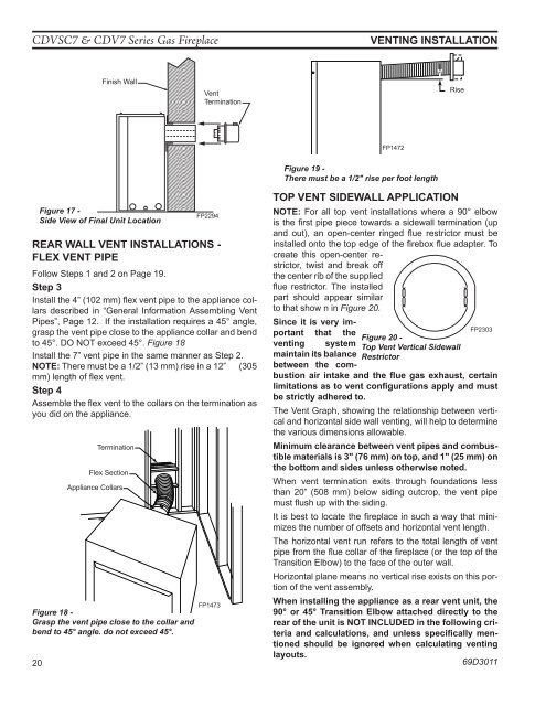
CDVSC7 & CDV7 Series <strong>Gas</strong> FireplaceVenting installationFinish WallVentTerminationRiseFP1472Figure 17 -Side View of Final Unit LocationFP2294FP2294Side View Vent Termination1/25/00 djtRear Wall Vent Installations -Flex Vent PipeFollow Steps 1 and 2 on Page 19.Step 3Install the 4” (102 mm) flex vent pipe to the appliance collarsdescribed in “General Inf<strong>or</strong>mation Assembling VentPipes”, Page 12. If the installation requires a 45° angle,grasp the vent pipe close to the appliance collar and bendto 45°. DO NOT exceed 45°. Figure 18Install the 7” vent pipe in the same manner as Step 2.NOTE: There must be a 1/2” (13 mm) rise in a 12” (305mm) length of flex vent.Step 4Assemble the flex vent to the collars on the termination asyou did on the appliance.TerminationFlex Section<strong>Appliance</strong> CollarsFigure 19 -There must be a 1/2" rise per foot lengthTop vent Sidewall ApplicationNOTE: F<strong>or</strong> all top vent installations where a 90° elbowis the first pipe piece towards a sidewall termination (upFP1472and out), an open-center ringed flue restrict<strong>or</strong> must berise in lengthinstalled onto the top edge 4/04 of the djt firebox flue adapter. Tocreate this open-center restrict<strong>or</strong>,twist and break offthe center rib of the suppliedflue restrict<strong>or</strong>. The installedpart should appear similarto that show n in Figure 20.Since it is very imp<strong>or</strong>tantthat theFP2303Figure 20 -venting system Top Vent Vertical Sidewallmaintain its balance Restrict<strong>or</strong>between the combustionair intake and the flue CDV7 gas rear exhaust, restrict<strong>or</strong> certainFP2303limitations as to vent configurations 3/09 apply and mustbe strictly adhered to.The Vent Graph, showing the relationship between verticaland h<strong>or</strong>izontal side wall venting, will help to determinethe various dimensions allowable.Minimum clearance between vent pipes and combustiblematerials is 3" (76 mm) on top, and 1" (25 mm) onthe bottom and sides unless otherwise noted.When vent termination exits through foundations lessthan 20” (508 mm) below siding outcrop, the vent pipemust flush up with the siding.It is best to locate the fireplace in such a way that minimizesthe number of offsets and h<strong>or</strong>izontal vent length.The h<strong>or</strong>izontal vent run refers to the total length of ventpipe from the flue collar of the fireplace (<strong>or</strong> the top of theTransition Elbow) to the face of the outer wall.H<strong>or</strong>izontal plane means no vertical rise exists on this p<strong>or</strong>tionof the vent assembly.When installing the appliance as a rear vent unit, theFP1473Figure 18 -90° <strong>or</strong> 45° Transition Elbow attached directly to theGrasp the vent pipe close to the collar andrear of the unit is NOT INCLUDED in the following criteriabend to 45° angle. do not exceed 45°.and calculations, and unless specifically men-tioned should be ign<strong>or</strong>ed when calculating venting20layouts.69D3011FP1473