Manual - Unvented Gas Log Heater or Vented Decorative Appliance
Manual - Unvented Gas Log Heater or Vented Decorative Appliance
Manual - Unvented Gas Log Heater or Vented Decorative Appliance

Create successful ePaper yourself
Turn your PDF publications into a flip-book with our unique Google optimized e-Paper software.
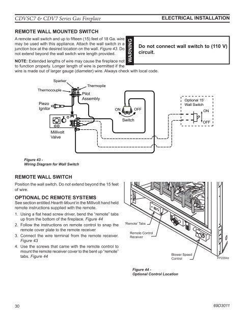
CDVSC7 & CDV7 Series <strong>Gas</strong> FireplaceElectrical installationRemote Wall mounted SwitchA remote wall switch and up to fifteen (15) feet of 18 Ga. wiremay be used with this appliance. Attach the wall switch in ajunction box at the desired location on the wall. Figure 43. Donot extend beyond the wall switch wire length provided.NOTE: Extended lengths of wire may cause the fireplace notto function properly. Longer length of wire is permitted if thewire is made out of larger gauge (diameter) wire. Always check with local code.WARNINGDo not connect wall switch to (110 V)circuit.ThermocouplePiezoIgnit<strong>or</strong>SparkerThermopilePilotAssemblyONOFFOptional 15’Wall SwitchONOFFPILOTONHILOSwitchOFFMillivoltValveFigure 43 -Wiring Diagram f<strong>or</strong> Wall SwitchRemote Wall SwitchPosition the wall switch. Do not extend beyond the 15 feetof wire.Optional DC Remote SystemsSee section entitled Hearth Mount in the Millivolt hand heldremote instructions supplied with the remote.1. Using a flat head screw driver, bend the “remote” FP2919 tabsup from the bottom of the fireplace. Figure 44 DV wiring diagram2. Follow the instructions on remote control to snap theremote cover plate to the remote receiver3. Connect the wire terminal from the remote receiver.Figure 434. Use the screws that came with the remote control tomount the remote receiver cover to the bent up “remote”tabs. Figure 44'Remote' TabsRemote ControlReceiverBlower SpeedControlFP2284aFigure 44 -Optional Control LocationFP2284aCDV7 controls30 69D3011