DFX, DBX Vent-Free Fireplace Systems - Unvented Gas Log Heater ...
DFX, DBX Vent-Free Fireplace Systems - Unvented Gas Log Heater ...
DFX, DBX Vent-Free Fireplace Systems - Unvented Gas Log Heater ...

Create successful ePaper yourself
Turn your PDF publications into a flip-book with our unique Google optimized e-Paper software.
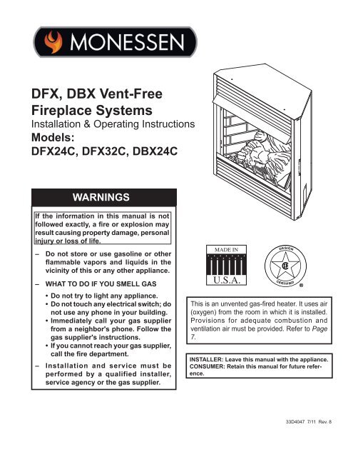
<strong>DFX</strong>, <strong>DBX</strong> <strong>Vent</strong>-<strong>Free</strong><br />
<strong>Fireplace</strong> <strong>Systems</strong><br />
Installation & Operating Instructions<br />
Models:<br />
<strong>DFX</strong>24C, <strong>DFX</strong>32C, <strong>DBX</strong>24C<br />
WARNINGS<br />
If the information in this manual is not<br />
followed exactly, a fire or explosion may<br />
result causing property damage, personal<br />
injury or loss of life.<br />
334051<br />
VFS <strong>DBX</strong> cover<br />
– Do not store or use gasoline or other<br />
flammable vapors and liquids in the<br />
vicinity of this or any other appliance.<br />
– WHAT TO DO IF YOU SMELL GAS<br />
• Do not try to light any appliance.<br />
• Do not touch any electrical switch; do<br />
not use any phone in your building.<br />
• Immediately call your gas supplier<br />
from a neighbor's phone. Follow the<br />
gas supplier's instructions.<br />
• If you cannot reach your gas supplier,<br />
call the fire department.<br />
– Installation and service must be<br />
performed by a qualified installer,<br />
service agency or the gas supplier.<br />
This is an unvented gas-fired heater. It uses air<br />
(oxygen) from the room in which it is installed.<br />
Provisions for adequate combustion and<br />
ventilation air must be provided. Refer to Page<br />
7.<br />
INSTALLER: Leave this manual with the appliance.<br />
CONSUMER: Retain this manual for future reference.<br />
33D4047 7/11 Rev. 8
<strong>DFX</strong> & <strong>DBX</strong> Series <strong>Vent</strong> <strong>Free</strong> <strong>Fireplace</strong>s<br />
CONTENTS<br />
Thank you and congratulations on your purchase of a<br />
Monessen <strong>Fireplace</strong>.<br />
PLEASE READ THE INSTALLATION AND OPERATION INSTRUCTIONS BEFORE USING THE APPLIANCE!<br />
IMPORTANT: Read all instructions and warnings carefully before starting installation.<br />
Failure to follow these instructions may result in a possible fire hazard and will void the warranty.<br />
<strong>DFX</strong>24C and <strong>DFX</strong>32C gas log appliances described in this manual feature the TRIPLE PLAY BURNER<br />
SYSTEM ® technology producing a full random yellow flame, full depth ember bed and glowing logs.<br />
Important Safety Information..................................... 3<br />
Code Approval.............................................................. 4<br />
Product Features......................................................... 5<br />
<strong>Gas</strong> Pressures.......................................................... 5<br />
<strong>Gas</strong> Specifications.................................................... 5<br />
Ignition Controls........................................................ 5<br />
Pilot........................................................................... 5<br />
Thermal Generator.................................................... 5<br />
<strong>Fireplace</strong> and Framing Dimensions.......................... 6<br />
Preinstallation Information.......................................... 7<br />
What You Will Need.................................................. 7<br />
General <strong>Fireplace</strong> Installation................................... 7<br />
Installation Information............................................... 8<br />
<strong>Fireplace</strong> Location..................................................... 8<br />
Clearances................................................................ 9<br />
<strong>Fireplace</strong> Installation............................................... 10<br />
Secure <strong>Heater</strong> to Floor or Hearth............................ 11<br />
Connect the <strong>Gas</strong>........................................................ 12<br />
Checking <strong>Gas</strong> Pressure............................................. 13<br />
Manual Control........................................................ 13<br />
Thermostat Control................................................. 13<br />
Millivolt Control........................................................ 13<br />
Electrical Wiring (Millivolt)........................................ 14<br />
Connect Optional Wall Switch................................. 14<br />
Connect Remote Receiver...................................... 15<br />
Check System Operation........................................ 15<br />
Final Installation......................................................... 16<br />
Screen Removal..................................................... 16<br />
Canopy Installation................................................. 16<br />
<strong>Log</strong> Placement........................................................ 17<br />
Rock Wool Placement............................................. 18<br />
Flame Appearance..................................................... 19<br />
Pilot Flame.............................................................. 19<br />
Burner Flame Appearance...................................... 20<br />
Operating Instructions............................................... 20<br />
For Your Safety Read Before Lighting.................... 21<br />
Thermostatic Control Lighting Instructions.............. 22<br />
Millivolt Control Lighting Instructions....................... 23<br />
Match Lighting Instructions..................................... 24<br />
Maintenance............................................................... 24<br />
Cleaning and Servicing........................................... 24<br />
Troubleshooting......................................................... 25<br />
Replacement Parts..................................................... 26<br />
Firebox.................................................................... 26<br />
<strong>DFX</strong>24C Millivolt & Manual Control Burner ............ 27<br />
<strong>DFX</strong>32C Millivolt Burner.......................................... 28<br />
<strong>DBX</strong>24C T-Stat Burner............................................ 29<br />
Optional Accessories................................................ 30<br />
Forced Air Kit.......................................................... 30<br />
Optional Brick.......................................................... 31<br />
Optional Trim........................................................... 31<br />
Trim Installation....................................................... 32<br />
Warranty...................................................................... 35<br />
<br />
33D4047
IMPORTANT SAFETY INFORMATION<br />
INSTALLER<br />
Please leave these instructions with the appliance.<br />
OWNER<br />
<strong>DFX</strong> & <strong>DBX</strong> Series <strong>Vent</strong> <strong>Free</strong> <strong>Fireplace</strong>s<br />
Please retain these instructions for future reference.<br />
WARNING<br />
• Any change to this heater or its controls can be dangerous.<br />
• Improper installation or use of the heater can cause serious injury or<br />
death from fire, burns, explosion or carbon monoxide poisoning.<br />
• Do not allow fans to blow directly into the fireplace. Avoid any drafts that<br />
alter burner flame patterns.<br />
• Do not use a blower insert, heat exchanger insert or other accessory,<br />
not approved for use with this heater where applicable.<br />
1. Due to high temperatures, the appliance should be<br />
located out of traffic and away from furniture and<br />
draperies.<br />
2. Children and adults should be alerted to the hazard<br />
of high surface temperature and should stay away<br />
to avoid burns or clothing ignition.<br />
3. Young children should be carefully supervised when<br />
they are in the same room with the appliance.<br />
4. Do not place clothing or other flammable material<br />
on or near the appliance.<br />
5. Any safety screen or guard removed for servicing<br />
an appliance, must be replaced prior to operating<br />
the heater.<br />
6. Installation and repair should be done by a qualified<br />
service person.<br />
7. To prevent malfunction and/or sooting, an unvented<br />
gas heater should be cleaned before use and at<br />
least annually by a professional service person.<br />
More frequent cleaning may be required due to<br />
excessive lint from carpeting, bedding materials,<br />
etc. It is imperative that control compartments,<br />
burners and circulating air passageways be kept<br />
clean.<br />
8. CARBON MONOXIDE POISONING: Early signs of<br />
carbon monoxide poisoning are similar to the flu with<br />
headaches, dizziness and/or nausea. If you have these<br />
signs, obtain fresh air immediately. Have the heater<br />
serviced as it may not be operating properly.<br />
9. The installation must conform with local codes or, in<br />
the absence of local codes, with the National Fuel<br />
<strong>Gas</strong> Code, ANSI Z223.l/NFPA54.<br />
10. Do not install the <strong>DFX</strong> model in a bathroom or bedroom.<br />
The <strong>DBX</strong> model may be installed in a bedroom, but<br />
not in a bathroom.<br />
11. Correct installation of the ceramic fiber logs, proper<br />
location of the heater, and annual cleaning are necessary<br />
to avoid potential problems with sooting. Sooting,<br />
resulting from improper installation or operation, can<br />
settle on surfaces outside the fireplace. Refer to log<br />
placement instructions for proper installation.<br />
33D4047<br />
12. Avoid any drafts that alter burner flame patterns. Do not<br />
allow fans to blow directly into fireplace. Do not place<br />
a blower inside burn area of firebox. Ceiling fans may<br />
create drafts that alter burner flame patterns. Sooting<br />
and improper burning will occur.<br />
13. Caution: Candles, incense, oil lamps, etc. produce<br />
combustion byproducts including soot. <strong>Vent</strong>-free appliances<br />
will not filter or clean soot produced by these<br />
types of products. In addition, the smoke and/or aromatics<br />
(scents) may be reburnt in the vent-free appliance<br />
which can produce odors. It is recommended to<br />
minimize the use of candles, incense, etc. while the<br />
vent-free appliance is in operation.<br />
14. This is an unvented gas-fired heater. It uses air<br />
(oxygen) from the room in which it is installed. Provisions<br />
for adequate combustion and ventilation air must<br />
be provided. Refer to Page 7.<br />
15. This heater shall not be installed in a room or space<br />
unless the required volume of indoor combustion air is<br />
provided by the method described in the National Fuel<br />
<strong>Gas</strong> Code, ANSI Z223.1/NFPA 54, the International<br />
Fuel <strong>Gas</strong> Code or applicable local codes.<br />
16. Keep room area clear and free from combustible<br />
materials, gasoline and other flammable vapors and<br />
liquids.<br />
17. <strong>Unvented</strong> gas heaters are a supplemental zone heater.<br />
They are not intended to be the primary heating appliance.<br />
18. <strong>Unvented</strong> gas heaters emit moisture into the living<br />
area. In most homes of average construction, this<br />
does not pose a problem. In houses of extremely<br />
tight construction, additional mechanical ventilation is<br />
recommended.<br />
19. During manufacturing, fabricating and shipping, various<br />
components of this appliance are treated with certain<br />
oils, films or bonding agents. These chemicals are not<br />
harmful but may produce annoying smoke and smells<br />
as they are burned off during the initial operation of the<br />
appliance; possibly causing headaches or eye or lung<br />
irritation. This is a normal and temporary occurrence.
<strong>DFX</strong> & <strong>DBX</strong> Series <strong>Vent</strong> <strong>Free</strong> <strong>Fireplace</strong>s<br />
The initial break-in operation should last two to three<br />
hours with the burner at the highest setting. Provide<br />
maximum ventilation by opening windows or doors to<br />
allow odors to dissipate. Any odors remaining after this<br />
initial break-in period will be slight and will disappear<br />
with continued use.<br />
20. Input ratings are shown in BTU per hour and are for<br />
elevations up to 2,000 feet. For elevations above 2,000<br />
feet, input ratings should be reduced 4 percent for each<br />
1,000 feet above sea level. Refer to the National Fuel<br />
<strong>Gas</strong> Code.<br />
21. The appliance and its appliance main gas valve must<br />
be disconnected from the gas supply piping system<br />
during any pressure testing of that system at test pressures<br />
in excess of 1/2 psig (3.5 kPa).<br />
22. The appliance must be isolated from gas supply piping<br />
system by closing its equipment shutoff valve during<br />
any pressure testing of the gas supply piping system<br />
at test pressures equal to or less than 1/2 psig (3.5<br />
kPa).<br />
23. Do not use this room heater if any part has been under<br />
water. Immediately call a qualified service technician<br />
to inspect the room heater and to replace any part of<br />
the control system and any gas control which has been<br />
under water.<br />
24. Never burn solid fuels in a fireplace where a unvented<br />
room heater is installed.<br />
25. Always have a fireplace screen in place when the<br />
appliance is in operation and, unless other provisions<br />
for combustion air are provided, the screen must have<br />
an opening(s) for induction of combustion air.<br />
IMPORTANT SAFETY INFORMATION<br />
This appliance may be installed in an<br />
aftermarket, permanently located,<br />
manufactured (mobile) home, where not<br />
prohibited by local codes.<br />
This appliance is only for use with the<br />
type of gas indicated on the rating<br />
plate. This appliance is not convertible<br />
for use with other gases.<br />
CODES<br />
Adhere to all local codes or, in their absence, the latest<br />
edition of THE NATIONAL FUEL GAS CODE ANSI Z223.1<br />
or NFPA54 which can be obtained from:<br />
American National Standards Institute, Inc.<br />
1430 Broadway<br />
New York, NY 10018<br />
or<br />
National Fire Protection Association, Inc.<br />
Batterymarch Park<br />
Quincy, MA 02269<br />
<br />
33D4047
PRODUCT FEATURES<br />
<strong>DFX</strong> & <strong>DBX</strong> Series <strong>Vent</strong> <strong>Free</strong> <strong>Fireplace</strong>s<br />
<strong>Fireplace</strong><br />
Screen<br />
<strong>Gas</strong> Specifications<br />
Input BTU/hr<br />
Model Fuel Control Max. Min.<br />
<strong>DFX</strong>24NVC Nat. Millivolt 22,000 17,000<br />
<strong>DFX</strong>24PVC LP Millivolt 22,000 17,000<br />
<strong>DFX</strong>32NVC Nat. Millivolt 26,000 0,000<br />
<strong>DFX</strong>32PVC LP Millivolt 26,000 0,000<br />
<strong>DBX</strong>24NTC Nat. T-Stat 10,000 --<br />
<strong>DBX</strong>24PTC LP T-Stat 10,000 --<br />
This vent-free fireplace must be mounted on the floor or<br />
on the optional fireplace hearth.<br />
operation<br />
Control Knobs<br />
Piezo Ignition<br />
On/Off Switch<br />
Figure 1 -<br />
<strong>Unvented</strong> <strong>Gas</strong> <strong>Heater</strong><br />
(Control Access Door Shown Open)<br />
FP2507<br />
VFS <strong>DBX</strong> controls<br />
FP2407<br />
This unvented gas heater requires no outside venting and<br />
burns cleanly with high heating efficiency.<br />
This zero-clearance unvented gas heater can be installed<br />
against (or recessed into) any wall that is accessible to a<br />
gas line.<br />
GAS pressures<br />
Control Fuel T-stat Millivolt<br />
Regulator Pressure Nat. 4.0” w.c. 3.5” w.c.<br />
Pilot Regulator Nat. n/a 3.5” w.c.<br />
Max. Inlet Pressure Nat. 10.5” w.c. 10.5” w.c.<br />
Min. Inlet Pressure Nat. 5.0” w.c. 5.0” w.c.<br />
Regulator Pressure LP 10.0” w.c. 10.0” w.c.<br />
Max. Inlet Pressure LP 13.0” w.c. 13.0” w.c.<br />
Min. Inlet Pressure LP 11.0” w.c. 11.0” w.c.<br />
NOTE: For LP models an external regulator is required<br />
to reduce supply pressure to a maximum of 13" w.c.<br />
ignition controls<br />
Piezo ignitor allows ignition of the pilot without the use of<br />
matches or batteries.<br />
Thermostat control has three (3) positions:<br />
OFF - All gas to the gas logs is shut off at the<br />
valve.<br />
IGN - Valve position to light/maintain a standing<br />
pilot.<br />
LOW/HI - Variable position corresponding to desired<br />
temperature.<br />
Pilot<br />
The gas log heater is fitted with a specially designed safety<br />
pilot light which senses the amount of oxygen available in<br />
the room and shuts the gas log heater off if the oxygen level<br />
begins to drop below a satisfactory level. The pilot can only<br />
be relit when adequate fresh air is available.<br />
Thermal Generator<br />
The millivolt gas log pilot is fitted with a millivolt generator<br />
to provide power for remote activation.<br />
33D4047
<strong>DFX</strong> & <strong>DBX</strong> Series <strong>Vent</strong> <strong>Free</strong> <strong>Fireplace</strong>s<br />
FIREPLACE and FRAMING DIMENSIONS<br />
S<br />
D<br />
L<br />
Min. Rough<br />
Opening<br />
Depth<br />
R<br />
H<br />
P<br />
S<br />
Q<br />
1/2”<br />
or 5/8”<br />
Min. Rough<br />
Opening<br />
Height<br />
M<br />
O - Min. Rough Opening Width<br />
J<br />
G<br />
N<br />
B<br />
E<br />
C<br />
Figure 2 -<br />
<strong>Fireplace</strong> and Framing Dimensions<br />
I<br />
F<br />
A<br />
K<br />
Ref. <strong>DFX</strong>24C/<strong>DBX</strong>24C <strong>DFX</strong>32C<br />
A 4Z\x" (622 mm) 32" (813 mm)<br />
B Z\x" (572 mm) 28C\v" (730 mm)<br />
C<br />
D<br />
6Z\x"<br />
14"<br />
334051 (673 mm)<br />
VFS (356 <strong>DBX</strong> mm) dims<br />
30"<br />
21C\v"<br />
(762 mm)<br />
(553 mm)<br />
E 17" (432 mm) 20Z\v" (514 mm)<br />
F 4B\," (118 mm) 4C\v" (121 mm)<br />
G 4M\," (124 mm) 5" (127 mm)<br />
H 11M\," (302 mm) 13C\," (340 mm)<br />
I 1" (25 mm) 1B\," (41 mm)<br />
J 10Z\x" (267 mm) 12" (305 mm)<br />
K 9" (229 mm) 10B\," (270 mm)<br />
L 13Z\," (333 mm) 17Z\x" (445 mm)<br />
M 1" (533 mm) 27" (686 mm)<br />
Framing Dimensions<br />
N 6C\v" (680 mm) 30Z\v" (768 mm)<br />
O 4C\v" (629 mm) 32Z\x" (826 mm)<br />
P 10Z\x" (267 mm) 12Z\v" (311 mm)<br />
Q 42Z\x" (1080 mm) 53C\v" (1326 mm)<br />
R 1" (533 mm) 26C\v" (680 mm)<br />
S 30" (762 mm) 38" (965 mm)<br />
<br />
33D4047
Preinstallation information<br />
WARNING<br />
• Handle the gas log burner assembly by<br />
the grate only. Do not pick the unit up by<br />
the burners.<br />
• Gloves are recommended when handling<br />
ceramic fiber logs to prevent skin irritation<br />
from loose fibers. <strong>Log</strong>s are fragile —<br />
handle with care.<br />
GETTING STARTED<br />
Make sure you have received all parts:<br />
Check your packing list to verify that all listed parts have<br />
been received. You should have the following:<br />
• <strong>Unvented</strong> gas heater • Trim kit<br />
• Two (2) 90°-angle brackets • Ceramic fiber logs<br />
• Installation/operating instructions<br />
• Canopy and three (3) screws<br />
• Two (2) anchoring screws • Four (4) black screws<br />
Millivolt controlled heater designed to be operated with<br />
optional devices for ON/OFF functions.<br />
• Hand held Remote with receiver<br />
• Wall T-stat with 20' wire<br />
• Wall switch with 20' wire<br />
• Hand held Thermostat Remote w/receiver<br />
Carefully inspect the contents for shipping damage. If any<br />
parts are missing or damaged, immediately inform the<br />
dealer from whom you purchased the appliance. Do not<br />
attempt to install any part of the appliance unless you<br />
have all parts in good condition.<br />
What you will need for installation:<br />
You must have the following items available before proceeding<br />
with installation:<br />
• External regulator (for propane/LPG only)<br />
• Manual shutoff valve<br />
• Piping which complies with local codes<br />
• Sediment trap<br />
• Phillips head screwdriver<br />
• Tee joint.<br />
• Pipe sealant approved for use with propane/LPG<br />
• Pipe wrench<br />
(Resistant to sulfur compounds)<br />
WARNING<br />
<strong>DFX</strong> & <strong>DBX</strong> Series <strong>Vent</strong> <strong>Free</strong> <strong>Fireplace</strong>s<br />
In planning the installation for the fireplace it is necessary<br />
to determine where the unit is to be installed and whether<br />
optional accessories are desired. <strong>Gas</strong> supply piping should<br />
also be planned. The following steps represent the normal<br />
sequence of installation. Each installation is unique, however,<br />
and might require a different sequence.<br />
1. Position fireplace in desired location. Refer to the Location<br />
of <strong>Fireplace</strong> and Clearances and Height Requirements,<br />
and Firebox Framing sections found in this<br />
manual.<br />
Note: Be sure all packing material has been removed<br />
from underside the unit.<br />
2. Install canopy and logs per instructions found in this<br />
manual. The canopy MUST be installed for safe operation<br />
of the unit.<br />
3. Field wire main power supply to units with fan kit. Refer<br />
to the Electrical Section found in this manual. (Electrical<br />
connections should only be performed by an experienced,<br />
licensed certified tradesman).<br />
4. Install optional ON/OFF kit on units with millivolt control.<br />
Refer to the installation instructions included with the<br />
kit and also refer to the Electrical Wiring section found<br />
in this manual.<br />
5. Plumb gas line. Refer to the Connecting the <strong>Gas</strong> section<br />
found in this<br />
manual. (<strong>Gas</strong> connections should only be performed<br />
by an experienced,<br />
licensed/certified tradesman).<br />
6. Complete finish wall material and/or surround.<br />
WARNING<br />
Do not install the heater:<br />
• Where curtains, furniture, clothing, or<br />
other flammable objects are less than<br />
42" from the front of the heater.<br />
• In high traffic areas.<br />
• In windy or drafty areas.<br />
If the area in which the heater may be<br />
operated does not meet the required volume<br />
for indoor combustion air, combustion and<br />
ventilation air shall be provided by one<br />
of the methods described in the National<br />
Fuel <strong>Gas</strong> Code, ANSI Z223.1/NFPA 54, the<br />
International Fuel <strong>Gas</strong> Code or applicable<br />
local codes.<br />
33D4047
<strong>DFX</strong> & <strong>DBX</strong> Series <strong>Vent</strong> <strong>Free</strong> <strong>Fireplace</strong>s<br />
FIREPLACE INSTALLATION<br />
<strong>Fireplace</strong> Location<br />
Carefully select the best location for installation of your unvented fireplace. The following factors<br />
should be taken into consideration.<br />
• Clearance to side wall, ceiling, woodwork and window or other combustibles. Refer to “Clearances”<br />
section on Page 10. Minimum clearances to combustibles must be maintained.<br />
• Location must not be affected by drafts caused by kitchen exhaust fans, ceiling fans, return<br />
air registers for forced air furnaces / air conditioners, windows or doors.<br />
• Installation must provide adequate ventilation and combustion air.<br />
• DO NOT INSTALL THESE MODELS IN A BEDROOM OR BATHROOM. Exception: The<br />
<strong>DBX</strong> may be installed in a bedroom, but not in a bathroom.<br />
• Location should be out of high traffic areas and away from furniture and draperies due to<br />
heat from firebox.<br />
• Never obstruct the front opening of the unvented fireplace or restrict the flow of combustion<br />
and ventilation air.<br />
• Minimize modifications to existing construction. Refer to Figure 3 below for location suggestions.<br />
• Do not install in the vicinity where gasoline or other flammable liquids may be stored. The<br />
unvented firebox must be kept clear and free from the combustible materials.<br />
Figure 3 -<br />
Possible <strong>Fireplace</strong> Locations<br />
FP2440<br />
FP2440<br />
fireplace locations<br />
<br />
33D4047
FIREPLACE INSTALLATION<br />
<strong>DFX</strong> & <strong>DBX</strong> Series <strong>Vent</strong> <strong>Free</strong> <strong>Fireplace</strong>s<br />
Ensure that minimum clearances shown in Figures 5 and 6 are maintained. Left and right clearances<br />
are determined when facing the front of the firebox.<br />
Follow these instructions carefully to ensure safe installation. Failure to follow these requirements<br />
may create a fire hazard.<br />
Sidewall Clearances — The clearance from the inside of the appliance to any combustible adjacent<br />
wall should not be less than 9" for the <strong>DBX</strong>24C/<strong>DFX</strong>24C and <strong>DFX</strong>32C. Figure 4<br />
Ceiling Clearance — The ceiling must be at least 42" from the top of the firebox opening. Figure 4<br />
Back Wall Clearance — The appliance may be placed against a combustible back wall.<br />
Floor Clearance — The fireplace may be installed directly on a combustible floor or a raised platform<br />
of an appropriate height. Do not place fireplace on carpeting, vinyl, tile or other soft floor coverings. It<br />
may, however, be placed on flat wood, plywood, particle board or other hard surfaces. Be sure fireplace<br />
rests on a solid continuous floor or platform with appropriate framing for support and so that no cold<br />
air can enter from under the firebox.<br />
Mantel clearances — The canopy supplied with the unit must be installed. If a combustible mantel<br />
is installed. It must meet the clearance requirements detailed in Figure 5.<br />
NOTE: The MHSC Barrington Cabinet Mantel Model series BWC300, BWC400 and BWC500 are<br />
specially designed to comply with all mantel temperature requirements. Any custom-built mantel must<br />
comply with all clearance requirements shown in this instruction manual.<br />
12”<br />
42" Minimum<br />
19”<br />
9"<br />
Minimum<br />
9"<br />
Minimum<br />
2”<br />
10”<br />
Figure 4 -<br />
Sidewall and Ceiling Clearances<br />
FP2441<br />
sidewall clg clear<br />
FP2441<br />
FP2508<br />
Figure 5 -<br />
Mantel Clearances<br />
Canopy<br />
WARNING<br />
The dimensions shown in Figures 4 and 5 are minimum clearances to<br />
maintain in installing this heater. Left and right clearances are determined<br />
when facing the front of the heater.<br />
Follow these instructions carefully to ensure safe installation. Failure FP2508 to<br />
follow instructions exactly can create a fire hazard.<br />
VFS <strong>DBX</strong> mantel clearances<br />
33D4047
<strong>DFX</strong> & <strong>DBX</strong> Series <strong>Vent</strong> <strong>Free</strong> <strong>Fireplace</strong>s<br />
FIREPLACE INSTALLATION<br />
If unit is to be “built in”, fireplace framing can be built before<br />
or after the appliance is set in place. BE SURE THAT ALL<br />
PACKING MATERIAL HAS BEEN REMOVED FROM THE<br />
UNDERSIDE OF THE UNIT PRIOR TO SETTING THE<br />
FIREBOX IN PLACE. Construct fireplace framing following<br />
Figure 2 on Page 6 for fireplace dimensions. The framing<br />
headers may rest directly on top of the firebox.<br />
The fireplace may be installed directly on a combustible<br />
floor or a raised platform of an appropriate height. Do<br />
not place fireplace on carpeting, vinyl, tile or other soft<br />
floor coverings. It may, however, be placed on flat wood,<br />
plywood, particle board or other hard surfaces. Be sure<br />
fireplace rests on a solid continuous floor or platform with<br />
appropriate framing for support and so that no cold air can<br />
enter from under the firebox.<br />
Anchor fireplace to the side framing members using nailing<br />
flanges.<br />
WARNING<br />
The fireplace must be installed giving full<br />
consideration to the clearance and height<br />
requirements identified in this manual.<br />
K<br />
Ref. FP2445 <strong>DFX</strong>24C <strong>DBX</strong>24C <strong>DFX</strong>32C<br />
J opening 26C\v" size 26C\v" 31Z\v"<br />
(680 mm) (680 mm) (800 mm)<br />
K 25" 5" 32ZC\zn"<br />
(635 mm) (635 mm) (833 mm)<br />
Figure 6 -<br />
Custom Cabinet<br />
J<br />
FP2445<br />
When finishing a custom cabinet, mantel or other built-in<br />
enclosure, the opening size to accommodate the fireplace with<br />
trim installed is as follows:<br />
1. Bend out the nailing flanges located on each side of the<br />
firebox.<br />
2. Slide the firebox into prepared framing or position firebox<br />
in its final position and frame later.<br />
3. Level the firebox by checking the top edge of the firebox.<br />
Shim if necessary.<br />
4. Anchor firebox to the side framing members using 8d<br />
nails or other suitable fasteners. Figure 7<br />
5. The canopy must be installed for safe operation of<br />
the heater. Refer to Page 16 for canopy installation<br />
details.<br />
Nail Sides<br />
Through Nailing<br />
Flanges<br />
FP2509<br />
Figure 7 -<br />
Nailing Flanges<br />
FP2509<br />
nailing flanges<br />
10 33D4047
FIREPLACE INSTALLATION<br />
<strong>DFX</strong> & <strong>DBX</strong> Series <strong>Vent</strong> <strong>Free</strong> <strong>Fireplace</strong>s<br />
SECURING HEATER TO FLOOR OR HEARTH<br />
Note: Clearance requirements as detailed in “Clearances and Height Requirements”<br />
section on Page 15 of this manual, must be met before securing the heater in place.<br />
To prevent movement, the heater must be secured to the floor or hearth.<br />
1. Open the control access door and remove the screen.<br />
2. Remove carton containing the four-log set.<br />
3. To remove the grate and base assembly, take out two (2) screws as shown in Figure 8.<br />
4. Lift grate and base assembly out of the firebox.<br />
5. Secure the firebox with two anchoring screws (3/16" x 1Z\v" length) supplied with the fireplace<br />
system. Figure 9<br />
Note: If the unit is mounted on carpeting, tile or combustible material without the hearth, a metal<br />
or wooden base covering the entire width and depth of the base must be installed.<br />
Screws<br />
Grate<br />
Figure 8 -<br />
Remove Grate<br />
FP2515<br />
Anchor Screws<br />
3/16" x 1Z\v"<br />
Figure 9 -<br />
Secure <strong>Heater</strong> to Floor or Hearth<br />
FP2516<br />
FP2515<br />
remove grate<br />
FP2516<br />
secure base<br />
33D4047 11
<strong>DFX</strong> & <strong>DBX</strong> Series <strong>Vent</strong> <strong>Free</strong> <strong>Fireplace</strong>s<br />
FIREPLACE INSTALLATION<br />
NOTICE: A qualified gas appliance installer must connect the heater to the gas supply.<br />
Consult all local codes.<br />
WARNING<br />
Use new black iron or steel pipe. Internally tinned copper or copper<br />
tubing can be used per National Fuel Code, section 2.6.3, providing gas<br />
meets hydrogen sulfide limits, and where permitted by local codes. <strong>Gas</strong><br />
piping system must be sized to provide minimum inlet pressure (Listed<br />
on Data Plate) at the maximum flow rate (BTU/hr). Undue pressure loss<br />
will occur if the pipe is too small.<br />
A manual shutoff valve must be installed upstream of the appliance.<br />
Union tee and plugged 1/8" NPT pressure tapping point should be<br />
installed upstream of the appliance. Figure 9<br />
A sediment trap should be installed upstream to prevent moisture and<br />
contaminants from passing through the pipe to appliance controls and<br />
burners. Failure to do so could prevent the appliance from operating<br />
reliable. Figure 10<br />
To <strong>Fireplace</strong><br />
Pipe Coupling<br />
Stainless<br />
Flexible Tube<br />
Pipe<br />
Locations Pressure Tapping<br />
Point Installation<br />
<strong>Gas</strong> Supply<br />
Inlet<br />
Figure 10 -<br />
<strong>Gas</strong> Connection<br />
Manual Shutoff<br />
Valve<br />
Sediment<br />
Trap<br />
Tee Joint<br />
Pipe Nipple<br />
3” Min.<br />
Cap<br />
FP2447<br />
IMPORTANT: Loosen the pipe adapter on the flex tube before installing to the system<br />
piping.<br />
Always use an external regulator for all propane/LPG heaters only, to reduce the supply<br />
tank pressure to a maximum of 13" w.c. This is in addition to the internal regulator in the<br />
heater valve.<br />
WARNING<br />
FP2447<br />
gas connection<br />
Check gas type: The gas supply must be the same as stated on the<br />
heater’s rating plate. If the gas supply is different, DO NOT INSTALL<br />
THE HEATER. Contact your dealer for the correct model.<br />
12 33D4047
FIREPLACE INSTALLATION<br />
<strong>DFX</strong> & <strong>DBX</strong> Series <strong>Vent</strong> <strong>Free</strong> <strong>Fireplace</strong>s<br />
When tightening the joint to the valve, hold the valve securely to prevent movement.<br />
Test all gas joints from the gas meter to the heater valve for leaks using a gas analyzer or soap<br />
and water solution after completing connection. DO NOT USE AN OPEN FLAME.<br />
Check the gas pressure with the appliance burning and the control set to HIGH.<br />
Open control access door at bottom front of unit to find valve and regulator referred to below.<br />
WARNING<br />
Do not use open flame to check for gas<br />
leaks.<br />
WARNING<br />
Connecting directly to an unregulated<br />
propane/LP tank can cause an<br />
explosion.<br />
Manual Control<br />
Figure 11<br />
The pressure regulator is preset and locked to discourage<br />
tampering. If the pressure is not as specified, replace the<br />
regulator with the correct part from the parts list in this<br />
manual.<br />
Remove 1/8" NPT plug, located on side of regulator body.<br />
Install fitting and tubing to pressure gauge. After taking<br />
pressure reading, reinstall test plug. Check for gas leaks.<br />
FP2510<br />
Test Points<br />
Figure 12 -<br />
Alternate Test Point Location for<br />
Thermostat control Units<br />
FP2510<br />
thermostat control<br />
NPT Test Plug<br />
Figure 11 -<br />
Pressure Test Point Location<br />
- Manual Control<br />
FP2499<br />
FP2499<br />
manual valve<br />
Thermostat Control<br />
Figure 12<br />
Turn captured screw counter clockwise two or three turns<br />
and then place tubing to pressure gauge over test point<br />
(Use test point closest to control knob). After taking pressure<br />
reading, be sure and turn captured screw clockwise<br />
firmly to reseal. Do not over torque. Check for gas leaks.<br />
Millivolt Control<br />
Figure 13<br />
The valve regulator controls the burner pressure which<br />
should be checked at the pressure test point.<br />
Test Port<br />
'A'<br />
Figure 13 -<br />
Pressure Test Point Location - Millivolt Valve<br />
FP2511<br />
Turn captured screw counter clockwise two or three turns<br />
and then place tubing to pressure gauge over test point.<br />
(Use test point “A” closest to gas inlet). After taking pressure<br />
reading, FP2511 be sure and turn captured screw clockwise firmly<br />
to reseal. millivolt Do test not point over torque. Check for gas leaks.<br />
33D4047 13
<strong>DFX</strong> & <strong>DBX</strong> Series <strong>Vent</strong> <strong>Free</strong> <strong>Fireplace</strong>s<br />
ELECTRICAL INSTALLATION<br />
ODS Pilot<br />
On/Off<br />
Switch<br />
Field Installed Optional<br />
Wall Switch or<br />
Remote Receiver<br />
ODS<br />
Pilot<br />
Valve<br />
On/Off<br />
Switch<br />
TH = 3<br />
TP = 1<br />
TP/TH = 2<br />
Spade<br />
Terminal<br />
Figure 14 -<br />
Wiring Diagram<br />
Switch<br />
FP2112a<br />
WARNING<br />
Label all wires prior to disconnection when<br />
servicing controls. Wiring errors can cause<br />
improper and dangerous operation. Verify<br />
proper operation after servicing.<br />
FP2112a<br />
wiring diagram<br />
8/09<br />
Connecting Optional Wall Switch<br />
1. Use 18 awg, two-wire cable, 15 feet maximum length.<br />
2. At one end of the cable, connect both wires to the wall switch or thermostat. At the other end,<br />
connect one wire to TP/TH and one wire to TH. The color of the wires does not matter.<br />
14 33D4047
ELECTRICAL INSTALLATION<br />
<strong>DFX</strong> & <strong>DBX</strong> Series <strong>Vent</strong> <strong>Free</strong> <strong>Fireplace</strong>s<br />
Connect Remote Receiver<br />
THESE INSTRUCTIONS SUPERCEDE THE SECTION<br />
ENTITLED “HEARTH MOUNT” IN THE Millivolt<br />
HAND-HELD REMOTE INSTRUCTIONS SUPPLIED<br />
WITH THE REMOTE.<br />
Figure 15<br />
1. Remove bottom louvre door.<br />
2. Connect the remote connectors located in the unit.<br />
3. Stick Velcro• pads with self-adhesive backing to bottom<br />
of remote receiver and to floor of compartment behind<br />
access panel.<br />
4. Attach remote receiver to firebox with Velcro• pads.<br />
Control switch must face forward.<br />
NOTE: Do not place remote in combustion chamber.<br />
Velcro•<br />
Remote<br />
Receiver<br />
SKYTECH<br />
OFF REMOTE ON<br />
Figure 15 -<br />
Install Remote Receiver<br />
FIREPLACE<br />
REMOTE<br />
Velcro•<br />
FP2512<br />
Check System Operation<br />
The millivolt system and individual components may be checked with a millivolt meter having<br />
a 0-1000 mV range. Conduct each check shown in chart below by connection meter test leads<br />
to terminals as indicated.<br />
A. Complete MilliVolt System Check<br />
(“A” Reading - Thermostat contacts CLOSED - Control Knob “ON” - Main burner<br />
should turn ON)<br />
a. If the reading is more than 100 millivolts and the automatic valve still does not come on,<br />
replace the control.<br />
b. If the closed circuit reading (“A” reading) is less than 100 millivolts, determine cause for<br />
low reading, proceed to Section B below.<br />
B. Thermopile Output Reading Check<br />
(“B” Reading - Thermostat contacts OPEN - Main burner OFF)<br />
1. Check gas pressure to the unit. If gas pressure is within minimum and maximum on data<br />
plate, then check pilot voltage, 325 millivolts minimum. If the minimum millivolt reading is<br />
not obtainable, replace pilot.<br />
FP2512<br />
install remote rcvr<br />
Connect Meter Switch or Meter<br />
Check To Leads to Thermostat Reading<br />
Test Test Terminals Contacts Should Be<br />
A Complete 2 & 3 Closed Closed<br />
System<br />
B Thermopile 1 & 2 Open Open<br />
33D4047 15
<strong>DFX</strong> & <strong>DBX</strong> Series <strong>Vent</strong> <strong>Free</strong> <strong>Fireplace</strong>s<br />
FINAL INSTALLATION<br />
WARNING<br />
Do not operate the unit without the screen<br />
frame panel and canopy installed.<br />
Canopy<br />
REMOVE SCREEN<br />
Figure 16<br />
1. Remove bottom louver.<br />
2. Removing fireplace screen frame panel by pushing<br />
screen frame panel up and out.<br />
NOTE: <strong>Fireplace</strong> screen must be removed to access log<br />
box and to install canopy.<br />
<strong>Fireplace</strong><br />
Screen<br />
Louvre<br />
Figure 16 -<br />
Remove <strong>Fireplace</strong> Screen Panel<br />
FP2513<br />
INSTALL CANOPY<br />
Figure 17<br />
1. Push louvers up and out to remove top louver assembly.<br />
2. Align the black canopy with the holes in the top frame<br />
assembly.<br />
3. Install the three (3) screws (in owner’s manual packaging)<br />
which attach the canopy to the top frame assembly.<br />
4. Tighten all screws. Make sure the canopy is level and<br />
secure. Install top louver assembly.<br />
Figure 17 -<br />
Install Canopy<br />
FP2513<br />
Screws<br />
remove screen<br />
Canopy<br />
FP2514<br />
FP2514<br />
install canopy<br />
16 33D4047
LOG PLACEMENT<br />
<strong>DFX</strong> & <strong>DBX</strong> Series <strong>Vent</strong> <strong>Free</strong> <strong>Fireplace</strong>s<br />
Before you begin — This unit is supplied with six (6) ceramic fiber logs. Do not handle<br />
these logs with your bare hands. Always wear gloves to prevent skin irritation from<br />
ceramic fibers. After handling the logs, wash your hands gently with soap and water to<br />
remove any traces of fibers.<br />
WARNING<br />
CAUTION<br />
The positioning of the logs is critical to the safe and clean operation of<br />
this heater. Sooting and other problems may result if the logs are not<br />
properly and firmly positioned in the appliance. Never add additional<br />
logs or embellishments such as pine cones, vermiculite or rock wool<br />
to the heater. Only use the logs and TPB-RW (rock wool) supplied with<br />
the unit.<br />
Failure to position the parts in accordance with diagrams below or<br />
to use only parts specifically approved for this heater may result in<br />
property damage or personal injury.<br />
DO NOT sprinkle volcanic rock on the logs or around the pilot or the<br />
main burner. This may cause sooting. Only place volcanic rock on the<br />
floor of the fireplace.<br />
During initial operation of the new heater, burning logs will give off a<br />
paper burning smell and orange flames will be present. Simply open<br />
the windows for a few hours to vent the odor.<br />
<strong>DFX</strong>24C log placement<br />
Figure 18<br />
1. Install the rear log (#3) on back of burner.<br />
2. Install the right log (#1) on burner pins on right side of<br />
burner.<br />
3. Install the left log (#2) on burner pins on left side of<br />
burner.<br />
Left <strong>Log</strong><br />
#2<br />
Right <strong>Log</strong> #1<br />
Rear <strong>Log</strong> #3<br />
Burner<br />
Pins<br />
Burner<br />
Pins<br />
Figure 18 -<br />
<strong>DFX</strong>24C <strong>Log</strong> Placement<br />
LG699<br />
33D4047 17<br />
LG699<br />
24VFSC logs
<strong>DFX</strong> & <strong>DBX</strong> Series <strong>Vent</strong> <strong>Free</strong> <strong>Fireplace</strong>s<br />
<strong>DFX</strong>32C <strong>Log</strong> placement<br />
Figure 19<br />
1. Install front right log (#1) on two pins on right side of<br />
burner.<br />
2. Install left front log (#2) on two pins on left side of<br />
burner.<br />
3. Install back log (#3) on back of burner.<br />
4. Install right middle log (#4) on two pins on burner. Rest<br />
right end of right middle log on the right front log.<br />
5. Install left middle log (#5) on two pins on burner. Rest<br />
left end of left middle log on left front log.<br />
Left Middle<br />
<strong>Log</strong> #5<br />
Left Front<br />
<strong>Log</strong> #2<br />
Rear <strong>Log</strong><br />
#3<br />
LOG PLACEMENT<br />
Right<br />
Middle<br />
<strong>Log</strong> #4<br />
Right Front<br />
<strong>Log</strong> #1<br />
Pins<br />
Figure 19 -<br />
<strong>DFX</strong>32C <strong>Log</strong> Placement<br />
Pins<br />
Pins<br />
<strong>DBX</strong>24C <strong>Log</strong> placement<br />
Install one-piece log on two burner pins. Figure 20<br />
One-piece <strong>Log</strong><br />
PlacE rock wool<br />
Pins<br />
LG700<br />
<strong>DFX</strong>24C and <strong>DFX</strong>32C models<br />
LG700<br />
After installing logs, pull apart dime-size pieces of rock<br />
32VFSC logs<br />
wool. Sprinkle rock wool evenly over burner ports. Wash<br />
hands after installing rock wool.<br />
Itching may occur.<br />
Burner<br />
Pin<br />
Dime Sized<br />
Rockwool<br />
Pieces<br />
Figure 21 -<br />
Place Rockwool <strong>DFX</strong>24C/<strong>DFX</strong>32C<br />
Figure 20 -<br />
24BDXC <strong>Log</strong> Placement<br />
Burner Pin<br />
LG701<br />
WARNING<br />
• Use only rock wool provided with log<br />
set.<br />
• Do not add additional rock wool.<br />
LG702<br />
VFS <strong>DBX</strong> rockwool<br />
• Place rock wool on burner ports only.<br />
• Keep air gap between rear log and<br />
burner clean.<br />
18 33D4047<br />
LG701<br />
24BDXC logs
FLAME APPEARANCE<br />
<strong>DFX</strong> & <strong>DBX</strong> Series <strong>Vent</strong> <strong>Free</strong> <strong>Fireplace</strong>s<br />
Flames from the pilot, front and rear burner should be visually checked as soon as the<br />
heater is installed. In addition, periodically check the flames visually during operation.<br />
Check the pilot flame<br />
The pilot flame must always be present when the heater is in operation. It should just<br />
touch the top of the thermocouple tip for natural. Refer to Figures 22 & 23 for correct pilot<br />
flame.<br />
If the pilot flame does not touch the thermocouple, then the main burner cannot function<br />
reliably. Refer to Figures 22 & 23 for incorrect shape of pilot flame.<br />
Millivolt Control<br />
Thermocouple<br />
for Natural <strong>Gas</strong><br />
Thermocouple<br />
for Natural <strong>Gas</strong><br />
Thermocouple<br />
for LP<br />
FP2272<br />
Thermocouple<br />
for LP<br />
FP2273<br />
Correct Pilot Flame Appearance<br />
Incorrect Pilot Flame Appearance<br />
Figure 22 -<br />
Millivolt Control Pilot Flame Appearance<br />
HI/LO CONTROL<br />
Thermocouple<br />
for Natural <strong>Gas</strong><br />
FP2272<br />
pilot correct flame<br />
Thermocouple<br />
for LP<br />
Thermocouple<br />
for Natural <strong>Gas</strong><br />
FP2273<br />
pilot bad flame<br />
Thermocouple<br />
for LP<br />
FP2502<br />
Correct Pilot Flame Appearance<br />
Incorrect Pilot Flame Appearance<br />
Figure 23 -<br />
Hi/Lo Control Pilot Flame Appearance<br />
FP2501<br />
manual pilot flame<br />
33D4047 19
<strong>DFX</strong> & <strong>DBX</strong> Series <strong>Vent</strong> <strong>Free</strong> <strong>Fireplace</strong>s<br />
FLAME APPEARANCE<br />
Checking burner flame<br />
<strong>DFX</strong>24C and <strong>DFX</strong>32C models<br />
In normal operation at full rate after 15 minutes, the following<br />
flame appearances should be observed:<br />
Burner will have a random pattern of yellow flames. Figures<br />
24 and 25. There should be glowing embers in front<br />
of burner.<br />
<strong>DBX</strong>24C model<br />
In normal operation at full rate after 15 minutes, the following<br />
flame appearances should be observed:<br />
The flames inside the one-piece log may be yellow. The<br />
flames should extend approximately 2" - 4" above the log.<br />
Figure 26<br />
NOTE: The front flames and embers will be an opaque<br />
orange color during the burn off time.<br />
Figure 24 -<br />
<strong>DFX</strong>24C <strong>Log</strong> Flame Appearance<br />
LG703<br />
LG703<br />
24VFSC log flames<br />
2” - 4”<br />
Figure 25 -<br />
<strong>DFX</strong>32C <strong>Log</strong> Flame Appearance<br />
OPERATING INSTRUCTIONS<br />
LG704<br />
32VFSC log flames<br />
LG704<br />
Figure 26 -<br />
<strong>DBX</strong>24C <strong>Log</strong> Flame Appearance<br />
Avoid any drafts that alter burner flame patterns. Do not allow fans to blow directly into<br />
the fireplace. Do not place a blower inside the burn area of the firebox. Ceiling fans may<br />
create drafts that alter flame patterns. Sooting and improper burning will result.<br />
During manufacturing, fabricating and shipping, various components of this appliance are<br />
treated with certain oils, films or bonding agents. These chemicals are not harmful, but may<br />
produce annoying smoke and smells as they are burned off during the initial operation of<br />
the appliance, possibly causing headaches or eye or lung irritation. This is a normal and<br />
temporary occurrence.<br />
The initial break-in operation should last two to three hours with the burner at the highest<br />
setting. Provide maximum ventilation by opening windows or doors to allow odors to dissipate.<br />
Any odors remaining after this initial break-in will be slight and will disappear with<br />
continued use.<br />
This appliance must not be used with glass doors in the closed position. This can lead to<br />
pilot outages and severe sooting outside the fireplace.<br />
LG705<br />
24<strong>DBX</strong>C log flames<br />
20 33D4047<br />
LG705
OPERATING INSTRUCTIONS<br />
<strong>DFX</strong> & <strong>DBX</strong> Series <strong>Vent</strong> <strong>Free</strong> <strong>Fireplace</strong>s<br />
for your safety read before lightinG<br />
WARNING<br />
If you do not follow these instruction<br />
exactly, a fire or explosion may result<br />
causing property damage, personal injury<br />
or loss of life.<br />
A. This appliance is equipped with a piezo ignition device which automatically lights the pilot. If piezo<br />
is not working properly, refer to Match Lighting Instructions, Page 24.<br />
B. BEFORE OPERATING smell all around the appliance area for gas. Be sure to smell next to the floor<br />
because some gas is heavier than air and will settle on the floor.<br />
WHAT TO DO IF YOU SMELL GAS:<br />
• Do not attempt to light any appliance.<br />
• Do not touch any electric switch; do not use any phone in your building.<br />
• Immediately call your gas supplier from a neighbor's phone. Follow the gas supplier's instructions.<br />
• If you cannot reach your gas supplier, call the fire department.<br />
C. Use only your hand to push in, or turn the gas control knob. Never use tools. If the knob will not<br />
push in or turn by hand, don't try to repair it. Call a qualified service technician. Force or attempted<br />
repair may result in a fire or explosion.<br />
D. Do not use this appliance if any part of it has been under water. Immediately call a qualified service<br />
technician to inspect the appliance and to replace any part of the control system and any gas control<br />
that has been under water.<br />
Control Knobs<br />
Piezo Ignitor<br />
<strong>DFX</strong>C/<strong>DBX</strong>C Controls<br />
On/Off Switch<br />
FP2407<br />
FP2507<br />
VFS <strong>DBX</strong> controls<br />
33D4047 21
<strong>DFX</strong> & <strong>DBX</strong> Series <strong>Vent</strong> <strong>Free</strong> <strong>Fireplace</strong>s<br />
OPERATING INSTRUCTIONS<br />
thermostatIC control lighting instructions<br />
1. STOP! Read the safety information .<br />
2. Make sure the manual shutoff valve is fully open.<br />
3. This heater is equipped with an ignition device (piezo) which automatically lights the pilot.<br />
4. Refer to Page 21 for the location of the piezo ignitor and control knob. Turn control knob clockwise<br />
to the OFF position.<br />
5. Wait 5 minutes to clear out any gas. Then smell for gas, including near the floor. If you smell gas, STOP!<br />
Follow safety instructions under What To do if You Smell <strong>Gas</strong>, Page 21. If you do not smell gas, go to<br />
the next step.<br />
6. Turn the gas control knob counterclockwise to the IGN position. Push in and hold control knob<br />
for 5 seconds.<br />
7. With the control knob pushed in and held, push and release the piezo ignitor button to light the ODS<br />
pilot. The pilot is located on the right side of the heater, behind the front log and in front of the burner.<br />
If piezo ignitor does not light the pilot, see Match Lighting Instructions, Page 24.<br />
8. Hold the control knob in for an additional 10 seconds to prevent the ODS pilot from shutting off the gas<br />
while the thermocouple is warming up.<br />
9. Release the control knob.<br />
• If the knob does not pop out when released, stop and immediately call your service technician or<br />
gas supplier.<br />
• If the ODS pilot will not stay lit after several tries, push and turn the control knob clockwise<br />
to OFF. Release and wait 15 seconds. Repeat steps 6 through 9.<br />
10. Turn control knob to any position between LOW and HIGH. The knob position controls the thermostat<br />
temperature.<br />
11. The heater is now in proper operation. The following procedure should be used to achieve thermostatic<br />
control of the desired room temperature.<br />
Control Knob<br />
a. Operate unit at higher setting until desired room temperature is<br />
achieved.<br />
b. At the desired temperature, slowly turn the knob clockwise and stop<br />
rotating when flame disappears.<br />
c. Thermostat is now set to maintain the current room temperature.<br />
d. As the room temperature decreases, the thermostat valve will open to<br />
ignite the front and rear burner.<br />
e. When the temperature reaches its set point (knob position), the thermostat<br />
valve will again shut off the burner.<br />
f. This is the normal cycle of the heater.<br />
TO TURN OFF GAS TO HEATER<br />
FP2576<br />
1. rotate Turn control knob knobclockwise to OFF position to completely shut off the heater.<br />
2. If applicable: Turn off all electric power to the heater.<br />
22 33D4047
OPERATING INSTRUCTIONS<br />
<strong>DFX</strong> & <strong>DBX</strong> Series <strong>Vent</strong> <strong>Free</strong> <strong>Fireplace</strong>s<br />
Millivolt control lighting instructions<br />
1. STOP! Read the safety information label.<br />
2. Make sure the manual shutoff valve is fully open.<br />
3. This gas log set is equipped with an ignition device (piezo) which automatically lights the pilot. If piezo<br />
ignitor does not light the pilot, refer to instructions for Match Lighting Instructions, Page 24.<br />
4. Turn gas control knob clockwise to the OFF position, set thermostat to lowest setting and turn ON/OFF<br />
switch to OFF position.<br />
5. Wait (5) minutes to clear out any gas. Then smell for gas, including near the floor. If you smell gas,<br />
STOP! Follow What to Do if You Smell <strong>Gas</strong>, Page 21. If you don't smell gas, go to next step.<br />
6. From OFF position, turn the gas control knob counterclockwise to IGN position. Push in control<br />
knob for 5 seconds. NOTE: If you are running the heater for the first time, it will be necessary to<br />
press in the control knob for 30 seconds to allow air to bleed out of the gas piping.<br />
7. With the control knob pushed in, push in and release the piezo ignitor button to light the pilot.<br />
8. Continue pushing the control knob in for a further 60 seconds to prevent the flame detector from shutting<br />
off the gas while the probe is warming up. Release the control knob.<br />
9. Turn gas control knob counterclockwise to the ON position.<br />
10. After the pilot has been lit for one minute, the burners can be turned on. Turn the ON/OFF switch to<br />
ON position or adjust thermostat to desired setting.<br />
11. If the gas logs will not operate, follow the instructions To Turn Off <strong>Gas</strong> To <strong>Heater</strong> below and call your<br />
service technician or gas supplier.<br />
FP2275<br />
Pilot<br />
Control Knobs<br />
FP2518<br />
FP2518<br />
control knob<br />
Piezo<br />
FP2519<br />
piezo<br />
FP2519<br />
TO TURN OFF GAS TO HEATER<br />
1. Turn control knob clockwise to OFF position to completely shut off the heater.<br />
2. If applicable: Turn ON/OFF switch to OFF position and/or set thermostat (if present) to lowest setting.<br />
3. If applicable: Turn off all electric power to the heater.<br />
33D4047 23
<strong>DFX</strong> & <strong>DBX</strong> Series <strong>Vent</strong> <strong>Free</strong> <strong>Fireplace</strong>s<br />
OPERATING INSTRUCTIONS and MAINTENANCE<br />
MATCH lighting instructions<br />
1. Remove any items necessary for easy access to the pilot (for example: logs, screens, etc.).<br />
2. Follow appropriate lighting instructions found previously. Instead of pushing and releasing the piezo<br />
button, light a match and hold the flame to the end of the pilot and ignite the pilot.<br />
3. After control knob has been released and pilot stays lit, reinstall any items that were removed for pilot<br />
access.<br />
4. Call a qualified service technician for repair or replacement of the piezo ignitor.<br />
CLEANING AND SERVICING<br />
Annual inspection and cleaning by your dealer or qualified service technician is recommended to<br />
prevent malfunction and/or sooting.<br />
Remove fireplace screen. Carefully lower screen from mounting lugs and set aside during cleaning.<br />
See instruction manual for installation of screen. DO NOT OPERATE THE UNIT WITH THE<br />
SCREEN REMOVED.<br />
Remove logs, handling carefully by holding gently at each end. Gloves are recommended to prevent<br />
skin irritation from ceramic fibers. If skin becomes irritated, wash gently with soap and water. See<br />
manual for correct log placement.<br />
Periodic Cleaning - Refer to the parts diagram for location of items discussed below.<br />
• Do not use cleaning fluid to clean logs or any part of heater.<br />
• Brush logs with soft bristle brush or vacuum with brush attachment.<br />
• Vacuum loose particles and dust from the front and rear burner, control and piezo covers and<br />
grate weldment.<br />
• Inspect and clean burner. Remove lint or particles with vacuum, brush or pipe cleaners.<br />
• External case should be dusted and wiped with a wet soapy cloth.<br />
Annual Cleaning/Inspection - Refer to the parts diagram for location of items<br />
discussed below.<br />
• Inspect and clean all burner ports.<br />
• Inspect ODS pilot for operation and accumulation of lint at air intake holes.<br />
• Verify flame pattern and log placement for proper operation.<br />
• Verify smooth and responsive ignition of burner.<br />
24 33D4047
TROUBLESHOOTING<br />
<strong>DFX</strong> & <strong>DBX</strong> Series <strong>Vent</strong> <strong>Free</strong> <strong>Fireplace</strong>s<br />
WARNING<br />
If the gas quality is bad, your pilot may not stay lit, the burners may<br />
produce soot and the heater may backfire when lit. If the gas quality<br />
or pressure is low, contact your local gas supplier immediately.<br />
OBSERVED PROBLEM<br />
ODS/pilot lights, but flame<br />
goes out when control knob is<br />
released.<br />
Burner does not light after ODS/<br />
pilot is lit.<br />
Burner backfires during combustion.<br />
Slight smoke or odor during<br />
initial operation.<br />
<strong>Log</strong>s appear to smoke after<br />
initial operation.<br />
<strong>Heater</strong> produces a whistling<br />
noise when burner is lit.<br />
No gas to pilot.<br />
POSSIBLE CAUSE<br />
1. Control knob not fully pressed in.<br />
2. Control knob not pressed in long<br />
enough.<br />
3. Manual shutoff valve not fully open.<br />
4. Thermocouple connection loose at control<br />
valve.<br />
5. Pilot flame not touching thermocouple,<br />
which allows thermocouple to cool, causing<br />
pilot flame to go out. This problem could<br />
be caused by either low gas pressure, or a<br />
dirty or partially clogged ODS/pilot.<br />
6. Thermocouple damaged.<br />
7. Control valve damaged.<br />
1. Burner orifice is clogged.<br />
2. Burner orifice diameter is too small.<br />
3. Inlet gas pressure is too low.<br />
1. Manifold pressure is too low.<br />
2. Burner orifice is clogged.<br />
1. Burner orifice is clogged or damaged.<br />
2. Burner is damaged.<br />
3. <strong>Gas</strong> regulator defective.<br />
1. Vapors from paint or curing process of logs.<br />
2. Vapors or smoke continue after heater<br />
has run with damper or window open for<br />
several hours.<br />
1. Turning control knob to HIGH position<br />
when burner is cold.<br />
2. Air in gas line.<br />
3. Dirty or partially clogged burner orifices.<br />
1. LP-regulator shut down due to inlet pressure<br />
too high.<br />
REMEDY<br />
1. Press in control knob fully.<br />
2. After ODS/pilot lights, keep control<br />
knob pressed in for 30 seconds.<br />
3. Fully open manual shutoff valve.<br />
4. Hand tighten thermocouple connection<br />
until snug, then tighten 1/4 turn<br />
more.<br />
5a.Contact local gas company.<br />
5b.Clean pilot with vacuum cleaner.<br />
6. Replace thermocouple.<br />
7. Replace control valve.<br />
1. Clean orifice.<br />
2. Replace burner orifice.<br />
3. Contact qualified service person.<br />
1. Contact local gas company.<br />
2. Clean burner or replace burner orifice.<br />
1. Clean burner or replace burner orifice.<br />
2. Replace burner.<br />
3. Replace gas regulator.<br />
1. Problem will stop after a few hours<br />
of operation. Run the heater with<br />
the damper open if you have one,<br />
or open a window for the first few<br />
hours.<br />
2. <strong>Log</strong> heater is intended to be smokeless.<br />
Turn OFF heater and call qualified<br />
service person.<br />
1. Turn control knob to LOW position<br />
and let warm up for a minute.<br />
2. Operate burner until air is removed<br />
from line. Have gas line checked by<br />
local gas company.<br />
3. Clean burner or replace burner orifice.<br />
1. Verify LP tank regulator is installed<br />
and set at 11" to 13" w.c.<br />
2. Replace regulator on heater.<br />
33D4047 25
<strong>DFX</strong> & <strong>DBX</strong> Series <strong>Vent</strong> <strong>Free</strong> <strong>Fireplace</strong>s<br />
REPLACEMENT PARTS<br />
1<br />
3<br />
4<br />
5<br />
2<br />
6<br />
<strong>DFX</strong>C/<strong>DBX</strong>C Firebox Parts<br />
Ref. Description Qty.<br />
334051<br />
firebox parts<strong>DFX</strong>24C <strong>DBX</strong>24C <strong>DFX</strong>32C<br />
1. Canopy 1 33D4000 33D4000 33D5000<br />
2. Screen Assy. 1 33D4501 33D4501 33D5501<br />
3. Left Firebrick (Optional) 1 6D7061 26D7061 26D7065<br />
4. Center Firebirck (Optional) 1 6D7060 26D7060 26D7064<br />
5. Right Firebrick (Optional) 1 6D7062 26D7062 26D7066<br />
6. Blower (Optional) 1 BLO24T BLO24TB BLOT<br />
WARNING<br />
Failure to position the parts in accordance with these diagrams or<br />
failure to use only parts specifically approved with this appliance may<br />
result in property damage or personal injury.<br />
26 33D4047
REPLACEMENT PARTS<br />
<strong>DFX</strong> & <strong>DBX</strong> Series <strong>Vent</strong> <strong>Free</strong> <strong>Fireplace</strong>s<br />
1<br />
10<br />
3<br />
12<br />
11<br />
2<br />
9<br />
6<br />
5<br />
9<br />
6<br />
6<br />
7<br />
8<br />
4<br />
<strong>DFX</strong>24C Millivolt Control Burner Parts<br />
<strong>DFX</strong>24C Millivolt<br />
Ref. Description Qty. 334051<br />
Natural Propane<br />
1. Burner/Grate Assy. 1 24VFSC burner parts<br />
33D4043 33D4043<br />
2. Injector 1 59D0062 33D4046<br />
3. <strong>Vent</strong>uri 1 58D0454 33D4058<br />
4. Millivolt Valve 1 14D0467 14D0468<br />
5. Burner to Valve Tube 1 33D4511 33D4511<br />
6. ODS Pilot Valve Tube, 3/16 1 49D0050 49D0050<br />
7. Piezo Ignitor 1 14D0503 14D0503<br />
8. Piezo Wire 1 00K0632 00K0632<br />
9. ODS Pilot Assy. 1 14D0473 14D0477<br />
10. Left <strong>Log</strong> #1 1 33D4040 33D4040<br />
11. Right <strong>Log</strong> #2 1 33D4041 33D4041<br />
12. Rear <strong>Log</strong> #3 1 33D4039 33D4039<br />
13. Tube Nut, 5/16 (not shown) 1 00K0917 00K0917<br />
14. Tube Ferrule, 5/16 (not shown) 1 00K0918 00K0918<br />
15. Flex Tube w/Fittings (not shown) 1 0H0022 20H0022<br />
16. 8 Grams Rock Wool Bag (not shown) 1 58D0443 58D0443<br />
334051<br />
24VFSC burner parts<br />
33D4047 27
<strong>DFX</strong> & <strong>DBX</strong> Series <strong>Vent</strong> <strong>Free</strong> <strong>Fireplace</strong>s<br />
REPLACEMENT PARTS<br />
1<br />
14<br />
3<br />
16<br />
15<br />
11<br />
10<br />
4<br />
9<br />
2<br />
13<br />
7<br />
12<br />
4<br />
9<br />
10<br />
8<br />
6<br />
5<br />
<strong>DFX</strong>32C Millivolt Burner Parts<br />
<strong>DFX</strong>32C Millivolt<br />
Ref. Description Qty. Natural Propane<br />
1. Burner/Grate Assy. 1 33D5050 33D5050<br />
2. Injector 1 33D5040 33D5039<br />
3. <strong>Vent</strong>uri 1 58D0454 33D4058<br />
4. ODS Pilot Assy. 334051 1 14D0473 14D0477<br />
32VFSC burner parts<br />
5. Millivolt Valve 1 14D0467 14D0468<br />
6. Pressure Regulator 1 14D0469 --<br />
7. Burner to Valve Tube 1 33D5511 33D5511<br />
8. Tube Fitting 3/8 x 5/16 1 11V0313 11V0313<br />
9. ODS Pilot Valve Tube, 3/16 1 49D0050 49D0050<br />
10. Piezo Ignitor 1 14D0503 14D0503<br />
11. Piezo Wire 1 00K0632 00K0632<br />
12. Right Front <strong>Log</strong> #1 1 33D5042 33D5042<br />
13. Left Front <strong>Log</strong> #2 1 33D5043 33D5043<br />
14. Rear <strong>Log</strong> #3 1 33D5044 33D5044<br />
15. Right Middle <strong>Log</strong> #4 1 33D5045 33D5045<br />
16. Left Middle <strong>Log</strong> #5 1 33D5046 33D5046<br />
17. Tube Nut, 5/16 (not shown) 1 00K0917 00K0917<br />
18. Tube Ferrule, 5/16 (not shown) 1 00K0918 00K0918<br />
19. Flex Tube w/Fittings (not shown) 1 0H0022 20H0022<br />
20. 17 Grams Rock Wool Bag (not shown) 1 70D0039 70D0039<br />
WARNING<br />
Failure to position the parts in accordance with these diagrams or<br />
failure to use only parts specifically approved with this appliance may<br />
result in property damage or personal injury.<br />
28 33D4047
REPLACEMENT PARTS<br />
<strong>DFX</strong> & <strong>DBX</strong> Series <strong>Vent</strong> <strong>Free</strong> <strong>Fireplace</strong>s<br />
2<br />
8<br />
1<br />
9<br />
7<br />
10<br />
4<br />
3<br />
6<br />
5<br />
<strong>DBX</strong>24C T-STAT Burner Parts<br />
<strong>DBX</strong>24C T-Stat<br />
Ref. Description Qty. Natural Propane<br />
1. Burner 1 33D0070 33D0071<br />
334051<br />
24<strong>DBX</strong>C burner parts<br />
2. Injector 1 18D0523 33D0281<br />
3. ODS Pilot Valve Tube, 3/16 1 49D0050 49D0050<br />
4. ODS Pilot Assy. 1 6D2529 14D0476<br />
5. T-Stat Control Valve 1 11V0701 11V0701<br />
6. Pressure Valve Regulator 1 4D0305 24D0306<br />
7. Piezo Wire 1 00K0632 00K0632<br />
8. Burner Valve Tube, 1/4 1 33D4053 33D4053<br />
9. Piezo Ignitor 1 18D0402 18D0402<br />
10. Front <strong>Log</strong> #1 1 33D0066 33D0066<br />
11. Tube Nut, 1/4 (not shown) 1 00F0079 00F0079<br />
12. Tube Ferrule, 1/4 (not shown) 1 00F0080 00F0080<br />
13. NPT Tube Fitting, 3/8 x 1/2 (not shown) 1 18D0310 18D0310<br />
14. Flex Tube w/Fittings (not shown) 1 0H0022 20H0022<br />
15. Modulating Screw (Min. Flow) (not shown) 1 972057 972057<br />
16. NPT Tube Fitting, 3/8 x 1/4 (not shown) 1 11V0312 11V0312<br />
33D4047 29
<strong>DFX</strong> & <strong>DBX</strong> Series <strong>Vent</strong> <strong>Free</strong> <strong>Fireplace</strong>s<br />
OPTIONAL ACCESSORIES<br />
Forced Air Kit<br />
If you are installing the forced air kit (Models BLO24-T, BLO24-TB or BLOT), see the installation<br />
instructions provided with the kit for electrical wiring requirements or the blower installation section.<br />
Model <strong>DFX</strong>24C uses blower model BLO24T.<br />
Model <strong>DFX</strong>32C uses blower model BLOT.<br />
Model <strong>DBX</strong>24C uses blower model BLO24TB.<br />
The firebox must be connected to main power supply at time of firebox installation. The blower must<br />
be installed prior to the installation of the unvented heater. The electrical connections must be made<br />
before the firebox is framed and enclosed in the finished walls.<br />
Brass Louvers<br />
Optional brass louvers may be installed in place of the factory installed black louvers. See installation<br />
instructions provided with the brass louvers.<br />
Firebricks<br />
Optional firebrick kits can be installed. See installation instructions provided with kit or Page 32.<br />
CAUTION<br />
Electrical connections should only be performed by a qualified, licensed<br />
electrician, main power must be off when connecting to main electrical<br />
power supply or performing service.<br />
30 33D4047
OPTIONAL ACCESSORIES<br />
install optional FIREbrick panels<br />
1. Remove optional firebrick panels from packaging. Check<br />
that you have the following:<br />
• 3 firebrick panels<br />
• two (2) retainer brackets<br />
• two (2) black screws<br />
If any part or parts are missing, contact dealer where<br />
you bought fireplace.<br />
2. Turn off fireplace and allow to cool.<br />
3. Remove fireplace screen, Page 16, Figure 16 and<br />
logs.<br />
4. Place rear firebrick panel on back wall of firebox. Set<br />
bottom of panel behind the bracket tabs of the grate.<br />
Figure 35<br />
5. Place one of the side firebrick panels in cabinet. Line<br />
up the hole in the retainer clip with the hole inside the<br />
firebox. Using Phillips screwdriver, attach the retainer<br />
bracket to inside of firebox. Figure 36<br />
6. Repeat step five for the other firebrick side panel.<br />
Rear Firebrick<br />
Panel<br />
Retainer<br />
Clip<br />
Hole<br />
Side Firebrick<br />
Panel<br />
<strong>DFX</strong> & <strong>DBX</strong> Series <strong>Vent</strong> <strong>Free</strong> <strong>Fireplace</strong>s<br />
Screw<br />
Figure 35 -<br />
Install Side Firebrick Panel<br />
black TRIM INSTALLATION<br />
FP2521<br />
<strong>DFX</strong>24C/<strong>DBX</strong>24C FP2521<br />
1. Remove black trim install from protective side brickpackaging. Remove<br />
four (4) black screws and two (2) 90° angle trim brackets<br />
from owner’s manual packaging.<br />
2. Lay trim on floor and match corners of side trims to top<br />
trim. Figure 37<br />
Bracket Tabs<br />
Figure 36 -<br />
Install Back Firebrick Panel<br />
FP2520<br />
FP2522<br />
FP2520<br />
install back brick<br />
Figure 37 -<br />
Match and Join Corners of<br />
Black Trim with Trim Brackets<br />
FP2522<br />
attach trim brackets<br />
To Separate Trim<br />
FP2523<br />
33D4047 31<br />
FP2523<br />
seaparate trim
<strong>DFX</strong> & <strong>DBX</strong> Series <strong>Vent</strong> <strong>Free</strong> <strong>Fireplace</strong>s<br />
OPTIONAL ACCESSORIES<br />
3. Use one 90° angle trim bracket to join the corner of<br />
one piece of side trim to the corner of the top trim<br />
piece. Figure 37. A rubber hammer or handle of a claw<br />
hammer will help secure the corners.<br />
4. Repeat for other side.<br />
NOTE: If you do not attach the trim at the correct<br />
corners, use a hammer and screwdriver to tap on the<br />
one end of the 90° angle bracket. This will separate the<br />
two pieces of trim. Figure 38<br />
5. Place assembled black trim on front of heater. Using four<br />
(4) black screws, secure black trim to sides of heater.<br />
Figure 38<br />
45° Angled<br />
Corners<br />
Back of Trim<br />
Assembly<br />
Figure 39 -<br />
Align Corners of Trim Pieces<br />
Bracket<br />
FP2525<br />
mitered corners<br />
Bracket<br />
Screws<br />
FP2525<br />
Outside<br />
Corner Slot<br />
Shim<br />
No Spaces<br />
Where Corners<br />
Join<br />
Black Trim<br />
FP2524<br />
Figure 40 -<br />
Secure Corners<br />
Ensure Corners<br />
are Flush<br />
FP2526<br />
Black Screw<br />
Figure 38 -<br />
Attach Assembled Trim to <strong>Fireplace</strong><br />
Black trim installation<br />
Holes for Black<br />
Screws<br />
<strong>DFX</strong>32C FP2524<br />
1. Remove trim from attach protective trim packaging. Be careful not<br />
to scratch the trim. Remove two (2) 90° angled mounting<br />
brackets and two (2) 90° angled shims.<br />
2. Lay trim face down on the floor. Line up the 45°-angled<br />
corners of the top trim with the 45°-angled corners of<br />
the side trims.<br />
Note: Both ends of the top piece of trim are mitered.<br />
Figure 39<br />
3. Slide one (1) 90° angled bracket (with attached screws)<br />
and one (1) 90° angled shim in the outside corner slot<br />
where the top and side trims meet. Figure 40<br />
4. Hold the corners together securely. Tighten screws on<br />
FP2526<br />
bracket with flat head screwdriver. Make sure the corners<br />
are flush<br />
secure<br />
and there<br />
corners<br />
are no spaces. Do not over<br />
tighten screws. Figure 40<br />
5. Repeat for other side trim.<br />
6. Slide assembled trim over the top and down the sides of<br />
the fireplace. Flush trim with front of fireplace as shown<br />
in Figure 41.<br />
7. Align holes in assembled trim with holes in side of fireplace.<br />
Using a Phillips screwdriver, attach trim with four<br />
(4) screws provided — two for each side of fireplace.<br />
Tighten snuggly. Figure 42<br />
32 33D4047
OPTIONAL ACCESSORIES<br />
<strong>DFX</strong> & <strong>DBX</strong> Series <strong>Vent</strong> <strong>Free</strong> <strong>Fireplace</strong>s<br />
Assembled Trim<br />
Trim Flush with<br />
Front of <strong>Fireplace</strong><br />
Figure 41 -<br />
Slide Assembled Trim Over Top of <strong>Heater</strong><br />
FP2527<br />
FP2527<br />
install trim<br />
Screws<br />
Screw<br />
Holes<br />
Figure 42 -<br />
Secure Trim to <strong>Fireplace</strong><br />
Screw<br />
FP2528<br />
33D4047 33<br />
FP2528<br />
secure trim
<strong>DFX</strong> & <strong>DBX</strong> Series <strong>Vent</strong> <strong>Free</strong> <strong>Fireplace</strong>s<br />
34 33D4047
Lifetime Warranty<br />
<strong>DFX</strong> & <strong>DBX</strong> Series <strong>Vent</strong> <strong>Free</strong> <strong>Fireplace</strong>s<br />
LIMITED LIFETIME WARRANTY POLICY<br />
The following components are warranted for life to the original owner, subject to proof of purchase:<br />
Firebox, Combustion Chamber, Heat Exchanger, Grate and Stainless Steel Burners.<br />
Five Year Warranty<br />
The following components are warranted for 5 years to the original owner, subject of proof of purchase:<br />
Ceramic Fiber <strong>Log</strong>s, Catalytic Filter and Aluminized Burners.<br />
Basic Warranty<br />
MHSC warrants the components and materials in your gas appliance to be free from manufacturing<br />
and material defects for a period of one year from date of installation. After installation, if any of<br />
the components manufactured by MHSC in the appliance are found to be defective in materials or<br />
workmanship, MHSC will, at its option, replace or repair the defective components at no charge to<br />
the original owner. MHSC will also pay for reasonable labor costs incurred in replacing or repairing<br />
such components for a period of one year from the date of installation. Any products presented for<br />
warranty repair must be accompanied by a dated proof of purchase.<br />
This Limited Warranty will be void if the appliance is not installed by a qualified installer in accordance<br />
with the installation instructions. The Limited Lifetime Warranty will also be void if the appliance is<br />
not operated and maintained according to the operating instructions supplied with the appliance, and<br />
does not extend to (1) firebox/burner assembly damage by accident, neglect, misuse, abuse, alteration,<br />
negligence of others, including the installation thereof by unqualified installers, (2) the costs of<br />
removal, reinstallation or transportation of defective parts on the appliance, or (3) incidental or consequential<br />
damage. All service work must be performed by an authorized service representative.<br />
This warranty is expressly in lieu of other warranties, express or implied, including the warranty of<br />
merchantability of fitness for purpose and of all other obligations or liabilities. MHSC does not assume<br />
for it any other obligations or liability in connection with the sale or use of the appliance. In states that<br />
do not allow limitations on how long an implied warranty lasts, or do not allow exclusion of indirect<br />
damages, those limitations of exclusions may not apply to you. You may also have additional rights<br />
not covered in this Limited Warranty.<br />
MHSC reserves the right to investigate any and all claims against the Limited Warranty and decide<br />
upon method of settlement.<br />
IF WARRANTY SERVICE IS NEEDED...<br />
1. Contact your supplier. Make sure you have your warranty, your sales receipt and the model/<br />
serial number of your MHSC product.<br />
2. DO NOT ATTEMPT TO DO ANY SERVICE WORK YOURSELF.<br />
33D4047 35
MHSC<br />
149 Cleveland Drive • Paris, Kentucky 40361<br />
www.mhsc.com