unvented gas log heater or vented decorative ... - Spotlight Retail
unvented gas log heater or vented decorative ... - Spotlight Retail
unvented gas log heater or vented decorative ... - Spotlight Retail

Create successful ePaper yourself
Turn your PDF publications into a flip-book with our unique Google optimized e-Paper software.
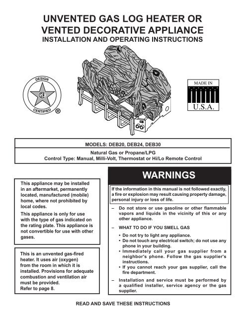
UNVENTED GAS LOG HEATER OR<br />
VENTED DECORATIVE APPLIANCE<br />
INSTALLATION AND OPERATING INSTRUCTIONS<br />
MODELS: DEB20, DEB24, DEB30<br />
Natural Gas <strong>or</strong> Propane/LPG<br />
Control Type: Manual, Milli-Volt, Thermostat <strong>or</strong> Hi/Lo Remote Control<br />
This appliance may be installed<br />
in an aftermarket, permanently<br />
located, manufactured (mobile)<br />
home, where not prohibited by<br />
local codes.<br />
This appliance is only f<strong>or</strong> use<br />
with the type of <strong>gas</strong> indicated on<br />
the rating plate. This appliance is<br />
not convertible f<strong>or</strong> use with other<br />
<strong>gas</strong>es.<br />
This is an <strong>un<strong>vented</strong></strong> <strong>gas</strong>-fired<br />
<strong>heater</strong>. It uses air (oxygen)<br />
from the room in which it is<br />
installed. Provisions f<strong>or</strong> adequate<br />
combustion and ventilation air<br />
must be provided.<br />
Refer to page 8.<br />
WARNINGS<br />
If the inf<strong>or</strong>mation in this manual is not followed exactly,<br />
a fire <strong>or</strong> explosion may result causing property damage,<br />
personal injury <strong>or</strong> loss of life.<br />
– Do not st<strong>or</strong>e <strong>or</strong> use <strong>gas</strong>oline <strong>or</strong> other flammable<br />
vap<strong>or</strong>s and liquids in the vicinity of this <strong>or</strong> any<br />
other appliance.<br />
– WHAT TO DO IF YOU SMELL GAS<br />
• Do not try to light any appliance.<br />
• Do not touch any electrical switch; do not use any<br />
phone in your building.<br />
• Immediately call your <strong>gas</strong> supplier from a<br />
neighb<strong>or</strong>'s phone. Follow the <strong>gas</strong> supplier's<br />
instructions.<br />
• If you cannot reach your <strong>gas</strong> supplier, call the<br />
fire department.<br />
– Installation and service must be perf<strong>or</strong>med by<br />
a qualified installer, service agency <strong>or</strong> the <strong>gas</strong><br />
supplier.<br />
READ AND SAVE THESE INSTRUCTIONS
CONTENTS<br />
Imp<strong>or</strong>tant Safety Inf<strong>or</strong>mation ..................................3<br />
Getting Started..........................................................5<br />
Product Features and Specifications ....................6<br />
Natural Gas .........................................................6<br />
Propane/LP..........................................................6<br />
Ignition Controls...................................................7<br />
Pilot......................................................................7<br />
Thermal Generat<strong>or</strong> ..............................................7<br />
General Installation Inf<strong>or</strong>mation ............................7<br />
Codes ..................................................................7<br />
Adequate Combustion and Ventilation Air ...........7<br />
Fireplace and Hearth Dimensions .......................10<br />
Placement in a Fireplace with a Restrictive Barrier<br />
........................................................................... 11<br />
Clearances and Height Requirements .................12<br />
Flo<strong>or</strong> Clearance .....................................................17<br />
Fireplace Preparation ............................................18<br />
Installing Vented Applications .............................19<br />
Connecting the Gas ...............................................20<br />
Checking Gas Pressure ........................................21<br />
Manual Control ..................................................21<br />
Milli-Volt/Thermostat Control .............................21<br />
Hi/Lo Control......................................................21<br />
Electrical Wiring (Milli-volt) ...................................22<br />
Connecting Remote Receiver............................23<br />
Installing Thermostat Sens<strong>or</strong>.............................23<br />
Operation of Thermostat Sens<strong>or</strong> .......................25<br />
Log Placement .......................................................26<br />
Placing the Dec<strong>or</strong>ative Rock .............................27<br />
Flame Appearance..................................................27<br />
Milli-Volt/Thermostat Control .............................27<br />
Manual Control ..................................................27<br />
Hi/Lo Control......................................................27<br />
Checking Burner Flames ......................................28<br />
Operating Instructions...........................................29<br />
F<strong>or</strong> Your Safety Read Bef<strong>or</strong>e Lighting ...............29<br />
Manual Control Lighting Instructions ................30<br />
Milli-Volt/Thermostat Control<br />
Lighting Instructions...........................................31<br />
Hi/Lo Control Lighting Instructions.....................32<br />
Match Lighting Instructions ................................33<br />
Cleaning Instructions.............................................33<br />
Troubleshooting .....................................................34<br />
Illustrated parts breakdown .................................34<br />
Replacement Parts .................................................36<br />
Burner Assembly ...............................................36<br />
Logs...................................................................38<br />
Warranty ....................................................Back page<br />
2 44D0060
IMPORTANT SAFETY INFORMATION<br />
INSTALLER<br />
Please leave these instructions with the appliance.<br />
OWNER<br />
Please retain these instructions f<strong>or</strong> future reference.<br />
IMPORTANT<br />
Read these instructions carefully bef<strong>or</strong>e installing <strong>or</strong> trying to operate this vent-free <strong>gas</strong> <strong>heater</strong>.<br />
WARNING<br />
• Any change to this <strong>heater</strong> <strong>or</strong> its controls can be dangerous.<br />
• Improper installation <strong>or</strong> use of the <strong>heater</strong> can cause serious injury <strong>or</strong> death from fire,<br />
burns, explosion <strong>or</strong> carbon monoxide poisoning.<br />
• Do not allow fans to blow directly into the fireplace. Avoid any drafts that alter<br />
burner flame patterns.<br />
• Do not use a blower insert, heat exchanger insert <strong>or</strong> other access<strong>or</strong>y, not approved<br />
f<strong>or</strong> use with this <strong>heater</strong> where applicable.<br />
1. Due to high temperatures, the appliance should<br />
be located out of traffic and away from furniture<br />
and draperies.<br />
2. Children and adults should be alerted to the hazard<br />
of high surface temperature and should stay away to<br />
avoid burns <strong>or</strong> clothing ignition.<br />
3. Young children should be carefully supervised when<br />
they are in the same room with the appliance.<br />
4. Do not place clothing <strong>or</strong> other flammable material<br />
on <strong>or</strong> near the appliance.<br />
5. Any safety screen <strong>or</strong> guard removed f<strong>or</strong> servicing an<br />
appliance, must be replaced pri<strong>or</strong> to operating the<br />
<strong>heater</strong>.<br />
6. Installation and repair should be done by a qualified<br />
service person.<br />
7. To prevent malfunction and/<strong>or</strong> sooting, an <strong>un<strong>vented</strong></strong><br />
<strong>gas</strong> <strong>heater</strong> should be cleaned bef<strong>or</strong>e use and at least<br />
annually by a professional service person. M<strong>or</strong>e frequent<br />
cleaning may be required due to excessive lint<br />
from carpeting, bedding material, etc. It is imperative<br />
that control compartments, burners and circulating air<br />
passageways be kept clean.<br />
8. CARBON MONOXIDE POISONING: Early signs of<br />
carbon monoxide poisoning are similar to the flu with<br />
headaches, dizziness and/<strong>or</strong> nausea. If you have these<br />
signs, obtain fresh air immediately. Have the <strong>heater</strong><br />
serviced as it may not be operating properly.<br />
10. This unit complies with ANSI Z21.11.2-2001 Un<strong>vented</strong><br />
Heaters and also complies with ANSI Z21.60-2000 Dec<strong>or</strong>ative<br />
Vented Appliances f<strong>or</strong> Solid Fuel Burning Fireplaces.<br />
State and local codes may only allow operation<br />
of this appliance in a <strong>vented</strong> configuration. Check your<br />
state <strong>or</strong> local codes. F<strong>or</strong> <strong>vented</strong> operation, see “Vented<br />
Instructions” in this manual.<br />
11. Do not install the <strong>heater</strong>s in a bathroom <strong>or</strong> bedroom.<br />
12. C<strong>or</strong>rect installation of the ceramic fiber <strong>log</strong>s, proper<br />
location of the <strong>heater</strong>, and annual cleaning are necessary<br />
to avoid potential problems with sooting. Sooting,<br />
resulting from improper installation <strong>or</strong> operation,<br />
can settle on surfaces outside the fireplace. See <strong>log</strong><br />
placement instructions f<strong>or</strong> proper installation.<br />
13. Avoid any drafts that alter burner flame patterns. Do not<br />
allow fans to blow directly into fireplace. Do not place<br />
a blower inside burn area of firebox. Ceiling fans may<br />
create drafts that alter burner flame patterns. Sooting<br />
and improper burning will occur.<br />
14. Caution: Candles, incense, oil lamps, etc. produce<br />
combustion byproducts including soot. Vent-free<br />
appliances will not filter <strong>or</strong> clean soot produced by<br />
these types of products. In addition, the smoke and/<strong>or</strong><br />
aromatics (scents) may be reburnt in the vent-free<br />
appliance which can produce od<strong>or</strong>s. It is recommended<br />
to minimize the use of candles, incense, etc. while the<br />
vent-free appliance is in operation.<br />
15. This is an <strong>un<strong>vented</strong></strong> <strong>gas</strong>-fired <strong>heater</strong>. It uses air (oxygen)<br />
from the room in which it is installed. Provisions f<strong>or</strong><br />
adequate combustion and ventilation air must be provided.<br />
See page 8.<br />
9. The installation must conf<strong>or</strong>m with local codes <strong>or</strong>, in<br />
the absence of local codes, with the National Fuel Gas<br />
Code, ANSI Z223.l/NFPA54. Continued on page 4<br />
44D0060 3
IMPORTANT SAFETY INFORMATION<br />
Continued from page 3<br />
16. Keep room area clear and free from combustible materials,<br />
<strong>gas</strong>oline and other flammable vap<strong>or</strong>s and liquids.<br />
17. Un<strong>vented</strong> <strong>gas</strong> <strong>heater</strong>s are a supplemental zone <strong>heater</strong>.<br />
They are not intended to be the primary heating appliance.<br />
18. Un<strong>vented</strong> <strong>gas</strong> <strong>heater</strong>s emit moisture into the living area.<br />
In most homes of average construction, this does not pose<br />
a problem. In houses of extremely tight construction,<br />
additional mechanical ventilation is recommended.<br />
19. During manufacturing, fabricating and shipping, various<br />
components of this appliance are treated with certain<br />
oils, films <strong>or</strong> bonding agents. These chemicals are not<br />
harmful but may produce annoying smoke and smells<br />
as they are burned off during the initial operation<br />
of the appliance; possibly causing headaches <strong>or</strong> eye<br />
<strong>or</strong> lung irritation. This is a n<strong>or</strong>mal and temp<strong>or</strong>ary<br />
occurrence.<br />
The initial break-in operation should last two to three<br />
hours with the burner at the highest setting. Provide<br />
maximum ventilation by opening windows <strong>or</strong> do<strong>or</strong>s to<br />
allow od<strong>or</strong>s to dissipate. Any od<strong>or</strong>s remaining after this<br />
initial break-in period will be slight and will disappear<br />
with continued use.<br />
20. Input ratings are shown in BTU per hour and are f<strong>or</strong><br />
elevations up to 2,000 feet. F<strong>or</strong> elevations above 2,000<br />
feet, input ratings should be reduced 4 percent f<strong>or</strong><br />
each 1,000 feet above sea level. Refer to the National<br />
Fuel Gas Code.<br />
21. The appliance and its appliance main <strong>gas</strong> valve must be<br />
disconnected from the <strong>gas</strong> supply piping system during<br />
any pressure testing of that system at test pressures in<br />
excess of 1/2 psig (3.5 kPa).<br />
22. The appliance must be isolated from the <strong>gas</strong> supply<br />
piping system by closing its equipment shutoff valve<br />
during any pressure testing of the <strong>gas</strong> supply piping<br />
system at test pressures equal to <strong>or</strong> less than 1/2 psig<br />
(3.5 kPa).<br />
23. Do not use this room <strong>heater</strong> if any part has been under<br />
water. Immediately call a qualified service technician<br />
to inspect the room <strong>heater</strong> and to replace any part of the<br />
control system and any <strong>gas</strong> control which has been under<br />
water.<br />
24. This appliance must not be used with glass do<strong>or</strong>s in the<br />
closed position. This can lead to pilot outages and severe<br />
sooting outside the fireplace.<br />
25. Never burn solid fuels in a fireplace where a <strong>un<strong>vented</strong></strong><br />
room <strong>heater</strong> is installed.<br />
26. Always have a fireplace screen in place when the appliance<br />
is in operation and, unless other provisions f<strong>or</strong><br />
combustion air are provided, the screen must have an<br />
opening(s) f<strong>or</strong> induction of combustion air.<br />
4 44D0060
GETTING STARTED<br />
MAKE SURE YOU HAVE RECEIVED ALL PARTS:<br />
Check your packing list to verify that all listed parts have been received. You should have the following:<br />
• Un<strong>vented</strong> <strong>gas</strong> <strong>log</strong> grate/burner assembly<br />
• Two (2) Plastic bags containing crushed volcanic rock<br />
• Installation/operating instructions<br />
• Ceramic Fiber <strong>log</strong>s<br />
• Two (2) anch<strong>or</strong>ing screws<br />
The milli-volt controlled version of this <strong>heater</strong> is the only style designed to be operated with optional devices f<strong>or</strong><br />
ON/OFF functions. The following options may be used with the milli-volt controlled <strong>heater</strong>. These options are not<br />
packaged with the <strong>log</strong> set.<br />
• Hand held Remote with receiver<br />
• Wall thermostat with 15' wire<br />
• Wall switch with 15' wire<br />
• Hand held Thermostat Remote with receiver<br />
• Thermostat sens<strong>or</strong><br />
The following options may be used with Hi/Lo control <strong>heater</strong>.<br />
• Hand held Remote with receiver<br />
CAUTION<br />
• Handle the <strong>gas</strong> <strong>log</strong> burner assembly by the grate only. Do not pick the unit up<br />
by the burners.<br />
• Gloves are recommended when handling ceramic fiber <strong>log</strong>s to prevent skin irritation<br />
from loose fibers. Logs are fragile — handle with care.<br />
Carefully inspect the contents f<strong>or</strong> shipping damage. If any parts are missing <strong>or</strong> damaged, immediately inf<strong>or</strong>m the<br />
dealer from whom you purchased the appliance. Do not attempt to install any part of the appliance unless you<br />
have all parts in good condition.<br />
WHAT YOU WILL NEED FOR INSTALLATION:<br />
You should have the following items available bef<strong>or</strong>e proceeding with installation:<br />
• External regulat<strong>or</strong> (f<strong>or</strong> propane/LPG and 1/2 lb. natural <strong>gas</strong> systems only)<br />
• Piping which complies with local codes<br />
• Screwdriver<br />
• Sediment trap (recommended)<br />
• Tee joint.<br />
• Pipe sealant approved f<strong>or</strong> use with propane/LPG (Resistant to sulfur compounds)<br />
• Drill with 5/32 bit<br />
• Manual shutoff valve<br />
• Pipe wrench <strong>or</strong> appropriate size crescent wrench set<br />
44D0060 5
PRODUCT FEATURES AND SPECIFICATIONS<br />
NATURAL GAS<br />
NOTE: An external regulat<strong>or</strong> is required to reduce supply pressure to a maximum of 10 1 /2" W.C. (11"<br />
W.C. f<strong>or</strong> HI/LO) on natural <strong>gas</strong> systems operating at higher pressure.<br />
Manual Pressure Milli-Volt and T-Stat Pressure Hi/Lo Pressure<br />
Regulat<strong>or</strong> Pressure: Setting: 3.0" w.c. Regulat<strong>or</strong> Pressure Setting: 3.5" w.c. Regulat<strong>or</strong> Pressure Setting: 3.5" w.c.<br />
Pilot Regulat<strong>or</strong>: 3.5" w.c.<br />
Pilot Regulat<strong>or</strong>: 3.5" w.c.<br />
Gas Inlet Pressure: Max. 10 1 /2" w.c. Gas Inlet Pressure: 10 1 /2" w.c. Gas Inlet Pressure: Max. 11" w.c.<br />
Min. 5" w.c. Min. 5" w.c. Min. 6" w.c.<br />
Gas Rate<br />
Model Number Control Max BTU/Hr Min BTU/Hr<br />
DEB20NM MANUAL 28,000 18,000<br />
DEB24NM MANUAL 38,000 20,000<br />
DEB30NM MANUAL 38,000 20,000<br />
DEB20NV MILLI-VOLT 28,000 18,000<br />
DEB24NV MILLI-VOLT 38,000 25,000<br />
DEB30NV MILLI-VOLT 38,000 25,000<br />
DEB20NH HI/LO 28,000 18,000<br />
DEB24NH HI/LO 38,000 20,000<br />
DEB30NH HI/LO 38,000 20,000<br />
DEB20NT THERMOSTAT 28,000 18,000<br />
DEB24NT THERMOSTAT 38,000 25,000<br />
DEB30NT THERMOSTAT 38,000 25,000<br />
PROPANE/LPG<br />
Note: An external regulat<strong>or</strong> is required to reduce supply pressure to a maximum of 13" w.c.<br />
Manual Pressure Milli-Volt and T-Stat Pressure Hi/Lo Pressure<br />
Regulat<strong>or</strong> Pressure Setting: 10" w.c. Regulat<strong>or</strong> Pressure Setting: 10" w.c. Regulat<strong>or</strong> Pressure Setting: 10" w.c.<br />
Gas Inlet Pressure: Max. 13" w.c. Gas Inlet Pressure: Max. 13" w.c. Gas Inlet Pressure: Max. 13: w.c.<br />
Min. 11" w.c. Min. 11" w.c. Min. 12" w.c.<br />
Gas Rate<br />
Model Number Control Max BTU/Hr Min BTU/Hr<br />
DEB20PM MANUAL 28,000 18,000<br />
DEB24PM MANUAL 38,000 20,000<br />
DEB30PM MANUAL 38,000 20,000<br />
DEB20PV MILLI-VOLT 28,000 20,000<br />
DEB24 PV MILLI-VOLT 38,000 30,000<br />
DEB30PV MILLI-VOLT 38,000 30,000<br />
DEB20PH HI/LO 28,000 21,000<br />
DEB24PH HI/LO 38,000 22,000<br />
DEB30PH HI/LO 38,000 22,000<br />
DEB20PT THERMOSTAT 28,000 20,000<br />
DEB24PT THERMOSTAT 38,000 30,000<br />
DEB30PT THERMOSTAT 38,000 30,000<br />
6 44D0060
PRODUCT FEATURES AND SPECIFICATIONS<br />
IGNITION CONTROLS<br />
Piezo ignit<strong>or</strong> allows ignition of the pilot without the use of matches <strong>or</strong> batteries.<br />
Manual control has three (3) positions:<br />
OFF - All <strong>gas</strong> to the <strong>gas</strong> <strong>log</strong>s is shut off at the valve.<br />
IGN - Valve position to light/maintain a standing pilot.<br />
HI/LOW - Variable position c<strong>or</strong>responding to desired flame height.<br />
Hi/Lo remote control valve has five (5) positions:<br />
OFF - All <strong>gas</strong> to the <strong>gas</strong> <strong>log</strong>s is shut off at the valve.<br />
IGN - Position not used on this <strong>log</strong> set.<br />
PILOT - Valve position to light/maintain a standing pilot.<br />
ON - Valve position to turn ON.<br />
HI/LOW - Variable position c<strong>or</strong>responding from pilot only to desired flame height.<br />
Milli-Volt and T-Stat control has four (4) positions:<br />
OFF - All <strong>gas</strong> to the <strong>gas</strong> <strong>log</strong>s is shut off at the valve.<br />
IGN - Valve position to light/maintain a standing pilot.<br />
ON - Valve position to turn ON/OFF <strong>log</strong> set with remote switch/thermostat.<br />
LOW/HI - Variable position to control flame height (heat output).<br />
PILOT/ODS<br />
The <strong>gas</strong> <strong>log</strong> <strong>heater</strong> is fitted with a specially designed safety pilot (ODS assembly) which senses the amount of oxygen available<br />
in the room and shuts the <strong>gas</strong> <strong>log</strong> <strong>heater</strong> off if the oxygen level begins to drop below a satisfact<strong>or</strong>y level. The pilot can<br />
only be relit when adequate fresh air is available.<br />
THERMAL GENERATOR<br />
The milli-volt/t-stat <strong>gas</strong> <strong>log</strong> pilot is fitted with a milli-volt (thermopile) generat<strong>or</strong> to provide power f<strong>or</strong> remote activation.<br />
44D0060 7
GENERAL INSTALLATION INFORMATION<br />
CODES<br />
Adhere to all local codes <strong>or</strong>, in their absence, the latest edition of THE NATIONAL FUEL GAS CODE ANSI Z223.1<br />
<strong>or</strong> NFPA54 which can be obtained from…<br />
American National Standards Institute, Inc.<br />
1430 Broadway<br />
New Y<strong>or</strong>k, NY 10018<br />
<strong>or</strong><br />
National Fire Protection Association, Inc.<br />
Batterymarch Park<br />
Quincy, MA 02269<br />
ADEQUATE COMBUSTION AND VENTILATION AIR<br />
This <strong>heater</strong> shall not be installed in a confined space <strong>or</strong> unusually tight construction unless provisions are provided<br />
f<strong>or</strong> adequate combustion and ventilation air.<br />
The National Fuel Gas Code, (ANSI Z223.1/NFPA 54), defines a confined space as a space whose volume is less than 50<br />
cubic feet per 1,000 BTU per hour (4.8 m 3 per kw) of the aggregate input rating of all appliances installed in that space. An<br />
unconfined space is defined as a space whose volume is not less than 50 cubic feet per 1,000 BTU per hour (4.8 m 3 per kw)<br />
of the aggregate input rating of all appliances installed in that space. Rooms communicating directly with the space in which<br />
the appliances are installed, through openings not furnished with do<strong>or</strong>s, are considered a part of the unconfined space.<br />
UNUSUALLY TIGHT CONSTRUCTION IS DEFINED AS CONSTRUCTION WHERE…<br />
a) walls and ceilings exposed to the outside atmosphere have a continuous water vap<strong>or</strong> retarder with a rating of 1 perm<br />
(6 x 10 11 kg per pa-sec-m 2 ) <strong>or</strong> less with openings <strong>gas</strong>keted <strong>or</strong> sealed;<br />
b) weather striping has been added on openable windows and do<strong>or</strong>s, and<br />
c) caulking <strong>or</strong> sealants are applied to areas such as joints around window and do<strong>or</strong> frames, between sole plates<br />
and flo<strong>or</strong>s, between wall-ceiling joints, between wall panels, at penetrations f<strong>or</strong> plumbing, electrical, and <strong>gas</strong><br />
lines, and at other openings.<br />
8 44D0060
GENERAL INSTALLATION INFORMATION<br />
Counter<br />
Fireplace<br />
<br />
<br />
Figure 1 - Example of a Large Room with 1/2 Wall Divider<br />
The following f<strong>or</strong>mula can be used to determine the maximum <strong>heater</strong> rating per the definition of unconfined space:<br />
BTU/Hr = (L1 + L2) Ft x (W) Ft x (H) Ft<br />
50<br />
x 1000<br />
Consider two connecting rooms with an open area between, with the following dimensions:<br />
L1 = 15 1 /2 Ft., L2 = 12 Ft., W = 12 Ft., H = 8 Ft.<br />
BTU/Hr = (15 1 /2 + 12) x (12) x (8)<br />
50<br />
x 1000 = 52800 BTU/Hr<br />
If there were a do<strong>or</strong> between the two rooms the calculation would be based only on the room with the <strong>heater</strong>.<br />
BTU/Hr = (15 1 /2) x (12) x (8)<br />
50<br />
x 1000 = 29760 BTU/Hr<br />
WARNING<br />
If the area in which the <strong>heater</strong> may be operated is smaller than that defined as an<br />
unconfined space <strong>or</strong> if the building is of unusually tight construction, provide adequate<br />
combustion and ventilation air by one of the methods described in the National Fuel<br />
Gas Code, ANSI Z223.1/NFPA 54, Section 5.3 <strong>or</strong> applicable local codes.<br />
44D0060 9
FIREPLACE AND HEARTH DIMENSIONS<br />
WARNING<br />
This appliance is f<strong>or</strong> installation only in a solid-fuel burning masonry <strong>or</strong> UL127<br />
fact<strong>or</strong>y-built fireplace <strong>or</strong> in a listed ventless firebox enclosure. It has been design<br />
certified f<strong>or</strong> these installations.<br />
Exception: DO NOT install this appliance in a fact<strong>or</strong>y-built fireplace that includes<br />
instructions stating it has not been tested <strong>or</strong> should not be used with <strong>un<strong>vented</strong></strong><br />
<strong>gas</strong> <strong>log</strong>s.<br />
Use manufacturer's installation and clearance requirements as defined in their manual.<br />
The DEB Series <strong>un<strong>vented</strong></strong> room <strong>heater</strong> is approved f<strong>or</strong> installation into the following <strong>un<strong>vented</strong></strong> fireplaces:<br />
GCUF Series Fireboxes 32, 36, <strong>or</strong> 42<br />
The DEB Series <strong>un<strong>vented</strong></strong> room <strong>heater</strong> may also be installed into a Ventless Firebox Enclosure f<strong>or</strong> Gas Fired Dec<strong>or</strong>ative Type<br />
Un<strong>vented</strong> Room Heaters per IAS Requirement No. 2-97 ANSI Z21.91-2001 (typically referred to as a "Universal Firebox"),<br />
as long as firebox hearth dimensions meet the minimum hearth dimensions shown below.<br />
<br />
Model A B C D<br />
DEB20 18" 13 1 /4" 27" 17"<br />
DEB24 22 1 /4" 13 1 /4" 28 1 /2" 17"<br />
DEB30 25 1 /2" 13 1 /4" 32 1 /2" 17"<br />
<br />
<br />
<br />
Figure 2 - Hearth Minimum Dimension<br />
10 44D0060
PLACEMENT IN A FIREPLACE WITH A RESTRICTIVE BARRIER<br />
IMPORTANT INFORMATION FOR THE INSTALLATION OF THIS GAS LOG SET<br />
The following are guidelines f<strong>or</strong> placing a <strong>gas</strong> <strong>log</strong> set in a fireplace that has a restrictive barrier along the bottom front opening<br />
of the fireplace. Some examples of barriers are glass/screen do<strong>or</strong> frames and sunken/recessed fireplaces.<br />
Height of Restriction (X)<br />
Minimum Depth of Fireplace/Firebox<br />
No restriction 13 1 /4"<br />
0 to 1 1 /2" 16"<br />
From 1 1 /2" to 3" 16"<br />
Greater than 3" ANY BARRIER GREATER THAN THREE INCHES (3")<br />
PLACED IN FRONT OF THE GAS LOG SET IS NOT<br />
RECOMMENDED BY THE MANUFACTURER.<br />
Glass do<strong>or</strong> frames<br />
with adjustable<br />
louvers should have<br />
the louvers fully<br />
open while the unit is<br />
in operation.<br />
The <strong>log</strong> set should be<br />
placed against <strong>or</strong> as near<br />
as possible to the rear wall<br />
of the fireplace/firebox.<br />
Height of restrictive barrier<br />
caused by glass do<strong>or</strong> frames,<br />
recessed fireplaces, etc. from the<br />
base <strong>or</strong> bottom surface of the<br />
unit. (Refer to Table).<br />
X<br />
Depth of fireplace/firebox.<br />
(Refer toTable).<br />
Figure 3 - Reference Drawing of a Natural Flame Log Set in an Enclosure<br />
WARNING<br />
Barriers such as the bottom of a glass do<strong>or</strong> frame placed in front of a <strong>gas</strong> <strong>log</strong> set<br />
can change the air flow characteristics of the fireplace which in turn can cause the<br />
unit to overheat and malfunction.<br />
NOTE: Non combustible material such as refract<strong>or</strong>y brick may be used to line the flo<strong>or</strong> of the fireplace<br />
in <strong>or</strong>der to raise the height of the <strong>gas</strong> <strong>log</strong> set in relation to a restrictive barrier. If the unit is raised, the<br />
minimum height dimension listed in the homeowner’s manual must not be exceeded.<br />
NOTE: If the <strong>log</strong> set is equipped with a remote receiver, a restrictive barrier may reduce the battery life<br />
by increasing the ambient temperature inside the fireplace. Placement of the receiver outside of the<br />
fireplace will extend the battery life.<br />
44D0060 11
CLEARANCES AND HEIGHT REQUIREMENTS<br />
WARNING<br />
The dimensions shown in Figures 4 through 12 and defined in the fireplace manufacturer's<br />
instructions are minimum clearances to maintain when installing this <strong>heater</strong>. Left and<br />
right clearances are determined when facing the front of the <strong>heater</strong>.<br />
When <strong>heater</strong> is installed into a ventless firebox, minimum clearances, as specified by<br />
the ventless firebox manufacturer, must be met.<br />
Follow these instructions carefully to ensure safe installation. Failure to follow<br />
instructions exactly can create a fire hazard.<br />
Sidewall and ceiling clearances: The sides of the fireplace opening must be at least 16" from any combustible wall.<br />
The ceiling must be at least 42" from the top of the fireplace opening.<br />
<br />
<br />
Figure 4 - Sidewall and Ceiling Clearances<br />
12 44D0060
CLEARANCES and HEIGHT REQUIREMENTS<br />
Heat resistant material (minimum requirements) with no wooden mantel <strong>or</strong> other combustible projection:<br />
To install the <strong>gas</strong> <strong>log</strong>s into a fireplace with no wooden mantel, shelf <strong>or</strong> other combustible projection above the fireplace<br />
opening, measure the heat resistant material height, per Figure 5, then see TABLE A.<br />
Heat resistant materials such as slate and marble must be at least 1/2” thick. Sheet metal should not be installed<br />
onto combustible material.<br />
IMPORTANT: If you cannot meet these minimum clearances you must operate the <strong>heater</strong> with chimney flue damper open.<br />
Refer to “Installing Vented Applications” found on page 18.<br />
<br />
<br />
<br />
<br />
<br />
<br />
<br />
<br />
<br />
Figure 5 - Measuring Heat Resistant Material<br />
HEAT RESISTANT<br />
REQUIREMENTS FOR SAFE INSTALLATION<br />
MATERIAL<br />
MEASUREMENT DEB20 DEB24 and DEB30<br />
12" <strong>or</strong> m<strong>or</strong>e Hood not required. Hood not required.<br />
8" to less than 12" Hood not required. Extend heat resistent material to 12"<br />
<strong>or</strong> install hood. See Figure 5.<br />
Less than 8" Extend heat resistant Extend heat resistant material to at<br />
material to at least 8" least 8" and install hood. See Figure<br />
and install hood.<br />
5. OR, extend heat resistant mater-<br />
See Figure 5. ial to a height of at least 12".<br />
TABLE A - Heat Resistant Material Requirements with no Mantel <strong>or</strong> Combustible Projection<br />
44D0060 13
CLEARANCES and HEIGHT REQUIREMENTS<br />
Heat resistant material (minimum requirements) with wooden mantel <strong>or</strong> other combustible projection:<br />
To install the <strong>heater</strong> with a wooden mantel, shelf <strong>or</strong> other combustible projection above, first measure the heat resistant<br />
material shown in Figure 6, then refer to Table B.<br />
<br />
<br />
<br />
<br />
<br />
<br />
<br />
Figure 6 - Measuring Heat Resistant Material f<strong>or</strong> Mantel<br />
HEAT RESISTANT<br />
MATERIAL<br />
MEASUREMENT<br />
REQUIREMENTS FOR SAFE INSTALLATION WITH WOODEN MANTEL,<br />
SHELF OR OTHER COMBUSTIBLE PROJECTION<br />
DEB20<br />
DEB24 and DEB30<br />
12" <strong>or</strong> m<strong>or</strong>e Hood not required. Observe profiles (side Hood not required. Observe profile (side<br />
elevations) shown in Figure 7, page 15. elevations) shown in Figure 9, page 16.<br />
8" to less than 12" Install hood and observe profiles shown Install hood and observe profiles shown<br />
in Figure 8, page 15; OR extend heat in Figure 7, page 15; OR extend heat<br />
resistant material to at least 12" and observe resistant material to at least 12" and observe<br />
profiles shown in Figure 7, page 15. profiles shown in Figure 9, page 16.<br />
Less than 8" Extend heat resistant material to at least Extend heat resistant material to at least<br />
8", install hood and observe profiles shown 8", install hood and observe profiles shown<br />
in Figure 8, page 15; OR extend heat in Figure 7, page 15; OR extend heat<br />
resistant material to at least 12" and observe resistant material to at least 12" and observe<br />
profiles shown in Figure 8, page 15. profiles shown in Figure 9, page 16.<br />
TABLE B - Heat Resistant Material Heights and Mantel Location<br />
14 44D0060
CLEARANCES AND HEIGHT REQUIRMENTS<br />
<br />
<br />
<br />
<br />
<br />
<br />
<br />
<br />
<br />
<br />
<br />
Example: A mantel may project from the wall a maximum of 2 1 /2" at a<br />
minimum of 14" above the opening, and a maximum of 6" at a<br />
minimum of 20 1 /2" above the opening.<br />
Figure 7 - Minimum Mantel Clearance with No Hood - DEB20<br />
<br />
<br />
<br />
<br />
<br />
<br />
<br />
<br />
<br />
<br />
<br />
<br />
<br />
Example: A mantel may project from the wall a maximum of 2 1 /2" at a<br />
minimum of 8" above the opening, and a maximum of 6" at a<br />
minimum of 14 1 /2" above the opening.<br />
Figure 8 - Minimum Mantel Clearance with Hood - All Models<br />
44D0060 15
CLEARANCES AND HEIGHT REQUIRMENTS<br />
<br />
<br />
<br />
<br />
<br />
<br />
<br />
<br />
Example: The bottom of the mantel may project from the wall a<br />
maximum of 10" at a minimum of 28" above the<br />
Figure 9 - Minimum Mantel Clearance with No Hood — DEB24 and DEB30<br />
<br />
<br />
Figure 10 is an example of an unsafe mantel installation.<br />
This mantel projects 4" at 8" above the opening, exceeding<br />
the maximum acceptable distance of 2 1 /2" The mantel also<br />
projects 7" at 14 1 /2" above the opening, exceeding the<br />
maximum acceptable distance of 6".<br />
<br />
<br />
<br />
<br />
If your mantel profile is unsafe, you may either:<br />
• Raise the mantel to an acceptable height<br />
OR<br />
• Remove the mantel<br />
Figure 10 - Minimum Mantel Clearance with No Hood - DEB24 and DEB30<br />
(Example of Unsafe Installation)<br />
16 44D0060
FLOOR CLEARANCE<br />
The <strong>gas</strong> <strong>log</strong> <strong>heater</strong> must be installed at least 5" above any combustible flo<strong>or</strong>ing material, such as carpeting <strong>or</strong> tile,<br />
which is closer than 14" to the base of the fireplace. The minimum distance must be maintained from the top surface<br />
of carpeting, tile, etc. See Figure 11.<br />
OR,<br />
The <strong>gas</strong> <strong>log</strong> <strong>heater</strong> may be installed nearer to the flo<strong>or</strong> if a minimum of 14" of noncombustible material such as slate <strong>or</strong><br />
marble is installed between the base of the fireplace and the combustible flo<strong>or</strong>ing. See Figure 12.<br />
<br />
<br />
<br />
<br />
<br />
<br />
Figure 11 - Minimum Clearance above Combustible Flo<strong>or</strong>ing<br />
<br />
<br />
<br />
<br />
<br />
<br />
<br />
<br />
<br />
Figure 12 - Minimum Clearance above Combustible Flo<strong>or</strong>ing with<br />
Noncombustible Material Installed at Base of Fireplace<br />
44D0060 17
FIREPLACE PREPARATION<br />
BEFORE FULLY INSTALLING THE UNIT:<br />
• Turn OFF the <strong>gas</strong> supply to the fireplace <strong>or</strong> firebox.<br />
• Seal any fresh air vents and/<strong>or</strong> ash clean-out do<strong>or</strong>s located on the flo<strong>or</strong> <strong>or</strong> wall of the fireplace. If left unsealed, drafting<br />
may cause pilot outage <strong>or</strong> sooting. Use a heat resistant sealant. Do not seal the chimney flue damper.<br />
WARNING<br />
Bef<strong>or</strong>e installing in a solid fuel burning<br />
fireplace, The chimney flue and firebox<br />
must be cleaned of soot, creosote,<br />
ashes and loose paint by a qualified<br />
chimney cleaner.<br />
INSTALLING VENTED APPLICATIONS<br />
Manual, milli-volt and Hi/Lo controlled <strong>gas</strong> <strong>log</strong>s may be installed as a <strong>vented</strong> dec<strong>or</strong>ative <strong>log</strong> set in compliance with ANSI<br />
Z21.60 and National Fuel Gas Code, Section 6.6. Since, the <strong>gas</strong> <strong>log</strong>s are operated with the damper open, non-combustible<br />
material and minimum mantel requirements do not apply.<br />
WARNING<br />
This appliance is f<strong>or</strong> installation only in a solid fuel burning fireplace (masonry fireplace<br />
<strong>or</strong> manufactured fireplace) with a w<strong>or</strong>king flue and constructed of noncombustible<br />
material.<br />
Exception: DO NOT install this appliance in a fact<strong>or</strong>y-built fireplace that includes<br />
instructions stating that it has not been tested <strong>or</strong> should not be used with <strong>un<strong>vented</strong></strong><br />
<strong>gas</strong> <strong>log</strong>s. This <strong>log</strong> set may be installed as a <strong>vented</strong> <strong>log</strong> set.<br />
BEFORE INSTALLING THE APPLIANCE:<br />
• Turn off <strong>gas</strong> supply to fireplace <strong>or</strong> firebox.<br />
• Have the fireplace flo<strong>or</strong> and chimney professionally cleaned to remove ashes, soot, creosote <strong>or</strong> other obstructions.<br />
Have this cleaning perf<strong>or</strong>med annually after installation.<br />
• Seal any fresh air vents <strong>or</strong> ash clean-out do<strong>or</strong>s located on flo<strong>or</strong> <strong>or</strong> wall of fireplace. If not, drafting may cause pilot<br />
outage <strong>or</strong> sooting. Use a heat-resistant sealant.<br />
Install and operate the appliance as directed in this manual.<br />
DAMPER STOP INSTALLATION:<br />
A damper stop must be provided with the unit. Contact<br />
your dealer to obtain one. The damper stop must be<br />
installed as shown in Figure 13 to prevent full closure<br />
of the fireplace damper blade and provide a minimum<br />
29 square inch flue opening.<br />
<br />
<br />
Figure 13 - Damper Stop Installation.<br />
(See WARNING at top of next page.)<br />
18 44D0060
INSTALLING VENTED APPLICATIONS<br />
WARNING<br />
The fireplace and <strong>gas</strong> <strong>log</strong>s function as a system. If the fireplace is spilling into the room<br />
(check with a match <strong>or</strong> a smoke stick), reposition the damper clamp until a positive<br />
draft is obtained by opening the damper. If negative pressure in home prevents having<br />
a positive draft, contact your dealer f<strong>or</strong> assistance.<br />
PLACING AND SECURING APPLIANCE<br />
WARNING<br />
You must secure the <strong>gas</strong> <strong>log</strong> <strong>heater</strong> to the fireplace flo<strong>or</strong>. If not, the entire unit<br />
may move when you adjust the controls. Movement of unit may cause shifting of<br />
the <strong>gas</strong> <strong>log</strong>s which leads to sooting and improper burning. Grate movement could<br />
cause a <strong>gas</strong> leak.<br />
Special care is required if you are installing the unit into a sunken fireplace.<br />
You must raise the fireplace flo<strong>or</strong> to allow access to <strong>gas</strong> <strong>log</strong> controls. This will<br />
insure adequate air flow and guard against sooting. Raise the fireplace flo<strong>or</strong> using<br />
noncombustible materials, as described in “Placement in a Fireplace with Restrictive<br />
Barrier” on page 11.<br />
ASSEMBLY PROCEDURE:<br />
1. Center the <strong>gas</strong> <strong>log</strong> unit in the fireplace <strong>or</strong> firebox. Make certain the front feet of the grate sit inside the front edge of the<br />
fireplace <strong>or</strong> firebox.<br />
2. Anch<strong>or</strong> holes are located on the right and left sides of the unit. After centering the grate c<strong>or</strong>rectly, mark the hole positions<br />
on the fireplace/firebox flo<strong>or</strong>. Drill two (2) 5 /32" diameter holes approximately 1 1 /2" deep.<br />
3. Anch<strong>or</strong> the grate to the fireplace/firebox flo<strong>or</strong> using the screws provided. See Figure 14.<br />
Proper installation of the grate is essential to prevent any movement of the <strong>gas</strong> <strong>log</strong>s and controls during operation.<br />
Screw<br />
Screw<br />
Anch<strong>or</strong><br />
Hole<br />
Anch<strong>or</strong><br />
Hole<br />
Figure 14 - Securing Heater to Flo<strong>or</strong> of Fireplace/Firebox<br />
44D0060 19
CONNECTING THE GAS<br />
NOTICE: A qualified <strong>gas</strong> appliance installer must connect the <strong>heater</strong> to the <strong>gas</strong> supply. Consult<br />
all local codes.<br />
CAUTION<br />
Use new black iron <strong>or</strong> steel pipe. Internally tinned copper <strong>or</strong> copper tubing can be used<br />
per National Fuel Code, section 2.6.3, providing <strong>gas</strong> meets hydrogen sulfide limits,<br />
and where permitted by local codes. Gas piping system must be sized to provide<br />
minimum inlet pressure (Listed on Data Plate) at the maximum flow rate (BTU/Hr).<br />
Undue pressure loss will occur if the pipe is too small.<br />
A manual shutoff valve must be installed upstream of the appliance. Union tee<br />
and plugged 1 /8" NPT pressure tapping point should be installed upstream of the<br />
appliance. See Figure 15.<br />
To Heater<br />
Valve<br />
Pipe Coupling<br />
Pipe<br />
Locations that the Pressure<br />
Tapping Point May Be Installed<br />
Stainless<br />
Flexible Tube<br />
Manual Shutoff<br />
Valve<br />
Gas Supply<br />
Inlet<br />
Figure 15 - Gas Connection<br />
IMPORTANT: Hold <strong>heater</strong> valve firmly with a wrench to prevent movement when connecting to inlet pipe.<br />
CAUTION<br />
CHECK GAS TYPE: The <strong>gas</strong> supply must be the same as stated on the <strong>heater</strong>’s rating<br />
plate. If the <strong>gas</strong> supply is different, DO NOT INSTALL THE HEATER. Contact your<br />
dealer f<strong>or</strong> the c<strong>or</strong>rect model.<br />
Always use an external regulat<strong>or</strong> f<strong>or</strong> all propane/LPG <strong>heater</strong>s and high pressure one to two-pound systems<br />
only, to reduce the supply tank pressure to a maximum of 13" w.c. This is in addition to the internal regulat<strong>or</strong> in<br />
the <strong>heater</strong> valve.<br />
20 44D0060
WARNING<br />
Connecting directly to an<br />
unregulated propane/LPG tank<br />
can cause an explosion.<br />
CHECKING GAS PRESSURE<br />
The <strong>heater</strong> <strong>gas</strong> inlet connection is a 3 /8" NPT at the valve. On all<br />
control type units, the inlet connection is on the right side of unit.<br />
To connect from the opposite side, route the pipe around the back<br />
p<strong>or</strong>tion of the unit.<br />
When tightening up the joint to the valve, hold the valve securely<br />
to prevent movement.<br />
Test all <strong>gas</strong> joints from the <strong>gas</strong> meter to the <strong>heater</strong> valve f<strong>or</strong> leaks using a <strong>gas</strong> analyzer <strong>or</strong> soap and water solution after<br />
completing connection. DO NOT USE AN OPEN FLAME.<br />
Check the <strong>gas</strong> pressure with the appliance burning and the control set to HIGH.<br />
MANUAL CONTROL (Figure 16)<br />
The pressure regulat<strong>or</strong> is preset and locked to discourage<br />
tampering. If the pressure is not as specified,<br />
replace the regulat<strong>or</strong> with the c<strong>or</strong>rect part from the parts<br />
list in this manual.<br />
Remove 1 /8" NPT plug, located on side of regulat<strong>or</strong><br />
body. Install fitting and tubing to pressure gauge. After<br />
taking pressure reading, reinstall test plug. Check f<strong>or</strong><br />
<strong>gas</strong> leaks.<br />
NPT Test Plug<br />
Figure 16 - Pressure Test Point Location<br />
Manual Control<br />
Test P<strong>or</strong>t “OUT”<br />
MILLI-VOLT AND T-STAT CONTROL (Figure 17)<br />
The valve regulat<strong>or</strong> controls the burner pressure which<br />
should be checked at the pressure test point.<br />
Turn captured screw counter clockwise two <strong>or</strong> thre turns<br />
and then place tubing to pressure gauge over test point<br />
(Use test point “OUT” closest to control knob). After<br />
taking pressure reading, be sure and turn captured screw<br />
clockwise firmly to re-seal. Do not over t<strong>or</strong>que. Check<br />
f<strong>or</strong> <strong>gas</strong> leaks.<br />
Figure 17 - Pressure Test Point Location<br />
Milli-Volt Control<br />
HI/LO REMOTE CONTROL (Figure 18)<br />
Turn captured screw counter clockwise two <strong>or</strong> three<br />
turns. (The p<strong>or</strong>t is labeled A) Place tubing to pressure<br />
gauge over test point. After taking pressure reading, be<br />
sure to turn captured screw clockwise firmly to reseal.<br />
Do not over t<strong>or</strong>que. Check f<strong>or</strong> <strong>gas</strong> leaks.<br />
NOTE: If outlet pressure checks low, check<br />
inlet pressure. See page 6 f<strong>or</strong> c<strong>or</strong>rect<br />
pressure f<strong>or</strong> your unit.<br />
Figure 18 - Pressure Test Point Location<br />
Hi/Lo Control<br />
A “OUT”<br />
Test P<strong>or</strong>t<br />
44D0060 21
ELECTRICAL WIRING (MILLI-VOLT)<br />
The milli-volt valve is a self-powered combination <strong>gas</strong> control THAT DOES NOT REQUIRE 110 VAC TO<br />
OPERATE.<br />
CAUTION<br />
Label all wires pri<strong>or</strong> to disconnection<br />
when servicing controls. Wiring<br />
err<strong>or</strong>s can cause improper and<br />
dangerous operation. Verify proper<br />
operation after servicing.<br />
ODS<br />
Pilot<br />
On/Off<br />
Switch<br />
Wall<br />
Switch<br />
On/Off<br />
Switch<br />
TH = 3<br />
TP = 1<br />
TP/TH = 2<br />
ODS<br />
Pilot<br />
Milli-volt<br />
Valve<br />
Spade<br />
Terminal<br />
Switch<br />
CONNECTING OPTIONAL WALL SWITCH OR THERMOSTAT<br />
1. Use 18 awg, two-wire cable, 15 feet maximum length.<br />
Figure 19 - Wiring Diagram<br />
Optional Wall<br />
Switch, Remote<br />
Receiver <strong>or</strong><br />
Optional T-Stat<br />
2. At one end of the cable, connect both wires to the wall switch <strong>or</strong> thermostat. At the other end, connect one wire to<br />
TP/TH and one wire to TH, <strong>or</strong> connect the wall switch/thermostat to the two male (0.25") terminals on the left side of<br />
the unit. The col<strong>or</strong> of the wires does not matter.<br />
22 44D0060
CONNECTING REMOTE RECEIVER<br />
THESE INSTRUCTIONS SUPERCEDE THE SECTION<br />
ENTITLED “HEARTH MOUNT” IN THE MILLI-VOLT<br />
HAND-HELD REMOTE INSTRUCTIONS SUPPLIED<br />
WITH THE REMOTE.<br />
1. Cut cable to length (approximately 12") f<strong>or</strong> placement<br />
in the fireplace.<br />
2. Strip back 1 /4" of the insulation from both ends of<br />
each wire.<br />
3. Connect two .25 female connect<strong>or</strong>s to the wires at one<br />
end of the cable.<br />
4. Insert the opposite ends of the wires into the receiver<br />
wire terminals and tighten the screws.<br />
5. Connect the connect<strong>or</strong>s to the two .25" male connect<strong>or</strong>s<br />
located on the right side when facing the unit (Figure 20).<br />
Do not let the wire touch the grate <strong>or</strong> burners.<br />
ELECTRICAL WIRING (MILLI-VOLT)<br />
Remote<br />
Receiver<br />
Figure 20 - Installing Remote Receiver<br />
6. Stick velcro pads with self-adhesive backing to side of remote receiver and to the right side of the unit. See Figure 20.<br />
7. Attach remote receiver with velcro pads. Control switch must face f<strong>or</strong>ward.<br />
NOTE: Heat reduces battery life. You can protect the receiver and extend battery life by mounting the<br />
receiver in a wall <strong>or</strong> other location outside the fireplace.<br />
INSTALLING T-STAT SENSOR (OPTION SOLD SEPARATELY)<br />
1. Remove metal bracket and label from box.<br />
Remote<br />
Wire<br />
Connect<strong>or</strong>s<br />
2. Peel away the paper backing on the label. Line up holes in label with holes on the bracket. Right side of label should<br />
flush with right side of bracket. See Figure 21. Press label firmly and smoothly to bracket.<br />
3. Using Phillips screwdriver, install t-stat sens<strong>or</strong> to bracket with two screws provided. See Figure 22. Make sure the thermo<br />
bulb wire is at the bottom of t-stat sens<strong>or</strong>.<br />
Wiring<br />
4. Plug in wiring harnesses to back of t-stat sens<strong>or</strong>. See Figure 22.<br />
Harnesses<br />
Bracket<br />
T-Stat<br />
Sens<strong>or</strong><br />
<br />
<br />
<br />
<br />
<br />
<br />
Line Up<br />
Holes<br />
<br />
<br />
<br />
Flush edge of label to<br />
right side of bracket<br />
Screws<br />
Thermo Bulb<br />
Figure 21 - Applying Label to Bracket<br />
Figure 22 - Installing T-Stat Sens<strong>or</strong>s<br />
and Wiring Harnesses<br />
44D0060 23
ELECTRICAL WIRING (MILLI-VOLT)<br />
5. Route wiring harnesses through large hole on side of unit. Mount bracket to side of unit with screw provided. See Figure<br />
23.<br />
6. Attach wiring harness to either TP/TH and TH on control valve <strong>or</strong> to existing wiring harness with two (2) 0.250" male<br />
spade terminals f<strong>or</strong> remote <strong>or</strong> t-stat option. See Figures 23 and 24.<br />
7. Install knob to shaft of t-stat sens<strong>or</strong>. See Figure 23.<br />
8. Place thermo bulb in front of the firebox f<strong>or</strong> incoming air.<br />
Wiring Harnesses<br />
Screw<br />
<br />
<br />
Knob<br />
<br />
<br />
<br />
T-Stat<br />
Sens<strong>or</strong> and<br />
Bracket<br />
Thermo Bulb<br />
Figure 23 - Installing T-Stat Sens<strong>or</strong> to DEB Base<br />
with Screw Provided<br />
TH<br />
TP/TH<br />
Wiring Harnesses<br />
Figure 24 - Attaching Wiring Harnesses to Control Valve<br />
24 44D0060
OPERATION OF THERMOSTAT SENSOR<br />
ELECTRICAL WIRING (MILLI-VOLT)<br />
1.Follow millivolt lighting instructions on lighting plate attached to unit <strong>or</strong> in homeowner’s manual.<br />
2.With control knob in the “ON” position make sure the ON/OFF switch is in the “OFF” position. See Figure 25.<br />
3.The unit is now being controlled by the thermostat sens<strong>or</strong>. The sens<strong>or</strong> will now cycle the burners on and off. You can adjust<br />
how often the unit cycles by turning the control knob on the sens<strong>or</strong>.<br />
ON/OFF<br />
Switch<br />
<br />
<br />
<br />
Control<br />
Knob<br />
T-Stat<br />
Sens<strong>or</strong><br />
<br />
<br />
Figure 25 - Control Knob in “ON” Position and ON/OFF Switch in “OFF” Position<br />
CHECKING SYSTEM OPERATION<br />
The milli-volt system and individual components<br />
may be checked with a milli-volt<br />
meter having a 0-1000 mV range. Conduct<br />
each check shown in chart below by connection<br />
meter test leads to terminals as<br />
indicated.<br />
CONNECT<br />
CHECK TO METER THERMOSTAT METER<br />
TEST TEST LEADS TO CONTACTS READING<br />
TERMINALS<br />
SHOULD BE<br />
A COMPLETE 2 & 3 CLOSED MINIMUM<br />
SYSTEM 175<br />
B THERMOPILE 1 & 2 OPEN MINIMUM<br />
OUTPUT 500<br />
A. COMPLETE MILLI-VOLT SYSTEM CHECK<br />
(“A” Reading - Thermostat contacts CLOSED - Control Knob “ON” - Main burner should turn ON)<br />
a. If the reading is m<strong>or</strong>e than 175 milli-volts and the automatic valve still does not come on, replace the control.<br />
b. If the closed circuit reading (“A” reading) is less than 175 milli-volts, determine cause f<strong>or</strong> low reading, proceed to<br />
Section B below.<br />
B. Thermopile Output Reading Check<br />
(“B” Reading - Thermostat contacts OPEN - Main burner OFF)<br />
1. Check <strong>gas</strong> pressure to the unit. If <strong>gas</strong> pressure is within minimum and maximum on data plate, then check pilot<br />
voltage, 500 milli-volts minimum. If the minimum milli-volt reading is not obtainable, replace pilot.<br />
44D0060 25
LOG PLACEMENT<br />
Bef<strong>or</strong>e you begin — This unit is supplied with four <strong>or</strong> five ceramic fiber <strong>log</strong>s. Do not handle these <strong>log</strong>s with your bare<br />
hands. Always wear gloves to prevent skin irritation from ceramic fibers. After handling the <strong>log</strong>s, wash your hands<br />
gently with soap and water to remove any traces of fibers.<br />
WARNING<br />
The positioning of the <strong>log</strong>s are critical to the safe and clean operation of this <strong>heater</strong>.<br />
Sooting and other problems may result if the <strong>log</strong>s are not properly and firmly positioned<br />
in the appliance. Never add additional <strong>log</strong>s <strong>or</strong> embellishments such as pine cones,<br />
vermiculite <strong>or</strong> rock wool to the <strong>heater</strong>. Only use the <strong>log</strong>s supplied with the unit.<br />
Failure to position the parts in acc<strong>or</strong>dance with diagrams below <strong>or</strong> to use only<br />
parts specifically approved f<strong>or</strong> this <strong>heater</strong> may result in property damage <strong>or</strong><br />
personal injury.<br />
INSTALLING LOGS ON GRATE (See Figures 26 and 27 )<br />
NOTE: Model DEB18 has 4 <strong>log</strong>s and Models DEB24 and DEB30 has 5 <strong>log</strong>s.<br />
1. Install back <strong>log</strong> (#1) on two pins located near the back of base. Check <strong>log</strong> position and stability.<br />
2. Install right center <strong>log</strong> (#2) on pins located near right front of base and center of base.<br />
3. Install left center <strong>log</strong> (#3) on pin located near left front of base and on top of right center <strong>log</strong> (#2).<br />
4. Install middle front <strong>log</strong> (#4) in front<br />
of center <strong>log</strong>. Make sure bottom<br />
of <strong>log</strong> is resting on the center of<br />
grate. Do not let <strong>log</strong> #4 contact the<br />
front burner.<br />
5. DEB 24 and DEB 30 only: Rest<br />
right end of left front <strong>log</strong> (#5) on<br />
<strong>log</strong> #3 and the top of left front <strong>log</strong><br />
on <strong>log</strong> #1.<br />
6. Place back end of top center <strong>log</strong><br />
(#5) on recessed area of back <strong>log</strong><br />
(#1). Cross <strong>log</strong> #6 over <strong>log</strong> #2 and<br />
rest right extension on grate. Log #6<br />
should fit on pin on center <strong>log</strong> #3.<br />
Log<br />
#4<br />
Log<br />
#3<br />
Back<br />
Pins<br />
Log #6<br />
Log<br />
#1<br />
Log<br />
#2<br />
Back<br />
Pins<br />
Log #4<br />
Log #6<br />
Log #5<br />
(24 & 30<br />
only)<br />
Log #3<br />
Log<br />
#2<br />
Log<br />
#1<br />
Left Front Pin<br />
Left Front Pin<br />
Right Front and<br />
Center Pins<br />
Figure 26 - Installing Logs<br />
to Grate (Model DEB20)<br />
Right Front and<br />
Center Pins<br />
Figure 27 - Installing Logs<br />
to Grate<br />
(Models DEB24 and DEB30)<br />
26 44D0060
FLAME APPEARANCE<br />
PLACING THE DECORATIVE ROCK<br />
CAUTION<br />
DO NOT sprinkle volcanic rock on the <strong>log</strong>s, around the pilot, <strong>or</strong> on <strong>or</strong> near burners. This<br />
may cause sooting. Place volcanic rock only on the flo<strong>or</strong> of the fireplace.<br />
During initial operation of the new <strong>heater</strong>, burning <strong>log</strong>s will give off a paper burning<br />
smell and <strong>or</strong>ange flames will be present. Simply open the windows f<strong>or</strong> a few hours<br />
to vent the od<strong>or</strong>.<br />
Flames from the pilot, front and rear burner should be visually checked as soon as the <strong>heater</strong> is installed.<br />
In addition, periodically check the flames visually during operation.<br />
CHECKING THE PILOT FLAME<br />
The pilot flame must always be present when the <strong>heater</strong> is in operation. It should just touch the top of the thermocouple<br />
tip f<strong>or</strong> natural. See Figures 28 and 30 f<strong>or</strong> c<strong>or</strong>rect pilot flame.<br />
If the pilot flame does not touch the thermocouple, then the main burner cannot function reliably. See Figures 29 and 31 f<strong>or</strong><br />
inc<strong>or</strong>rect shape of pilot flame.<br />
MILLI-VOLT CONTROL AND THERMOSTAT CONTROL<br />
Thermocouple<br />
f<strong>or</strong> Natural<br />
Thermocouple<br />
f<strong>or</strong> Natural<br />
Thermocouple<br />
f<strong>or</strong> LP<br />
Figure 28 - C<strong>or</strong>rect Appearance of Pilot Flame<br />
MANUAL CONTROL AND HI/LO CONTROL<br />
Thermocouple<br />
f<strong>or</strong> LP<br />
Figure 29 - Inc<strong>or</strong>rect Appearance of Pilot Flame<br />
Thermocouple<br />
f<strong>or</strong> Natural<br />
Thermocouple<br />
f<strong>or</strong> Natural<br />
Thermocouple<br />
f<strong>or</strong> LP<br />
Thermocouple<br />
f<strong>or</strong> LP<br />
Figure 30 - C<strong>or</strong>rect Appearance of Pilot Flame<br />
Figure 31 - Inc<strong>or</strong>rect Appearance of Pilot Flame<br />
44D0060 27
CHECKING THE BURNER FLAME<br />
In n<strong>or</strong>mal operation at full rate after 15 minutes, the following flame appearances should be observed:<br />
Glowing Embers<br />
Figure 32 - C<strong>or</strong>rect Appearance of Rear Flames<br />
The left and right rear flames should be yellow and extend 1"-2" above the mid <strong>log</strong> top surfaces. The yellow flames should<br />
not contact the <strong>log</strong>s. There should be glowing embers on the middle <strong>log</strong>. Note: The front flames and embers will be<br />
an opaque <strong>or</strong>ange col<strong>or</strong> during the burn off time.<br />
OPERATING INSTRUCTIONS<br />
Avoid any drafts that alter burner flame patterns. Do not allow fans to blow directly into the fireplace. Do<br />
not place a blower inside the burn area of the firebox. Ceiling fans may create drafts that alter flame patterns. Sooting<br />
and improper burning will result.<br />
During manufacturing, fabricating and shipping, various components of this appliance are treated with certain oils,<br />
films <strong>or</strong> bonding agents. These chemicals are not harmful, but may produce annoying smoke and smells as they are<br />
burned off during the initial operation of the appliance, possibly causing headaches <strong>or</strong> eye <strong>or</strong> lung irritation. This is<br />
a n<strong>or</strong>mal and temp<strong>or</strong>ary occurrence.<br />
The initial break-in operation should last two to three hours with the burner at the highest setting. Provide maximum<br />
ventilation by opening windows <strong>or</strong> do<strong>or</strong>s to allow od<strong>or</strong>s to dissipate. Any od<strong>or</strong>s remaining after this initial break-in will<br />
be slight and will disappear with continued use.<br />
This appliance must not be used with glass do<strong>or</strong>s in the closed position. This can lead to pilot outages and severe sooting<br />
outside the fireplace. See Figure 3, page 11.<br />
28 44D0060
OPERATING INSTRUCTIONS<br />
FOR YOUR SAFETY READ BEFORE LIGHTING<br />
WARNING<br />
If you do not follow these instruction<br />
exactly, a fire <strong>or</strong> explosion may result<br />
causing property damage, personal<br />
injury <strong>or</strong> loss of life.<br />
A. This appliance is equipped with a piezo ignition device which lights the pilot. If piezo is not w<strong>or</strong>king properly<br />
see “Match Lighting Instructions”, page 33.<br />
B. BEFORE OPERATING smell all around the appliance area f<strong>or</strong> <strong>gas</strong>. Be sure to smell next to the flo<strong>or</strong> because<br />
some <strong>gas</strong> is heavier than air and will settle on the flo<strong>or</strong>.<br />
WHAT TO DO IF YOU SMELL GAS:<br />
• Do not attempt to light any appliance.<br />
• Do not touch any electric switch; do not use any phone in your building.<br />
• Immediately call your <strong>gas</strong> supplier from a neighb<strong>or</strong>'s phone. Follow the <strong>gas</strong> supplier's instructions.<br />
• If you cannot reach your <strong>gas</strong> supplier, call the fire department.<br />
C. Use only your hand to push in, <strong>or</strong> turn the <strong>gas</strong> control knob. Never use tools. If the knob will not push<br />
in <strong>or</strong> turn by hand, don't try to repair it. Call a qualified service technician. F<strong>or</strong>ce <strong>or</strong> attempted repair<br />
may result in a fire <strong>or</strong> explosion.<br />
D. Do not use this appliance if any part of it has been under water. Immediately call a qualified service<br />
technician to inspect the appliance and to replace any part of the control system and any <strong>gas</strong> control<br />
that has been under water.<br />
Piezo<br />
Ignit<strong>or</strong><br />
Control Knobs<br />
Switch<br />
Figure 33 - Location of Piezo Ignit<strong>or</strong>, Control Knobs and Switch<br />
on Milli-volt, Thermostat, Hi/Lo and Manual Units<br />
44D0060 29
OPERATING INSTRUCTIONS<br />
MANUAL CONTROL LIGHTING INSTRUCTIONS<br />
1. STOP! Read the safety inf<strong>or</strong>mation.<br />
2. Make sure the manual shutoff valve is fully open.<br />
3. This <strong>heater</strong> is equipped with an ignition device (piezo) which automatically lights the pilot.<br />
4. Refer to Figure 33, page 29 f<strong>or</strong> the location of the piezo ignit<strong>or</strong> and control knob. Push in <strong>gas</strong> control<br />
knob slightly and turn control knob clockwise to the OFF position.<br />
NOTE: Knob cannot be turned to OFF unless knob is pushed in slightly. Do not f<strong>or</strong>ce.<br />
5. Wait 5 minutes to clear out any <strong>gas</strong>. Then smell f<strong>or</strong> <strong>gas</strong>, including near the flo<strong>or</strong>. If you smell <strong>gas</strong> STOP!<br />
Follow the instructions under “What To Do if You Smell Gas”, page 29. If you do not smell <strong>gas</strong>, go to<br />
the next step.<br />
6. From OFF position, push in <strong>gas</strong> control knob slightly and turn counterclockwise to the IGN<br />
position. See Figure 34. Push in and hold control knob f<strong>or</strong> 5 seconds.<br />
NOTE: If you are running the <strong>heater</strong> f<strong>or</strong> the first time, it will be necessary to press in the control knob<br />
f<strong>or</strong> 30 seconds to allow air to bleed out of the <strong>gas</strong> piping.<br />
7. With the control knob pushed in, push and release the piezo ignit<strong>or</strong> button to light the ODS pilot. The<br />
pilot is located on the left side of the <strong>heater</strong>, behind the middle <strong>log</strong> and on the back of the rear burner. If<br />
piezo ignit<strong>or</strong> does not light the pilot, refer to “Match Lighting Instructions”, page 33.<br />
8. Hold the control knob in f<strong>or</strong> an additional 10 seconds to prevent the ODS pilot from shutting off the<br />
<strong>gas</strong> while the thermocouple is warming up.<br />
9. Release the control knob.<br />
• If the knob does not pop out when released, stop and immediately call your service technician<br />
<strong>or</strong> <strong>gas</strong> supplier.<br />
• If the ODS pilot will not stay lit after several tries, push and turn the <strong>gas</strong> control knob clockwise<br />
to OFF and wait 15 seconds. Repeat steps 6 through 9.<br />
10. Push in control knob and turn counterclockwise to the HIGH setting. At this location the<br />
control knob will pop out when positioned c<strong>or</strong>rectly. The knob can now be positioned at any position<br />
between HIGH and LOW. Refer to Figures 35 and 36.<br />
Rotate<br />
Rotate<br />
Rotate<br />
Push<br />
Push<br />
Figure 34 - IGN Position Figure 35 - HIGH Position Figure 36 - LOW Position<br />
WARNING<br />
WARNING<br />
Wait 30 seconds bef<strong>or</strong>e readjusting the<br />
<strong>heater</strong> when the control knob has been<br />
turned down to a lower setting.<br />
TO TURN OFF GAS TO HEATER<br />
1. Turn control knob clockwise to OFF position to completely shut off the <strong>heater</strong>.<br />
2. If applicable: Turn off all electric power to the <strong>heater</strong>.<br />
30 44D0060
MILLI-VOLT AND THERMOSTAT<br />
CONTROL LIGHTING INSTRUCTIONS<br />
1. STOP! Read the safety inf<strong>or</strong>mation label.<br />
2. Make sure the manual shutoff valve is fully open.<br />
OPERATING INSTRUCTIONS<br />
3. This <strong>gas</strong> <strong>log</strong> set is equipped with an ignition device (piezo) which automatically lights the pilot. If piezo<br />
ignit<strong>or</strong> does not light the pilot, refer to instructions f<strong>or</strong> “Match Lighting Instructions”, page 33.<br />
4. Turn <strong>gas</strong> control knob clockwise to the OFF position, set the thermostat to the lowest setting<br />
and turn ON/OFF switch to OFF position.<br />
5. Wait (5) minutes to clear out any <strong>gas</strong>. Then smell f<strong>or</strong> <strong>gas</strong>, including near the flo<strong>or</strong>. If you smell <strong>gas</strong>, STOP!<br />
Follow the instructions under “What To Do If You Smell Gas,” page 29.<br />
6. From OFF position, turn the <strong>gas</strong> control knob counterclockwise to IGN position. Push in<br />
control knob f<strong>or</strong> 5 seconds. NOTE: If you are running the <strong>heater</strong> f<strong>or</strong> the first time, it may be<br />
necessary to press in the control knob f<strong>or</strong> 30 seconds <strong>or</strong> longer to allow air to bleed out<br />
of the <strong>gas</strong> piping.<br />
7. With the control knob pushed in, push in and release the piezo ignit<strong>or</strong> button to light the pilot.<br />
8. Continue pushing the control knob in f<strong>or</strong> a further 10 seconds to prevent the flame detect<strong>or</strong> from shutting<br />
off the <strong>gas</strong> while the probe is warming up. Release the control knob.<br />
9. Turn <strong>gas</strong> control knob counterclockwise to the ON position.<br />
10. After the pilot has been lit f<strong>or</strong> one minute, the burners can be turned on. Turn the ON/OFF switch to<br />
ON position <strong>or</strong> adjust thermostat to desired setting. NOTE: To use the thermostat function (if<br />
installed) the control knob must be set to “ON” and ON/OFF switch must be in the “OFF”<br />
position.<br />
11. If the <strong>gas</strong> <strong>log</strong>s will not operate, follow the instructions “To Turn Off Gas To Heater” below and call your<br />
service technician <strong>or</strong> <strong>gas</strong> supplier.<br />
On/Off Switch<br />
Hi/Lo Control<br />
Ignit<strong>or</strong> Pilot Control<br />
Piezo<br />
Figure 37 - Pilot<br />
Figure 38 - Control Cover Plate f<strong>or</strong> Milli-Volt<br />
TO TURN OFF GAS TO HEATER<br />
1. Turn control knob clockwise to OFF position to completely shut off the <strong>heater</strong>.<br />
2. If applicable: Turn ON/OFF switch to OFF position and/<strong>or</strong> set thermostat (if present) to lowest setting.<br />
3. If applicable: Turn off all electric power to the <strong>heater</strong>.<br />
44D0060 31
OPERATING INSTRUCTIONS<br />
HI/LO REMOTE CONTROL LIGHTING INSTRUCTIONS<br />
1. STOP! Read the safety inf<strong>or</strong>mation.<br />
2. Make sure the manual shutoff valve is fully open.<br />
3. This <strong>heater</strong> is equipped with an ignition device (piezo) which automatically lights the pilot.<br />
4. See Figure 34 f<strong>or</strong> the location of the piezo ignit<strong>or</strong> and control knob. Push in <strong>gas</strong> control knob slightly<br />
and turn control knob clockwise to the OFF position.<br />
NOTE: Knob cannot be turned to OFF unless knob is pushed in slightly. Do not f<strong>or</strong>ce.<br />
5. Wait 5 minutes to clear out any <strong>gas</strong>. Then smell f<strong>or</strong> <strong>gas</strong>, including near the flo<strong>or</strong>. If you smell <strong>gas</strong><br />
STOP! Follow the instructions under “What to Do if You Smell Gas”, page 27. If you do not smell<br />
<strong>gas</strong>, go to the next step.<br />
6. From OFF position, push in <strong>gas</strong> control knob slightly and turn counterclockwise to the pilot<br />
position. Push in and hold control knob f<strong>or</strong> 5 seconds.<br />
NOTE: If you are running the <strong>heater</strong> f<strong>or</strong> the first time, it will be necessary to press in the control knob<br />
f<strong>or</strong> 30 seconds to allow air to bleed out of the <strong>gas</strong> piping.<br />
7. With the <strong>gas</strong> control knob pushed in, push and release the piezo ignit<strong>or</strong> button to light the ODS pilot. The<br />
pilot is located on the left side of the <strong>heater</strong>, behind the middle <strong>log</strong> and in front of the rear <strong>log</strong>. If piezo<br />
ignit<strong>or</strong> does not light the pilot, refer to “Match Lighting Instructions”, page 33.<br />
8. Hold the <strong>gas</strong> control knob in f<strong>or</strong> an additional 10 seconds to prevent the ODS pilot from shutting off the<br />
<strong>gas</strong> while the thermocouple is warming up.<br />
9. Release the <strong>gas</strong> control knob.<br />
• If the knob does not pop out when released, stop and immediately call your service technician<br />
<strong>or</strong> <strong>gas</strong> supplier.<br />
• If the ODS pilot will not stay lit after several tries, push and turn the <strong>gas</strong> control knob clockwise<br />
to OFF and wait 15 seconds. Repeat steps 6 through 9.<br />
10. Turn <strong>gas</strong> control knob counterclockwise from pilot to ON.<br />
11. Control flame with Hi/Lo control knob. See Figure 39.<br />
12. The Hi/Lo control knob will control the height of the flame from pilot to high position.<br />
13. Hi/Lo can also be controlled with optional remote.<br />
WARNING<br />
Wait 30 seconds<br />
bef<strong>or</strong>e readjusting<br />
the <strong>heater</strong> when the<br />
control knob has<br />
been turned down<br />
to a lower setting.<br />
Gas Control<br />
Knob<br />
HI/LO Control<br />
Knob<br />
Piezo<br />
Figure 39 - Control Cover Plate f<strong>or</strong> Hi/Lo<br />
TO TURN OFF GAS TO HEATER<br />
1. Turn control knob clockwise to OFF position to completely shut off the <strong>heater</strong>.<br />
2. If applicable: Turn off all electric power to the <strong>heater</strong>.<br />
32 44D0060
OPERATING INSTRUCTIONS AND CLEANING AND SERVICING<br />
MATCH LIGHTING INSTRUCTIONS<br />
1. Remove any items necessary f<strong>or</strong> easy access to the pilot (f<strong>or</strong> example: <strong>log</strong>s, screens, etc.).<br />
2. Follow appropriate lighting instructions found previously. Instead of pushing and releasing the piezo<br />
button, light a match and hold the flame to the end of the pilot and ignite the pilot.<br />
3. After control knob has been released and pilot stays lit, reinstall any items that were removed<br />
f<strong>or</strong> pilot access.<br />
4. Call a qualified service technician f<strong>or</strong> repair <strong>or</strong> replacement of the piezo ignit<strong>or</strong>.<br />
CLEANING AND SERVICING<br />
Annual inspection and cleaning by your dealer <strong>or</strong> qualified service technician is recommended to<br />
prevent malfunction and/<strong>or</strong> sooting.<br />
WARNING<br />
Turn off <strong>heater</strong> and allow to cool bef<strong>or</strong>e<br />
cleaning. Disconnect electrical power<br />
bef<strong>or</strong>e cleaning <strong>or</strong> servicing.<br />
Remove <strong>log</strong>s, handling carefully by holding gently at each end. Gloves are recommended to prevent skin irritation from<br />
ceramic fibers. If skin becomes irritated, wash gently with soap and water. Refer to manual f<strong>or</strong> c<strong>or</strong>rect <strong>log</strong> placement.<br />
PERIODIC CLEANING - Refer to parts diagram f<strong>or</strong> location of items discussed below.<br />
• Do not use cleaning fluid to clean <strong>log</strong>s <strong>or</strong> any part of <strong>heater</strong>.<br />
• Brush <strong>log</strong>s with soft bristle brush <strong>or</strong> vacuum with brush attachment.<br />
• Vacuum loose particles and dust from the front and rear burner, control and piezo covers and grate weldment.<br />
• Inspect and clean burner air intake holes. Remove lint <strong>or</strong> particles with vacuum, brush, <strong>or</strong> pipe cleaners. Failure to<br />
keep air intake holes clean will result in sooting and po<strong>or</strong> combustion.<br />
• External case should be dusted and wiped with a wet soapy cloth.<br />
ANNUAL CLEANING/INSPECTION - Refer to parts diagram f<strong>or</strong> location of items discussed below.<br />
• Inspect and clean burner air intake holes. Remove lint <strong>or</strong> particles with vacuum, brush <strong>or</strong> pipe cleaners. Failure to keep<br />
air intake holes clean will result in sooting and po<strong>or</strong> combustion.<br />
• Inspect and clean all burner p<strong>or</strong>ts.<br />
• Inspect ODS pilot f<strong>or</strong> operation and accumulation of lint at air intake holes.<br />
• Verify flame pattern and <strong>log</strong> placement f<strong>or</strong> proper operation.<br />
• Verify smooth and responsive ignition of main burner and rear burner.<br />
• Replace battery in remote control device.<br />
44D0060 33
TROUBLESHOOTING<br />
WARNING<br />
Turn appliance OFF and allow to cool<br />
bef<strong>or</strong>e servicing. Only a qualified<br />
service person should service and<br />
repair the <strong>heater</strong>.<br />
Note: All troubleshooting items are listed in <strong>or</strong>der of operation.<br />
OBSERVED PROBLEM<br />
When ignit<strong>or</strong> button is pressed,<br />
there is no spark at ODS/pilot.<br />
Appliance produces unwanted<br />
od<strong>or</strong>s.<br />
Appliance shuts off during use.<br />
Gas od<strong>or</strong> even when control<br />
knob is in OFF position.<br />
When ignit<strong>or</strong> button is pressed,<br />
there is spark at ODS pilot, but<br />
no ignition.<br />
POSSIBLE CAUSE<br />
1. Ignit<strong>or</strong> electrode positioned wrong.<br />
2. Ignit<strong>or</strong> electrode is broken.<br />
3. Ignit<strong>or</strong> electrode not connected to ignit<strong>or</strong><br />
cable.<br />
4. Ignit<strong>or</strong> cable pinched <strong>or</strong> wet. Keep ignit<strong>or</strong> cable<br />
dry.<br />
5. Broken ignit<strong>or</strong> cable.<br />
6. Bad piezo ignit<strong>or</strong>.<br />
1. Appliance burning vap<strong>or</strong>s from paint, hair<br />
spray, glues, etc.<br />
2. Gas leak.<br />
3. Initial burn off.<br />
1. Not enough fresh air is available f<strong>or</strong> ODS/<br />
pilot to operate.<br />
2. Low line pressure.<br />
3. ODS/pilot is partially c<strong>log</strong>ged.<br />
4. Defective Thermopile.<br />
5. Restrictions in incoming air flow.<br />
1. Gas leak.<br />
2. Control valve defective.<br />
1. Gas supply turned off <strong>or</strong> manual shutoff valve<br />
closed.<br />
2. Control knob not in PILOT position.<br />
3. Control knob not pressed in while in PILOT<br />
position.<br />
4. Air in <strong>gas</strong> lines when installed.<br />
5. ODS/pilot is c<strong>log</strong>ged.<br />
6. Gas regulat<strong>or</strong> setting is not c<strong>or</strong>rect.<br />
REMEDY<br />
1 Replace ignit<strong>or</strong>.<br />
2. Replace ignit<strong>or</strong>.<br />
3. Reconnect ignit<strong>or</strong> cable.<br />
4. Free ignit<strong>or</strong> cable if pinched by any<br />
metal <strong>or</strong> tubing.<br />
5. Replace ignit<strong>or</strong> cable.<br />
6. Replace piezo ignit<strong>or</strong>.<br />
1. Ventilate room. Stop using od<strong>or</strong> causing<br />
products while <strong>heater</strong> is running.<br />
2. Locate and c<strong>or</strong>rect all leaks.<br />
3. Ventilate room and turn unit on high<br />
until od<strong>or</strong> is gone. Od<strong>or</strong> should be gone<br />
after 2 to 3 hours of continuous use.<br />
1. Open window and/<strong>or</strong> do<strong>or</strong> f<strong>or</strong> ventilation.<br />
2. Contact local <strong>gas</strong> company.<br />
3. Clean ODS/pilot.<br />
4. Check wire connections. Check output<br />
should be 500 milli-volts across TH/TP<br />
and TP Terminals with ON/OFF switches<br />
off.<br />
5. Check f<strong>or</strong> bottom riser on glass do<strong>or</strong>,<br />
sunken fireplace, excessive lava rock/<br />
cinders densely packed against grate.<br />
1. Locate and c<strong>or</strong>rect all leaks.<br />
2. Replace control valve.<br />
1. Turn on <strong>gas</strong> supply <strong>or</strong> open manual<br />
shutoff valve.<br />
2. Turn control knob to PILOT position.<br />
3. Press in control knob while in PILOT<br />
position.<br />
4. Continue holding down control knob.<br />
Repeat igniting operation until air is<br />
removed.<br />
5. Replace ODS/pilot assembly <strong>or</strong> get it<br />
serviced.<br />
6. Check incoming pressure. Replace <strong>gas</strong><br />
regulat<strong>or</strong>.<br />
34 44D0060
TROUBLESHOOTING<br />
WARNING<br />
If the <strong>gas</strong> quality is bad, your pilot may not stay lit, the burners may produce soot<br />
and the <strong>heater</strong> may backfire when lit. If the <strong>gas</strong> quality <strong>or</strong> pressure is low, contact<br />
your local <strong>gas</strong> supplier immediately.<br />
OBSERVED PROBLEM<br />
ODS/pilot lights, but flame<br />
goes out when control knob is<br />
released.<br />
Burner does not light after ODS/<br />
pilot is lit.<br />
Burner backfires during combustion.<br />
Slight smoke <strong>or</strong> od<strong>or</strong> during<br />
initial operation.<br />
Logs appear to smoke after initial<br />
operation.<br />
Heater produces a whistling<br />
noise when burner is lit.<br />
No <strong>gas</strong> to pilot.<br />
POSSIBLE CAUSE<br />
1. Control knob not fully pressed in.<br />
2. Control knob not pressed in long enough.<br />
3. Manual shutoff valve not fully open.<br />
4. Thermocouple connection loose at control<br />
valve.<br />
5. Pilot flame not touching thermocouple, which<br />
allows thermocouple to cool, causing pilot<br />
flame to go out. This problem could be caused<br />
by either low <strong>gas</strong> pressure, <strong>or</strong> a dirty <strong>or</strong><br />
partially c<strong>log</strong>ged ODS/pilot.<br />
6. Thermocouple damaged.<br />
7. Control valve damaged.<br />
1. Burner <strong>or</strong>ifice is c<strong>log</strong>ged.<br />
2. Burner <strong>or</strong>ifice diameter is too small.<br />
3. Inlet <strong>gas</strong> pressure is too low.<br />
1. Manifold pressure is too low.<br />
2. Burner <strong>or</strong>ifice is c<strong>log</strong>ged.<br />
1. Burner <strong>or</strong>ifice is c<strong>log</strong>ged <strong>or</strong> damaged.<br />
2. Burner is damaged.<br />
3. Gas regulat<strong>or</strong> defective.<br />
1. Vap<strong>or</strong>s from paint <strong>or</strong> curing process of <strong>log</strong>s.<br />
1. Turning control knob to HIGH position when<br />
burner is cold.<br />
2. Air in <strong>gas</strong> line.<br />
3. Dirty <strong>or</strong> partially c<strong>log</strong>ged burner <strong>or</strong>ifices.<br />
1. LP-regulat<strong>or</strong> shut down due to inlet pressure<br />
too high.<br />
REMEDY<br />
1. Press in control knob fully.<br />
2. After ODS/pilot lights, keep control<br />
knob pressed in f<strong>or</strong> 30 seconds.<br />
3. Fully open manual shutoff valve.<br />
4. Hand tighten thermocouple connection<br />
until snug, then tighten 1/4 turn m<strong>or</strong>e.<br />
5. Contact local <strong>gas</strong> company.<br />
6. Replace thermocouple.<br />
7. Replace control valve.<br />
1. Clean <strong>or</strong>ifice.<br />
2. Replace burner <strong>or</strong>ifice.<br />
3. Contact qualified service person.<br />
1. Contact local <strong>gas</strong> company.<br />
2. Clean burner <strong>or</strong> replace burner <strong>or</strong>ifice.<br />
1. Clean burner <strong>or</strong> replace burner <strong>or</strong>ifice.<br />
2. Replace burner.<br />
3. Replace <strong>gas</strong> regulat<strong>or</strong>.<br />
1. Problem will stop after a few hours<br />
of operation. Run the <strong>heater</strong> with the<br />
damper open if you have one, <strong>or</strong> open a<br />
window f<strong>or</strong> the first few hours.<br />
2. Log <strong>heater</strong> is intended to be smokeless.<br />
Turn OFF <strong>heater</strong> and call qualified<br />
service person.<br />
1. Turn control knob to LOW position and<br />
let warm up f<strong>or</strong> a minute.<br />
2. Operate burner until air is removed from<br />
line. Have <strong>gas</strong> line checked by local<br />
<strong>gas</strong> company.<br />
3. Clean burner <strong>or</strong> replace burner <strong>or</strong>ifice.<br />
1. Verify LP tank regulat<strong>or</strong> is installed and<br />
set at 11" to 13" w.c.<br />
2. Replace regulat<strong>or</strong> on <strong>heater</strong>.<br />
44D0060 35
REPLACEMENT PARTS<br />
BURNER ASSEMBLY<br />
<br />
<br />
<br />
<br />
<br />
<br />
<br />
<br />
<br />
<br />
<br />
<br />
<br />
<br />
<br />
<br />
WARNING<br />
Failure to position the parts in<br />
acc<strong>or</strong>dance with these diagrams <strong>or</strong><br />
failure to use only parts specifically<br />
approved with this appliance may<br />
result in property damage <strong>or</strong> personal<br />
injury.<br />
36 44D0060
REPLACEMENT PARTS LIST<br />
BURNER ASSEMBLY<br />
REPLACEMENT PARTS ARE AVAILABLE THROUGH YOUR RETAILER.<br />
DEB20<br />
DEB24/DEB30<br />
Item Description Qty Natural Propane Natural Propane<br />
Common Parts<br />
1 Piezo Ignit<strong>or</strong> 1 14D0503 14D0503 14D0503 14D0503<br />
2 Piezo Wire 1 00K0632 00K0632 00K0632 00K0632<br />
3 Front Burner 1 44D0020K 44D0020K 44D0019K 44D0019K<br />
4 Rear Burner 1 44D0035K 44D0036K 44D0081K 44D0082K<br />
Manual Control<br />
5 Control Valve 1 30D0201 30D0202 30D0201 30D0202<br />
6 Control Valve Nut 1 00F0586 00F0586 00F0586 00F0586<br />
7 Valve Regulat<strong>or</strong> 1 24D0305 24D0306 24D0305 24D0306<br />
8 Front Burner Inject<strong>or</strong> 1 44D0200 44D0202 44D0204 44D0206<br />
9 ODS Pilot Assembly 1 26D2529 14D0476 26D2529 14D0476<br />
10 Control Knob 1 18D0603 18D0603 18D0603 18D0603<br />
11 Rear burner Inject<strong>or</strong> 1 44D0201 44D0203 44D0205 44D0207<br />
Milli-Volt Control / Thermostat Control<br />
5 Control Valve 1 14D0467 14D0468 14D0467 14D0468<br />
8 Front Burner Inject<strong>or</strong> 1 44D0208 44D0210 44D0212` 44D0214<br />
9 ODS Pilot Assembly 1 14D0473 14D0477 14D0473 14D0477<br />
10 Control Knob 2 18D0603 18D0603 18D0603 18D0603<br />
11 Rear burner Inject<strong>or</strong> 1 44D0209 44D0211 44D0213 44D0215<br />
12 On/Off Switch 1 32D0232 32D0232 32D0232 32D0232<br />
13 Thermostat Sens<strong>or</strong> 1 26D3314 26D3314 26D3314 26D3314<br />
Hi/Lo Remote Control<br />
5 Control Valve 1 14D0467 14D0468 14D0467 14D0468<br />
8 Front Burner Inject<strong>or</strong> 1 44D0208 44D0210 44D0212 44D0214<br />
9 ODS Pilot Assembly 1 26D2529 14D0476 26D2529 14D0476<br />
10 Control Knob Assembly 2 18D0603 18D0603 18D0603 18D0603<br />
Control Knob Adapter 2 44D0221K 44D0221K 44D0221K 44D0221K<br />
HI/LO control Knob Adapter 2 44D0220K 44D0220K 44D0220K 44D0220K<br />
11 Rear burner Inject<strong>or</strong> 1 44D0204 44D0211 44D0213 44D0215<br />
Access<strong>or</strong>ies<br />
Flex Connect<strong>or</strong> Flexcon 30 All Models<br />
Wall Switch Kit MVWS Milli-volt only<br />
Wall Thermostat Kit MVWTS Milli-volt only<br />
Hand Held Remote RCM Milli-volt only<br />
Hand Held Thermostat Remote RCT Milli-volt only<br />
Remote Receiver Cover Ember RRCE All Models<br />
Remote Receiver Cover Metal RRCM All Models<br />
Thermostat Sens<strong>or</strong> Kit TS All Models<br />
44D0060 37
REPLACEMENT PARTS LIST<br />
LOGS<br />
REPLACEMENT PARTS ARE AVAILABLE THROUGH YOUR RETAILER.<br />
Item Description Qty DEB20 DEB24 DEB30<br />
1 Back Log 1 44D1011K 44D1001K 44D1006K<br />
2 Right Center Log 1 44D1022 44D1020 44D10224<br />
3 Left Center Log 1 44D1023 44D1021 44D1025<br />
4 Middle Front Log 1 44D1012K 44D1002K 44D1007K<br />
5 Left Front Log 1 N/A 44D1003K 44D1008K<br />
6 Top Log 1 44D1013K 44D1004K 44D1009K<br />
<br />
<br />
<br />
<br />
<br />
<br />
WARNING<br />
Failure to position the parts in<br />
acc<strong>or</strong>dance with these diagrams <strong>or</strong><br />
failure to use only parts specifically<br />
approved with this appliance may<br />
result in property damage <strong>or</strong> personal<br />
injury.<br />
38 44D0060
MASSACHUSETTS RESIDENTS ONLY:<br />
PLEASE READ AND FOLLOW THESE<br />
SPECIAL REQUIREMENTS<br />
NOTE REGARDING VENTED PRODUCTS<br />
This product must be installed by a licensed plumber <strong>or</strong> <strong>gas</strong> fi tter when installed within the Commonwealth of<br />
Massachusetts.<br />
Any residence with a direct vent product must have a CO detect<strong>or</strong> installed in the residence.<br />
Installation of the fireplace <strong>or</strong> <strong>vented</strong> <strong>gas</strong> <strong>log</strong> in the State of Massachusetts requires the damper to be permanently<br />
removed <strong>or</strong> welded in the fully open position.<br />
In addition, a naturally <strong>vented</strong> <strong>gas</strong> <strong>log</strong> may not be installed in a bedroom <strong>or</strong> bathroom in the State of<br />
Massachusetts.<br />
Flex line installation must not exceed 36 inches and must have a T shutoff valve.<br />
NOTE REGARDING VENT FREE PRODUCTS<br />
This product must be installed by a licensed plumber <strong>or</strong> <strong>gas</strong> fi tter when installed within the Commonwealth of<br />
Massachusetts.<br />
In addition, vent free products may not be installed in a bedroom <strong>or</strong> bathroom regardless of size <strong>or</strong> type in the<br />
State of Massachusetts.<br />
Flex line installation must not exceed 36 inches and must have a T shutoff valve.<br />
CARBON MONOXIDE DETECTOR REQUIREMENTS<br />
(2) Revise 10.8.3 by adding the following additional requirements:<br />
(a) F<strong>or</strong> all side wall h<strong>or</strong>izontally <strong>vented</strong> <strong>gas</strong> fueled equipment installed in every dwelling, building <strong>or</strong> structure<br />
used in whole <strong>or</strong> in part f<strong>or</strong> residential purposes, including those owned <strong>or</strong> operated by the Commonwealth<br />
and where the side wall exhaust vent termination is less than seven (7) feet above fi nished grade in the area<br />
of the venting, including but not limited to decks and p<strong>or</strong>ches, the following requirements shall be satisfi ed:<br />
1. INSTALLATION OF CARBON MONOXIDE DETECTORS. At the time of installation of the side wall h<strong>or</strong>izontal<br />
<strong>vented</strong> <strong>gas</strong> fueled equipment, the installing plumber <strong>or</strong> <strong>gas</strong>fi tter shall observe that a hard wired<br />
carbon monoxide detect<strong>or</strong> with an alarm and battery back-up is installed on the fl o<strong>or</strong> level where the <strong>gas</strong><br />
equipment is to be installed. In addition, the installing plumber <strong>or</strong> <strong>gas</strong>fi tter shall observe that a battery<br />
operated <strong>or</strong> hard wired carbon monoxide detect<strong>or</strong> with an alarm is installed on each additional level of the<br />
dwelling, building <strong>or</strong> structure served by the side wall h<strong>or</strong>izontal <strong>vented</strong> <strong>gas</strong> fueled equipment. It shall be<br />
the responsibility of the property owner to secure the services of qualifi ed licensed professionals f<strong>or</strong> the<br />
installation of hard wired carbon monoxide detect<strong>or</strong>s<br />
a. In the event that the side wall h<strong>or</strong>izontally <strong>vented</strong> <strong>gas</strong> fueled equipment is installed in a crawl space<br />
<strong>or</strong> an attic, the hard wired carbon monoxide detect<strong>or</strong> with alarm and battery back-up may be installed<br />
on the next adjacent fl o<strong>or</strong> level.<br />
b. In the event that the requirements of this subdivision can not be met at the time of completion of<br />
installation, the owner shall have a period of thirty (30) days to comply with the above requirements;<br />
provided, however, that during said thirty (30) day period, a battery operated carbon monoxide detect<strong>or</strong><br />
with an alarm shall be installed.
SPECIAL REQUIREMENTS CONTINUED<br />
2. APPROVED CARBON MONOXIDE DETECTORS. Each carbon monoxide detect<strong>or</strong> as required in acc<strong>or</strong>dance<br />
with the above provisions shall comply with NFPA 720 and be ANSI/UL 2034 listed and IAS certifi<br />
ed.<br />
3. SIGNAGE. A metal <strong>or</strong> plastic identifi cation plate shall be permanently mounted to the exteri<strong>or</strong> of the building<br />
at a minimum height of eight (8) feet above grade directly in line with the exhaust vent terminal f<strong>or</strong> the<br />
h<strong>or</strong>izontally <strong>vented</strong> <strong>gas</strong> fueled heating appliance <strong>or</strong> equipment. The sign shall read, in print size no less<br />
than one-half (1/2) inch in size, “GAS VENT DIRECTLY BELOW. KEEP CLEAR OF ALL OBSTRUC-<br />
TIONS.”<br />
4. INSPECTION. The state <strong>or</strong> local <strong>gas</strong> inspect<strong>or</strong> of the side wall h<strong>or</strong>izontally <strong>vented</strong> <strong>gas</strong> fueled equipment<br />
shall not approve the installation unless, upon inspection, the inspect<strong>or</strong> observes carbon monoxide detect<strong>or</strong>s<br />
and signage installed in acc<strong>or</strong>dance with the provisions of 248 CMR 5.08(2)(a)1 through 4.<br />
(b) EXEMPTIONS: The following equipment is exempt from 248 CMR 5.08(2)(a)1 through 4:<br />
1. The equipment listed in Chapter 10 entitled “Equipment Not Required To Be Vented” in the most current<br />
edition of NFPA 54 as adopted by the Board; and<br />
2. Product Approved side wall h<strong>or</strong>izontally <strong>vented</strong> <strong>gas</strong> fueled equipment installed in a room <strong>or</strong> structure<br />
separate from the dwelling, building <strong>or</strong> structure used in whole <strong>or</strong> in part f<strong>or</strong> residential purposes.<br />
(c) MANUFACTURER REQUIREMENTS - GAS EQUIPMENT VENTING SYSTEM PROVIDED. When the manufacturer<br />
of Product Approved side wall h<strong>or</strong>izontally <strong>vented</strong> <strong>gas</strong> equipment provides a venting system design <strong>or</strong><br />
venting system components with the equipment, the instructions provided by the manufacturer f<strong>or</strong> installation<br />
of the equipment and the venting system shall include:<br />
1. Detailed instructions f<strong>or</strong> the installation of the venting system design <strong>or</strong> the venting system components;<br />
and<br />
2. A complete parts list f<strong>or</strong> the venting system design <strong>or</strong> venting system.<br />
(d) MANUFACTURER REQUIREMENTS - GAS EQUIPMENT VENTING SYSTEM NOT PROVIDED. When the<br />
manufacturer of a Product Approved side wall h<strong>or</strong>izontally <strong>vented</strong> <strong>gas</strong> fueled equipment does not provide the<br />
parts f<strong>or</strong> venting the fl ue <strong>gas</strong>es, but identifi es “special venting systems,” the following requirements shall be<br />
satisfi ed by the manufacturer:<br />
1. The referenced “special venting system” instructions shall be included with the appliance <strong>or</strong> equipment<br />
installation instructions; and<br />
2. The “special venting systems” shall be Product Approved by the Board, and the instructions f<strong>or</strong> that system<br />
shall include a parts list and detailed installation instructions.<br />
(e) A copy of all installation instructions f<strong>or</strong> all Product Approved side wall h<strong>or</strong>izontally <strong>vented</strong> <strong>gas</strong> fueled equipment,<br />
all venting instructions, all parts lists f<strong>or</strong> venting instructions, and/<strong>or</strong> all venting design instructions shall<br />
remain with the appliance <strong>or</strong> equipment at the completion of the installation.
NOTES<br />
44D0060 39
MONESSEN HEARTH SYSTEMS<br />
LIMITED LIFETIME WARRANTY POLICY<br />
LIFETIME WARRANTY<br />
The following components are warranted f<strong>or</strong> life to the <strong>or</strong>iginal owner, subject of proof of purchase: Firebox,<br />
Combustion Chamber, Heat Exchanger, Grate, and Stainless Steel Burners.<br />
FIVE YEAR WARRANTY<br />
The following components are warranted f<strong>or</strong> 5 years to the <strong>or</strong>iginal owner, subject of proof of purchase: Vent Free<br />
Ceramic Fiber Logs and Aluminized Burners.<br />
BASIC WARRANTY<br />
Monessen Hearth Systems (MHS) warrants the components and materials in your <strong>gas</strong> appliance to be free from<br />
manufacturing and material defects f<strong>or</strong> a period of two years from date of installation. After installation, if any of<br />
the components manufactured by MHS in the appliance are found to be defective in materials <strong>or</strong> w<strong>or</strong>kmanship,<br />
MHS will, at its option, replace <strong>or</strong> repair the defective components at no charge to the <strong>or</strong>iginal owner. MHS<br />
will also pay f<strong>or</strong> reasonable lab<strong>or</strong> costs incurred in replacing <strong>or</strong> repairing such components f<strong>or</strong> a period of<br />
two years from the date of installation. Any products presented f<strong>or</strong> warranty repair must be accompanied<br />
by a dated proof of purchase.<br />
This Limited Lifetime Warranty will be void if the appliance is not installed by a qualified installer in acc<strong>or</strong>dance<br />
with the installation instructions. The Limited Lifetime Warranty will also be void if the appliance is not operated<br />
and maintained acc<strong>or</strong>ding to the operating instructions supplied with the appliance, and does not extend to (1)<br />
firebox/burner assembly damage by accident, neglect, misuse, abuse, alteration, negligence of others, including<br />
the installation thereof by unqualified installers, (2) the costs of removal, reinstallation <strong>or</strong> transp<strong>or</strong>tation of<br />
defective parts on the appliance, <strong>or</strong> (3) incidental <strong>or</strong> consequential damage. All service w<strong>or</strong>k must be perf<strong>or</strong>med<br />
by an auth<strong>or</strong>ized service representative.<br />
This warranty is expressly in lieu of other warranties, express <strong>or</strong> implied, including the warranty of merchantability<br />
of fitness f<strong>or</strong> purpose and of all other obligations <strong>or</strong> liabilities. Monessen Hearth Systems, Inc. does not<br />
assume f<strong>or</strong> it any other obligations <strong>or</strong> liability in connection with the sale <strong>or</strong> use of the appliance. In states<br />
that do not allow limitations on how long an implied warranty lasts, <strong>or</strong> do not allow exclusion of indirect<br />
damage, those limitations of exclusions may not apply to you. You may also have additional rights not covered<br />
in this Limited Lifetime Warranty.<br />
MHS reserves the right to investigate any and all claims against the Limited Lifetime Warranty and decide<br />
upon method of settlement.<br />
F<strong>or</strong> inf<strong>or</strong>mation about this warranty, contact:<br />
Technical Services<br />
Monessen Hearth Systems<br />
149 Cleveland Drive<br />
Paris, Kentucky 40361<br />
Sept. 2006 P/N 44D0060 • Rev. 7