
You also want an ePaper? Increase the reach of your titles
YUMPU automatically turns print PDFs into web optimized ePapers that Google loves.
<strong>EMPIRE</strong>Comfort SystemsVent-Free Gas FireplacesINSTALLATION INSTRUCTIONSANDOWNER'S MANUALunVentedGAS FireplaceModELSVFD26FM(2,3)0(N,W,C)(N,P)-2VFD26FP(2,3)0L(N,P)-2VFD26FP70L(N,P)-1VFD26FP30L10(N,P)-3VFD26FP70L10(N,P)-1This appliance may be installed in an aftermarket,permanently located, manufactured (mobile) home,where not prohibited by local codes.This appliance is only for use with the type of gas indicatedon the rating plate. This appliance is not convertiblefor use with other gases.WARNINGIf the information in these instructions are not followedexactly, a fire or explosion may result causingproperty damage, personal injury or loss of life.— Do not store or use gasoline or other flammablevapors and liquids in the vicinity of this or anyother appliance.— WHAT TO DO IF YOU SMELL GAS• Do not try to light any appliance.• Do not touch any electrical switch; do not useany phone in your building.• Immediately call your gas supplier from aneighbor’s phone. Follow the gas supplier’sinstructions.• If you cannot reach your gas supplier, call thefire department.— Installation and service must be performed by aqualified installer, service agency or the gas supplier.Installer: Leave this manual with the appliance.Consumer: Retain this manual for future reference.This is an unvented gas-fired heater. It uses air (oxygen)from the room in which it is installed. Provisionsfor adequate combustion and ventilation air must beprovided. Refer to pages 9 and 10.WATER VAPOR: A BY-PRODUCT OF UNVENTEDROOM HEATERSWater vapor is a by-product of gas combustion. Anunvented room heater produces approximately oneounce (30ml) of water for every 1,000 BTU's (.3KW's)of gas input per hour. Refer to page 8.WARNINGIf not installed, operated and maintained in accordancewith the manufacturer's instructions, thisproduct could expose you to substances in fuel orfrom fuel combustion which can cause death or seriousillness.Page 1
SAFETY INFORMATION FOR USERS OF LP-GASPropane (LP-Gas) is a flammable gas which can cause firesand explosions. In its natural state, propane is odorless andcolorless. You may not know all the following safety precautionswhich can protect both you and your family from anaccident. Read them carefully now, then review them point by• Learn to recognize the odor of LP-gas. Your local LP-GasDealer can give you a "Scratch and Sniff" pamphlet. Use itto find out what the propane odor smells like. If you suspectthat your LP-Gas has a weak or abnormal odor, call yourLP-Gas Dealer.• If you are not qualified, do not light pilot lights, performservice, or make adjustments to appliances on the LP-Gassystem. If you are qualified, consciously think about the odorof LP-Gas prior to and while lighting pilot lights or performingservice or making adjustments.• Sometimes a basement or a closed-up house has a mustysmell that can cover up the LP-Gas odor. Do not try to lightpilot lights, perform service, or make adjustments in an areawhere the conditions are such that you may not detect theodor if there has been a leak of LP-Gas.• Odor fade, due to oxidation by rust or adsorption on wallsof new cylinders and tanks, is possible. Therefore, peopleshould be particularly alert and careful when new tanks orcylinders are placed in service. Odor fade can occur in newtanks, or reinstalled old tanks, if they are filled and allowedto set too long before refilling. Cylinders and tanks whichhave been out of service for a time may develop internalsome points to rememberpoint with the members of your household. Someday whenthere may not be a minute to lose, everyone's safety will dependon knowing exactly what to do. If, after reading the followinginformation, you feel you still need more information, pleasecontact your gas supplier.LP-GAS WARNING ODORIf a gas leak happens, you should be able to smell the gas because of the odorant put in the LP-Gas.That's your signal to go into immediate action!• Do not operate electric switches, light matches, use yourphone. Do not do anything that could ignite the gas.• Get everyone out of the building, vehicle, trailer, or area.Do that IMMEDIATELY.• Close all gas tank or cylinder supply valves.• LP-Gas is heavier than air and may settle in low areassuch as basements. When you have reason to suspecta gas leak, keep out of basements and other low areas.Stay out until firefighters declare them to be safe.Some people cannot smell well. Some people cannot smellthe odor of the chemical put into the gas. You must findout if you can smell the odorant in propane. Smoking candecrease your ability to smell. Being around an odor for a timecan affect your sensitivity or ability to detect that odor. Sometimesother odors in the area mask the gas odor. People maynot smell the gas odor or their minds are on something else.Thinking about smelling a gas odor can make it easier to smell.The odorant in LP-gas is colorless, and it can fade undersome circumstances. For example, if there is an undergroundleak, the movement of the gas through soil can filter the odorant.Odorants in LP-Gas also are subject to oxidation. Thisfading can occur if there is rust inside the storage tank or iniron gas pipes.no odor detected - odor fade• Use your neighbor's phone and call a trained LP-Gas serviceperson and the fire department. Even though you may notcontinue to smell gas, do not turn on the gas again. Donot re-enter the building, vehicle, trailer, or area.• Finally, let the service man and firefighters check for escapedgas. Have them air out the area before you return.Properly trained LP-Gas service people should repair theleak, then check and relight the gas appliance for you.The odorant in escaped gas can adsorb or absorb onto orinto walls, masonry and other materials and fabrics in a room.That will take some of the odorant out of the gas, reducing itsodor intensity.LP-Gas may stratify in a closed area, and the odor intensitycould vary at different levels. Since it is heavier than air, theremay be more odor at lower levels. Always be sensitive to theslightest gas odor. If you detect any odor, treat it as a seriousleak. Immediately go into action as instructed earlier.rust which will cause odor fade. If such conditions are suspectedto exist, a periodic sniff test of the gas is advisable.If you have any question about the gas odor, call yourlp-gas dealer. A periodic sniff test of the lp-gas is agood safety measure under any condition.• If, at any time, you do not smell the LP-Gas odorant andyou think you should, assume you have a leak. Then takethe same immediate action recommended above for theoccasion when you do detect the odorized LP-Gas.• If you experience a complete "gas out," (the container isunder no vapor pressure), turn the tank valve off immediately.If the container valve is left on, the container may draw insome air through openings such as pilot light orifices. If thisoccurs, some new internal rusting could occur. If the valveis left open, then treat the container as a new tank. Alwaysbe sure your container is under vapor pressure by turningit off at the container before it goes completely empty orhaving it refilled before it is completely empty.Page 430816-1-0912
INTRODUCTIONInstructions to Installer1. Installer must leave instruction manual with owner afterinstallation.2. Installer must have owner fill out and mail warranty card suppliedwith unvented room heater.3. Installer should show owner how to start and operate unventedroom heater.Always consult your local Building Department regarding regulations,codes or ordinances which apply to the installation of anunvented room heater.This appliance may be installed in an aftermarket* manufactured(mobile) home, where not prohibited by state or local codes.*Aftermarket:Completion of sale, not for purpose of resale, fromthe manufacturer.This appliance is only for use with the type of gas indicated on therating plate. This appliance is not convertible for use with other gases.Well Head Gas InstallationsSome natural gas utilities use "well head" gas. This may affect theBtu output of the unit. Contact the gas company for the heating value.Contact the manufacturer or your gas company before changingspud/orifice size.WARNINGAny change to this HEATER or its controls canbe dangerous.Improper installation or use of the heater can cause seriousinjury or death from fire, burns, explosion or carbonmonoxide poisoning.OperationThis unvented fireplace requires no outside venting. State and localcodes in some areas prohibit the use of unvented fireplace.VFD26F(M,P)3 Series, Millivolt controlsThe valve regulator controls the burner pressure which should bechecked at the pressure test point. Turn captured screw counterclockwise 2 or 3 turns and then place tubing to pressure gauge overtest point (Use test point “A” closest to control knob). After takingpressure reading, be sure and turn captured screw clockwise firmlyto re-seal. Do not over torque. Check for gas leaks.Millivolt SystemWhen you ignite the pilot, the thermocouple produces millivolts(electrical current) which energizes the magnet in the gas valve. After30 seconds to 1 minute time period you can release the gas controlknob and the pilot will stay ON. Allow your pilot flame to operatean additional one to two minutes before you turn the gas controlknob from the PILOT position to the ON position. This time periodallows the millivolts (electrical current) to build-up to a sufficientlevel allowing the gas control to operate properly.WARNINGThis appliance is equipped for natural gas or propane gas. Fieldconversion is not permitted.General InformationThis series is design certified in accordance with American NationalStandard Z21.11.2 by the Canadian Standards Association as anUnvented Room Heater and should be installed according to theseinstructions.Any alteration of the original design, installed other than asshown in these instructions or use with a type of gas notshown on the rating plate is the responsibility of the personand company making the change.ImportantAll correspondence should refer to complete Model Number, SerialNumber and type of gas.Attention: During initial use of ceramic log you will detect anodor as the ceramic log cures.Notice: During initial firing, its paint will bake out causing smoke.To prevent triggering of smoke alarms, ventilate the room in whichthe unit is installed.Installation on Rugs and TileIf this appliance is installed directly on carpeting, tile or othercombustible material other than wood flooring the appliance shallbe installed on a metal or wood panel extending the full width anddepth of the appliance.The base referred to above does not mean the fire-proof base asused on wood stoves. The protection is for rugs that are extremelythick and light colored tile.Solid-fuels shall not be burned in a masonry or UL 127 factorybuiltfireplace in which an unvented room heater is installed.Qualified Installing AgencyInstallation and replacement of gas piping, gas utilization equipmentor accessories and repair and servicing of equipment shallbe performed only by a qualified agency. The term "qualifiedagency" means any individual, firm, corporation or company whicheither in person or through a representative is engaged in and isresponsible for (a) the installation or replacement of gas piping or(b) the connection, installation, repair or servicing of equipment, whois experienced in such work, familiar with all precautions requiredand has complied with all the requirements of the authority havingjurisdiction.State of Massachusetts: The installation must be made by alicensed plumber or gas fitter in the Commonwealth of Massachusetts.Sellers of unvented propane or natural gas-fired supplementalroom heaters shall provide to each purchaser a copy of 527 CMR30 upon sale of the unit.In the State of Massachusetts, unvented propane and naturalgas-fired space heaters shall be prohibited in bedrooms andbathrooms.The installation must conform with local codes or, in the absenceof local codes, with the National Fuel Gas Code, ANSI Z223.1.**Available from the American National Standards Institute, Inc. 1430Broadway, New York, N.Y. 10018.High AltitudesFor altitudes/elevations above 2,000 feet (610m), ratings should bereduced at the rate of 4 percent for each 1,000 feet (305m) abovesea level. Contact the manufacturer or your gas company beforechanging spud/orifice size.WARNINGFailure to keep the primary air opening(s) of the burner(s)clean may result in sooting and property damage.30816-1-0912 Page 5
BUILT-IN FIREPLACE INSTALLATIONBuilt-In Fireplace InstallationBuilt-in installation of this fireplace involves installing the fireplaceRough Opening for Installing in Cornerinto a framed-in enclosure. This makes the front of the fireplaceflush with a wall. If installing a mantel above the fireplace, youmust follow the clearances shown in Figure 9. Follow the instructionsbelow to install the fireplace in this manner.Frame in rough opening. Use dimensions show in Figure 1 for aconventional rough opening. Use dimensions shown in Figure 2for corner rough opening. Be sure to provide gas line for fireplaceand electrical power for optional blower assembly.1. Attach two nailing flanges to firebox sides with two 10 x 1/2"screws for each nailing flange.2. Gas line connections must be made at this time. When facingthe appliance, the gas supply will enter on the right-hand side.See "Gas Supply" page 11.3. Insert fireplace into enclosure.4. Attach nailing flanges to framing with a screw or nail.5. Finished wall surface will be flush to the leading edge of fireplacetop and sides.6. Installation of built-in fireplace is completed. Figure 2Rough Opening for Installing in WallFigure 3Figure 1Page 630816-1-0912
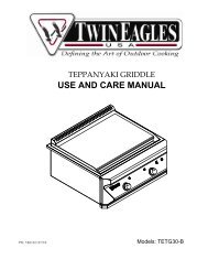
FIREPLACE DIMENSIONSJGCIKBADGAS LINEOPENINGEJUNCTION BOXASSEMBLYGAS LINEOPENINGVFD26 Series DimensionsIndex LetterABCDEGIJKDimension30 1/4"768mm30"762mm13 1/8"333mm18 1/8"460mm26"660mm25"635mm36 1/4"921mm36 1/4"921mm51 1/4"1302mmFigure 430816-1-0912 Page 7
SPECIFICATIONSModel VFD26F(M,P)(3,7) VFD26F(M,P)2 VFD26FP(3,7)0L10Input Maximum 20,000 20,000 10,000Minimum 14,000 14,000 N/ANATOrifice 2.10 mm (P-288) #49 (.073") P-265 #53 (.0595") P-214Air Shutter Opening 1/8" 1/8" 1/8"LPOrifice #55 (.052") P-182 #55 (.052") P-182 #64 (.036") P-193Air Shutter Opening 1/4" 1/4" 1/4"Fireplace DimensionsHeight 30 1/4" 30 1/4" 30 1/4"Depth 13 1/8" 13 1/8" 13 1/8"Front Width 30" 30" 30"Rear Width 25" 25" 25"Gas Inlet 3/8" 3/8" 3/8"AccessoriesFBBX Blower Extension Kit (MUST order FBB4)FBB4 Automatic Blower (MUST order FBBX)VPS26HP Bottom Trim KitVF2H26HP Hammered Pewter Hood KitVPF26HP Hammered Pewter Trim KitFPP26E Brick LinerVPL26HP Hammered Pewter Slat LouverAccessories for Millivolt VFD26F(M,P)(3,7) OnlyFRBC Battery Operated Remote ControlFRBTC Battery Operated Remote Control w/ThermostatFREC Electric Remote ControlFWS-1 Wall SwitchTMV Wall Thermostat, Millivolt - Reed SwitchTRW Wireless Remote Wall ThermostatWATER VAPOR: A BY-PRODUCT OF UNVENTED ROOM HEATERSWater vapor is a by-product of gas combustion. An unvented roomheater produces approximately one ounce (30ml) of water for every1,000 BTU's (.3KW's) of gas input per hour. .Unvented room heaters are recommended as supplemental heat (aroom) rather than a primary heat source (an entire house). In mostsupplemental heat applications, the water vapor does not create aproblem. In most applications, the water vapor enhances the lowhumidity atmosphere experienced during cold weather.The following steps will help insure that water vapor does notbecome a problem.1. Be sure the heater is sized properly for the application, includingample combustion air and circulation air.2. If high humidity is experienced, a dehumidifier may be used tohelp lower the water vapor content of the air.3. Do not use an unvented room heater as the primary heat source.Page 830816-1-0912
PROVISIONS FOR ADEQUATE COMBUSTION & VENTILATION AIRThis heater shall not be installed in a confined space or unusuallytight construction unless provisions are provided for adequatecombustion and ventilation air.A confined space is an area with volume less than 50 cubic feet per1,000 Btuh of the combined input rates of all appliances drawingcombustion air from that space. Small areas such as equipmentrooms are confined spaces. Furnaces installed in a confined spacewhich supply heated air to areas outside the space must draw returnair from outside the space through tightly sealed return air ducts. Aconfined space must have 2 openings into the space for combustionair. One opening must be within 12 inches of the ceiling andthe other must be within 12 inches of the floor. The required sizingof these openings is determined by whether inside or outside air isused to support combustion, the method by which the air is broughtto the space (vertical or horizontal duct) and by the total input rateof all appliances in the space.Unusually Tight ConstructionThe air that leaks around doors and windows may provide enoughfresh air for combustion and ventilation. However, in buildings ofunusually tight construction, you must provide additional fresh air.Unusually tight construction is defined as constructionwhere:a. Walls and ceilings exposed to the outside atmosphere havea continuous water vapor retarder with a rating of one permor less with openings gasketed or sealed, andb. Weatherstripping has been added on openable windows anddoors, andc. Caulking or sealants are applied to areas such as jointsaround window and door frames, between sole plates andfloors, between wall-ceiling joints, between wall panels, atpenetrations for plumbing, electrical, and gas lines, and atother openings.If your home meets all of the three criteria above, you must provideadditional fresh air. See “Ventilation Air From Outdoors,” page10.Determining if You Have a Confined or Unconfined SpaceUse this worksheet to determine if you have a confined or unconfinedspace.Space: Includes the room in which you will install heater plus anyadjoining rooms with doorless passageways or ventilation grillsbetween the rooms.1. Determine the volume of the space (length x width x height).Length x Width x Height =cu. ft. (volume ofspace)Example: Space size 16 ft. (length) x 10 ft. (width) x 8 ft. (ceilingheight) = 1,280 cu. ft. (volume of space)If additional ventilation to adjoining room is supplied with grillsor openings, add the volume of these rooms to the total volumeof the space.2. Divide the space volume by 50 cubic feet to determine themaximum BTU/Hr the space can support.(volume of space) ÷ 50 cu. ft. = (maximumBTU/Hr the space can support)Example: 1,280 cu. ft. (volume of space) ÷ 50 cu. ft. = 25.6 or25,600 (maximum BTU/Hr the space can support)3. Add the BTU/Hr of all fuel burning appliances in the space.Vent-free heaterBTU/HrGas water heaterBTU/HrGas furnaceBTU/HrVented gas heaterBTU/HrGas fireplace logsBTU/HrOther gas appliances* +BTU/HrTotal = BTU/HrExample: Vented gas heater 20,000 BTU/HrVent-free heater + 18,000 BTU/HrTotal = 38,000 BTU/Hr*Do not include direct-vent gas appliances. Direct vent drawscombustion air from the outdoors and vents to the outdoors.4. Compare the maximum BTU/Hr the space can support with theactual amount of BTU/Hr used.BTU/Hr (maximum the space can support)BTU/Hr (actual amount of BTU/Hr used)Example:25,600 BTU/Hr (maximum the space can support)38,000 BTU/Hr (actual amount of BTU/Hr used)WARNINGIf the area in which the heater may be operated is smaller than thatdefined as an unconfined space or if the building is of unusuallytight construction, provide adequate combustion and ventilationair by one of the methods described in the National Fuel GasCode, ANSI Z223.1/NFPA 54, Air for Combustion and Ventilation,or applicable local codes.The space in the above example is a confined space because theactual BTU/Hr used is more than the maximum BTU/HR the spacecan support. You must provide additional fresh air. Your optionsare as follows:A. Rework worksheet, adding the space of an adjoining room. Ifthe extra space provides an unconfined space, remove doorto adjoining room or add ventilation grills between rooms. SeeVentilation Air From Inside Building.B. Vent room directly to the outdoors. See Ventilation Air FromOutdoors.C. Install a lower BTU/Hr heater, if lower BTU/Hr size makes roomunconfined.If the actual BTU/Hr used is less than the maximum BTU/Hr thespace can support, the space is an unconfined space. You will needno additional fresh air ventilation.WARNINGYou must provide additional ventilation air in a confinedspace.30816-1-0912 Page 9
PROVISIONS FOR ADEQUATE COMBUSTION & VENTILATION AIRVentilation AirVentilation Air From Inside BuildingThis fresh air would come from an adjoining unconfined space. Whenventilating to an adjoining unconfined space, you must provide twopermanent openings: one within 12" of the ceiling and one within12" of the floor on the wall connecting the two spaces (see options1 and 2, Figure 5). You can also remove door into adjoining room(see option 3, Figure 5). Each ventilation grill or opening shall havea minimum free area of one square inch per 1,000 BTU/HR of thetotal input rating of the gas equipment in the confined space.Ventilation Air From OutdoorsProvide extra fresh air by using ventilation grills or ducts. You mustprovide two permanent openings: one within 12" of the ceiling andone with 12" of the floor. Connect these items directly to the outdoorsor spaces open to the outdoors. These spaces include attics andcrawl spaces. In most cases for direct communication with theoutdoors or direct communication through a vertical duct a freearea opening of one square inch per 4,000 BTU/HR of heater inputrating for each grill. If a horizontal duct is used, a grill free area orduct opening shall have a free area opening of one square inch per2,000 BTU/HR for each grill. Follow the National Fuel Code, ANSIZ223.1/NFPA 54, Air for Combustion and Ventilation, or applicablelocal codes, for required size of ventilation grills or ducts.IMPORTANT: Do not provide openings for inlet or outlet air into atticif attic has a thermostat-controlled power vent. Heated air enteringthe attic will activate the power vent.Figure 5WARNINGRework worksheet, adding the space of the adjoiningunconfined space. The combined spaces must have enoughfresh air to supply all appliances in both spaces.Figure 6CONNECTING THE GASThe inlet connection is located on the right side of the gas valve.Attach gas inlet line to gas valve.If installing the an Optional Blower, it must be installed beforeconnecting the gas line.Page 1030816-1-0912
GAS SUPPLYCheck all local codes for requirements, especially for the size andtype of gas supply line required.Pipe Length0-10 feet0-3 meters10-40 feet4-12 meters40-100 feet13-30 meters100-150 feet31-46 metersRecommended Gas Pipe DiameterSchedule 40 PipeInside DiameterTubing, Type LOutside DiameterNat. L.P. Nat. L.P.1/2”12.7mm1/2”12.7mm1/2”12.7mm3/4”19mm3/8”9.5mm1/2”12.7mm1/2”12.7mm1/2”12.7mm1/2”12.7mm5/8”15.9mm3/4”19mm7/8”22.2mm3/8”9.5mm1/2”12.7mm1/2”12.7mm3/4”19mmPressure Testing of the Gas Supply System1. To check the inlet pressure to the gas valve, a 1/8" (3mm) N.P.T.plugged tapping, accessible for test gauge connection, mustbe placed immediately upstream of the gas supply connectionto the appliance.2. The appliance and its individual shutoff valve must bedisconnected from the gas supply piping system during anypressure testing of that system at test pressures in excess of1/2 psig (3.5 kPa).3. The appliance must be isolated from the gas supply pipingsystem by closing its individual manual shutoff valve duringany pressure testing of the gas supply piping system at testpressures equal to or less than 1/2 psig (3.5 kPa).NOTICE: Never use plastic pipe. Check to confirm whether yourlocal codes allow copper tubing or galvanized.NOTICE: Since some municipalities have additional local codes, it isalways best to consult your local authority and installation code.Installing a New Main Gas CockEach appliance should have its own manual gas cock.A manual main gas cock should be located in the vicinity of the unit.Where none exists, or where its size or location is not adequate,contact your local authorized installer for installation or relocation.Compounds used on threaded joints of gas piping shall be resistantto the action of liquefied petroleum gases. The gas lines must bechecked for leaks by the installer. This should be done with a soapsolution watching for bubbles on all exposed connections, and ifunexposed, a pressure test should be made.WARNINGNever use an exposed flame to check for leaks. Appliancemust be disconnected from piping at inlet of control valve andpipe capped or plugged for pressure test. Never pressure testwith appliance connected; control valve will sustain damage!A gas valve and ground joint union should be installed in the gasline upstream of the gas control to aid in servicing. It is required bythe National Fuel Gas Code that a drip line be installed near the gasinlet. This should consist of a vertical length of pipe tee connectedinto the gas line that is capped on the bottom in which condensationand foreign particles may collect.The use of the following gas connectors is recommended:— ANS Z21.24 Appliance Connectors of Corrugated Metal Tubingand Fittings— ANS Z21.45 Assembled Flexible Appliance Connectors of OtherThan All-Metal ConstructionThe above connectors may be used if acceptable by the authorityhaving jurisdiction. The state of Massachusetts requires that a flexibleappliance connector cannot exceed three feet in length.Figure 7WARNINGIf one of the above procedures results in pressures in excess of1/2 psig (14" w.c.) (3.5 kPa) on the appliance gas valve, it willresult in a hazardous condition.Checking Manifold Pressure3 Series Millivolt Natural gas will have a manifold pressure ofapproximately 3.5" w.c. (.871kPa) for maximum input or 1.7" w.c.(.423kPa) for minimum input at the pressure regulator outlet withthe inlet pressure to the pressure regulator from a minimum of 5.0"w.c. (1.120kPa) for the purpose of input adjustment to a maximumof 10.5" w.c. (2.614kPa).2 Series Hydraulic Thermostat Natural gas will have a manifoldpressure of approximately 6.0" w.c. (1.49kPa) at the pressureregulator outlet with the inlet pressure to the pressure regulatorfrom a minimum of 7.0" w.c. (1.74kPa) for the purpose of inputadjustment to a maximum of 10.5" w.c. (2.615kPa).3 Series Millivolt Propane gas will have a manifold pressureapproximately 10.0"w.c. (2.49kPa) for maximum input or6.3"w.c. (1.568kPa) for minimum input at the pressure regulatoroutlet with the inlet pressure to the pressure regulator froma minimum of 11.0"w.c. (2.739kPa) for the purpose of inputadjustment to a maximum of 13.0"w.c. (3.237kPa).2 Series Hydraulic Thermostat Propane gas will have a manifoldpressure approximately 10.0"w.c. (2.49kPa) at the pressure regulatoroutlet with the inlet pressure to the pressure regulator from a minimumof 11.0"w.c. (2.739kPa) for the purpose of input adjustment to amaximum of 13.0"w.c. (3.237kPa).30816-1-0912 Page 11
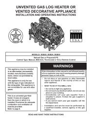
CLEARANCESMinimum Wall and Ceiling ClearancesMantel Clearances for Built-in Installation36”(91.44 cm)2” (5.08 cm)MANTEL12”(30.5cm)10”11”(25.4cm)(27.9cm)8”10 1/4”(20.3cm)(26.0cm)6”9½”(15.2cm)(24.1cm)8 3/4”(22.2cm)5½”(14.0cm)4 3/4”(12.1cm)TOP OF FRAME 04”(10.2cm)2½”(63.0cm)COMBUSTIBLESALLOWEDFigure 8This fireplace can be installed with zero (0") clearance tocombustible material.When facing the front of the appliance the minimum clearances tocombustible construction (material) are the following:1. Clearances from the right side or left side of the fireplace openingto any combustible wall or material should not be less than 2inches.2. Clearances from the top of the fireplace opening to the ceilingshould not be less than 36 inches.Figure 9COMBUSTIBLE MATERIALDo not attach combustible material to the mantel of your fireplace.This is a fire hazard.No greeting cards, stockings or ornamentation of any type should beplaced on or attached to the fireplace. This is a heating appliance.The flow of heat can ignite combustibles.HEATFLOWFigure 10Figure 11Page 1230816-1-0912
INSTALLATION OF FIREPLACE AND MANTEL1. Remove fireplace from carton.2. Remove mantel top and front base from mantel assembly.6. Place back base and fireplace in desired location.7. Connect gas line and electrical wiring at this time in accordancewith local codes.ELECTRICALCONNECTIONOPENINGGAS LINECONNECTIONOPENING3. Remove screw attached to fireplace top and through"L Bracket" attached to back of breast board.8. Place mantel assembly around fireplace and center. Replacethe screw removed in step 3 to secure fireplace to mantelassembly.4. Remove mantel assembly from fireplace.5. Remove shrink wrap and logs from fireplace.30816-1-0912 Page 13
INSTALLATION OF FIREPLACE AND MANTEL9. Attach mantel assembly to studs in the wall through the"back brace" using two 3" drywall screws provided.11. Place mantel top onto mantel assembly.10. Slide front base under front of mantel assembly.12. Install outer trim. See Page 15.13. Install fiber logs per the Log Placement Instructions. SeePage 16.14. Install hood. See Page 15.Page 1430816-1-0912
OUTER TRIM INSTRUCTIONS1. Remove upper louver, grasp louver at left and right ends; lift and pull forward.2. Open bottom louver, then lift to remove.3. Install the right frame and left frame to the fireplace. Align clearance holes in frame with screw holes in fireplace. Attach right frameand left frame to fireplace. Use two 8 x 1/2” Phillips screws for each frame.4. Insert top frame into interior, top of fireplace. Align clearance holes in top frame with screw holes in fireplace. Attach top frame tofireplace. Use two 8 x 1/2” Phillips screws for top frame.5. Replace bottom louver.6. Replace top louver.3-PIECE FRAME KITSIDE TRIMHOOD INSTRUCTIONS1. Remove upper louver, grasp louver at left and right ends; lift and pull forward.2. Remove screen frame assembly.3. Outer trim must be installed before installing hood.4. Place the top hood flange on top of the firebox, then install one screw (A) at the center on vent free fireplace through the firebox topfrom below.5. Install one screw (B) at each end of the hood as shown.6. Replace upper louver.7. Replace screen frame assembly.CAUTIONA hood must be installed prior to operation of appliance.30816-1-0912 Page 15
LOG PLACEMENT1. Place front logs (#1 and #2) between front grate flange andmain burner. Align notches on front logs with locator tabs inbase.2. Place middle log (#3) between front and rear loop of burner.NOTICE: Do not place log on top of pilot assembly.3. Place rear log (#4) on rear log shelf. Bottom flange of log mustbe placed between the log shelf and burner tube.4. This step is optional for VFD26FP3L10 log sets. Place fronttwig (#5) onto (#1) log and flat area on (#3) log. The bottomof the front twig is to be placed behind the grate tang that issecond from the left.Attention: Do not use Figures 12 and 13 to order logs. Refer toPages 34 to 35, Parts list and Page 36, Parts View to order logs.Refer to Figure 12 for the following warning.CAUTIONFailure to position the parts in accordance with this diagram orfailure to use only parts specifically approved with this heatermay result in property damage or personal injury.Figure 125432Figure 131Page 1630816-1-0912
PLACEMENT OF GLOWING EMBERS (ROCK WOOL)Provided with the log set is a small bag of glowing embers (rockwool) to be placed between logs on the flat metal surface of theburner.Placement of the embers (rock wool) is very individual and lightcoverage of the areas indicated will provide your best effects. Werecommend separation of the rock wool by hand and make yourcoverage as light and fluffy as possible.Place just enough embers (rock wool) on the burner to obtain theglow and a gold yellow flame.Do not place rock wool over large ports in rear portion of burner.A thin layer of rock wool should be placed under open spacebetween the front and middle logs.Rock wool should not be placed in the area of the pilot assembly.Glowing embers (rock wool) can cover the burner in betweenthe front and middle logs, but very little is necessary to cover thisarea. Excess ember material causes the yellow flame to becomeorange and stringy. Apply just enough to obtain slow glow and agold, yellow flame.Replacement of loose material (glowing embers) must be purchasedfrom Empire Comfort Systems, Inc. Application of excess loosematerial (glowing embers) may adversely affect performance ofthe heater.WARNINGAll previously applied loose material must be removed prior toreapplication.Refer to Parts List, Pages 34 to 35 to order loose material (rockwool).NOTICE: A single layer of embers is to be used when applyingPlatinum Bright Embers (alone or in combination with productionembers) to the burner.Replacement Loose Material(glowing embers)Rock Wool 15998Platinum Bright EmbersPart NumberPE-20-1Figure 1430816-1-0912 Page 17
OPERATION INSTRUCTIONS/FLAME APPEARANCEFlames from the pilot (rear right back side of the burner) as wellas the main flame should be visually checked as the log set isinstalled.In normal operation at full rate after 10 to 15 minutes, the flameappearance should be sets of yellow flames.NOTICE: All flames will be random by design, flame height will goup and down.Avoid any drafts that alter burner flame patterns. Do not allow fans toblow directly into fireplace. Do not place a blower inside the burnerarea of the firebox. Ceiling fans may create drafts that alter flamepatterns. Sooting and improper burning will result.During manufacturing, fabricating and shipping, various componentsof this appliance are treated with certain oils, films or bonding agents.These chemicals are not harmful, but may produce annoying smokeand smells as they are burned off during the initial operation of theappliance, possibly causing headaches or eye or lung irritation. Thisis a normal and temporary occurrence.The initial break-in operation should last 2-3 hours with the burnerat the highest setting. Provide maximum ventilation by openingwindows or doors to allow odors to dissipate. Any odors remainingafter this initial break-in will be slight and will disappear withcontinued use.PERIODIC CLEANING – Refer to parts diagram for location ofitems discussed below.• Do not use cleaning fluid to clean logs or any part of heater.• Logs - brush with soft bristle brush or vacuum with brushattachment.• Remove loose particles and dust from the burner areas,controls, piezo covers and grate.• Inspect and clean burner air intake hole. Remove lint or particleswith brush. Failure to keep air intake hole clean will result insooting and poor combustion.ANNUAL CLEANING/INSPECTION – Refer to parts diagram forlocation of items discussed below.• Inspect and clean burner air intake hole. Remove lint or particleswith vacuum or brush. Failure to keep air intake hole clean willresult in sooting and poor combustion.• Inspect and clean all burner ports.• Inspect ODS pilot for operation and accumulation of lint at airintake holes.• Verify flame pattern and log placement for proper operation.• Verify smooth and responsive ignition of main burner.MAINTENANCEKeep the control compartment, logs and burner area surroundingthe logs clean by vacuuming or brushing area at least twice a year.WARNINGTHE LOGS CAN GET VERY HOT – HANDLE ONLY WHENCOOL.Always turn off gas to the pilot before cleaning. For relighting, referto lighting instructions located on the rating plate of the log set.Never obstruct the flow of the combustion and ventilation air. Keepthe front of the fireplace clear of all obstacles and materials.Leave at least 36" clearance from the front of the fireplace.Screen should be closed during operation.Page 1830816-1-0912
10,000 BTU MILLIVOLT LIGHTING INSTRUCTIONSFOR YOUR SAFETY READ BEFORE LIGHTINGWarning: If you do not follow these instructions exactly, a fire or explosion mayresult, causing property damage, personal injury or loss of life.A. This appliance has a pilot which must be lighted byhand. When lighting the pilot, follow these instructionsexactly.B. BEFORE LIGHTING, smell all around the appliance areafor gas. Be sure to smell next to the floor because somegas is heavier than air and will settle on the floor.WHAT TO DO IF YOU SMELL GAS• Do not try to light any appliance• Do not touch any electrical switch; Do not use anyphone in your building• Immediately call your gas supplier from a neighbor'sphone. Follow the gas supplier's instructions.• If you cannot reach your gas supplier, call the firedepartment.C. Use only your hand to push in or turn the gas controlknob. Never use tools. If the knob will not push in orturn by hand, don't try to repair it, call a qualified servicetechnician. Force or attempted repair may result in a fireor explosion.D. Do not use this appliance if any part has been under water.Immediately call a qualified service technician to inspectthe appliance and to replace any part of the control systemand any gas control which has been under water.LIGHTING INSTRUCTIONS1. STOP! Read the safety information above on this page.2. Open bottom louver assembly (if applicable).3. Set REMOTE/OFF/ON switch to"OFF".4. Turn off all electric power to theappliance (if applicable).5. Push in gas control knob slightlyand turn clockwise to "OFF".NOTE: Knob cannot be turned from "PILOT"to "OFF" unless knob is pushed in slightly.Do not force.OFF6. Wait ten minutes to clear out any gas. Thensmell for gas, including near thefloor. If you smell gas, STOP! Follow"B" in the safety informationabove. If you do not smell gas, goto the next step.ON ONPILOT7. Find pilot - Follow metal tube fromgas control. The pilot is locatedTHERMOCOUPLE(LPG)next to the burner, near the rightTHERMOCOUPLEside.(NATURAL)GAS CONTROL KNOBSHOWNIN IN "OFF" POSITION.REMOTETHERMOPILEELECTRODE8. Turn gas control knob counterclockwiseto "PILOT".9. Push in control knob all the way and hold in. Repeatedly pushthe Piezo Ignitor Button until the pilot is lit. Continue to holdthe control knob in for about one minute after the pilot is lit.Release knob, and it will pop back up. Pilot should remain lit.If it goes out, repeat steps 5 through 9.• If knob does not pop up when released, STOP and IM-MEDIATELY call a qualified service technician or gassupplier.• If the pilot will not stay lit after several tries, turn the gascontrol knob to "OFF" and call your service technician orgas supplier.10. Turn gas control knob counterclockwise to "ON".11. Set REMOTE/OFF/ON switch to desired setting.12. Turn on all electric power to the appliance (if applicable).13. Close bottom louver assembly (if applicable).TO TURN OFF GAS TO APPLIANCE1. Open bottom louver assembly (if applicable).2. Set REMOTE/OFF/ON switch to "OFF."3. Turn off all electric power to the appliance if service is to beperformed (if applicable).4. Push in gas control knob slightly and turn clockwiseto "OFF". Do not force.5. Close bottom louver assembly (if applicable).30816-1-0912 Page 19
MILLIVOLT LIGHTING INSTRUCTIONSFOR YOUR SAFETY READ BEFORE LIGHTINGWarning: If you do not follow these instructions exactly, a fire or explosion mayresult, causing property damage, personal injury or loss of life.A. This appliance has a pilot which must be lighted byhand. When lighting the pilot, follow these instructionsexactly.B. BEFORE LIGHTING, smell all around the appliance areafor gas. Be sure to smell next to the floor because somegas is heavier than air and will settle on the floor.WHAT TO DO IF YOU SMELL GAS• Do not try to light any appliance• Do not touch any electrical switch; Do not use anyphone in your building• Immediately call your gas supplier from a neighbor'sphone. Follow the gas supplier's instructions.• If you cannot reach your gas supplier, call the firedepartment.C. Use only your hand to push in or turn the gas controlknob. Never use tools. If the knob will not push in orturn by hand, don't try to repair it, call a qualified servicetechnician. Force or attempted repair may result in a fireor explosion.D. Do not use this appliance if any part has been under water.Immediately call a qualified service technician to inspectthe appliance and to replace any part of the control systemand any gas control which has been under water.LIGHTING INSTRUCTIONS1. STOP! Read the safety information above on this page.2. Open bottom louver assembly (if applicable).3. Set REMOTE/OFF/ON switch to"OFF".4. Turn off all electric power to theappliance (if applicable).5. Push in gas control knob slightlyand turn clockwiseto"OFF".NOTE: Knob cannot be turned from "PILOT"to "OFF" unless knob is pushed in slightly.OFFOFFDo not force.ON ON ON6. Wait ten minutes to clear out anygas. Then smell for gas, includingPILOTnear the floor. If you smell gas,STOP! Follow "B" in the safetyinformation above. If you do notsmell gas, go to the next step.7. Find pilot - Follow metal tube fromTHERMOCOUPLE(LPG)gas control. The pilot is locatedTHERMOCOUPLEnext to the burner, near the right(NATURAL)side.GAS GASCONTROL KNOBKNOBSHOWN SHOWNIN IN IN "OFF" "OFF" POSITION.POSITION.REMOTETHERMOPILEELECTRODE8. Turn gas control knob counterclockwiseto "PILOT".9. Push in control knob all the way and hold in. Repeatedly pushthe Piezo Ignitor Button until the pilot is lit. Continue to holdthe control knob in for about one minute after the pilot is lit.Release knob, and it will pop back up. Pilot should remain lit.If it goes out, repeat steps 5 through 9.• If knob does not pop up when released, STOP and IM-MEDIATELY call a qualified service technician or gassupplier.• If the pilot will not stay lit after several tries, turn the gascontrol knob to "OFF" and call your service technician orgas supplier.10. Turn gas control knob counterclockwise to "ON".11. Set REMOTE/OFF/ON switch to desired setting.12. Turn on all electric power to the appliance (if applicable).13. Close bottom louver assembly (if applicable).TO TURN OFF GAS TO APPLIANCE1. Open bottom louver assembly (if applicable).2. Set REMOTE/OFF/ON switch to "OFF."3. Turn off all electric power to the appliance if service is to beperformed (if applicable).4. Push in gas control knob slightly and turn clockwiseto "OFF". Do not force.5. Close bottom louver assembly (if applicable).Page 2030816-1-0912
INTERMITTENT PILOT LIGHTING INSTRUCTIONSFOR YOUR SAFETY READ BEFORE LIGHTINGWarning: If you do not follow these instructions exactly, a fire or explosion may result,causing property damage, personal injury or loss of life.A. This appliance has a pilot which can be lighted with the manualon/off switch, a remote control, or by switching the receiverswitch to the “ON” position. When lighting the pilot, follow theseinstructions exactly.B. Before lighting smell all around the appliance area for gas. Besure to smell next to the floor because some gas is heavierthan air and will settle on the floor.What To Do If You Smell Gas• Do not try to light any appliance.• Do not touch any electrical switch;• Do not use any phone in your building.• Immediately call your gas supplier from a neighbor's phone.Follow the gas supplier's instructions.• If you cannot reach your gas supplier, call the fire department.Lighting InstructionsC. Use only your hand to push in or turn the gas control knob.Never use tools. If the knob will not push in or turn by hand,don't try to repair it; call a qualified service technician. Forceor attempted repair may result in a fire or explosion.D. Do not use this appliance if any part has been under water.Immediately call a qualified service technician to inspect theappliance and to replace any part of the control system andany gas control which has been under water.1. STOP! Read the safety information above.2. Turn OFF electric power to the appliance.3. Remove front surround panel assembly or bottom louver ifincluded.4. Turn gas cock counterclockwise to “On” position.5. Wait ten minutes to clear out any gas. Then smell for gas,including near the floor. If you smell gas, STOP! Follow “B” inthe safety information above on this page. If you do not smellgas, go to the next step.6. Turn ON electric power to the appliance.7. Find pilot - Follow metal tube from gas control. The pilot isbehind the burner on the right side.8. Turn main flame to on. If the pilot does not light within 60seconds, stop and go to Step 5.9. Refer to remote control instructions for detailed information,control features, and operation. Note: There is a CPI/IPI switchbehind the right side panel that allows for a continuous standingpilot mode or an intermittent pilot mode. See appliance manualfor location of this switch. If the pilot or burner does not staylit (in the standing pilot mode), stop and immediately call aqualified service technician or gas supplier.10. If the burner or pilot does not operate properly after severaltries, turn the gas cock clockwise to “OFF” and callyour service technician or gas supplier.11. Replace the front surround assembly or close bottom louverassembly.12. Operation of the gas valve is controlled by a manual on/off switch or a hand held remote control. Refer to remoteinstructions for detailed operation information.FLAMESENSORPILOTELECTRODEGAS COCKTo Turn Off Gas To Fireplace1. Set REMOTE/OFF/ON switch to OFF.2. Turn off all electric power to the appliance if service is to beperformed (if applicable).3. Lower bottom louver assembly.OFFON4. Push in gas control knob slightly and turn clockwiseto "OFF." Do not force.5. Close bottom louver assembly.30816-1-0912 Page 21
HYDRAULIC THERMOSTAT LIGHTING INSTRUCTIONSFOR YOUR SAFETY READ BEFORE LIGHTINGWarning: If you do not follow these instructions exactly, a fire or explosion mayresult, causing property damage, personal injury or loss of life.A. This appliance has a pilot which must be lighted byhand. When lighting the pilot, follow these instructionsexactly.B. Before lighting smell all around the appliance areafor gas. Be sure to smell next to the floor because somegas is heavier than air and will settle on the floor.What To Do If You Smell Gas• Do not try to light any appliance.• Do not touch any electrical switch;Do not use any phone in your building.• Immediately call your gas supplier from a neighbor'sphone. Follow the gas supplier's instructions.• If you cannot reach your gas supplier, call the firedepartment.C. Use only your hand to push in or turn the gas controlknob. Never use tools. If the knob will not push inor turn by hand, don't try to repair it; call a qualifiedservice technician. Force or attempted repair mayresult in a fire or explosion.D. Do not use this appliance if any part has been underwater. Immediately call a qualified service technicianto inspect the appliance and to replace any part of thecontrol system and any gas control which has beenunder water.1. Stop! Read the safety information above.2. Set thermostat (gas control knob) to lowest setting.3. Turn off all electric power to the appliance (if applicable).4. Push in gas control knob slightly and turn clockwiseto "OFF". Do not force.Lighting InstructionsPIEZO IGNITOR5. Wait ten minutes to clear out any gas. Then smell for gas,including near the floor. If you smell gas, STOP! Follow "B"in the safety information above. If you don't smell gas, goto the next step.6. Find pilot - Follow metal tube from gas control. The pilot islocated next to the burner, near the right side.7. Turn gas control knob counterclockwise to"PILOT."8. Push in gas control knob all the way and hold in. Repeatedlypush the piezo ignitor button until pilot is lit (or usea match to light pilot). Continue to hold the control knobin for about one minute after the pilot is lit. Release knoband it will pop back up. Pilot should remain lit. If it goesout, repeat steps 4 through 8.• If knob does not pop up when released, stop andimmediately call your service technician or gas supplier.• If the pilot will not stay lit after several tries, turn thegas control knob to "OFF" and call your service technicianor gas supplier.9. Turn gas control knob counterclockwise to "HI"(5).10. Turn on all electric power to appliance (if applicable).11. Set thermostat (gas control knob) to desired setting from"HI" (5) to "LO" (1).To Turn Off Gas To Appliance1. Set thermostat (gas control knob) to lowest setting.2. Turn off all electric power to appliance if service is tobe performed (if applicable).3. Push in gas control knob slightly and turn clockwiseto "OFF". Do not force.Page 2230816-1-0912
PILOT FLAME CHARACTERISTICSFigures 15, 17 and 19 show a correct pilot flame pattern. The correctflame will be blue and will extend beyond the thermocouple. Theflame will surround the thermocouple just below the tip. A slightyellow flame may occur where the pilot flame and main burnerflame meet. Figures 16, 18 and 20 show an incorrect pilot flamepattern. The incorrect pilot flame is not touching the thermocouple.This will cause the thermocouple to cool. When the thermocouplecools, the heater will shut down.MILLIVOLT PilotHYDRAULIC THERMOSTAT PilotCorrect Pilot Flame PatternFigure 17Correct Pilot Flame PatternFigure 15Incorrect Pilot Flame PatternFigure 18If pilot flame pattern is incorrect, as shown in Figure 18• See Troubleshooting, page 26.Incorrect Pilot Flame PatternFigure 16If pilot flame pattern is incorrect, as shown in Figure 16• See Troubleshooting, page 26.30816-1-0912 Page 23
PILOT FLAME CHARACTERISTICSINTERMITTENT PilotCorrect Pilot Flame PatternSENSORIGNITORCleaning and Pilot MaintenanceOxygen Depletion Sensor PilotWhen the pilot has a large yellow tip flame, clean the OxygenDepletion Sensor as follows:1. Clean the ODS pilot by loosening nut B from the pilot tubing.When this procedure is required, grasp nut A with an open endwrench.2. Blow air pressure through the holes indicated by the arrows.This will blow out foreign materials such as dust, lint and spiderwebs. Tighten nut B also by grasping nut A.PILOTBAMillivolt PilotFigure 21Figure 19BAIncorrect Pilot Flame PatternSENSORIGNITORHydraulic Thermostat PilotFigure 22PILOTBAIntermittant PilotFigure 23Figure 20If pilot flame pattern is incorrect, as shown in Figure 20:• See Troubleshooting, page 30-31.WARNINGNever use needles, wires, or similar cylindrical objects toclean the pilot to avoid damaging the calibrated ruby thatcontrols the gas flow.Page 2430816-1-0912
MAIN BURNER AND THERMOSTAT OPERATIONThe VFD26F(M,P)(3,7) gas control maximum and minimuminputs are listed below.OFF is the OFF position.PILOT is the PILOT position.VFD26F(M,P)(3,7)Max. 20,000 BTU/HRMin. 14,000 BTU/HRVFD26FP3L10 and VFD26FP(30,70)L10Max. 10,000Min. N/AVFD26F(M,P)2 Main Burner OperationThe gas control modulates from a minimum input of 14,000 BTU/HR ("LO" (1) setting) to a maximum input of 20,000 BTU/HR ("HI"(5) setting).Cleaning and Maintenance / Main BurnerWARNINGTurn off heater and let cool before cleaning.CAUTIONYou must keep control areas, burner and circulating airpassageways of heater clean. Inspect these areas of heaterbefore each use. Have heater inspected yearly by a qualifiedservice person. Heater may need more frequent cleaning due toexcessive lint from carpeting, bedding materials, etc.LogsBe careful cleaning and handling logs so as not to damage them.If logs break or fall apart in handling, spray the broken pieces andfibers with water, sweep up and discard.30816-1-0912 Page 25
MILLIVOLT WIRINGLabel all wires prior to disconnection when servicing controls. Wiringerrors can cause improper and dangerous operation. Verify properoperation after servicing.Millivolt thermopile is self powered, gas valve does not require 110volts. Maximum length of 20 feet of 16 AWG to conductor wires isto be used with all optional components.Use the two leads (Green and Red wires) to attach optionalcomponents.Check 750 Millivolt System OperationMillivolt system and all individual components may be checked witha millivolt meter 0-1000 MV range.Remote ReceiverUse the following steps to place the remote receiver adjacent tothe gas valve.Attention: The remote receiver bracket is not used in thisinstallation.WIRING DIAGRAM1. The remote receiver can not be placed behind the gas valveand burner assembly.2. When facing the appliance, the remote receiver must be placedto the right of the gas valve and burner assembly.NOTICE: Do not let remote control receiver come in contact withburner assembly.On circulating vent-free firebox, install remote control receiverbehind bottom louver.Refer to remote control installation and operating instructions formore details on remote control.HREMOTE CONTROL RECEIVER/THERMOSTAT/ CONTROLE EDISTANCE DU RECEPTEURN(OPTIONAL) THERMOSTAT(FACULATIVE) THERMOSTAT(OPTIONAL) WALL SWITCHINTERRUPTEUR MURAL(FACULTATIVE)REMOTE/OFF/ON SWITCHA DISTANCE/OUVERT/FERME INTERRUPTEURGAS VALVEVALVEDE GAZ(OPTIONAL) REMOTE CONTROL RECEIVER(FACULTATIVE) CONTROLE EDISTANCEDU RECEPTEURTHERMOPILEPILOTVEILLEUSEPage 26THERMOCOUPLE(NATURAL)THERMOCOUPLE(LPG)GAS VALVEREMOTE/OFF/ON SWITCHA DISTANCE/FERME/OUVERTINTERRUPTEURREMOTEOFFONFigure 24IF ANY OF THE ORIGINAL WIREAS SUPPLIED WITH THIS UNITMUST BE REPLACED, IT MUST BEREPLACED WITH NUMBER 18, 150°CWIRE OR ITS EQUIVALENT.SI UN DES FILS ELECTRIQUESORIGINAUX, VENANT DU FABRICANTAVEC CETTE UNITE, DOIT ETREREMPLACE, VOUS DEVEZ LEREMPLACER AVEC UN FILELECTRIQUE DE NUMERO 18,150 ° CDUL'EQUIVALENT.30816-1-0912
MILLIVOLT TROUBLESHOOTINGTurn appliance OFF and allow to cool before servicing. Only a qualified service person should service and repair the heater.1. When ignitor button is pressed, there is no spark at ODS/pilot.a. Ignitor electrode positioned wrong - Replace pilot.b. Ignitor electrode is broken - Replace pilot.c. Ignitor electrode not connected to ignitor cable - Reconnectignitor cable.d. Ignitor cable pinched or wet. Keep ignitor cable dry - Freeignitor cable if pinched by any metal or tubing.e. Broken ignitor cable - Replace ignitor cable.f. Bad piezo ignitor - Replace piezo ignitor.2. Appliance produces unwanted odors.a. Appliance burning vapors from paint, hair spray, glues, etc.- Ventilate room. Stop using odor causing products whileheater is running.b. Gas leak - Locate and correct all leaks.3. Appliance shuts off during use. (Pilot and main burner areoff.)a. Not enough fresh air is available for ODS/pilot to operate -Open window and/or door for ventilation.b. Low line pressure - Contact local gas company.c. ODS/pilot is partially clogged - Clean ODS/pilot.d. Defective thermocouple - Replace pilot.4. Appliance shuts off during use. (Pilot stays on.)a. Low line pressure - Check line pressure to the valve.b. Defective thermopile - Check pilot flame, check wire connections,output should be a minimum of 325 millivoltsacross. TH/TP and TP terminals with REMOTE/ON/OFFswitch off.5. Gas odor even when control knob is in OFF position.a. Gas leak - Locate and correct all leaks.b. Control valve defective - Replace control valve.6. When ignitor button is pressed, there is spark at ODS/pilot,but no ignition.a. Gas supply turned off or manual shutoff valve closed - Turnon gas supply or open manual shutoff valve.b. Control knob not in PILOT position - Turn control knob toPilot position.c. Control knob not pressed in while in PILOT position - Pressin control knob while in PILOT position.d. Air in gas lines when installed - Continue holding down controlknob. Repeat igniting operation until air is removed.e. ODS/pilot is clogged - Replace ODS/pilot assembly or getit serviced.f. Gas regulator setting is not correct - Replace gas regulator.7. ODS/pilot lights but flame goes out when control knob isreleased.a. Control knob not fully pressed in - Press in control knobfully.b. Control knob not pressed in long enough - After ODS/pilotlights, keep control knob pressed in 30 seconds.c. Manual Shutoff valve not fully open - Fully open manualshutoff valve.d. Thermocouple connection loose at control valve - Handtighten until snug, then tighten 1/4 turn more.e. Pilot flame not touching thermocouple, which allows thermocoupleto cool, causing pilot flame to go out. This problemcould be caused by either low gas pressure or dirty orpartially clogged ODS/pilot - Contact local gas company.f. Thermocouple damaged - Replace thermocouple.g. Control valve damaged - Replace control valve.8. Burner does not light after ODS/pilot is lit.a. Burner orifice clogged - Clean burner or replace main burnerorifice.b. Burner orifice diameter is too small - Replace burner orifice.c. Inlet gas pressure is too low - Contact qualified serviceperson.9. If burning at main burner orifice occurs (a loud, roaringblow torch noise).a. You must turn off burner assembly and contact a qualifiedservice person.b. Manifold pressure is too low - Contact local gas company.c. Burner orifice clogged - Clean burner or replace burnerorifice.10. Logs appear to smoke after initial operation.a. Vapors from paint or curing process of logs - Problem willstop after a few hours of operation. Run the heater with thedamper open if you have one, or open a window for the firstfew hours.Log heater is intended to be smokeless. Turn OFF heaterand call qualified service person.11. Heater produces a whistling noise when main burner islit.a. Turning control knob to HIGH position when main burner iscold - Turn control knob to LOW position and let warm upfor a minute.b. Air in gas line - Operate burner until air is removed fromline. Have gas line checked by local gas company.c. Dirty or partially clogged burner orifice - Clean burner orreplace burner orifice.12. No gas to pilot.a. LP-regulator shut down due to inlet pressure too high -Verify LP tank regulator is installed and set at 11" to 13"w.c. Replace regulator on heater.If the gas quality is bad, your pilot may not stay lit, the burners may produce soot and the heater may backfire whenlit. If the gas quality is bad or pressure is low, contact your local gas supplier immediately.30816-1-0912 Page 27
IP ELECTRONIC SYSTEM OPERATING INSTRUCTIONSAttention: For shipping purposes, the Electronic ControlModule and Receiver Plate assembly is loosely packagednear the left side of the appliance. It is necessary that the receiverplate assembly be secured to the left front flange of theappliance at the time of installation. To secure, remove thetwo lower screws in the left side flange of the appliance, thenplace the receiver plate assembly over the left front flangeand secure with the two screws previously removed.5.25 VDC ELECTRONIC CONTROL VALVEThe electronic control valve system includes the ability to switchthe pilot from a standing pilot mode to an intermittent pilot mode.• IPI Mode - In the Intermittent Pilot mode, when the unit isturned ON, it will cause spark to the pilot, light the pilot,then allow the burner to light. When the unit is turned toOFF, both the burner and pilot will be OFF.• CPI Mode - In the Continuous Pilot mode, the pilot remainsON continuously even when the burner is turnedOFF.Note: A small toggle switch is located on the receiver plate (leftside of unit) that is used to switch from IPI (upward position) to theCPI (downward position). See Figure 25.When the unit is turned to ON, the electrical current will energizea spark to the pilot igniter. Once the pilot sensor heats up (after afew seconds), the valve will be energized, allowing gas to flow tothe burner.1. Follow the SAFETY and LIGHTING INSTRUCTIONS for IntermittentPilot controls found in this manual, and on labelsfound in the control compartment located in the lower cavityof the appliance.2. During the operating season (or in power outage periods), it isrecommended that the pilot remain in the CPI (standing pilotmode) to reduce cold start issues, and/or conserve batterybackup power during a power outage.3. The gas valve has inlet and outlet pressure taps as shown inFigure 25. Refer to page 11 for gas pressure requirements.Note:The gas control has a manual HI/LO flame adjustmentknob (regulator) that allows you to increase or decreasethe height of the burner flame. See Figure 25. Rotatethe HI/LO knob counterclockwise to “HI” to increase theflame height, and clockwise to “LO” to decrease the flameheight.OPTIONAL REMOTE CONTROLSOptional remote controls are available for use with this appliance.There is an area on the Receiver Plate (between the ElectronicControl module and the back-up battery pack) that the RemoteReceiver should be placed. A velcro pad is pre-attached to theplate assembly for quick attachment of the remote receiver.To connect the remote receiver to the appliance, first disconnectthe ON/OFF switch wires from the white and green wire connectorsand connect the wires from the remote receiver to the greenand white wire connectors. See Figure 25.Follow the instructions included with the remote control for programmingand other operational information.9 PIN CONNECTORDFCELECTRONICCONTROLMODULEGROUNDSPARK RODIGNITORSENSORPILOTSENSOROPTIONALREMOTECONTROLRECEIVERLOCATIONAA (4)BATTERYBACKUPIPICPIRECEIVER PLATEPILOT SELECTOR SWITCHIPI - INTERMITANT PILOT (UP)CPI - CONTINUOUS PILOT (DOWN)GAS VALVEPILOTASSEMBLYMANUALHI/LOREGULATOROUTLETPRESSURETAPINLETPRESSURETAPMANUAL ON/OFF OPERATIONAL SWITCHNOTE: ADDITIONAL ON/OFF SWITCH & WIRING INCLUDEDTO INSTALL SWITCH TO SIDE OF SURROUND PANEL.SEE PAGE 14.Figure 25Page 2830816-1-0912
(((IP ELECTRONIC SYSTEM WIRING DIAGRAMCPI/IPISWITCHWHITEBLUEBLUEWHITEORANGEGREENREMOTE RECEIVER(OPTIONAL)ORON/OFFSWITCHYELLOWPILOT+ ONREMOTE- OFFBLACKWHITEGAS CONTROLVALVEBLACKBLACKWHITE(GND)GREENBLACKAC/DCPOWER ADAPTORREDBATTERYBACK-UPBATTERY HOLDERBLACKREDELECTRONICCONTROL MODULEIf any of the original wire as supplied with this unit must be replaced, it must be replaced with equivalent gauge and temperaturerated wire.This appliance is only for use with the type of gas indicated on the rating plate and may be installed in an aftermarket, permanentlylocated, manufactured (mobile) home where not prohibited by local codes. This appliance is not convertible for use with other gases,unless a certified kit is used.CAUTION: Do not operate the appliance with panel(s) removed, cracked or broken. Replacement of the panel(s) should be done bya licensed or qualified service person.WARNING: Improper installation, adjustment, alteration, service or maintenance can cause property damage, personal injury or lossof life. Installation and service must be performed by a qualified installer, service agency or the gas supplier.30816-1-0912 Page 29
INTERMITTENT CONTROL SYSTEM TROUBLESHOOTINGBrief Description of the ComponentsThe gas valve is fitted with a manual HI/LO knob to allow for manualmodulation of the gas outlet pressure to the appliance burner.The Digital Fireplace Control (DFC) is an automatic gas ignitionsystem based on a single microcontroller core. This control managesall functions related to ignition, flame sensing and supervisionfor atmospheric applications.The DFC can be set to provide continuous or intermittent ignitioncontrol sequences and flame monitoring with safety shutdown incase of failure.The DFC is set up as a stand alone (AC powered system withbattery back up. See Lighting Instructions on page 20 and WiringDiagram on page 28.TroubleshootingBefore proceeding with the procedures in the following troubleshootingtable, verify that the power supply (AC/DC adapter) ispresent and that the batteries inside the receiver and/or optionalbattery pack are fresh and installed with correct polarity.Make sure all the connections between the wire harnesses andsystem components are proper and positive.Verify that the static inlet pressure meets the manufacturer’s recommendedinlet pressure. If necessary adjust the line pressureregulator.If the recommended actions for the following troubleshooting chartdo not help to address the problem consider replacing wiring harnesses.WARNING:Any actions performed on the gas valve must be performedin accordance with this instruction manual. Likewise, anyactions performed on the DFC or other system componentsmust be done in accordance with the individual componentinstructions.Replacement of components must be performed in accordancewith this instructions manual.Page 3030816-1-0912
INTERMITTENT CONTROL SYSTEM TROUBLESHOOTING1If the DFC giving signal lock out:The board should be unlocked toreinitiate a pilot flame ignition (forthe correct unlock sequence referto the DFC Use and InstallationInstructions).NOIs the DFC board inlock out?NO1. Verify the electrical connections’ integrity andmake sure they are in accordance with the relevantsystem wiring diagram. If necessary replace thewire harness.2. Replace the DFC board.YES1. Check the spark electrode positioning - adjustas necessary.Was observed sparkat the Pilot Hoodbefore the DFCboard locked out?NO2. Replace the pilot assembly.3. Verify the electrical connections’ integrity andmake sure they are in accordance with therelevant system wiring diagram. If necessaryreplace the wire harness.4. Replace the DFC board.YESYES1. Verify the electrical connections’ integrity andmake sure they are in accordance with therelevant system wiring diagram. If necessaryreplace the wire harness.2. If pilot flow adjuster screw is not sealed:Check if pilot flow adjust screw is set correctly inaccordance with the appliance manufacturerinstructions. If necessary correct it.3. Replace pilot tube or complete pilotassembly.4. Replace the pilot orifice with a new orifice ofcorrect size, and type, or replace the pilotassembly. Under all circumstances follow theappliance manufacturer’s service instructions.5. Remove the provided wiring harnesses fromEv1 of gas valve (red base), and verify voltage atignition between the Ev1 terminal and the groundconnection on teh valve body. If the voltage isgreater than 0 then Replace Valve. OtherwiseReplace DFC.Spark continueswhile the pilot is ON.YES1. Replace the pilot assembly.2. Replace the DFC board.NO230816-1-0912 Page 31
INTERMITTENT CONTROL SYSTEM TROUBLESHOOTING2Main burner lightswhen the pilot onlyshould light.YES1. Replace DFC board.2. Replace the gas valve.NOPilot holds the flame?.YESNO1. Verify the pilot flame fully engulfs the tip of the sense electrode. If not replace the pilotassembly.2. Replace the pilot assembly.3. Carefully clean the electrical connections of the sense cable, and the DFC board sensecable connection.4. Replace the sense cable, or the cable-sense electrode assembly, or the pilot assembly.5. Verify the pilot is properly grounded.6. Replace the pilot orifice with a new orifice of correct size, and type, or replace the pilotassembly.7. If pilot flow adjuster screw is not sealed, correct it.Main burner ignites?YESNO1. Verify the electrical connections’ integrity and make sure they are in accordance with therelevant system wiring diagram. If necessary replace the wire harness.2. Check if the optional remote transmitter is in “thermostat” or “on” mode and verifyt there is acall for heat (f using a thermostat remote). Adjust the setting for heat.3. Verify that the pilot hood is properly fitted and a pilot flame is directed to properly ignite themain appliance burner.4. Replace the main burner orifice with a new orifice of correct size and type, or replace thepilot assembly. Under all circumstances follow the service instructions.5. Remove the provided wiring harnesses from EV2 of gas valve (red base), and verify voltageat ignition between the EV1 terminal and the ground connection on the valve body.5.1 If the voltage is greater than 0 then Replace Valve.5.2 Or Replace DFC.6. Check the pressure at the outlet pressure test point out according to the manufacturer’sinstruction. If not in accordance, replace the gas valve.Main burner remainsONNO1. Verify the electrical connections’ integrity and make sure they are in accordance with therelevant system wiring diagram. If necessary replace the wire harness.2. Check the pressure at the outlet pressure test point out according the manufacturer’sinstruction. If not in accordance replace the gas valve.3. With the system in the OFF position, connect the voltmeter between the EV2 terminal(green base) on the valve, and the ground on the valve body.Turn the system ON, let pilot light, and observe the following voltage sequence: once the pilotflame is proved, the voltage on EV2 should spike to approx. 5 VdC for approx. 2 sec and thendrop to approx. 0.6 VdC continuously.3.1 If the sequence is respected, replace the gas valve.3.2 If the sequence is not respected, replace the DFC board.Main burnermodulatesproperly?1. Replace the main burner orifice with a new orifice of correct size (partial blockage possible).Verify that the main burner flame modulates. If it does not modulate replace the gas valve.2. Verify that the gas valve outlet pressure limits are in accordance with the manufacturerspecifications. If not replace the gas valve.FOR MANUAL HI/LO VERSION3. Verify the flame changes while rotating the HI/LO knob on the front of the gas valve. If thereis no change replace the gas valve.Page 3230816-1-0912
JUNCTION BOX WIRING INSTALLATION INSTRUCTIONSCAUTION: ALL WIRING SHOULD BE DONE BY A QUALIFIED ELECTRICIAN AND SHALL BE IN COMPLIANCE WITH ALL LO-CAL, CITY AND STATE BUILDING CODES. BEFORE MAKING THE ELECTRICAL CONNECTION, MAKE SURE THAT MAIN POWERSUPPLY IS DISCONNECTED. THE APPLIANCE, WHEN INSTALLED, MUST BE ELECTRICALLY GROUNDED IN ACCORDANCEWITH LOCAL CODES OR, IN THE ABSENCE OF LOCAL CODES, WITH THE NATIONAL ELECTRICAL CODE ANSI/NFPA 70 (LAT-EST EDITION).A factory installed junction box is located on the lower right side of the fireplace. Wiring must be fed to the junction box and attached tothe receptacle that is provided. Leave approximately 6" of wire in the junction box for connection.Attach black wire to hot side (brass screws) of the receptacle and white wire to opposite side (silver screws) of receptacle. The groundwire should be attached to the green (ground) screw.Install the receptacle into the junction box. Attach cover plate.Junction Box ConnectionsFigure 2630816-1-0912 Page 33
PARTS LISTINDEX NO. PART NO. DESCRIPTIONCOMMON PART NUMBERS1 10554 NAILING FLANGE2 17162 JUNCTION BOX ASSEMBLY3 23461 TRIM - TOP4 23462 TRIM – LEFT5 23463 TRIM – RIGHT6 23464 LOUVER ASSEMBLY – UPPER7 23465 LOUVER ASSEMBLY – LOWER8 23460 HOOD9 23470 SCREEN FRAME ASSEMBLY13 17235 BRACKET, LOG LOCATOR15 R7624 AIR SHUTTER17 R7572 JAMB NUT19 P212 FITTING, ORIFICENS R5668 IGNITOR WIRENS 15998 ROCK WOOLVFD26F(M,P)20L(N,P)10 R5170 PILOT ASSEMBLY (LPG)10 R5171 PILOT ASSEMBLY (NAT)11 21590 PILOT BRACKET (LPG)11 23106 PILOT BRACKET (NAT)12 23449 PILOT SHIELD14 R9022 BURNER TUBE16 P182 ORIFICE (LPG)16 P265 ORIFICE (NAT)18 23473 BURNER BASE PLATE ASSEMBLY20 R2423 CONNECTOR, MALE21 23477 VALVE (NAT)21 23487 VALVE (LPG)22 23475 TUBING ASSEMBLY - SUPPLY23 23476 TUBING ASSEMBLY27 P239 NIPPLE, 3/8 NPT X 1 ½28 R2479 REGULATOR (NAT)28 R2480 REGULATOR (LPG)29 R2708 IGNITOR, PIEZOINDEX NO. PART NO. DESCRIPTIONVFD26F(M,P)30L(N,P)10 R3623 PILOT ASSEMBLY (LPG)10 R3624 PILOT ASSEMBLY (NAT)11 21590 PILOT BRACKET (LPG)11 23106 PILOT BRACKET (NAT)12 23449 PILOT SHIELD14 R9022 BURNER TUBE16 P182 ORIFICE (LPG)16 P288 ORIFICE (NAT)18 23473 BURNER BASE PLATE ASSEMBLY20 R2423 CONNECTOR, MALE21 R3625 VALVE (LPG)21 R3626 VALVE (NAT)22 23493 TUBING ASSEMBLY - SUPPLY23 23492 TUBING ASSEMBLY (LPG)23 23496 TUBING ASSEMBLY (NAT)24 R7063 REGULATOR, NAT PILOT (NAT)25 23491 TUBING ASSEMBLY (NAT)26 23450 VALVE BRACKET29 R2708 IGNITOR, PIEZO30 R3436 SWITCH, REMOTE/OFF/ONNS R10947 WIRE ASSEMBLYVFD26F(M,P)30L10(N,P)10 R3623 PILOT ASSEMBLY (LPG)10 R3624 PILOT ASSEMBLY (NAT)11 21590 PILOT BRACKET (LPG)11 23106 PILOT BRACKET (NAT)12 23449 PILOT SHIELD14 27426 BURNER TUBE16 P214 ORIFICE (NAT)16 P193 ORIFICE (LPG)20 R2423 CONNECTOR, MALE21 R9368 VALVE (NAT)21 R9369 VALVE (LPG)22 23493 TUBING ASSEMBLY - SUPPLY23 23496 TUBING ASSEMBLY (LPG)23 23476 TUBING ASSEMBLY (NAT)24 27426 REGULATOR, NAT PILOT25 23491 TUBING ASSEMBLY (NAT)26 23450 VALVE BRACKET29 R2708 IGNITOR, PIEZO30 R3436 SWITCH, REMOTE/OFF/ONNS R10947 WIRE ASSEMBLYAttention: When ordering parts, it is very important that part number and description of part coincide.Page 3430816-1-0912
PARTS LISTINDEX NO. PART NO. DESCRIPTION INDEX NO. PART NO. DESCRIPTIONVFD26F(M,P)70L(N,P)VFD26F(M,P)70L10(N,P)10 R11327 PILOT ASSEMBLY (LPG)10 R11327 PILOT ASSEMBLY (LPG)10 R11328 PILOT ASSEMBLY (NAT)10 R11328 PILOT ASSEMBLY (NAT)11 30703 PILOT BRACKET (LPG)11 30703 PILOT BRACKET (LPG)14 R9022 BURNER TUBE14 27426 BURNER TUBE16 P182 ORIFICE (LPG)16 P214 ORIFICE (NAT)16 P288 ORIFICE (NAT)16 P193 ORIFICE (LPG)18 30704 BURNER BASE PLATE ASSEMBLY18 30704 BURNER BASE PLATE ASSEMBLY20 R6207 ELBOW NPT x TUBE20 R6207 ELBOW NPT x TUBE21 R11126 VALVE (LPG)21 R11210 VALVE (NAT)21 R11125 VALVE (NAT)21 R11211 VALVE (LPG)22 30981 TUBING ASSEMBLY - INLET22 30981 TUBING ASSEMBLY - INLET23 30982 TUBING ASSEMBLY (LPG)23 30982 TUBING ASSEMBLY (LPG)23 30983 TUBING ASSEMBLY - PILOT (NAT)23 30983 TUBING ASSEMBLY - PILOT (NAT)24 R7063 REGULATOR, NAT PILOT (NAT)24 R7063 REGULATOR, NAT PILOT (NAT)25 30984 TUBING ASSEMBLY - VALVE (NAT)25 30984 TUBING ASSEMBLY - VALVE (NAT)26 29377 VALVE BRACKET26 29377 VALVE BRACKET30 R2522 SWITCH, REMOTE/OFF/ON30 R2522 SWITCH, REMOTE/OFF/ON31 B100100 NIPPLE - NPT x TUBE31 B100100 NIPPLE - NPT x TUBE32 R11332 24" SENSOR WIRE32 R11332 24" SENSOR WIRE33 R11333 24" IGNITOR WIRE33 R11333 24" IGNITOR WIRE34 29699 SWITCH BRACKET34 29699 SWITCH BRACKET35 R11122 BATTERY HOLDER35 R11122 BATTERY HOLDER36 R11123 WIRE HARNESS36 R11123 WIRE HARNESS37 R2667 5-1/2" BLACK WIRES (QTY 2)37 R2667 5-1/2" BLACK WIRES (QTY 2)38 R11128 AC ADAPTER38 R11128 AC ADAPTER39 R11127 DFC CONTROL BOARD39 R11127 DFC CONTROL BOARDNS R7591 FLEX WITH SHUT OFFNS R7591 FLEX WITH SHUT OFF5 PIECE LOG ASSEMBLY41 R7587 REAR LOG42 R7586 MIDDLE LOG43 R7585 FRONT LEFT LOG44 R7554 FRONT RIGHT LOG45 R7588 Y-TWIGNS - NOT SHOWN30816-1-0912 Page 35
PARTS VIEW311611852491312101415161711VFD26F(M,P)(2,3)111071819VFD26F(M,P)7414523262142444322 202927 285 PIECE LOG ASSEMBLYTHERMOSTATIC VALVEASSEMBLY23263423242522 20 21MILLIVOLT VALVEASSEMBLY2629302423253122332021303532INTERMITTENT PILOT& VALVEASSEMBLY36373839Page 3630816-1-0912
FBBX BLOWER KIT EXTENSION INSTALLATION INSTRUCTIONSFor Unvented Gas Fireplace Model VFD26F(M,P)2, VFD26F(M,P)3Disregard FBB4 Blower Installation Instructions. Follow the installationinstructions with your FBBX blower extension kit or theVFD26 Instruction Manual.Attention: If installed, do not damage gas inlet supply line whenblower assembly is inserted into fireplace. Remove the gas inletsupply line.1. Remove blower parts from the FBB4 kit and the parts from theFBBX kit.2. Remove fan control from wire harness in the FBB4 kit.3. Attach the fan control to the fan control bracket using the two8x1/4” screws provided.4. If installed, turn OFF gas supply to fireplace.5. If applicable, turn OFF electric supply to fireplace.6. Lower bottom louver on fireplace.7. Remove upper louver.8. Remove screen frame assembly9. If applicable, remove logs from burner assembly.10. Remove burner assembly from firebox (three screws). SeeFigure 28.11. Position blower assembly behind gas valve, align notch onback of blower assembly with center screw on fireplace backand push blower assembly against fireplace back. The bowerwheel must be centered with the back wall of the fireplace.Place blower assembly against the back wall. The magnetson the back and bottom of blower assembly will sufficientlyhold blower assembly in place.12. Position speed control to the right of gas valve. Attach speedcontrol to bottom of fireplace. The magnets on the bottom ofspeed control will sufficiently hold the speed control in place.13. Attach fan control bracket to upper right side of firebox withone #10 x 1/2 hex screw provided. See Figure 27.14. Attach wire harness from the FBBX kit to the terminals on thefan control.15. Route the wire harness along the right side of the firebox.16. Connect the wire harness from the fan control to the wire harnessfrom the speed control.17. Insert power cord plug into junction box.18. Replace burner assembly in firebox with the three screws removedin Step 10.19. If applicable, replace logs onto burner assembly.20. Replace screen frame assembly.21. Install upper louver. Close bottom louver on fireplace.NOTICE: This blower is equipped with a heat activated fan controlswitch. Fan will operate when the fireplace warms up,and will turn off when the fireplace cools down.22. Installation of FBB4 and FBBX option variable speed blowerassembly is completed.Blower MotorThe blower motor does not have oiling holes. Do not attempt to oilthe blower motor.Blower WheelsThe blower wheels will collect lint and could require periodic cleaning.If the air output decreases or the noise level increases, it indicatesa dirty blower wheel. Remove fan and clean blower wheels.WARNINGUnplugging of blower accessory will not stop the heater from cycling.To turn off gas to the heater (millivolt model): push in gascontrol knob slightly and turn clockwise to OFF.” Do not force.REMOVEFAN CONTROLBRACKETSCREW HOLEFAN SWITCHSWITCHBRACKETJUNCTION BOXSPEED CONTROLFAN KITFigure 27BRICK LINERRETAINERSCREW HOLEREMOVEFigure 28REMOVE30816-1-0912 Page 37
FBBX BLOWER KIT EXTENSION INSTALLATION INSTRUCTIONS1 21 11508 SWITCH BRACKET2 R9377 HARNESSN/S R1131 SCREWSN/S R2737 #10 X 1/2 SCREWSFBBX Blower KitJUNCTION BOX110 VOLT ACFANBLACKFANSWITCHWHITESWITCHBRACKETBLACKWHITEFBBX Wiring DiagramSPEEDCONTROLGROUNDFBB4 OPTIONAL VARIABLE SPEED BLOWER1 18858 Blower Base2 R7649 Fan Control3 R4192 Speed Control Knob4 R4186 Speed Control5 R7731 Blower6 R7831 Blower Wire Harness7 R7912 Fan Switch Wire Harness8 R3529 CordsetPage 3830816-1-0912
FPP26E OPTIONAL BRICK LINER KIT INSTALLATION INSTRUCTIONS1. Remove screen from fireplace.2. Remove branch log and rear log from burner assembly.3. Insert back panel into firebox.4. Insert one side panel into firebox.5. Align clearance hole on brick panel bracket with screw hole in the left or right interior top of firebox. Use two 10 x 1/2" screws to attachbrick panel bracket to interior, top of firebox.6. Repeat steps 4 and 5 to install second side panel.7. Replace rear log and branch log onto burner assembly.8. Replace screen onto fireplace.9. Installation of optional brick liner is complete.30816-1-0912 Page 39
MASTER PARTS DISTRIBUTOR LISTTo Order Parts Under Warranty, please contact your local Empire dealer. See the dealer locator at www.empirecomfort.com. To provide warranty service, your dealer will need your name and address, purchase date and serial number, and thenature of the problem with the unit.To Order Parts After the Warranty Period, please contact your dealer or one of the Master Parts Distributors listed below.This list changes from time to time. For the current list, please click on the Master Parts button at www.empirecomfort.com.Please note: Master Parts Distributors are independent businesses that stock the most commonly ordered Original Equipmentrepair parts for Heaters, Grills, and Fireplaces manufactured by Empire Comfort Systems Inc.Dey Distributing1401 Willow Lake BoulevardVadnais Heights, MN 55101Phone: 651-490-9191Toll Free: 800-397-1339Website: www.deydistributing.comParts: Heater & <strong>Hearth</strong>East Coast Energy Products10 East Route 36West Long Branch, NJ 07764Phone: 732-870-8809Toll Free: 800-755-8809Fax: 732-870-8811Website: www.eastcoastenergy.comParts: Heater & <strong>Hearth</strong> and GrillsVictor Division of F. W. Webb Company200 Locust StreetHartford, CT 06114Phone: 860-722-2433Toll Free: 800-243-9360Fax: 860-293-0479Toll Free Fax: 800-274-2004Websites: www.fwwebb.com & www.victormfg.comParts: Heater & <strong>Hearth</strong> and GrillsHOW TO ORDER REPAIR PARTSParts Not Under WarrantyParts can be ordered through your Service Person, Dealer, or a Master Parts Distributor. See this page for the Master Parts Distributorslist. For best results, the service person or dealer should order parts through the distributor. Parts can be shipped directly to theservice person/dealer.Warranty PartsWarranty parts will need a proof of purchase and can be ordered by your Service Person or Dealer. Proof of purchase is required forwarranty parts.All parts listed in the Parts List have a Part Number. When ordering parts, first obtain the Model Number and Serial Number from thename plate on your equipment. Then determine the Part Number (not the Index Number) and the Description of each part from the followingillustration and part list. Be sure to give all this information . . .Appliance Model NumberAppliance Serial NumberPart DescriptionPart NumberType of Gas (Propane or Natural)Do not order bolts, screws, washers or nuts. They are standard hardware items and can be purchased at any local hardware store.Shipments contingent upon strikes, fires and all causes beyond our control.Page 4030816-1-0912
WARRANTYEmpire Comfort Systems Inc. warranties this hearth product to be free from defects at the time of purchase and for the periods specifiedbelow. <strong>Hearth</strong> products must be installed by a qualified technician and must be maintained and operated safely, in accordance withthe instructions in the owner’s manual. This warranty applies to the original purchaser only and is not transferable. All warranty repairsmust be accomplished by a qualified gas appliance technician.Limited Lifetime Parts Warranty with a Five-Year Limited Labor Warranty – Combustion Chamber and Heat ExchangerIf the combustion chamber or heat exchanger (see parts list) fails because of defective workmanship or material, Empire will repairor replace at Empire’s option.Within five years from the date of purchase, Empire will pay reasonable labor to have the defective part repaired or replaced atEmpire’s option.Limited Five-Year Parts & Labor Warranty – All Other Components(Except Remote Controls, Thermostats, Accessories and Replacement Parts)Should any part fail because of defective workmanship or material within five years from the date of purchase, Empire willrepair or replace at Empire’s option.Within five years from the date of purchase, Empire will pay reasonable labor to have that defect repaired at Empire’s option.Limited One-Year Parts Warranty – Remote Controls, Thermostats, Accessories, and PartsShould any remote control, thermostat, accessory, or other part fail because of defective workmanship within one year fromthe date of purchase, Empire will repair or replace at Empire’s option.Duties Of The OwnerThe appliance must be installed by a qualified installer and operated in accordance with the instructions furnished with the appliance.A bill of sale, cancelled check, or payment record should be kept to verify purchase date and establish warranty period.Ready access to the appliance for service.What Is Not CoveredDamages that might result from the use, misuse, or improper installation of this appliance.Travel, diagnostic costs and freight charges on warranted parts to and from the factory.Claims that do not involve defective workmanship or materials.Unauthorized service or parts replacements.Removal and reinstallation cost.Inoperable due to improper or lack of maintenance.How To Get ServiceTo make a claim under this warranty, please have your receipt available and contact your installing dealer. Provide the dealerwith the model number, serial number, type of gas, and purchase verification. The installing dealer is responsible for providing service andwill contact the factory to initiate any warranted parts replacements. Empire will make replacement parts available at the factory. Shippingexpenses are not covered.If, after contacting your Empire dealer, service received has not been satisfactory, contact: Consumer Relations Department,Empire Comfort Systems Inc., PO Box 529, Belleville, Illinois 62222, or send an e-mail to info@empirecomfort.com with “Consumer Relations”in the subject line.Your Rights Under State LawThis warranty gives your specific legal rights, and you may also have other rights, which vary from state to state.30816-1-0912 Page 41
APPLIANCE SERVICE HISTORYDate Dealer Name Service Technician Name Service Performed/NotesPage 4230816-1-0912
APPLIANCE SERVICE HISTORYDate Dealer Name Service Technician Name Service Performed/Notes30816-1-0912 Page 43
<strong>EMPIRE</strong>Comfort SystemsEmpire Comfort Systems Inc.918 Freeburg Ave. Belleville, IL 62220If you have a general question about our products, please e-mail us atinfo@empirecomfort.com.If you have a service or repair question, please contact your dealer.www.empirecomfort.comPage 4430816-1-0912