
Create successful ePaper yourself
Turn your PDF publications into a flip-book with our unique Google optimized e-Paper software.
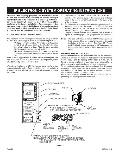
IP ELECTRONIC SYSTEM OPERATING INSTRUCTIONSAttention: For shipping purposes, the Electronic ControlModule and Receiver Plate assembly is loosely packagednear the left side of the appliance. It is necessary that the receiverplate assembly be secured to the left front flange of theappliance at the time of installation. To secure, remove thetwo lower screws in the left side flange of the appliance, thenplace the receiver plate assembly over the left front flangeand secure with the two screws previously removed.5.25 VDC ELECTRONIC CONTROL VALVEThe electronic control valve system includes the ability to switchthe pilot from a standing pilot mode to an intermittent pilot mode.• IPI Mode - In the Intermittent Pilot mode, when the unit isturned ON, it will cause spark to the pilot, light the pilot,then allow the burner to light. When the unit is turned toOFF, both the burner and pilot will be OFF.• CPI Mode - In the Continuous Pilot mode, the pilot remainsON continuously even when the burner is turnedOFF.Note: A small toggle switch is located on the receiver plate (leftside of unit) that is used to switch from IPI (upward position) to theCPI (downward position). See Figure 25.When the unit is turned to ON, the electrical current will energizea spark to the pilot igniter. Once the pilot sensor heats up (after afew seconds), the valve will be energized, allowing gas to flow tothe burner.1. Follow the SAFETY and LIGHTING INSTRUCTIONS for IntermittentPilot controls found in this manual, and on labelsfound in the control compartment located in the lower cavityof the appliance.2. During the operating season (or in power outage periods), it isrecommended that the pilot remain in the CPI (standing pilotmode) to reduce cold start issues, and/or conserve batterybackup power during a power outage.3. The gas valve has inlet and outlet pressure taps as shown inFigure 25. Refer to page 11 for gas pressure requirements.Note:The gas control has a manual HI/LO flame adjustmentknob (regulator) that allows you to increase or decreasethe height of the burner flame. See Figure 25. Rotatethe HI/LO knob counterclockwise to “HI” to increase theflame height, and clockwise to “LO” to decrease the flameheight.OPTIONAL REMOTE CONTROLSOptional remote controls are available for use with this appliance.There is an area on the Receiver Plate (between the ElectronicControl module and the back-up battery pack) that the RemoteReceiver should be placed. A velcro pad is pre-attached to theplate assembly for quick attachment of the remote receiver.To connect the remote receiver to the appliance, first disconnectthe ON/OFF switch wires from the white and green wire connectorsand connect the wires from the remote receiver to the greenand white wire connectors. See Figure 25.Follow the instructions included with the remote control for programmingand other operational information.9 PIN CONNECTORDFCELECTRONICCONTROLMODULEGROUNDSPARK RODIGNITORSENSORPILOTSENSOROPTIONALREMOTECONTROLRECEIVERLOCATIONAA (4)BATTERYBACKUPIPICPIRECEIVER PLATEPILOT SELECTOR SWITCHIPI - INTERMITANT PILOT (UP)CPI - CONTINUOUS PILOT (DOWN)GAS VALVEPILOTASSEMBLYMANUALHI/LOREGULATOROUTLETPRESSURETAPINLETPRESSURETAPMANUAL ON/OFF OPERATIONAL SWITCHNOTE: ADDITIONAL ON/OFF SWITCH & WIRING INCLUDEDTO INSTALL SWITCH TO SIDE OF SURROUND PANEL.SEE PAGE 14.Figure 25Page 2830816-1-0912