Manual - Unvented Gas Log Heater or Vented Decorative Appliance
Manual - Unvented Gas Log Heater or Vented Decorative Appliance
Manual - Unvented Gas Log Heater or Vented Decorative Appliance

Create successful ePaper yourself
Turn your PDF publications into a flip-book with our unique Google optimized e-Paper software.
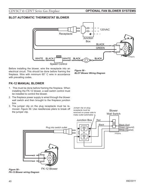
CDVSC7 & CDV7 Series <strong>Gas</strong> FireplaceOPTIONAL FAN BLOWER SYSTEMSBLOT AUTOMATIC THERMOSTAT BLOWERReceptacleJunctionBox120VACBLACKGREENWHITEBLACKWHITEBLACKBLACKFP2675Speed ControlBef<strong>or</strong>e installing the blower, wire the receptacle into anelectrical circuit. This should be done bef<strong>or</strong>e framing thefireplace. Wire with minimum 60° C wire in acc<strong>or</strong>dancewith prevailing codes.Figure 58 -BLOT Blower Wiring DiagramFK-12 MANUAL BLOWERFP26751. This must be done bef<strong>or</strong>e framing the fireplace. BLOT When blower wiringinstalling the FK-12 blower, a wall switch control mustbe installed to control the blower.2. The fireplace power supply is wired through the blowerwall switch and then brought to the fireplace junctionbox.3. The jumper clip on the plug receptacle must be removed.Figure 59. Use needlenose pliers to break off receptacle must beJumper clip on plugthe jumper clip.removed on power side tomake outlet switchableBlowerWall SwitchJunction BoxRedPlug into switch outletBlackFP2676Black (live)Green (ground)White (neutral)Figure 59 -FK-12 Blower wiring DiagramFK-12 Blower40 69D3011FP2676FK12 wiring