Manual - Unvented Gas Log Heater or Vented Decorative Appliance
Manual - Unvented Gas Log Heater or Vented Decorative Appliance
Manual - Unvented Gas Log Heater or Vented Decorative Appliance
- No tags were found...

Create successful ePaper yourself
Turn your PDF publications into a flip-book with our unique Google optimized e-Paper software.
CAUTION<br />
REMOTE WALL SWITCH & Blower INSTALLATION<br />
BLDV7 Series <strong>Gas</strong> Fireplace<br />
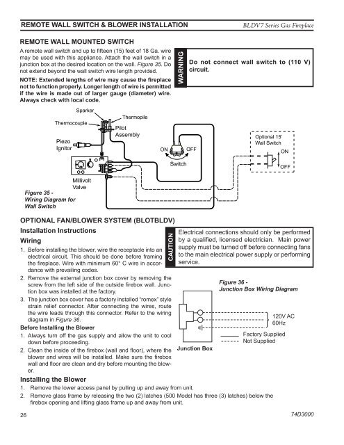
Remote Wall mounted Switch<br />
A remote wall switch and up to fifteen (15) feet of 18 Ga. wire<br />
may be used with this appliance. Attach the wall switch in a<br />
junction box at the desired location on the wall. Figure 35. Do<br />
not extend beyond the wall switch wire length provided.<br />
NOTE: Extended lengths of wire may cause the fireplace<br />
not to function properly. Longer length of wire is permitted<br />
if the wire is made out of larger gauge (diameter) wire.<br />
Always check with local code.<br />
WARNING<br />
Do not connect wall switch to (110 V)<br />
circuit.<br />
Piezo<br />
Ignit<strong>or</strong><br />
Sparker<br />
Thermocouple<br />
Thermopile<br />
Pilot<br />
Assembly<br />
ON<br />
OFF<br />
Optional 15’<br />
Wall Switch<br />
ON<br />
OFF<br />
PILOT<br />
ON<br />
HI<br />
LO<br />
Switch<br />
OFF<br />
Millivolt<br />
Valve<br />
Figure 35 -<br />
Wiring Diagram f<strong>or</strong><br />
Wall Switch<br />
OPTIONAL FAN/BLOWER SYSTEM (BLOTBLDV)<br />
Installation Instructions<br />
Wiring<br />
1. Bef<strong>or</strong>e installing the blower, wire the receptacle into an<br />
electrical circuit. This should be done bef<strong>or</strong>e framing<br />
the fireplace. Wire with minimum 60° C wire in acc<strong>or</strong>dance<br />
with prevailing codes.<br />
2. Remove the external junction box cover by removing the<br />
screw from the left side of the outside firebox wall. Junction<br />
box was installed at the fact<strong>or</strong>y. FP2919<br />
3. The junction box cover has a fact<strong>or</strong>y installed “romex” DV wiring style diagram<br />
strain relief connect<strong>or</strong>. After connecting the wires, route<br />
the wire leads through this connect<strong>or</strong>. Refer to the wiring<br />
diagram in Figure 36.<br />
Bef<strong>or</strong>e Installing the Blower<br />
1. Always turn off the gas supply and allow the unit to cool<br />
down bef<strong>or</strong>e proceeding.<br />
2. Clean the inside of the firebox (wall and flo<strong>or</strong>), where the<br />
blower and wires will be installed. Make sure the firebox<br />
wall and flo<strong>or</strong> are clean and dry bef<strong>or</strong>e mounting the blower.<br />
Installing the Blower<br />
1. Remove the lower access panel by pulling up and away from unit.<br />
Electrical connections should only be perf<strong>or</strong>med<br />
by a qualified, licensed electrician. Main power<br />
supply must be turned off bef<strong>or</strong>e connecting fans<br />
to the main electrical power supply <strong>or</strong> perf<strong>or</strong>ming<br />
service.<br />
Junction Box<br />
Figure 36 -<br />
Junction Box Wiring Diagram<br />
FP1912<br />
Junction box wiring<br />
2. Remove glass frame by releasing the two (2) latches (500 Model has three (3) latches) below the<br />
8/08<br />
firebox opening and lifting glass frame up and away from unit.<br />
120V AC<br />
60Hz<br />
Fact<strong>or</strong>y Supplied<br />
Not Supplied<br />
26<br />
74D3000