Processing and working instructions HPL and HPL elements PR ...
Processing and working instructions HPL and HPL elements PR ...
Processing and working instructions HPL and HPL elements PR ...

Create successful ePaper yourself
Turn your PDF publications into a flip-book with our unique Google optimized e-Paper software.
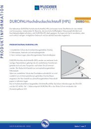
<strong>PR</strong>ODUCT INFORMATION<br />
<strong>Processing</strong> <strong>and</strong> <strong>working</strong> <strong>instructions</strong><br />
<strong>HPL</strong> <strong>and</strong> <strong>HPL</strong> <strong>elements</strong><br />
TIPS IN ADVANCE: “PLEASE NOTE!”<br />
The stress on tools when <strong>working</strong> with DUROPAL <strong>HPL</strong> is relatively high, due to the corresponding hardness<br />
of the surface, which is laminated with melamine resin. Working with DUROPAL <strong>HPL</strong> therefore requires<br />
tools with carbide-tipped blades, <strong>and</strong> for certain processes even diamond-tipped tool blades. In order to<br />
achieve the best results when <strong>working</strong> with unbonded panels, please note the following requirements:<br />
• Always work on a firm, level surface<br />
• Vibrations <strong>and</strong> flapping of the panels should be avoided at all times<br />
• Sharp blades <strong>and</strong> smooth tool function are important. Damage, splintering or bulging of the décor side<br />
is usually due to incorrect processing or unsuitable tools. Caution: Any nicks or notches created will<br />
lead to the formation of cracks in the event of later temperature or humidity fluctuations!<br />
If the décor surface is pushed over the supporting surface, take care to use a guide or support which<br />
moves along with the DUROPAL <strong>HPL</strong>. When machining with the aid of power tools, corrugated support<br />
surfaces can also be used as an alternative, which will ensure that the contact area is kept to a minimum.<br />
1. STOrAgE AND TrANSPOrT<br />
1.1 Transport<br />
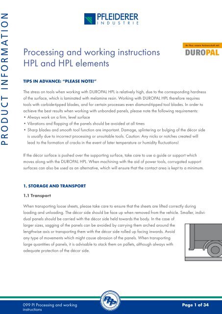
When transporting loose sheets, please take care to ensure that the sheets are lifted correctly during<br />
loading <strong>and</strong> unloading. The décor side should be face up when removed from the vehicle. Smaller, individual<br />
panels should be carried with the décor side held towards the body. In the case of<br />
larger sizes, sagging of the panels can be avoided by carrying them arched around the<br />
lengthwise axis or transporting them with the décor side rolled up facing inwards. Avoid<br />
any type of movements which might cause abrasion of the panels. When transporting<br />
large quantities of panels, it is advisable to stack them on pallets, although always with<br />
adequate protection of the décor side.<br />
099 PI <strong>Processing</strong> <strong>and</strong> <strong>working</strong> Page 1 of 34<br />
<strong>instructions</strong>
<strong>PR</strong>ODUCT INFORMATION<br />
1.2 Storage<br />
DUROPAL <strong>HPL</strong> must be protected against damp <strong>and</strong> should be kept in storage areas<br />
with normal climatic conditions. Stacks of panels should be stored horizontally - or<br />
inclined at an angle of 80°, in which case care should be taken to ensure that the panels<br />
are supported over the entire surface, <strong>and</strong> prevented from slipping by a counterweight<br />
on the ground. The panels should always be placed with the décor sides facing each<br />
other. Please follow the acclimatisation <strong>instructions</strong> before use – see “Preliminary treatment”!<br />
1.3 Storage of DUrOPAL real metal laminates<br />
The panels should ideally be stored in closed rooms under normal interior room conditions (temperature<br />
18–25 °C, relative air humidity 50–65 %). The panels must always be stored horizontally, with the edges<br />
flush, on a level surface, <strong>and</strong> be covered with plastic film. Where this is not possible, the panels should be<br />
inclined at an angle of 80°, in which case care should be taken to ensure that the panels are supported<br />
over the entire surface, <strong>and</strong> prevented from slipping by a counterweight on the ground. The top panel must<br />
be completely covered by a cover board.<br />
DUROPAL real metal laminates are supplied with a laminated film which is heat-resistant up to<br />
80 °C. This protective film should be removed after six months at the latest, otherwise damage<br />
may occur to the metal surface.<br />
1.4 Storage of DUrOPAL <strong>HPL</strong> <strong>elements</strong><br />
Store on a dry, level surface under normal climatic conditions wherever possible, e.g. in a warehouse, so<br />
that the Duropal <strong>HPL</strong> <strong>elements</strong> are not exposed to the direct effects of water or moisture. Avoid exposure to<br />
direct sunlight.<br />
099 PI <strong>Processing</strong> <strong>and</strong> <strong>working</strong> <strong>instructions</strong> Page 2 of 34
<strong>PR</strong>ODUCT INFORMATION<br />
2. CUTTINg TO SIZE<br />
2.1 DUrOPAL <strong>HPL</strong> sheets<br />
Many tools are suitable for cutting DUROPAL <strong>HPL</strong>, although all of them must have<br />
certain properties.<br />
H<strong>and</strong>saw<br />
For individual cuts, saws with fine-toothed blades <strong>and</strong> minimal teeth alteration are<br />
recommended. Always cut at a steep angle to the sheet surface.<br />
Electric nibbler<br />
Particularly suitable for curved cuts, <strong>and</strong> can also be used for stationary installation on bench-tops.<br />
H<strong>and</strong>-held circular saw<br />
Always turn the décor side down when processing. Always use a fence in order to obtain straight,<br />
neat cuts.<br />
Electric jig saw<br />
Always turn the décor side down when processing. Ensure that the undersurface is clean, <strong>and</strong> ideally<br />
protected by felt.<br />
Circular saw bench<br />
The décor side must always face upwards. The panel requires good contact pressure in the area of the saw<br />
blade, e.g. by means of a batten or ideally height-adjustable pressure rollers. Accurate saw guidance <strong>and</strong><br />
correct blade protrusion must be ensured at all times. A circular table saw can also be used to cut sheets in<br />
stacks. Carbide-tipped saw blades have a long service life, but must be h<strong>and</strong>led very carefully because of<br />
their high sensitivity to shocks <strong>and</strong> impacts.<br />
Tooth spacing: 10 – 15 mm<br />
Speed: 3,000 – 4,000 rpm<br />
Cutting speed: 50 – 100 m/s<br />
Feed speed: 10 – 30 m/min<br />
Saw blades with carbide-tipped, concave teeth cutting with both sides produce the cleanest cut edges.<br />
Saw blades below 2 mm in thickness are in most cases not rigid enough, <strong>and</strong> will result in imperfect edges.<br />
099 PI Be- <strong>Processing</strong> und Verarbeitung <strong>and</strong> <strong>working</strong> <strong>HPL</strong><strong>instructions</strong> und <strong>HPL</strong>-Elemente - 061030 Seite Page 3 3 von of 34
<strong>PR</strong>ODUCT INFORMATION<br />
The usual tooth shapes<br />
The flat tooth, the simplest variant, is easy <strong>and</strong> inexpensive to re-sharpen.<br />
The replaceable tooth is the universal tooth shape for sizing <strong>and</strong> cutting for counter rotation.<br />
The benefits come from the cut width separation <strong>and</strong> the tip advance.<br />
The Duplovit tooth offers a low tip advance <strong>and</strong> double-sided shaft angle due to its hollow<br />
grinding. The benefits also come from the double-sided engagement of the teeth, although there<br />
is no cut width separation. Maintenance is also more complex.<br />
The Duplovit tooth with double-sided chamfer is the special shape <strong>and</strong> usually the only<br />
possibility of obtaining a clean upper <strong>and</strong> lower cutting edge without use of a scoring blade.<br />
Maintenance is even more complex.<br />
The roof Duplovit is a combination of roof <strong>and</strong> Duplovit tooth. The face-angled tooth ensures<br />
preliminary cutting <strong>and</strong> holds the saw blade very stable laterally. The Duplovit tooth with its tip<br />
advance <strong>and</strong> double-sided shaft angle ensures neat edging with long tool life. Advantages:<br />
• optimum edges thanks to the four-way cut separation<br />
• universal saw blade for craft businesses<br />
The trapezoid flat tooth: Besides the individual tooth shapes, there are also tooth shapes in<br />
groups, called grouped teeth. The trapezoid flat tooth has a slightly higher flat tooth chamfered<br />
on both sides, followed by a slightly lower flat tooth without chamfer. This produces a very good<br />
cut edge due to the 5-way cut separation, although maintenance is again very complex.<br />
099 PI Be- <strong>Processing</strong> und Verarbeitung <strong>and</strong> <strong>working</strong> <strong>HPL</strong><strong>instructions</strong> und <strong>HPL</strong>-Elemente - 061030 Seite Page 4 von 4 of 34
<strong>PR</strong>ODUCT INFORMATION<br />
2.2 Cutting Duropal <strong>HPL</strong> <strong>elements</strong> on one <strong>and</strong> both sides on core material<br />
Cutting with circular saws<br />
The quality of the cut edge also depends on the height setting of the saw blade. If in the case of core<br />
materials laminated both sides the upper cut edge is not clean, a higher setting of the saw blade is<br />
recommended, <strong>and</strong> in the case of an unclean lower cut edge, a lower setting of the saw blade.<br />
The best stop position must be determined in advance in individual cases. The best results are obtained<br />
with a pre-scoring saw. The combination of other factors also affects the quality of the cut edges:<br />
• Tooth shape<br />
• Number of teeth<br />
• Cutting speed<br />
• Feed speed<br />
• Entry <strong>and</strong> exit angle<br />
2.3 Cutting of Duropal window boards<br />
Use vibration-free, carbide-tipped circular saws or fine-toothed, slightly straight-set h<strong>and</strong>saws.<br />
2.4 End caps for Duropal window boards<br />
The end caps made from ABS plastic simplify the sealing of the exposed edges, <strong>and</strong> are available in all<br />
profile variants <strong>and</strong> the matching colours of white <strong>and</strong> beige.<br />
The end caps should be matched to the size of the window board. Coat the end caps <strong>and</strong> the edges with<br />
adhesive, e.g. Sikafex-221, leave to dry for approx. 2 minutes <strong>and</strong> then press the end caps firmly into<br />
place. The adhesive hardens after about one hour, producing a visually attractive <strong>and</strong> proper sealing of<br />
the exposed edges.<br />
2.5 Cutting <strong>and</strong> feed speed<br />
See the chapter “Technical information” for a description of how the cutting <strong>and</strong> feed speed determine the<br />
quality of the cut.<br />
099 PI Be- und Verarbeitung <strong>HPL</strong> und <strong>HPL</strong>-Elemente - 061030 Seite 5 von 34<br />
099 PI <strong>Processing</strong> <strong>and</strong> <strong>working</strong> <strong>instructions</strong> Page 5 of 34
<strong>PR</strong>ODUCT INFORMATION<br />
3. CUT EDgE FINISHINg AND PrOFILINg OF DUrOPAL <strong>HPL</strong> ELEMENTS<br />
Sawing should generally take place from the panel surface (décor side).<br />
3.1 Manual edge finishingg<br />
a) File, s<strong>and</strong>paper, scraper<br />
These materials are well suited for the finishing of edges. When finishing edges, always<br />
file in the correct direction from the décor towards the core material. The edges should<br />
be finished with fine files, s<strong>and</strong>paper (100 – 150 grade) or scrapers. Routered edges<br />
should first be slightly finished using s<strong>and</strong>paper, then drawn off with the scraper <strong>and</strong><br />
finally finished with fine s<strong>and</strong>paper. Ensure that any s<strong>and</strong>ing particles are completely<br />
removed.<br />
b) Plane<br />
For manual planing, we recommend the use of metal planes with HSS blades,<br />
<strong>working</strong> at a cutting angle of approx. 15°.<br />
c) H<strong>and</strong> router<br />
Protruding DUROPAL <strong>HPL</strong> panel edges can be milled flush with the aid of this tool. In order to protect<br />
the surface when <strong>working</strong>, the surface on which the h<strong>and</strong> router is supported should be coated with a<br />
non-abrasive material. Routing waste should be carefully removed before every new step.<br />
Diameter of router: 10 – 25 mm<br />
Speed of rotation: 20,000 rpm<br />
Cutting speed: 10 – 25 m/s<br />
Carbide-tipped router cutters are particularly suitable, <strong>and</strong> for larger diameters can also be fitted with<br />
cutting inserts. Better tool utilisation can be achieved with the aid of height adjustability <strong>and</strong> parallel-axis<br />
cutting. To look after your tools, ensure a panel overhang of no more than 2-3 mm.<br />
099 PI <strong>Processing</strong> <strong>and</strong> <strong>working</strong> <strong>instructions</strong> Page 6 of 34
<strong>PR</strong>ODUCT INFORMATION<br />
3.2 Edge finishing with stationary machines<br />
Spindle moulder<br />
Routing <strong>and</strong> cutting heads with replaceable carbide-tipped blades <strong>and</strong> inserts are most suitable for these<br />
tools. The use of cylindrical tools must be determined individually according to use:<br />
• Parallel-axis cutting for panels laminated on one or both sides<br />
• Cutters inclined on one side for panels laminated on one side only<br />
• Herringbone-tooth cutters for panels laminated on both sides<br />
If only DUROPAL high-pressure laminates are being milled, a speed of 12,000 rpm should be selected<br />
for a thickness of up to approx. 5 mm <strong>and</strong> a tool diameter of 100 mm. (Also note in this connection the<br />
maximum speed of the tool!)<br />
If the panels are bonded, a lower speed of 3,000-6,000 rpm is recommended.<br />
The tool life per height setting often differs significantly according to the type <strong>and</strong> shape of the tool,<br />
<strong>and</strong> also the cut quality required <strong>and</strong> the core material used.<br />
For large production runs, it is an advantage to use tools with diamond-tipped cutters. is a beneficial<br />
solution.<br />
router used as spindle moulder<br />
Routers used as spindle moulders need single- or double-cutting carbide-tipped tools with a cutting speed<br />
of 10-15 m/s. This tool should also be used for internal recesses (see chapter “Internal recesses <strong>and</strong><br />
cut-outs”).<br />
Core panels laminated on one side can be guided for vertical milling on a template – core panels laminated<br />
on both sides <strong>and</strong> loose DUROPAL high-pressure laminate on the other h<strong>and</strong> are best milled all round<br />
with only one clamping device. A 2 mm cutting allowance is sufficient in most cases. For curved edges, the<br />
milling requirement can be minimised by pre-cutting the approximate shape in advance using a b<strong>and</strong> saw.<br />
099 PI <strong>Processing</strong> <strong>and</strong> <strong>working</strong> <strong>instructions</strong> Page 7 of 34
<strong>PR</strong>ODUCT INFORMATION<br />
Surface planer<br />
Feed speed: 5 – 15 m/min<br />
Cutting speed: 12 – 15 m/s<br />
Speed of rotation: 3,000 rpm<br />
For large production runs, carbide-tipped blades should be used, since normal jointer blades have only<br />
a short tool life.<br />
Double-end profilers<br />
This process is characterised by economic processing, particularly for large production runs. The equipment<br />
from the spindle moulder (see above) is also advisable in this case.<br />
3.3 Edge finishing of Duropal window boards<br />
Edge s<strong>and</strong>ing is recommended in order to avoid stress cracking under temperature <strong>and</strong>/or humidity stress.<br />
3.4 Profiling of the edges of <strong>elements</strong><br />
The profiling of element edges, e.g. for the post-forming or soft forming process, requires tools such as the<br />
h<strong>and</strong> router, spindle moulder or the double-end profiler.<br />
4. DrILLINg OF DUrOPAL <strong>HPL</strong> AND DUrOPAL <strong>HPL</strong> ELEMENTS<br />
4.1 general<br />
Please note: Drill holes in DUROPAL <strong>HPL</strong> should always be 0.5 mm larger than the screw<br />
diameter. The screws need this slight clearance all round to prevent cracks forming in the<br />
area around the drill hole in the event of temperature <strong>and</strong> humidity fluctuations. Raised<br />
countersunk head screws require rosette washers. For our DUROPAL window boards,<br />
use only plastic washers.<br />
099 PI <strong>Processing</strong> <strong>and</strong> <strong>working</strong> <strong>instructions</strong> Page 8 of 34
<strong>PR</strong>ODUCT INFORMATION<br />
4.2 Drilling tools<br />
Twist bits<br />
Twist bits specially designed for plastics have a large pitch (steep twist) with wide cutting grooves).<br />
Tip angles of 60°- 80° are ideal for drilling DUROPAL <strong>HPL</strong>.<br />
Combi-bits<br />
Combi-bits or carbide disc drills are suitable for larger diameter drill holes.<br />
Step bits<br />
Step bits are ideal for drill holes of any type; this technique avoids double drilling.<br />
Hole cutters<br />
Hole cutters with guide pins should be used for larger drill hole diameters. If using adjustable hole cutters<br />
with guide pins, the hole must be drilled from both sides.<br />
4.3 Drilling technique<br />
When adjusting the drilling rate, ensure that the melamine surface of the DUROPAL <strong>HPL</strong> is not damaged.<br />
The cutting speed for HSS drills is approx. 0.8 m/s, <strong>and</strong> for carbide-tipped drills up to 1.6 m/s. The advisable<br />
feed rate is 0.02-0.05 mm/rev, corresponding to 1,000 revolutions for 20-50 mm drilling depth/min.<br />
The possible accumulation of material at the exit of the drill bit can be avoided by using a hardwood or<br />
laminate underlay. For large production runs, even better results can be achieved using drilling jigs, which<br />
are equipped with drilling bushes on both sides to enable firm clamping. For countersinking, the guideline<br />
speeds should be halved.<br />
099 PI <strong>Processing</strong> <strong>and</strong> <strong>working</strong> <strong>instructions</strong> Page 9 of 34
<strong>PR</strong>ODUCT INFORMATION<br />
5. INTErNAL rECESSES AND CUT-OUTS OF DUrOPAL <strong>HPL</strong> ELEMENTS<br />
5.1 general<br />
The corners of cut-outs should never have sharp angles, since these would quickly<br />
become damaged. Sharp edges can only be achieved by the joining of different cut<br />
pieces.<br />
Internal corners must always be rounded, with a minimum radius of 5 mm. In the case of<br />
internal recesses <strong>and</strong> cut-outs of over 250 mm side length, the radius must gradually be<br />
increased in accordance with the length of the side.<br />
Rounded internal recesses can be produced directly with a router, although for exact results, the corresponding<br />
radius should be pre-drilled. Ensure that the edges are free of notches. When planning to install<br />
heat sources, e.g. halogen lamps, the cut-out should be designed to include sufficient extra clearance,<br />
or should be insulated.<br />
The DUROPAL <strong>HPL</strong> surface should not be subjected to prolonged exposure to temperatures in excess<br />
of 70 °C. The different expansion coefficients should also be noted if using a combination of different<br />
materials.<br />
5.2 <strong>Processing</strong> of Duropal <strong>HPL</strong> worktops<br />
Due to the high-quality lamination of the top <strong>and</strong> reverse side, DUROPAL <strong>HPL</strong> worktops are reliably<br />
protected against the penetration of water <strong>and</strong> steam. During processing however, unprotected edges<br />
<strong>and</strong> joints can be created. Such exposed areas should therefore always be sealed during the course<br />
of the final assembly of the DUROPAL <strong>HPL</strong> <strong>elements</strong>. Otherwise the general <strong>instructions</strong> of 5.1 apply.<br />
5.3 Tools<br />
Please see chapters 2, 3 <strong>and</strong> 4. The tools <strong>and</strong> usage possibilities described also apply for the production<br />
of internal recesses <strong>and</strong> cut-outs.<br />
099 PI <strong>Processing</strong> <strong>and</strong> <strong>working</strong> <strong>instructions</strong> Page 10 of 34
<strong>PR</strong>ODUCT INFORMATION<br />
6. TECHNICAL INFOrMATION<br />
6.1 Tool information<br />
Material Work step Tool<br />
<strong>HPL</strong> Panel cutting<br />
<strong>HPL</strong> on raw<br />
chipboard panel<br />
<strong>HPL</strong> on raw<br />
chipboard panel<br />
<strong>HPL</strong> on raw<br />
chipboard panel<br />
<strong>HPL</strong> on raw<br />
chipboard panel<br />
<strong>HPL</strong> on raw<br />
chipboard panel<br />
<strong>HPL</strong> on raw<br />
chipboard panel<br />
<strong>HPL</strong> on raw<br />
chipboard panel<br />
<strong>HPL</strong> on raw<br />
chipboard panel<br />
<strong>HPL</strong> on raw<br />
chipboard panel<br />
Cutting to size<br />
Cutting to size<br />
Routing edges<br />
Routing edges<br />
Grooving<br />
Circular<br />
saw bench<br />
Circular<br />
saw bench<br />
Double-end<br />
profiler (scoring<br />
<strong>and</strong> cutting)<br />
Spindle moulder<br />
or automatic<br />
edge-finisher<br />
Double-end profiler<br />
(re-milling)<br />
Circular<br />
saw bench<br />
Cutting speed<br />
in m/s<br />
40 – 60<br />
40 – 60<br />
40 – 60<br />
40 – 60<br />
40 – 60<br />
40 – 60<br />
Grooving Spindle moulder 40 – 60<br />
Grooving<br />
Double-end<br />
profiler<br />
Grooving Router<br />
Grooving<br />
Drill<br />
Automatic dowelling<br />
machine<br />
40 – 60<br />
Speed in rpm Feed in m/min<br />
approx.<br />
3,000 – 4,000<br />
approx.<br />
3,000 – 4,000<br />
approx.<br />
6,000<br />
approx.<br />
6,000 – 9,000<br />
approx.<br />
6,000<br />
approx.<br />
3,000 – 4,000<br />
approx.<br />
6,000<br />
approx.<br />
6,000 – 9,000<br />
approx.<br />
12,000 – 18,000<br />
approx.<br />
3,000 – 6,000<br />
10 – 30<br />
By h<strong>and</strong><br />
approx. 10<br />
Mechanically<br />
approx. 6 - 20<br />
approx.<br />
6 - 20<br />
approx.<br />
3 - 8<br />
approx.<br />
3 - 8<br />
approx.<br />
6 - 20<br />
approx.<br />
3 - 8<br />
099 PI <strong>Processing</strong> <strong>and</strong> <strong>working</strong> <strong>instructions</strong> Page 11 of 34
<strong>PR</strong>ODUCT INFORMATION<br />
6.2 Feed speed<br />
Time for<br />
travel<br />
in s<br />
Feed speed in m/min. for processing lengths in m<br />
1 2 3 4 5 6 7 8 9<br />
1 60 120 180 240 300 360 420 480 540<br />
2 30 60 90 120 150 180 210 240 270<br />
3 20 40 60 80 100 120 140 160 180<br />
4 15 30 45 60 75 90 105 120 135<br />
5 12 24 36 48 60 72 84 96 108<br />
6 10 20 30 40 50 60 70 80 90<br />
7 9 17 26 34 43 52 60 69 77<br />
8 7,5 15 22,5 30 37,5 45 52,5 60 67,5<br />
9 6,7 13 20 27 34 40 47 54 60<br />
10 6 12 18 24 30 36 42 48 54<br />
Example: <strong>Processing</strong> length 5 m, feed speed 50 m/min. – time for travel: 6 s<br />
099 PI <strong>Processing</strong> <strong>and</strong> <strong>working</strong> <strong>instructions</strong> Page 12 of 34
<strong>PR</strong>ODUCT INFORMATION<br />
6.3 Cutting speed<br />
Cutting speed v in m/s in relation to tool diameter <strong>and</strong> speed<br />
Tool diameter<br />
in mm<br />
Cutting speed v in m/s<br />
400 20 40 60 80 100 120 140<br />
380 19 38 57 76 95 114 133<br />
360 18 36 54 72 90 108 126<br />
340 17 34 51 68 85 102 119<br />
320 16 32 48 64 80 96 112<br />
300 1) 15 30 45 60 75 90 105<br />
280 14 28 42 56 70 84 98<br />
260 13 26 39 52 65 78 91 104<br />
240 12 24 36 48 60 72 84 96 108<br />
220 11 22 33 44 55 66 77 88 99 110<br />
200 10 20 30 40 50 60 70 80 90 100 120<br />
180 2) 9 18 27 36 45 54 63 72 81 90 108 135<br />
160 8 16 24 32 40 48 56 64 72 80 96 120 144<br />
140 7 14 21 28 35 42 49 56 63 70 84 105 126<br />
120 6 12 18 24 30 36 42 48 54 60 72 90 108 126<br />
100 5 10 15 20 25 30 35 40 45 50 60 75 90 105<br />
80 4 8 12 16 20 24 28 32 36 40 48 60 72 84<br />
60 3 6 9 12 15 18 21 24 27 30 36 45 54 63<br />
40 2 4 6 8 10 12 14 16 18 20 24 30 36 42<br />
20 1 2 3 4 5 6 7 8 9 10 12 15 18 21<br />
10 0,5 1 1,5 2 2,5 3 3,5 4 4,5 5 6 7,5 9 10,5<br />
Speed n of the tool<br />
shaft in rpm x 1,000<br />
1 2 3 4 5 6 7 8 9 10 12 15 19 20<br />
Examples:<br />
1) Carbide-tipped circular saw blade<br />
2) Synchronously adjustable router head with clamped herringbone-shaped reversible carbide tips<br />
099 PI <strong>Processing</strong> <strong>and</strong> <strong>working</strong> <strong>instructions</strong> Page 13 of 34
<strong>PR</strong>ODUCT INFORMATION<br />
7. WOrKINg WITH DUrOPAL <strong>HPL</strong> AND DUrOPAL <strong>HPL</strong> ELEMENTS<br />
7.1 general<br />
DUROPAL <strong>HPL</strong> with a thickness of less than 2 mm needs a flat, stress-free core material with minimum flex.<br />
A smooth surface is an essential requirement for a permanently good result. The right adhesives, application<br />
quantity, pressure <strong>and</strong> press temperature are equally important.<br />
Since DUROPAL <strong>HPL</strong> may be subject to slight dimensional changes, depending on the air humidity <strong>and</strong><br />
temperature, these properties must always be taken into account when <strong>working</strong> with DUROPAL <strong>HPL</strong>.<br />
7.2 Core material<br />
The following table describes the suitability of different materials as cores <strong>and</strong> their application possibilities.<br />
With all such information, it should be noted that the properties of a core materials of different composition<br />
(e.g. honeycomb with frame) can have an effect on the surface texture of the DUROPAL <strong>HPL</strong>. This should<br />
be checked in advance <strong>and</strong> taken into account.<br />
Material/properties <strong>and</strong> suitability as core material<br />
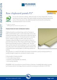
Chipboard panels<br />
On free supporting constructions, the necessary thickness must be taken into account.<br />
The fixing of the flat bonded element depends on the thickness <strong>and</strong> size of the panel.<br />
The surface quality of the DUROPAL <strong>HPL</strong> element depends largely on the structure of the<br />
chipboard panel construction, i.e. the shape of the chips, resin content, density, <strong>and</strong> in<br />
particular on the s<strong>and</strong>ing quality of the surface. Multi-ply chipboard panels are suitable<br />
as core materials. The panels should be evenly s<strong>and</strong>ed on both sides in order to prevent<br />
bowing <strong>and</strong> visual surface defects.<br />
In order to enable a short bonding <strong>and</strong> pressing time, ensure good surface absorption<br />
properties if you are using water-based bonding system. The surface must also have a<br />
resistance to delamination strength of at least 1.2 N/mm2 to avoid detachment of the<br />
laminate (DIN 52 366). Please contact us in the event of any further questions on these<br />
special chipboard panels.<br />
099 PI <strong>Processing</strong> <strong>and</strong> <strong>working</strong> <strong>instructions</strong> Page 14 of 34
<strong>PR</strong>ODUCT INFORMATION<br />
MDF panels Particularly suitable for profiling, although not self-supporting in low thicknesses.<br />
Hard fibre panels<br />
Plywood panels<br />
Veneered panels<br />
Not self-supporting. Surface textures containing paraffin must be s<strong>and</strong>ed before bonding, but are<br />
usually supplied already treated. Density 850 kg/m3, other properties according to EN 622.<br />
Self-supporting. In order to ensure a smooth surface preferably use laminboard with narrow strips<br />
<strong>and</strong> a softwood covering layer.<br />
Thin panels are not self-supporting, the fixing method depends on the thickness <strong>and</strong> size.<br />
Softwoods such as poplar <strong>and</strong> abachi are suitable for bonding.<br />
Solid timber Should only be used for small areas. Risk of deformation!<br />
Honeycomb<br />
structure<br />
Foam materials<br />
7.3 Preliminary treatment<br />
Suitable as a component of composite core materials or in combination with a framework<br />
construction.<br />
Self-supporting for vertical surfaces, also suitable as a component of composite panels. Excellent<br />
heat insulation. Hard foams on a synthetic resin basis, such as polystyrene, PVC, phenol, polyurethane,<br />
are suitable for bonding. Please consult the manufacturer in all cases before bonding.<br />
The DUROPAL <strong>HPL</strong> <strong>and</strong> the core materials must always be conditioned together, in order to equalise the<br />
moisture content of the components. Materials with too high a moisture content tend to contract after a<br />
period of drying. This can result in cracks <strong>and</strong> distortion. Materials which are too dry are difficult to work<br />
<strong>and</strong> can later exp<strong>and</strong>, once again leading to distortion. The correct conditioning is achieved at a room<br />
temperature of approx. 18–25 °C <strong>and</strong> 50–65 % relative humidity.<br />
The following points must also be observed:<br />
• adequate air circulation around the DUROPAL <strong>HPL</strong> for at least 10 days.<br />
• alternatively the core panels <strong>and</strong> laminates can be stored for at least three days, stacked in the same<br />
order as they will later be bonded together. In this case, the air humidity should be similar to that in<br />
which the panels will later be used.<br />
099 PI <strong>Processing</strong> <strong>and</strong> <strong>working</strong> <strong>instructions</strong> Page 15 of 34
<strong>PR</strong>ODUCT INFORMATION<br />
• DUROPAL <strong>HPL</strong> which is intended for a DUROPAL <strong>HPL</strong> element should be stacked for at least three days<br />
with the reverse sides facing each other. Joint conditioning together with the core material can then be<br />
dispensed with, provided that this has been stored properly. If the DUROPAL <strong>HPL</strong> will later be exposed<br />
to consistently low relative air humidity, the conditioning should be carried out accordingly, e.g.<br />
20 hours at 40 °C or 10 hours at 50 °C. The adhesives should be stored at room temperature. Bonding<br />
must be carried out immediately after conditioning.<br />
Please note: This information applies only for processing in normal climatic conditions. For extreme<br />
conditions, please consult us.<br />
7.4 Stress equalisation<br />
When two different materials are bonded together, tension always occurs. Core materials must therefore<br />
be laminated on both sides with materials which are subject to the same dimensional changes under the<br />
effects of heat <strong>and</strong> moisture. This applies particularly if the finished composite panel is to be self-supporting,<br />
<strong>and</strong> will not be held by any rigid construction. As the size of the surface increases, more care needs<br />
to be taken in selecting a surface to balance it, as well as the density, symmetry of structure <strong>and</strong> rigidity of<br />
the core.<br />
The best results will be achieved by selecting the same DUROPAL <strong>HPL</strong> type in identical thickness for the lamination<br />
on both sides. When using <strong>HPL</strong> with film (for protection of the surface), care must again be taken<br />
to ensure a symmetrical arrangement. The DUROPAL <strong>HPL</strong> cut-outs must always have the same direction of<br />
grain. DUROPAL <strong>HPL</strong> must be bonded to the core material using the same s<strong>and</strong>ing direction on both sides.<br />
It is best to use our <strong>HPL</strong> balancing material of equal thickness or also best suited for this purpose.<br />
7.5 Working with DUrOPAL real metal laminates<br />
The <strong>working</strong> of different types of materials into composite <strong>elements</strong> always leads to stresses between the<br />
different materials. Core materials must therefore be laminated on both sides with materials which are subject<br />
to the same dimensional changes under the effects of heat <strong>and</strong> moisture. Particular care must be taken<br />
to maintain symmetry of structure if the composite element is to be self-supporting. When <strong>working</strong> with<br />
DUROPAL real metal laminates, the correct direction of the décor pattern must also be followed. To make<br />
this easier, the protective film is marked with direction arrows to show the direction of the décor.<br />
099 PI <strong>Processing</strong> <strong>and</strong> <strong>working</strong> <strong>instructions</strong> Page 16 of 34
<strong>PR</strong>ODUCT INFORMATION<br />
7.6 Bonding<br />
Please note: For the gluing <strong>and</strong> bonding of DUROPAL <strong>HPL</strong>, adhesives should be used which have<br />
good adhesive strength <strong>and</strong> adequate resistance to extremes of temperature <strong>and</strong> moisture.<br />
7.6.1 Adhesives, overview<br />
• Dispersion adhesives (e.g. PVAc adhesives = white adhesives)<br />
• Condensation resin adhesives (e.g. urea, resorcinol <strong>and</strong> phenolic resin adhesives)<br />
• Contact adhesives (e.g. polychloroprene [PCP] adhesives)<br />
• Mixed adhesives (e.g. epoxy, unsaturated polyester <strong>and</strong> polyurethane adhesives)<br />
• Hot-melt adhesives (for special applications only)<br />
For the suitability of adhesives, please consult the following table:<br />
Wood-based<br />
core materials<br />
(panels or<br />
honeycomb)<br />
Paper<br />
honeycomb<br />
Foams <strong>and</strong><br />
honeycomb<br />
made of:<br />
Dispersion adhesives<br />
e.g. PVAc<br />
adhesives<br />
Condensation<br />
resin adhesives<br />
e.g. urea, resorcin<br />
<strong>and</strong> phenol<br />
resin adhesives<br />
Contact adhesives<br />
e.g. polychloroprene,<br />
nitrate rubber<br />
adhesives<br />
Mixed adhesives<br />
e.g. epoxy,<br />
polyurethane<br />
adhesives<br />
Hot-melt<br />
adhesives<br />
n n n n n<br />
n n n n n<br />
n 2) n 2)<br />
• Polystyrene n 1) n 1)<br />
• PVC<br />
• Phenol n n n n n<br />
• Polyurethane n 2) n n n n<br />
1) Without ingredients which attack polystyrene<br />
2) PVC or polyurethane <strong>and</strong> adhesives must be suitable for each other<br />
099 PI <strong>Processing</strong> <strong>and</strong> <strong>working</strong> <strong>instructions</strong> Page 17 of 34
<strong>PR</strong>ODUCT INFORMATION<br />
7.6.2 guideline values for the stress resistance of adhesives (empirical)<br />
Adhesive type<br />
Dispersion adhesives:<br />
Temperature resistance<br />
(approximate values) 1)<br />
PVAc adhesives -20 to +70 °C D 1/D 2<br />
2-component PVAc adhesives -20 to +100 °C D 3<br />
Condensation resin adhesives:<br />
Urea resin with high<br />
elongation agent component<br />
-20 to +120 °C D 2<br />
Melamine/urea resin -20 to +120 °C D 3/D 4<br />
Phenol, resorcin resin -20 to +140 °C D 3/D 4<br />
Contact adhesives:<br />
Contact adhesives<br />
without hardener<br />
Contact adhesives<br />
with hardeners<br />
Contact adhesives<br />
with resin hardeners<br />
Reaction adhesives:<br />
Epoxy, unsaturated polyester<br />
<strong>and</strong> polyurethane adhesives<br />
-10 to +50 °C D 1<br />
-10 to +100 °C D 2<br />
Stress resistance in accordance<br />
with DIN EN 204 2)<br />
Consul manufacturer Consul manufacturer<br />
-20 to +100 °C D 3/D 4<br />
Hot-melt adhesives -10 to +60 °C D 1<br />
Special hot-melt adhesives -10 to +90 °C D 1<br />
The specified guideline values refer only to the bonded joint.<br />
1) The specified plus values refer to short-term stress (up to 30 min.) up to these maximum temperatures.<br />
2) The core material <strong>and</strong> edge protection must comply with the relevant stresses..<br />
The figures on temperature resistance apply only for short-term stress to the bonded joint.<br />
The long-term resistance of the composite element depends on several factors, such as the type <strong>and</strong> class<br />
of the DUROPAL <strong>HPL</strong>, air humidity, temperature effects <strong>and</strong> the core material. Since the adhesives within<br />
the groups listed how different properties <strong>and</strong> are under continual further development, the manufacturer<br />
should always be consulted for special applications.<br />
099 PI <strong>Processing</strong> <strong>and</strong> <strong>working</strong> <strong>instructions</strong> Page 18 of 34
<strong>PR</strong>ODUCT INFORMATION<br />
7.6.3 Bonding procedure<br />
Preparation work: Clean both sides of the core material <strong>and</strong> the DUROPAL <strong>HPL</strong> thoroughly.<br />
Dust, grease, oil or perspiration can leave marks on the surface after bonding.<br />
These can be easily removed with organic solvents (e.g. acetone, white spirit or petrol).<br />
Further <strong>instructions</strong> on cleaning <strong>and</strong> care of DUROPAL <strong>HPL</strong> are given in the chapter of<br />
the same name “DUROPAL <strong>HPL</strong>”.<br />
Bonding should be carried out at a temperature of approx. 18-25 °C <strong>and</strong> a relative air humidity of 50-65<br />
%. We recommend carrying out a test under the same conditions which will prevail during bonding. For all<br />
types of solvents <strong>and</strong> hardeners, please follow the safety <strong>instructions</strong> of the professional trade associations.<br />
7.6.4 Edging of DUrOPAL window boards<br />
The DUROPAL window board is a wood-based material. Wood-based materials can show signs of<br />
swelling under the effect of moisture. It is therefore advisable to seal all exposed cut edges properly<br />
before installation: this applies particularly for the Eco type.<br />
Sealing can be carried out using high-quality DUROPAL <strong>HPL</strong> edging strips or end caps, <strong>and</strong> also with<br />
simpler edging materials. According to available experience, Sealing with waterproof <strong>and</strong> temperature-<br />
resistant adhesives or a sealant such as Sikaflex-221 is also sufficient in some cases to prevent the<br />
penetration of moisture (please follow the corresponding usage <strong>instructions</strong> for the adhesive or sealant).<br />
For the sealing of exposed cut edges, every carton pack contains the corresponding DUROPAL <strong>HPL</strong><br />
edging strip. In instances where work has to be carried out more quickly, we offer the types Reno <strong>and</strong><br />
Hydro window boards with significantly improved swelling properties, which can also be installed without<br />
corresponding edge sealing. However, if the front profile edge is to be plastered in, or if the possibility<br />
exists that it might come into direct contact with water, the edge in the profile area must also be properly<br />
sealed for the types Reno <strong>and</strong> Hydro. This also applies if the original width has to be cut down. In this case,<br />
the rear long edge must be sealed for all types.<br />
099 PI <strong>Processing</strong> <strong>and</strong> <strong>working</strong> <strong>instructions</strong> Page 19 of 34
<strong>PR</strong>ODUCT INFORMATION<br />
In order to achieve good results, please stick to the guideline values of the following table.<br />
It should also be taken into account that these values depend on the <strong>working</strong> <strong>and</strong> climate conditions,<br />
as well as the type of core material <strong>and</strong> the adhesive quality.<br />
guideline values for bonding<br />
Adhesive type<br />
Dispersion adhesives:<br />
PVAc adhesives<br />
2-component<br />
PVAc adhesives<br />
Condensation<br />
resin adhesives:<br />
Urea resin,<br />
melamine/urea resin<br />
Phenolharz,<br />
Resorcinharz<br />
Contact adhesives:<br />
with <strong>and</strong> without<br />
hardener<br />
Adhesive<br />
application<br />
in g/m 2<br />
90 – 150 on <strong>HPL</strong><br />
or core material<br />
90 – 150 on <strong>HPL</strong><br />
or core material<br />
90 – 150 on <strong>HPL</strong><br />
or core material<br />
100 – 180 on <strong>HPL</strong><br />
or core material<br />
150 – 200 on <strong>HPL</strong><br />
<strong>and</strong> core material<br />
Waiting time<br />
(open) 1) in min.<br />
1 - 30<br />
1 – 30 depending<br />
on component<br />
composition<br />
Pressing<br />
pressure<br />
2) 3)<br />
in bar<br />
approx.<br />
3<br />
approx.<br />
3<br />
2 - 20 3 - 5<br />
approx. 2 – 15 3 - 5<br />
Depending on<br />
ambient temperature<br />
<strong>and</strong> adhesive type<br />
(finger test)<br />
Pressing temperature /<br />
pressing time 4) Proce -<br />
dure<br />
20 °C 40 °C 60 °C<br />
8 - 60<br />
min.<br />
4 - 12<br />
min.<br />
45 - 160<br />
sec.<br />
According to manufacturer’s<br />
specifications<br />
15 –<br />
180 min.<br />
5 – 30<br />
min.<br />
1 – 12<br />
min.<br />
Depending on hardener system<br />
approx.<br />
8 hrs.<br />
Pressing time<br />
depending on<br />
hardener system<br />
At least 5 At least 1 min. pressed c)<br />
with added hardener These are special adhesive settings for which no general guideline values can be specified.<br />
Reaction adhesives:<br />
Epoxy, unsaturated<br />
polyester <strong>and</strong> polyurethane<br />
adhesives<br />
Hot-melt adhesives<br />
100 – 250 on <strong>HPL</strong><br />
or core material<br />
180 – 300<br />
180 – 300 on <strong>HPL</strong><br />
or core material<br />
Depending on type<br />
Extremely short<br />
Stack<br />
pressure,<br />
store flat<br />
Pressure<br />
roller<br />
Depending on type <strong>and</strong> hardener<br />
system<br />
195 – 220 °C<br />
(adhesive application temperature)<br />
1) According to DIN 16920, the waiting time (open) = the time between application of the adhesive <strong>and</strong> placing the surfaces<br />
together for bonding. To this is added the waiting time (closed) = the time between placing the adhesive surfaces together<br />
<strong>and</strong> achievement of the full pressing pressure or other measures causing bonding (hardening) (e.g. the hardening tempera-<br />
ture). When bonding in the heating press, the full pressure must be applied immediately after loading the press, in order to<br />
prevent distortion of the composite <strong>elements</strong> or premature drying of the adhesive coating.<br />
2) 1 bar ≈ 1 kp/cm 2 = 0,1 N/mm 2 ≈ 100 k Pa<br />
3) calculate the pressing pressure for hydraulic presses, see the Appendix (Item 8)<br />
4) The pressing time is not always identical to the time until reaching final strength. Depending on the procedure, an adequate<br />
time interval must be left after pressing before further processing.<br />
099 PI <strong>Processing</strong> <strong>and</strong> <strong>working</strong> <strong>instructions</strong> Page 20 of 34<br />
a)<br />
a)<br />
b)<br />
b)<br />
d)<br />
e)
<strong>PR</strong>ODUCT INFORMATION<br />
Pressing temperature<br />
To produce tension-free DUROPAL <strong>HPL</strong> <strong>elements</strong>, a pressing temperature of approx. 20 °C is recommended.<br />
At higher temperatures, the setting times can be reduced. A temperature of 60 °C should not be<br />
exceeded during pressing, since this may result in bowing <strong>and</strong> a change in the surface texture. For special<br />
bonding at higher pressing temperatures, please note the following guideline values, in order to avoid<br />
damage to the material. In case of bonding systems which require a higher temperature, please consult us.<br />
Temperature Time<br />
70 °C 10 min<br />
80 °C 5 min<br />
90 °C 3 min<br />
100 °C 2 min<br />
Applying the adhesive <strong>and</strong> the pressing procedure<br />
Spread the adhesive evenly <strong>and</strong> sparingly over the complete surface. For DUROPAL <strong>HPL</strong> <strong>elements</strong>, both<br />
sides must be coated with the same amount of adhesive in order to avoid bowing. This applies particularly<br />
to water-based bonding systems.<br />
general calculation of the pressing pressure for hydraulic presses<br />
For the setting of the correct pressing pressure with different panel dimensions, it is important is to calculate<br />
the piston pressure <strong>and</strong> the corresponding manometer pressure.<br />
Please use the following formula for the calculations:<br />
Necessary pressure in bar Panel area in cm² = manometer pressure<br />
x<br />
Number of pistons Piston area in cm² in bar<br />
Piston area = r²π<br />
099 PI <strong>Processing</strong> <strong>and</strong> <strong>working</strong> <strong>instructions</strong> Page 21 of 34
<strong>PR</strong>ODUCT INFORMATION<br />
The application of the individual adhesives is explained below:<br />
a) Dispersion adhesives<br />
These include PVAc adhesives <strong>and</strong> 2-component PVAc dispersion adhesives. Apply the adhesive with a<br />
toothed spreader or h<strong>and</strong> roller. This can also be done with adhesive application machines or four-roller<br />
machines. Cold pressing is carried out using screw clamps, spindle presses or single-/multi-daylight presses,<br />
<strong>and</strong> warm pressing with single- or multi-daylight presses, short cycle presses, roller presses or double-belt<br />
presses. Take care to observe the pressing times/temperatures accurately with sparing <strong>and</strong> even adhesive<br />
application.<br />
b) Condensation resin adhesives<br />
These include urea resin, melamine-urea resin, phenolic resin <strong>and</strong> resorcinol resin. Phenolic- <strong>and</strong> resorcinol<br />
resin are used principally for DUROPAL <strong>HPL</strong> <strong>elements</strong> which require high resistance to exposure to flames.<br />
Condensation resin adhesives require corresponding additives in order to make the adhesive joint elastic.<br />
The guideline values can vary according to the hardener type. Impurities consisting of remains of adhesive<br />
or hardener cannot be removed from the DUROPAL <strong>HPL</strong> surface after bonding without damaging the material.<br />
Ensure therefore that these are completely removed before bonding. For cold <strong>and</strong> warm pressing, the<br />
same tool specifications apply as for dispersion adhesives.<br />
c) Contact adhesives<br />
Without hardener: When applying with a toothed spreader, the application direction on the core material<br />
<strong>and</strong> laminate should be at right-angles to one another. The adhesive can also be applied with a brush,<br />
or by spraying <strong>and</strong> pouring systems. In all cases, great care <strong>and</strong> good ventilation must be ensured when<br />
<strong>working</strong>. Contact adhesives require a short, powerful contact pressure. The open time can be reduced by<br />
accelerated drying of the adhesive films, although over-drying should be avoided. Dried-on adhesive films<br />
can be reactivated by heat, e.g. infrared radiation.<br />
The pressing procedure is carried out as described.<br />
With hardener: This adhesive enables higher stress <strong>and</strong> temperature resistance of the joint. For further<br />
information, please consult the manufacturer.<br />
d) Mixed adhesives<br />
General <strong>working</strong> recommendations cannot be given here, since this category is divided into different types<br />
<strong>and</strong> used only for special bonding.<br />
e) Hot-melt adhesives<br />
These are used principally for edge bonding.<br />
099 PI <strong>Processing</strong> <strong>and</strong> <strong>working</strong> <strong>instructions</strong> Page 22 of 34
<strong>PR</strong>ODUCT INFORMATION<br />
7.6.5 Post-forming<br />
The core material<br />
It is important to use a material which has an even distribution of the chip sizes or thickness over the whole<br />
cross-section, e.g. chipboard panels or MDF. Coarse chips in the central layer of the panel can lead to<br />
formation of cracks in the <strong>HPL</strong>, depending on the quality of the milling.<br />
Profile milling<br />
Ensure that the profile has even transitions between rounded <strong>and</strong> flat areas, <strong>and</strong> is properly s<strong>and</strong>ed.<br />
The radius of a post-formed product is defined as the radius of the profiled core material.<br />
Conditioning<br />
Follow the recommendations on storage <strong>and</strong> preliminary treatment. The postforming results can be adversely<br />
affected by deviations from these recommendations, particularly in an over-dry environment.<br />
Bonding procedures for post-forming <strong>and</strong> coating<br />
In order to avoid the formation of cracks, any surplus adhesive must be completely removed. This applies<br />
particularly at transitions between rounded <strong>and</strong> flat areas. The same special adhesive should be used for<br />
DUROPAL <strong>HPL</strong> <strong>and</strong> the balancing material, e.g. PVAc adhesive or contact adhesive.<br />
Procedures depending on system configuration (example)<br />
Das Durchlaufverfahren ist in folgende Schritte gegliedert<br />
• Sawing <strong>and</strong> profile milling of the core material<br />
• Pressing of the DUROPAL <strong>HPL</strong> (st<strong>and</strong>ard type P = post-formable) <strong>and</strong> balancing material<br />
• Router the edge of the balancing material<br />
• Application of the adhesive to the underside <strong>and</strong> edge of the DUROPAL <strong>HPL</strong> (approx. 120–180 g/m 2 )<br />
• Post-forming at 160-210 °C. A test is advisable. For continuous post-forming, the feed speed should be<br />
11-17 m/min<br />
• Removal of any projecting DUROPAL <strong>HPL</strong> by using a coarse cutter, followed by fine cutter at an angle<br />
of approx. 30°.<br />
Heat transmission<br />
In principle, two different methods can be used:<br />
• Infra red heat: stationary or continuous.<br />
• Direct heat: stationary.<br />
099 PI <strong>Processing</strong> <strong>and</strong> <strong>working</strong> <strong>instructions</strong> Page 23 of 34
<strong>PR</strong>ODUCT INFORMATION<br />
Both systems require sufficient heat to enable the subsequent post-forming. Thin DUROPAL high-pressure<br />
laminates require only a short heating period, <strong>and</strong> must be processed correspondingly faster. With continuous<br />
post-forming, the bending should begin at the end of the heating input. Any machine systems should<br />
be run up to their ideal dosing before the actual post-forming procedure, since every material responds<br />
better to a different speed <strong>and</strong> temperature. It is important that the DUROPAL <strong>HPL</strong> is exposed to uniform<br />
heat throughout the whole cross-section before the bending process is started. The corresponding required<br />
temperature depends on the laminate thickness, the surface texture <strong>and</strong> the bend profile.<br />
For continual processing machines, the maximum heating output must be set at the corresponding variable<br />
speed. Continuous post-forming should be carried out if possible using a fixed bending block.<br />
For stationary machines, a test run should be carried out in order to determine the optimum heat effect in<br />
relation to the bending speed. This should ideally be started at a high temperature, <strong>and</strong> the speed adjusted<br />
accordingly. With heating rails, the initial duration should be kept short, <strong>and</strong> maintained continuously<br />
during post-forming.<br />
Avoid too low a temperature in order to prevent the formation of cracks. Discoloration can occur if the<br />
temperature effects are too high, sometimes also accompanied by cracking, deformation or blistering.<br />
Post-forming properties of DUrOPAL real metal laminates<br />
All DUROPAL real metal laminates are produced in post-forming quality. At a thickness of 0.8 mm, a radius<br />
of 8 mm or larger can be produced for brushed surfaces, <strong>and</strong> a radius from 10 mm upwards for smooth<br />
surfaces.<br />
099 PI <strong>Processing</strong> <strong>and</strong> <strong>working</strong> <strong>instructions</strong> Page 24 of 34
<strong>PR</strong>ODUCT INFORMATION<br />
8. WOrKINg rECOMMENDATIONS FOr DUrOPAL <strong>HPL</strong>-SOLID<br />
DUROPAL <strong>HPL</strong>-Solid has a high weight factor. Its material value is considerable!<br />
Please therefore note the following recommendations for treatment <strong>and</strong> processing<br />
recommendations for the treatment <strong>and</strong> processing of DUrOPAL <strong>HPL</strong>-Solid<br />
8.1 Transport <strong>and</strong> storage<br />
8.1.1 Transport<br />
• When transporting stacks of panels, always use adequately large, level <strong>and</strong> stable pallets.<br />
• The pallets must be secured against slipping. The panels in the stack must also be secured against<br />
slipping.<br />
• Foreign bodies <strong>and</strong> abrasive impurities in the panel stack must be avoided, since these could cause<br />
indentations <strong>and</strong> damage to the panels.<br />
• When loading <strong>and</strong> unloading, lift the panels individually by h<strong>and</strong> or with suction lifters, without allowing<br />
them to slide against each other.<br />
8.1.2 Storage<br />
• The material should ideally be stored in closed rooms under normal interior room conditions<br />
(temperature 18-25 °C, relative humidity 50-65 %).<br />
• The material must always be stored horizontally, with the edges flush, on a level surface,<br />
<strong>and</strong> be covered with plastic film.<br />
• The top panel must be completely covered by a covering panel.<br />
• Stacks of panels must be wrapped in protective foil.<br />
8.2 Conditioning<br />
• DUROPAL <strong>HPL</strong>-Solid should be stored before use together with the core material for at least eight days<br />
at 20 °C <strong>and</strong> 50 % relative humidity.<br />
• Please ensure that the materials do not become too damp.<br />
099 PI <strong>Processing</strong> <strong>and</strong> <strong>working</strong> <strong>instructions</strong> Page 25 of 34
<strong>PR</strong>ODUCT INFORMATION<br />
8.3 <strong>Processing</strong><br />
8.3.1 Cutting<br />
• For cutting, we recommend the use of carbide- or diamond-tipped saw blades, as also used for the<br />
processing of DUROPAL <strong>HPL</strong>.<br />
• With DUROPAL <strong>HPL</strong>-Solid, a lower feed speed should be used than for DUROPAL <strong>HPL</strong> <strong>elements</strong>.<br />
• For compact laminates with décor on both sides, damage to the lower décor layer can be effectively<br />
avoided by changing the exit angle. This can be achieved by varying the height setting of the saw blade.<br />
• Good results can also be achieved by placing plywood, hard fibre panels or DUROPAL <strong>HPL</strong> under the<br />
panels.<br />
• Optimum cut quality of the lower edge can be achieved by using a pre-scoring device.<br />
8.3.2 routing <strong>and</strong> drilling<br />
• For routing, we recommend carbide- or diamond-tipped routers with high rotational accuracy, in order to<br />
minimise chatter marks. The use of special router heads has proven useful for processing large quantities<br />
of panels.<br />
• Due to the high cutting pressure, secure tool guides <strong>and</strong> fences are essential.<br />
• Cutting marks on the milling surface are unavoidable. These can be reduced by using a mechanical<br />
router <strong>and</strong> by milling in the same direction. Any remaining marks can then be removed by s<strong>and</strong>ing <strong>and</strong><br />
polishing.<br />
• Further improvements in the appearance of the edge can be achieved by treatment with silicon-free<br />
furniture oils.<br />
• Projecting corners <strong>and</strong> edges should be chamfered in order to avoid the risk of injury.<br />
• Drills used for plastics are most suitable for drilling.<br />
• Splintering of the DUROPAL <strong>HPL</strong>-Solid on the outlet side can be avoided by <strong>working</strong> on a firm surface<br />
<strong>and</strong> gradually reducing the feed speed.<br />
• Drills with a tip angle of 50-60° should preferably be used for through-holes.<br />
• Ensure when centre-drilling that a minimum of panel material remains.<br />
• This requires a minimum remaining thickness for blind holes of at least 1.5 mm, <strong>and</strong> at least 3 mm<br />
for holes parallel to the surface.<br />
• In all DUROPAL <strong>HPL</strong>-Solid, threads can be cut <strong>and</strong> self-tapping screws used without any problems.<br />
099 PI <strong>Processing</strong> <strong>and</strong> <strong>working</strong> <strong>instructions</strong> Page 26 of 34
<strong>PR</strong>ODUCT INFORMATION<br />
8.3.3 Internal recesses <strong>and</strong> cut-outs<br />
• For internal recesses <strong>and</strong> cut-outs, particular care should be taken to round off the corners.<br />
• The internal radius must be at least 5 mm.<br />
8.3.4 Bonding of material<br />
• Bonded joints must be made so as not to hinder the dimensional changes of the DUROPAL <strong>HPL</strong>-Solid.<br />
• Care must also be taken to ensure that the panels are all bonded in the same direction.<br />
8.3.5 Post-forming<br />
• The area to be formed must be milled out on one side to approx. 1 mm, depending on the desired radius.<br />
• During the milling process, overheating must be avoided <strong>and</strong> exact tool <strong>and</strong> tool guidance ensured,<br />
in order not to impair the post-forming properties.<br />
• DUROPAL <strong>HPL</strong>-Solid is formed in a stationary postforming press under exposure to heat.<br />
• After cooling of the formed DUROPAL <strong>HPL</strong>-Solid, the remaining cavity is filled out with hardening<br />
synthetic resin while still in the stationary postforming system, or reinforced by the insertion of adapters.<br />
8.3.6 Fixings<br />
• For the attachment of rigid objects (e.g. profiles, rails, fittings), the through-holes in DUROPAL <strong>HPL</strong>-Solid<br />
should be drilled slightly larger.<br />
• In the case of blind holes (e.g. splay dowels), the holes for the objects to be attached should also be<br />
made slightly larger. In this case too, the use of a lubricant between the object <strong>and</strong> the DUROPAL <strong>HPL</strong>-<br />
Solid is advisable.<br />
• Self-tapping screws with a low pitch produce good screw-holding values. The holes must however<br />
always be pre-drilled in all cases! The hole diameter should be one thread depth smaller than the outer<br />
diameter of the screw. When inserting screws, the drill hole must be at least 1 mm deeper than the<br />
penetration depth of the screw. Screws should be lubricated before insertion.<br />
099 PI <strong>Processing</strong> <strong>and</strong> <strong>working</strong> <strong>instructions</strong> Page 27 of 34
<strong>PR</strong>ODUCT INFORMATION<br />
• The highest screw retention strength is achieved by using splay dowels – These must not however have<br />
any cutting burrs. The remaining thickness of the DUROPAL <strong>HPL</strong>-Solid must be at least 1.5 mm! The use<br />
of expansion plugs parallel to the panel plane is not recommended.<br />
• For a through-attachment, the drill holes should be made at least 2-3 mm larger than the diameter of<br />
the attachment fitting. The necessary freedom of movement can also be achieved by the use of elastic<br />
sleeves (e.g. of polyamide).<br />
8.3.7 Doors<br />
• Small doors (e.g. for furniture) made of DUROPAL <strong>HPL</strong>-Solid can be fitted with two hinges.<br />
• Large doors for toilet cubicles <strong>and</strong> changing rooms should be attached by more than two hinges,<br />
in order to provide the necessary dimensional stability.<br />
• The necessary expansion play for the DUROPAL <strong>HPL</strong>-Solid must be taken into account in the selection<br />
of the hinges. To reduce the play, the door leaf should be cut lengthwise from the panel.<br />
• The frame construction must be stable, level <strong>and</strong> stress-free; the door latches, locks <strong>and</strong> any necessary<br />
rubber seals must also not introduce any constant tensions into the door leaf.<br />
• The continual effect of increased air humidity <strong>and</strong>/or high temperature on one side of the door can<br />
lead to distortion of the panel. Adequate circulation must therefore be ensured.<br />
8.3.8 Assembly<br />
• The sub-construction <strong>and</strong> DUROPAL <strong>HPL</strong>-Solid change under the effect of relative air humidity <strong>and</strong><br />
temperatures. Care must be taken during assembly to ensure adequate play of the attachment, so that<br />
the underneath construction <strong>and</strong> panelling can move accordingly.<br />
• The following should also be noted for panelling:<br />
• The stability of panelling is determined by the sub-construction <strong>and</strong> thickness of the panelling material.<br />
• The sub-construction must be protected against corrosion <strong>and</strong> rotting.<br />
• Adequate rear-ventilation must be ensured. In case of inadequate back-ventilation, this can result in<br />
distortion due to different climatic conditions on the front <strong>and</strong> rear side. If no adequate back-ventilation<br />
can be provided due to construction reasons Duropal <strong>HPL</strong>-Solid MR with a moisture barrier must be<br />
used in order to counteract any bowing.<br />
• DUROPAL <strong>HPL</strong>-Solid muss must be left with the necessary freedom of movement (expansion <strong>and</strong><br />
contraction).<br />
• A particular advantage of DUROPAL <strong>HPL</strong>-Solid is that joints or divisions of the panels can be arranged<br />
so that installations are also accessible at a later date.<br />
099 PI <strong>Processing</strong> <strong>and</strong> <strong>working</strong> <strong>instructions</strong> Page 28 of 34
<strong>PR</strong>ODUCT INFORMATION<br />
8.3.9 Joints<br />
• If two DUROPAL <strong>HPL</strong>-Solid panels are joined using tongue <strong>and</strong> groove, the<br />
following approximate values apply: Groove width a approx. d/3<br />
Groove side thickness b approx. d/3<br />
Tongue length c ≥ 10 mm<br />
Panel thickness d ≥ 10 mm<br />
• Because of possible dimensional changes, DUROPAL <strong>HPL</strong>-Solid must be<br />
installed with adequate play between the tongue <strong>and</strong> groove.<br />
• DUROPAL <strong>HPL</strong>-Solid below 10 mm thickness should not be joined using a tongue <strong>and</strong> groove joint.<br />
• It is advantageous to use a joint with a “false tongue” is also advantageous, since it enables the<br />
complete use of the panel size, <strong>and</strong> simplifies processing.<br />
• According to the anticipated stress, corner connections should be made using only brackets or corner<br />
rails.<br />
9. Cleaning <strong>and</strong> care of DUrOPAL <strong>HPL</strong><br />
Please note our <strong>instructions</strong> on the cleaning <strong>and</strong> care of DUrOPAL <strong>HPL</strong>!<br />
The following information refers to the surfaces of decorative DUROPAL <strong>HPL</strong> to EN 438 <strong>and</strong> <strong>elements</strong><br />
made using it. The cleaning <strong>instructions</strong> apply both for soiling under normal use <strong>and</strong> for heavier soiling<br />
which might occur during the fitting <strong>and</strong> installation of DUROPAL <strong>HPL</strong> <strong>elements</strong>. DUROPAL real metal laminates<br />
should be cleaned using a soft cloth <strong>and</strong> a mild cleaning agent without any abrasive components.<br />
Stubborn marks can be removed with white spirit. The use of acetone is not recommended.<br />
general <strong>instructions</strong><br />
DUROPAL <strong>HPL</strong>, due to its resistant, hygienic <strong>and</strong> sealed surface, requires no special care. It is easy to<br />
clean. Special cleaning substances are not required. Furniture polishes <strong>and</strong> cleaning agents containing<br />
wax should not be used. The mildest possible substances should be used for cleaning. Materials containing<br />
abrasive components should not be used under any circumstances. Sometimes special cleaners have to be<br />
used for cleaning which can be corrosive or inflammable, or contain solvents. In such cases, the applicable<br />
accident prevention regulations must be observed, <strong>and</strong> the rooms adequately ventilated. The product designation<br />
markings applied in the factory consist of a water-soluble ink, <strong>and</strong> should therefore be removed<br />
using only water.<br />
099 PI <strong>Processing</strong> <strong>and</strong> <strong>working</strong> <strong>instructions</strong> Page 29 of 34
<strong>PR</strong>ODUCT INFORMATION<br />
Cleaning recommendations<br />
Cleaning <strong>instructions</strong> <strong>and</strong> example explanations of special problems are given below. The mildest method<br />
should always be used first.<br />
Slight, recent soiling<br />
Normal soiling, longer-acting<br />
Heavy, stubborn soiling, old stains<br />
Dust, dirt, dust-grease mixture, pencil, chalk<br />
Paper towels; soft, clean cloths (dry or damp); sponge etc.<br />
When cleaning damp, wipe dry with absorbent paper towels.<br />
Clean, hot water, clean cleaning rags or cloths, soft sponge or brush. Micro- fibre cloths soaked in<br />
hot water are particularly suitable.<br />
Apply normal cleaning agents without abrasive components, washing-up liquid, soft or hard soap<br />
<strong>and</strong> leave to soak in according to the level of soiling, <strong>and</strong> then remove completely in order to prevent<br />
streaks from forming. Wipe dry with clean, <strong>and</strong> absorbent cloths (ideally paper towels), changing the<br />
cloths frequently.<br />
grease, oil, fingerprints, felt <strong>and</strong> marker pens, inks, nicotine deposits,<br />
rubber abrasion marks<br />
Cleaning method as for dust, dirt, pencil, chalk.<br />
Cleaning method as for dust, dirt, pencil, chalk. Organic solvents such as acetone, white spirit,<br />
petrol, nail-varnish remover.<br />
Leave detergent or paste produced from detergent <strong>and</strong> water to act overnight; liquid cleaner with<br />
very fine polishing powder.<br />
Do not use on high-gloss surfaces<br />
Mild bleaching agent (with care).<br />
Should only be used occasionally! Bleaching agent should be removed completely after<br />
a short action time (10 – 15 minutes)!<br />
099 PI <strong>Processing</strong> <strong>and</strong> <strong>working</strong> <strong>instructions</strong> Page 30 of 34
<strong>PR</strong>ODUCT INFORMATION<br />
Limescale remains, water marks, rust<br />
Cleaning method as for dust, dirt, pencil, chalk.<br />
Cleaning method as for dust, dirt, pencil, chalk.<br />
Leave detergent or paste produced from detergent <strong>and</strong> water to act overnight; liquid cleaner<br />
with very fine polishing powder.<br />
Do not use on high-gloss surfaces!<br />
Mild bleaching agent (with care).<br />
Should only be used occasionally! Bleaching agent should be removed completely after a<br />
short action time (10 – 15 minutes)! In case of particularly stubborn limescale, cleaning agents<br />
containing acids can also be used (10% acetic or citric acid).<br />
Coffee, tea, fruit juices, sugar solutions<br />
Cleaning method as for dust, dirt, pencil, chalk.<br />
Cleaning method as for dust, dirt, pencil, chalk.<br />
Leave detergent or paste produced from detergent <strong>and</strong> water to act overnight; liquid cleaner with<br />
very fine polishing powder.<br />
Do not use on high-gloss surfaces!<br />
Mild bleaching agent (with care).<br />
Should only be used occasionally! Bleaching agent should be removed completely after<br />
a short action time (10 – 15 minutes)!<br />
Wax remains, wax crayons<br />
Cleaning method as for dust, dirt, pencil, chalk.<br />
Cleaning method as for dust, dirt, pencil, chalk. Organic solvents such as acetone, white spirit, petrol,<br />
nail-varnish remover. Paraffin <strong>and</strong> wax remains should be removed mechanically. Avoid scrapers.<br />
Use a plastic or wooden spatula. Iron off remains using blotting paper.<br />
Leave detergent or paste produced from detergent <strong>and</strong> water to act overnight; liquid cleaner<br />
with very fine polishing powder.<br />
Do not use on high-gloss surfaces!<br />
Mild bleaching agent (with care).<br />
Should only be used occasionally! Bleaching agent should be removed completely after<br />
a short action time (10 – 15 minutes)!<br />
099 PI <strong>Processing</strong> <strong>and</strong> <strong>working</strong> <strong>instructions</strong> Page 31 of 34
<strong>PR</strong>ODUCT INFORMATION<br />
Lipstick, shoe polish, floor polish, wax polish, marker<br />
Cleaning method as for dust, dirt, pencil, chalk.<br />
Cleaning method as for dust, dirt, pencil, chalk. Organic solvents such as acetone, white spirit,<br />
petrol, nail-varnish remover.<br />
Leave detergent or paste produced from detergent <strong>and</strong> water to act overnight; liquid cleaner<br />
with very fine polishing powder.<br />
Do not use on high-gloss surfaces!<br />
Mild bleaching agent (with care).<br />
Should only be used occasionally! Bleaching agent should be removed completely after<br />
a short action time (10 – 15 minutes)!<br />
Bacteriological soiling<br />
(soap remains, skin cells, pathogens, blood, urine, excrement)<br />
Cleaning method as for dust, dirt, pencil, chalk.<br />
Cleaning method as for dust, dirt, pencil, chalk.<br />
Additional treatment with disinfectant according to the applicable conditions. Steam-cleaning<br />
is possible.<br />
Leave detergent or paste produced from detergent <strong>and</strong> water to act overnight; liquid cleaner<br />
with very fine polishing powder.<br />
Do not use on high-gloss surfaces!<br />
Mild bleaching agent (with care).<br />
Should only be used occasionally! Bleaching agent should be removed completely after<br />
a short action time (10 – 15 minutes)!<br />
Darker patches after treatment with solvents (streaking)<br />
Cleaning method as for dust, dirt, pencil, chalk.<br />
Cleaning method as for dust, dirt, pencil, chalk.<br />
099 PI <strong>Processing</strong> <strong>and</strong> <strong>working</strong> <strong>instructions</strong> Page 32 of 34
<strong>PR</strong>ODUCT INFORMATION<br />
Water-soluble paints, stains, emulsion paints, adhesives, dispersions (PVAc)<br />
Cleaning method as for dust, dirt, pencil, chalk.<br />
Water or organic solvents<br />
Cleaning method as for dust, dirt, pencil, chalk.<br />
Soften with water or organic solvents, then peel or rub off.<br />
Paints, varnishes <strong>and</strong> adhesives containing solvents<br />
(paint residue, splashes, spray paints <strong>and</strong> stamping ink)<br />
Organic solvents.<br />
Organic solvents such as acetone, white spirit, petrol.<br />
In case of production processes using adhesives <strong>and</strong> paints, prior consultation with the manufacturer<br />
is recommended on which cleaning agent is most suitable for the removal of possible soiling caused<br />
during production.<br />
Soften with water or organic solvents, then peel or rub off.<br />
Paint residue can also sometimes be removed mechanically after drying.<br />
Two-component paints <strong>and</strong> adhesives such as synthetic resins, e.g. urea resin<br />
These must be removed immediately! Water or organic solvents. Cleaning is only possible before<br />
hardening!<br />
Remove immediately after contact with water or organic solvents.<br />
In case of production processes using adhesives <strong>and</strong> paints, prior consultation with the manufacturer<br />
is recommended on which cleaning agent is most suitable for the removal of possible soiling caused<br />
during production.<br />
No cleaning possible! Remains of hardened condensation <strong>and</strong> reaction resin adhesives cannot<br />
generally be removed after hardening.<br />
Silicone, sealants, furniture care substances<br />
Rub dry; silicone-remover.<br />
Silicone-remover.<br />
099 PI <strong>Processing</strong> <strong>and</strong> <strong>working</strong> <strong>instructions</strong> Page 33 of 34
<strong>PR</strong>ODUCT INFORMATION<br />
Important <strong>instructions</strong><br />
During use, please clean the DUROPAL <strong>HPL</strong> surface regularly. Special cleaning substances are not<br />
generally required. Streaks can occur when cleaning with organic solvents containing oil (e.g. white spirit),<br />
as well as with cold water <strong>and</strong> frequently used cloths or window leathers. To ensure cleaning does not<br />
result in dark patches <strong>and</strong> streaks, the surface should be rinsed with hot water <strong>and</strong> then wiped dry using<br />
normal household paper towels. Avoid using furniture polishes <strong>and</strong> cleaning agents containing wax as<br />
these tend to impair the surface textures of the DUROPAL <strong>HPL</strong> surfaces <strong>and</strong> build up into a dirt-retaining<br />
layer. For regular cleaning, please do not use any abrasive agents; furniture polishes, furniture cleaning<br />
<strong>and</strong> bleaching agents should also be avoided.<br />
Cleaning agents containing strong acids or salts will damage the surface (limescale removers based on<br />
formic <strong>and</strong> aminosulphuric acid, drain cleaner, hydrochloric acid, silver polish <strong>and</strong> oven-cleaner).<br />
Please note when cleaning with solvents:<br />
• Follow accident prevention regulations<br />
• Open the windows<br />
• Do not expose to naked flames<br />
If you have any questions, please feel free to contact us at any time.<br />
Closing statement:<br />
All the information contained here is based on the current status of the science <strong>and</strong> technology.<br />
It does not constitute a guarantee. It is the personal responsibility of the individual user of the products<br />
described in this data sheet to observe the existing laws <strong>and</strong> regulations.<br />
A service of<br />
PFLEIDERER Industrie GmbH • Product Management<br />
Holzstraße 6 - 10 • D-33332 Gütersloh • Telephone: 0 52 41 / 8 71 - 0 • Telefax: 0 52 41 / 8 71 - 9 87<br />
e-mail: produktmanagement@pfleiderer.com • Internet: www.industrie.pfleiderer.com<br />
099 PI <strong>Processing</strong> <strong>and</strong> <strong>working</strong> <strong>instructions</strong> Page 34 of 34