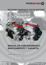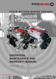
4 cylinders + 6 cylinders 4 cylinders + 6 cylinders - Steyr Motors
4 cylinders + 6 cylinders 4 cylinders + 6 cylinders - Steyr Motors
4 cylinders + 6 cylinders 4 cylinders + 6 cylinders - Steyr Motors

You also want an ePaper? Increase the reach of your titles
YUMPU automatically turns print PDFs into web optimized ePapers that Google loves.
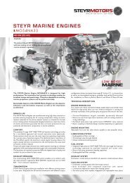
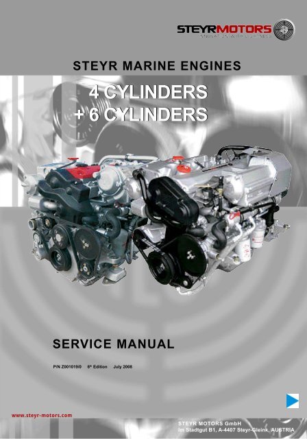
STEYR MARINE ENGINES<br />
4 CYLINDERS<br />
+ 6 CYLINDERS<br />
SERVICE MANUAL<br />
P/N Z001019/0 6 th Edition July 2008<br />
www.steyr-motors.com<br />
STEYR MOTORS GmbH<br />
Im Stadtgut B1, A-4407 <strong>Steyr</strong>-Gleink, AUSTRIA
THIS PAGE IS INTENTIONALLY BLANK
PREFACE<br />
STEYR MOTORS GmbH has developed high-performance diesel engines with modulated highpressure<br />
direct injection, especially for the marine environment. STEYR marine engines are designed to be<br />
adapted to various propulsion systems.<br />
This SERVICE MANUAL is published with the main intention -<br />
to provide information in form of technical data and know-how based on our experience in the marine diesel<br />
engine business, which will enable you in case of possible failure to operate, service and repair the engine<br />
4 & 6 CYLINDER MARINE<br />
ENGINES<br />
to maintain their operating safety and reliability.<br />
To achieve continuous improvement with regard to form and contents of the information required, we are<br />
assigned to your aid.<br />
We, therefore, would much appreciate your comment to the following questions -<br />
- Which descriptions or terms are not understandable<br />
- Which supplements or completions do you propose <br />
- Where did creep in contents-related mistakes <br />
Please address your comment to:<br />
STEYR MOTORS GmbH<br />
After Sales Service<br />
Im Stadtgut B1<br />
4407 STEYR<br />
AUSTRIA<br />
vom Inland:<br />
from home country<br />
07252/222/52<br />
07252/222/29<br />
vom Ausland<br />
from foreign<br />
countries:<br />
+43/7252/222/52<br />
+43/7252/222/29<br />
service@steyr-motors.com<br />
http://www.steyr-motors.com<br />
Z001019/0_6_July 2008
Repair and maintenance works on engine<br />
The descriptions and instructions in this technical documentation should support you in use and repair of our<br />
product. They refer to a specific equipment status of engine componets and accessories. Your individual<br />
engine may be equipped with other or less accessory.<br />
For any component not covered in this manual, please contact STEYR MOTORS GmbH, After Sales Service,<br />
as to respective documentation.<br />
This manual also contains specific references to your personal safety as user, as well as that of your<br />
customers, their passengers and other persons being close to the engine/boat.<br />
Product specifications, illustrations and technical data<br />
When reference is made in this manual to a brand name, product number, product or specific tool, an<br />
equivalent product may be used in place of the product or tool referred to, unless stated otherwise. To exclude<br />
possible danger, the operator has to provide for adequate safety precautions.<br />
All information, illustrations and specifications in this manual are based on the latest product data available at<br />
the time of printing. It cannot be guaranteed that this manual is constantly updated. Revised versions edited at<br />
a later date will replace all preceding editions.<br />
Illustrations in this manual may not always correspond to actual implements or components and are<br />
mainly intended as reference.<br />
STEYR MOTORS GmbH reserves the right to make changes at any time, without notice, on technical<br />
data or models and/or to discontinue models. The right is also reserved to change technical data or<br />
components at any time, without incurring any obligation to retrofit new parts on models produced<br />
prior to date of such change.<br />
To guarantee proper function of the engine and its attached parts after a repair, correct assembly is of<br />
utmost importance. Such works are to be carried out with greatest care, in accordance with repair<br />
instructions.<br />
WARRANTY:<br />
Warranty claims will expire if repair, service and operation of the engine do not<br />
correspond to the guidelines defined by STEYR MOTORS GmbH Please<br />
address your warranty claims, in accordance with warranty regulations, directly to<br />
the After Sales Service of STEYR MOTORS GmbH, <strong>Steyr</strong>.<br />
Every STEYR dealer is obliged to fill out the warranty registration card enclosed to every sold<br />
STEYR marine engine or every sold boat with a built-in STEYR marine engine.<br />
Part 1 (Warranty Registration Card) is to be handed over to the customer, part 2 (Dealer Record<br />
Card) remains with the dealer and part 3 is to be sent to the After Sales Service of STEYR<br />
MOTORS GmbH.<br />
This warranty registration card serves as a proof of ownership and is to be submitted in case<br />
of warranty claims.<br />
Every STEYR dealer is also obliged to carry out the Installation and pre-delivery inspection log.<br />
One copy (completely filled out) of this Installation and pre-delivery inspection log is to be sent<br />
to the After Sales Service of STEYR MOTORS GmbH.<br />
Z001019/0_6_July 2008
TABLE OF CONTENTS<br />
(MAIN ASSEMBLY GROUP ENGINE)<br />
GENERAL<br />
01 ENGINE<br />
02 COUPLING<br />
03 FUEL SYSTEM<br />
04 EXHAUST SYSTEM<br />
05 COOLING SYSTEM<br />
06 ELECTRICAL EQUIPMENT<br />
Z001019/0_6_July 2008
Components<br />
01<br />
Engine<br />
01.00<br />
Engine timing,<br />
engine mount<br />
01.01<br />
Cylinder block<br />
01.02<br />
Chrankshaft<br />
bearing,<br />
vibration damper<br />
01.03<br />
Flywheel,<br />
housing<br />
01.04<br />
Piston,<br />
connection rod<br />
01.05<br />
Chamshaft,<br />
housing,<br />
valve drive<br />
01.06<br />
Engine housing,<br />
oil pump,<br />
oil suction pipe<br />
01.08<br />
Intake manifold,<br />
intercooler<br />
01.09<br />
Auxiliary drive-PTO<br />
01.13<br />
Engine oil cooler,<br />
01.14<br />
Exhaust manifold,<br />
seals,<br />
heat exchanger<br />
02<br />
Coupling<br />
02.01<br />
Torsion coupling<br />
02.02<br />
Coupler<br />
02.03<br />
Torsion coupling<br />
Centa<br />
03<br />
Fuel system<br />
03.02<br />
Fuel pump,<br />
unit injector,<br />
pipes<br />
03.04<br />
Air filter<br />
03.05<br />
Turbo charger<br />
03.08<br />
Control solenoid<br />
03.09<br />
Fuel filter<br />
03.11<br />
Glow plugs<br />
04<br />
Exhaust system<br />
04.01<br />
Hi-riser<br />
Z001019/0_6_July 2008
05<br />
Cooling system<br />
05.01<br />
Cooler,<br />
heat exchanger,<br />
expansions tank<br />
05.03<br />
Pipes,<br />
thermostat<br />
05.04<br />
Coolant pump<br />
05.10<br />
Raw water pump,<br />
side mounted<br />
05.11<br />
Raw water pump,<br />
front mounted<br />
06<br />
Electrical<br />
system<br />
06.01<br />
Generator,<br />
alternator<br />
06.03<br />
Starter motor<br />
06.05<br />
Engine harness<br />
06.06<br />
EMS, E-box,<br />
diagnosis system,<br />
fuses<br />
06.07<br />
Instrument panel,<br />
connecting cable<br />
06.10<br />
Sender, sensor<br />
06.12<br />
Battery,<br />
charge equalization<br />
Z001019/0_6_July 2008
VERSIONS OF MANUAL<br />
Version Date Modification<br />
1.0 01. 10. 2000 new edition<br />
2.0 01. 06. 2002 release typ 164, 246<br />
3.0 01. 07. 2005 release typ 256<br />
4.0 01. 07. 2007 modification<br />
5.0 01. 03. 2008 modification<br />
6.0 01. 07. 2008 modification<br />
Z001019/0_6_July 2008
ToC<br />
SERVICE MANUAL MARINE ENGINES<br />
GENERAL<br />
Table of Contents<br />
GENERAL<br />
A General Remarks .................................................................................. 3<br />
A 1 Model and Serial Numbers ..................................................................... 3<br />
A 2 Documentation........................................................................................ 4<br />
A 3 Model summary ...................................................................................... 5<br />
A 3.1 Model summary 4 cylinder engines ........................................................ 5<br />
A 3.2 Model summary 6 cylinder engines ........................................................ 8<br />
A 4 Technical Data and Overview ................................................................. 12<br />
A 4.1 Technical Data and Overview 4 cylinder engines.................................... 12<br />
A 4.2 Technical Data and Overview 6 cylinder engines.................................... 16<br />
B Specifications ....................................................................................... 20<br />
B 1 Fuel Requirements ................................................................................. 20<br />
B 2 Motor oil .................................................................................................. 21<br />
C Maintenance and Service ..................................................................... 22<br />
C 1 Trouble Check Chart ............................................................................... 22<br />
C 2 Service- and Maintenance Schedule ...................................................... 24<br />
D General Information .............................................................................. 26<br />
D 1 Electronic Engine Management System (ECU) ...................................... 26<br />
D 2 Diagnostic System .................................................................................. 27<br />
D 3 Extended Storage Preservation Procedure............................................. 28<br />
D 4 Engine Break-in procedure ...................................................................... 32<br />
D 5 Operation after Break-in .......................................................................... 34<br />
E Quality Gudelines for Repair ................................................................ 36<br />
E 1 Spare parts specification ......................................................................... 36<br />
E 2 Workshop profile ..................................................................................... 36<br />
E 3 Nomenclature .......................................................................................... 37<br />
E 4 SI - System .............................................................................................. 38<br />
E 5 Abbreviations .......................................................................................... 39<br />
F Operating material and Information on Disposal................................ 40<br />
F 1 List of operating material ......................................................................... 40<br />
F 2 Disposal of automotive waste products .................................................... 41<br />
G Notes on Safety..................................................................................... 42<br />
G 1 General notes on safety ........................................................................... 42<br />
G 2 Guidelines for damage prevention ........................................................... 42<br />
G 3 Legal rules ............................................................................................... 42<br />
G 4 Safety in the use of operating material ..................................................... 43<br />
Z001019/0_8_Octobre 2011<br />
Page GENERAL-1
ToC<br />
GENERAL<br />
SERVICE MANUAL MARINE ENGINES<br />
G 5 Measures in case of accidents ................................................................ 43<br />
H Thightening Torques ............................................................................ 44<br />
H 1 Listing of Thightening Torques.................................................................. 44<br />
H 2 General Tightening torques ...................................................................... 49<br />
H 3 Testing of torque wrench .......................................................................... 50<br />
H 4 Non-destructive material testing ............................................................... 50<br />
H 5 Use of adhesive and sealing materials..................................................... 50<br />
H 6 Solvent-free sealing materials .................................................................. 50<br />
J Wear Limits ............................................................................................ 52<br />
J 1 Adjustment information for service and maintenance ................................ 53<br />
Page GENERAL-2 Z001019/0_8_Octobre 2011
ToC<br />
SERVICE MANUAL MARINE ENGINES<br />
GENERAL<br />
A<br />
A 1<br />
GENERAL REMARKS<br />
Model and Serial Numbers<br />
The primary model and serial number (ill.1 or ill.2) is<br />
located on the engine as illustrated.<br />
These numbers are required for warranty<br />
claims and ordering parts.<br />
FOR ALL<br />
4 CYL. MARINE ENGINES<br />
FOR ALL<br />
6 CYL. MARINE ENGINES<br />
1<br />
1<br />
01.01 ill.1<br />
08006<br />
01.01 ill.2<br />
08007<br />
The model and serial number of the marine gearbox<br />
is located on the marine gearbox housing as illustrated.<br />
To obtain instructions regarding marine gearbox<br />
operation, refer to marine gearbox owners manual.<br />
17<br />
01.01 ill.3<br />
06014<br />
Z001019/0_8_Octobre 2011<br />
Page GENERAL-3
ToC<br />
GENERAL<br />
A 2 Documentation 4 and 6 cylinder<br />
SERVICE MANUAL MARINE ENGINES<br />
The following documentation is available in English language on our website:<br />
http://www.steyr-motors.com/technical<br />
technical documentation on CD - ROM P/N Z 001009/0<br />
operation-, maintenance & warranty manual<br />
for all marine engines P/N Z 001022/0<br />
tool catalogue for all marine engines P/N Z 001002/1<br />
spare parts catalogue STEYR 94 td diesel marine P/N Z 001023/0<br />
STEYR 144 vti/td diesel marine P/N Z 001005/0<br />
STEYR 164 td diesel marine P/N Z 001015/0<br />
STEYR 174 vti diesel marine P/N Z 001011/0<br />
STEYR 166 td diesel marine P/N Z 011796/1<br />
STEYR 236 FDE P/N Z 011796/0<br />
STEYR 236 td diesel marine P/N Z 011796/1 - Z011769/2<br />
STEYR 246 td diesel marine P/N Z 011800/0<br />
STEYR 256 td diesel marine P/N Z 011810/0<br />
STEYR 266 td diesel marine P/N Z 011805/0<br />
installation manual for marine engines P/N Z 001007/0<br />
service manual for all marine engines P/N Z 001019/0<br />
operator's manual marine gear ZF P/N Z 001003/0<br />
Diagrams marine engine functions on CD P/N Z 001021/0<br />
Page GENERAL-4 Z001019/0_8_Octobre 2011
ToC<br />
SERVICE MANUAL MARINE ENGINES<br />
A 3 Modell summary<br />
GENERAL<br />
A 3.1 Modell summary 4 cylinder engines<br />
Bobtail - Version<br />
03.01 ill.1<br />
Equipment:<br />
with side mounted raw water<br />
pump or,<br />
with side mounted raw water<br />
pump, power steering pump<br />
Inborder i.e. ZF 45 Marinegear<br />
Down angle<br />
03.01 ill.2<br />
Innenborder i.e. ZF 63 Marinegear<br />
03.01 ill.3<br />
Z001019/0_8_Octobre 2011<br />
Page GENERAL-5
ToC<br />
GENERAL<br />
SERVICE MANUAL MARINE ENGINES<br />
Lifeboat Engine<br />
Equipment<br />
Bobtail "B"<br />
03.01 ill.4<br />
Direkt gearbox<br />
03.01 ill.5<br />
A-down angle gear box<br />
03.01 ill.6<br />
Parallel offset gearbox<br />
03.01 ill.7<br />
Page GENERAL-6 Z001019/0_8_Octobre 2011
ToC<br />
SERVICE MANUAL MARINE ENGINES<br />
GENERAL<br />
Jet Drive<br />
TYPE<br />
Alamarin<br />
Hamilton<br />
03.01 ill.8<br />
Castoldi<br />
03.01 ill.9<br />
03.01 ill.10<br />
Stern Drive<br />
TYPE<br />
Mercury Alpha Bravo I, II & III<br />
Volvo DP 290<br />
Volvo DP 290 Hydraulic<br />
03.01 ill.11<br />
SX - Stern Drive<br />
Z001019/0_8_Octobre 2011<br />
Page GENERAL-7
ToC<br />
GENERAL<br />
A 3.2 Modell summary 6 cylinder engines<br />
Bobtail - Version<br />
SERVICE MANUAL MARINE ENGINES<br />
with side mounted raw water<br />
pump or,<br />
with side mounted raw water<br />
pump, power steering pump<br />
and front mounted auxiliary<br />
drive-PTO<br />
03.02 ill.1<br />
Inborder i.e. ZF 63 Marine gear<br />
Down angle<br />
03.02 ill.2<br />
03.02 ill.3<br />
Page GENERAL-8 Z001019/0_8_Octobre 2011
ToC<br />
SERVICE MANUAL MARINE ENGINES<br />
GENERAL<br />
Transmission<br />
i = 2.5V, shaft angle 12°<br />
i = 2.0V, shaft angle 12°<br />
03.02 ill.4<br />
Lifeboat Engine<br />
Equipment<br />
Bobtail "B"<br />
03.02 ill.5<br />
Direkt gearbox<br />
03.02 ill.6<br />
A-down angle gear box<br />
03.02 ill.7<br />
Parallel offset gearbox<br />
03.02 ill.8<br />
Z001019/0_8_Octobre 2011<br />
Page GENERAL-9
ToC<br />
GENERAL<br />
SERVICE MANUAL MARINE ENGINES<br />
Jet drive<br />
03.02 ill.9<br />
Jet Drive<br />
TYPE<br />
Alamarin<br />
Hamilton<br />
03.02 ill.10<br />
Castoldi<br />
03.02 ill.11<br />
Stern drive<br />
Type<br />
Mercury Bravo II & III<br />
Volvo DP 290<br />
Stern Power Drive<br />
03.02 ill.12<br />
Volvo DP 290 ZF<br />
Hydraulic Pump<br />
Volvo SX - Drive<br />
King Cobra Drive<br />
Page GENERAL-10 Z001019/0_8_Octobre 2011
ToC<br />
SERVICE MANUAL MARINE ENGINES<br />
GENERAL<br />
THIS PAGE IS INTENTIONALLY BLANK<br />
Z001019/0_8_Octobre 2011<br />
Page GENERAL-11
ToC<br />
GENERAL<br />
A 4.1<br />
MAKE<br />
Technical data and overview 4 cylinder engines<br />
STEYR M 14 TCM, TCAM<br />
SERVICE MANUAL MARINE ENGINES<br />
type MO84K32 MO94K33 MO114K33 MO144V38<br />
displacement<br />
piston displacement<br />
rated power acc. EN ISO 8665:2006<br />
(impeller **) KW / HP<br />
Jet - Drive / Inboard<br />
Z - Drive<br />
number of <strong>cylinders</strong><br />
2133 cm³<br />
85,0 x 94,0 mm<br />
53 / 71<br />
52 / 70<br />
64 / 86<br />
63 / 84<br />
78 / 105<br />
77 / 104<br />
103 / 138<br />
101 / 136<br />
4-cylinder in-line engine (position of cyl. 1 at vibration damper side)<br />
ignition order 1 - 3 - 4 - 2<br />
sense of rotation, seen from front<br />
right<br />
compression ratio 17,5 : 1<br />
full-load speed range (rpm) 3000 - 3200 3050 - 3800 3200 - 3800 3600 - 3800<br />
idle speed<br />
injection<br />
fuel<br />
650 rpm. (adjustable)<br />
pump - nozzle with modelling needle control<br />
and electronic control<br />
acc. to CEC RF-03-A-84 (DIN EN 590) Cetan >49; diesel fuel<br />
No. 2-D, temperature above -7°C; No.1-D, temperature below -7°C<br />
fuel filter P/No. 2203710/0<br />
fuel filter location<br />
intake-sided<br />
air filter P/No. 2178992/0<br />
oil pressure above 2000 rpm.<br />
filling capacity motor oil<br />
400 - 700 kPa (60 - 100 PSI) microprocessor controlled<br />
approx. 8,0 l engine housing (incl. approx. 1 l oil filter contents)<br />
specification motor oil SAE 5W-50/ACEA B4-02/API CF or 10W-40/ACEA, E4, E5, E7,<br />
API CF / P/N0. Z010058/0<br />
oil and oil filter change intervals*)<br />
every 150 operating hours and/or once per season<br />
oil filter P/No. 2178582/1<br />
oil filter location<br />
electric charging system<br />
cooling system<br />
coolant capacity<br />
pressure-sided<br />
14 V / 90 A alternator with transistorized voltage regulator<br />
dual cooling circuit; thermostat-controlled, pressurized cooling<br />
circuit; circulating pump with heat exchanger on engine; governor<br />
pump, external raw water circuit to heat exchanger<br />
11,5 liters<br />
coolant STEYR MOTORS engine coolant - 36 C°<br />
P/No. Z011785/0<br />
*) extended periods to be evaluated upon application and type of usage<br />
STEYR MOTORS GmbH. reserves the right to make changes without notice or obligations.<br />
**) Efficiency of gearbox = 97,0%, efficiency of Z-drive = 95,5%<br />
Page GENERAL-12 Z001019/0_8_Octobre 2011
ToC<br />
SERVICE MANUAL MARINE ENGINES<br />
GENERAL<br />
Overview for all STEYR 4 Cyl. Marine Engines<br />
Item<br />
Designation<br />
1 Zinc Anode (4 Units)<br />
2 Model and Serial Number<br />
3 Intercooler<br />
4 Fuel/Oil Cooler with Raw Water Drain Plug<br />
5 Fuel Pump<br />
6 Oil Seperator<br />
7 Raw Water Drain Plug<br />
8 Valve Crankshaft Housing Ventilation<br />
(only SOLAS)<br />
9 Oil Drain Plug<br />
10 Fuel Filter<br />
11 Oil Filter<br />
12 Hydraulic Pump<br />
13 Raw Water Inlet Fitting<br />
14 Raw Water Pump<br />
15 Coolant Drain Plug (2 Units)<br />
16 Engine Oilcooler<br />
17 Oil Suction Pipe<br />
18 Oil Dipstick<br />
19 Hydraulic Oil Tank<br />
20 Cooler Cap<br />
21 Potentiometer Accelerator<br />
22 Motor Oil Filler Cap<br />
23 Boost Pressure Sensor<br />
24 Rack Position Sensor *)<br />
25 Drive Belt<br />
26 Cover T-Belt, Lower<br />
27 Engine Mount<br />
28 Drive Belt Tensioner<br />
29 Vibration Damper<br />
30 Cover T-Belt, Upper<br />
31 Engine Lifting Eye<br />
32 Speed Sensor<br />
33 Valve Cover<br />
34 Heat Exchanger<br />
35 Coolant Expansion Tank<br />
36 Diagnostic Outlet<br />
37 Inversion Switch (only for SOLAS)<br />
38 Connector Instrument Panel<br />
39 Coolant Temperature Sensor<br />
40 Thermostat Housing<br />
41 Alternator<br />
42 Circuit Breakers<br />
43 Engine Management System/Fuses<br />
44 Exhaust Temperature Sensor<br />
45 Air Filter<br />
46 Turbo Charger<br />
47 Exhaust Elbow<br />
48 Starter Relais (Backside E-Box Ground Plate)<br />
49 Starter Motor<br />
50 Flywheel<br />
51 Flywheel Housing<br />
52 Oil Pressure Sensor<br />
19<br />
18<br />
17<br />
16<br />
15<br />
14<br />
13<br />
12<br />
11<br />
20<br />
31<br />
30<br />
29<br />
28<br />
44<br />
43<br />
45<br />
52<br />
51<br />
50<br />
1 2 3 4 5 6<br />
10 9<br />
1 32 33 34 35 36 37<br />
38<br />
39<br />
1<br />
7<br />
8<br />
06001<br />
21<br />
22<br />
23<br />
24<br />
25<br />
26<br />
27<br />
06002<br />
1<br />
15<br />
40<br />
41<br />
42<br />
06003<br />
46<br />
47<br />
48<br />
49<br />
06004<br />
*) This sensor is magnetism sensitive. All external magnets must be kept away.<br />
Z001019/0_8_Octobre 2011<br />
Page GENERAL-13
ToC<br />
GENERAL<br />
SERVICE MANUAL MARINE ENGINES<br />
MAKE<br />
STEYR M 14 TCAM<br />
type MO144M38 MO164M40<br />
displacement<br />
piston displacement<br />
rated power acc. EN ISO 8665:2006<br />
(impeller **) KW / HP<br />
Jet - Drive / Inboard<br />
Z - Drive<br />
number of <strong>cylinders</strong><br />
2133 cm³<br />
85,0 x 94,0 mm<br />
103 / 138<br />
101 / 136<br />
116 / 156<br />
114 / 154<br />
4-cylinder in-line engine (position of cyl. 1 at vibration damper side)<br />
ignition order 1 - 3 - 4 - 2<br />
sense of rotation, seen from front<br />
right<br />
compression ratio 17,5 : 1<br />
full-load speed range (rpm) 3700 - 3900 3800 - 4000<br />
idle speed<br />
injection<br />
fuel<br />
650 rpm. (adjustable)<br />
pump - nozzle with modelling needle control<br />
and electronic control<br />
acc. to CEC RF-03-A-84 (DIN EN 590) Cetan >49; diesel fuel<br />
No. 2-D, temperature above -7°C; No.1-D, temperature below -7°C<br />
fuel filter P/No. 2203710/0<br />
fuel filter location<br />
intake-sided<br />
air filter P/No. 2178992/0<br />
oil pressure above 2000 rpm.<br />
filling capacity motor oil<br />
400 - 700 kPa (60 - 100 PSI) microprocessor controlled<br />
approx. 8,0 l engine housing (incl. approx. 1 l oil filter contents)<br />
specification motor oil SAE 5W-50/ACEA B4-02/API CF or 10W-40/ACEA, E4, E5, E7,<br />
API CF / P/N0. Z010058/0<br />
oil and oil filter change intervals*)<br />
every 150 operating hours and/or once per season<br />
oil filter P/No. 2178582/1<br />
oil filter location<br />
electric charging system<br />
cooling system<br />
coolant capacity<br />
pressure-sided<br />
14 V / 90 A alternator with transistorized voltage regulator<br />
dual cooling circuit; thermostat-controlled, pressurized cooling<br />
circuit; circulating pump with heat exchanger on engine; governor<br />
pump, external raw water circuit to heat exchanger<br />
11,5 liters<br />
coolant STEYR MOTORS engine coolant - 36 C°<br />
P/No. Z011785/0<br />
*) extended periods to be evaluated upon application and type of usage<br />
STEYR MOTORS GmbH. reserves the right to make changes without notice or obligations.<br />
**) Efficiency of gearbox = 97,0%, efficiency of Z-drive = 95,5%<br />
Page GENERAL-14 Z001019/0_8_Octobre 2011
ToC<br />
SERVICE MANUAL MARINE ENGINES<br />
GENERAL<br />
Overview for all STEYR 4 Cyl. Marine Engines<br />
Item<br />
Designation<br />
1 Zinc Anode (4 Units)<br />
2 Model and Serial Number<br />
3 Intercooler<br />
4 Fuel/Oil Cooler with Raw Water Drain Plug<br />
5 Fuel Pump<br />
6 Oil Seperator<br />
7 Raw Water Drain Plug<br />
8 Valve Crankshaft Housing Ventilation<br />
(only SOLAS)<br />
9 Oil Drain Plug<br />
10 Fuel Filter<br />
11 Oil Filter<br />
12 Hydraulic Pump<br />
13 Raw Water Inlet Fitting<br />
14 Raw Water Pump<br />
15 Coolant Drain Plug (2 Units)<br />
16 Engine Oilcooler<br />
17 Oil Suction Pipe<br />
18 Oil Dipstick<br />
19 Hydraulic Oil Tank<br />
20 Cooler Cap<br />
21 Potentiometer Accelerator<br />
22 Motor Oil Filler Cap<br />
23 Boost Pressure Sensor<br />
24 Rack Position Sensor *)<br />
25 Drive Belt<br />
26 Cover T-Belt, Lower<br />
27 Engine Mount<br />
28 Drive Belt Tensioner<br />
29 Vibration Damper<br />
30 Cover T-Belt, Upper<br />
31 Engine Lifting Eye<br />
32 Speed Sensor<br />
33 Valve Cover<br />
34 Heat Exchanger<br />
35 Coolant Expansion Tank<br />
36 Diagnostic Outlet<br />
37 Inversion Switch (only for SOLAS)<br />
38 Connector Instrument Panel<br />
39 Coolant Temperature Sensor<br />
40 Thermostat Housing<br />
41 Alternator<br />
42 Circuit Breakers<br />
43 Engine Management System/Fuses<br />
44 Exhaust Temperature Sensor<br />
45 Air Filter<br />
46 Turbo Charger<br />
47 Exhaust Elbow<br />
48 Starter Relais (Backside E-Box Ground Plate)<br />
49 Starter Motor<br />
50 Flywheel<br />
51 Flywheel Housing<br />
52 Oil Pressure Sensor<br />
19<br />
18<br />
17<br />
16<br />
15<br />
14<br />
13<br />
12<br />
11<br />
20<br />
31<br />
30<br />
29<br />
28<br />
44<br />
43<br />
45<br />
52<br />
51<br />
50<br />
1 2 3 4 5 6<br />
10 9<br />
1 32 33 34 35 36 37<br />
38<br />
39<br />
1<br />
7<br />
8<br />
06001<br />
21<br />
22<br />
23<br />
24<br />
25<br />
26<br />
27<br />
06002<br />
1<br />
15<br />
40<br />
41<br />
42<br />
06003<br />
46<br />
47<br />
48<br />
49<br />
06004<br />
*) This sensor is magnetism sensitive. All external magnets must be kept away.<br />
Z001019/0_8_Octobre 2011<br />
Page GENERAL-15
ToC<br />
GENERAL<br />
A 4.2<br />
Technical data and overview 6 cylinder engines<br />
SERVICE MANUAL MARINE ENGINES<br />
MAKE<br />
STEYR M 16 TCM, TCAM<br />
type MO126M28 MO166K28 MO196K35 MO236K42<br />
displacement<br />
piston displacement<br />
rated power acc. EN ISO 8665:2006<br />
(impeller **) KW / HP<br />
Jet - Drive / Inboard<br />
Z - Drive<br />
number of <strong>cylinders</strong><br />
3200 cm³<br />
85,0 x 94,0 mm<br />
87 / 117<br />
86 / 115<br />
116 / 156<br />
115 / 154<br />
136 / 182<br />
134 / 179<br />
165 / 221<br />
162 / 218<br />
6-cylinder in-line engine (position of cyl. 1 at vibration damper side)<br />
ignition order 1 - 5 - 3 - 6 -2 - 4<br />
sense of rotation, seen from front<br />
right<br />
compression ratio 17,5 : 1<br />
full-load speed range (rpm) 2600 - 2800 2600 - 2800 3300 - 3500 4000 - 4300<br />
idle speed<br />
injection<br />
fuel<br />
630 rpm. (adjustable)<br />
pump - nozzle with modelling needle control<br />
and electronic control<br />
acc. to CEC RF-03-A-84 (DIN EN 590) Cetan >49; diesel fuel<br />
No. 2-D, temperature above -7°C; No.1-D, temperature below -7°C<br />
fuel filter P/No. 2177745/1<br />
fuel filter location<br />
suction-sided<br />
air filter MO126 - P/No. 2178992/0; all other 6 Cyl. - P/N 2178992/1<br />
oil pressure above 2000 rpm.<br />
filling capacity motor oil<br />
400 - 700 kPa (60 - 100 PSI) microprocessor controlled<br />
approx. 10,0 l engine housing (incl. approx. 1 l oil filter contents)<br />
specification motor oil SAE 5W-50/ACEA B4-02/API CF or 10W-40/ACEA, E4, E5, E7,<br />
API CF / P/N0. Z010058/0<br />
oil and oil filter change intervals*)<br />
every 150 operating hours and/or once per season<br />
oil filter P/No. 2178582/1<br />
oil filter location<br />
electric charging system<br />
cooling system<br />
coolant capacity<br />
suction-sided<br />
14 V / 90 A alternator with transistorized voltage regulator<br />
dual cooling circuit; thermostat-controlled, pressurized cooling<br />
circuit; circulating pump with heat exchanger on engine; governor<br />
pump, external raw water circuit to heat exchanger<br />
13,2 liters<br />
coolant STEYR MOTORS engine coolant - 36 C°<br />
P/No. Z011785/0<br />
*) extended periods to be evaluated upon application and type of usage<br />
STEYR MOTORS GmbH. reserves the right to make changes without notice or obligations.<br />
**) Efficiency of gearbox = 97,0%, efficiency of Z-drive = 95,5%<br />
Page GENERAL-16 Z001019/0_8_Octobre 2011
ToC<br />
SERVICE MANUAL MARINE ENGINES<br />
GENERAL<br />
Overview STEYR MO126M28, MO166K28, MO196K35, MO236K42<br />
Item<br />
Designation<br />
18<br />
1 2 3 4 5 6 7 2<br />
1 Boost Pressure Sensor<br />
2 Zinc Anode (5 Units)<br />
3 Intercooler<br />
4 Fuel- / Hydr. Oil Cooler<br />
5 Engine Oilcooler<br />
6 Model and Serial Number<br />
7 Oil Seperator<br />
8 Raw Water Drain Plug<br />
9 Valve Crankshaft Housing Ventilation<br />
(only SOLAS)<br />
10 Fuel Filter<br />
11 Fuel Pump<br />
12 Oil Filter<br />
13 Raw Water Inlet Fitting<br />
14 Raw Water Pump<br />
15 Coolant Drain Plug (2 Units)<br />
16 Oil Suction Pipe<br />
17 Oil Dipstick<br />
18 Rack Position Sensor *)<br />
19 Engine Lifting Eye<br />
20 Motor Oil Filler Cap<br />
21 Potentiometer Accelerator<br />
22 Drive Belt, Raw Water Pump<br />
23 Engine Mount<br />
24 Drive Belt Tensioner<br />
25 Cover T-Belt, Lower<br />
26 Vibration Damper<br />
27 Drive Belt, Alternator & Hydr: Pump<br />
28 Speed Sensor<br />
29 Cover T-Belt, Upper<br />
30 Valve Cover<br />
31 Heat Exchanger<br />
32 Coolant Expansion Tank<br />
33 Cooler Cap<br />
34 Diagnostic Outlet<br />
35 Inversion Switch (only for SOLAS)<br />
36 Connector Instrument Panel<br />
37 Coolant Temperature Sensor<br />
38 Thermostat Housing<br />
39 Hydraulic Oil Tank<br />
40 Circuit Breakers<br />
41 Alternator<br />
42 Hydraulic Pump<br />
43 Oil Drain Plug<br />
44 Starter Motor<br />
45 Engine Management System/Fuses<br />
46 Exhaust Temperature Sensor<br />
47 Air Filter<br />
48 Turbo Charger<br />
49 Exhaust Elbow<br />
50 Starter Relais (Backside E-Box Ground Plate)<br />
51 Flywheel<br />
52 Flywheel Housing<br />
53 Oil Pressure Sensor<br />
*) This sensor is magnetism sensitive. All external magnets must be kept away.<br />
17<br />
16<br />
15<br />
46<br />
45<br />
44<br />
29<br />
28<br />
27<br />
14<br />
13<br />
12<br />
19 20 21<br />
26<br />
25<br />
22<br />
23<br />
24<br />
8<br />
9<br />
10<br />
11<br />
06032<br />
06033<br />
2 30 31 32 33 34 35 36 37<br />
43<br />
47 48 49<br />
53<br />
52<br />
2<br />
50<br />
51<br />
2<br />
15<br />
38<br />
39<br />
40<br />
41<br />
42<br />
06034<br />
06035<br />
Z001019/0_8_Octobre 2011<br />
Page GENERAL-17
ToC<br />
GENERAL<br />
SERVICE MANUAL MARINE ENGINES<br />
MAKE<br />
STEYR M 16 TCAM<br />
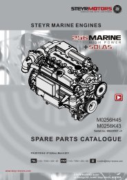
type MO256K43 MO256H45<br />
displacement<br />
piston displacement<br />
rated power acc. EN ISO 8665:2006<br />
(impeller **) KW / HP<br />
Jet - Drive / Inboard<br />
Z - Drive<br />
number of <strong>cylinders</strong><br />
3200 cm³<br />
85,0 x 94,0 mm<br />
178 / 239<br />
176 / 236<br />
178 / 239<br />
176 / 236<br />
6-cylinder in-line engine (position of cyl. 1 at vibration damper side)<br />
ignition order 1 - 5 - 3 - 6 -2 - 4<br />
sense of rotation, seen from front<br />
right<br />
compression ratio 17,5 : 1<br />
full-load speed range (rpm) 4000 - 4300 4000 - 4500<br />
idle speed<br />
injection<br />
fuel<br />
630 rpm. (adjustable)<br />
pump - nozzle with modelling needle control<br />
and electronic control<br />
acc. to CEC RF-03-A-84 (DIN EN 590) Cetan >49; diesel fuel<br />
No. 2-D, temperature above -7°C; No.1-D, temperature below -7°C<br />
fuel filter P/No. 2178992/1<br />
fuel filter location<br />
suction-sided<br />
air filter P/No. 2178992/0 P/No.2178992/1<br />
oil pressure above 2000 rpm.<br />
filling capacity motor oil<br />
400 - 700 kPa (60 - 100 PSI) microprocessor controlled<br />
approx. 10,0 l engine housing (incl. approx. 1 l oil filter contents)<br />
specification motor oil SAE 5W-50/ACEA B4-02/API CF or 10W-40/ACEA, E4, E5, E7,<br />
API CF / P/N0. Z010058/0<br />
oil and oil filter change intervals*)<br />
every 150 operating hours and/or once per season<br />
oil filter P/No. 2178582/1<br />
oil filter location<br />
electric charging system<br />
cooling system<br />
coolant capacity<br />
suction-sided<br />
14 V / 90 A alternator with transistorized voltage regulator<br />
dual cooling circuit; thermostat-controlled, pressurized cooling<br />
circuit; circulating pump with heat exchanger on engine; governor<br />
pump, external raw water circuit to heat exchanger<br />
13,2 liters<br />
coolant STEYR MOTORS engine coolant - 36 C°<br />
P/No. Z011785/0<br />
*) extended periods to be evaluated upon application and type of usage<br />
STEYR MOTORS GmbH. reserves the right to make changes without notice or obligations.<br />
**) Efficiency of gearbox = 97,0%, efficiency of Z-drive = 95,5%<br />
Page GENERAL-18 Z001019/0_8_Octobre 2011
ToC<br />
SERVICE MANUAL MARINE ENGINES<br />
Overview STEYR MO256K43, MO256H45<br />
GENERAL<br />
Item<br />
Designation<br />
17<br />
1 2 3 4 5 6 2<br />
1 Boost Pressure Sensor<br />
2 Zinc Anode (5 Units)<br />
3 Intercooler<br />
4 Engine Oil / Fuel / Hydr. Oil Cooler<br />
5 Model and Serial Number<br />
6 Oil Seperator<br />
7 Raw Water Drain Plug<br />
8 Valve Crankshaft Housing Ventilation (only<br />
SOLAS)<br />
9 Fuel Filter<br />
10 Fuel Pump<br />
11 Oil Filter<br />
12 Raw Water Inlet Fitting<br />
13 Raw Water Pump<br />
14 Coolant Drain Plug (2 Units)<br />
15 Oil Suction Pipe<br />
16 Oil Dipstick<br />
17 Rack Position Sensor *)<br />
18 Engine Lifting Eye<br />
19 Motor Oil Filler Cap<br />
20 Potentiometer Accelerator<br />
21 Drive Belt, Raw Water Pump<br />
22 Engine Mount<br />
23 Drive Belt Tensioner<br />
24 Cover T-Belt, Lower<br />
25 Vibration Damper<br />
26 Drive Belt, Alternator & Hydr: Pump<br />
27 Speed Sensor<br />
28 Cover T-Belt, Upper<br />
29 Valve Cover<br />
30 Heat Exchanger<br />
31 Coolant Expansion Tank<br />
32 Cooler Cap<br />
33 Diagnostic Outlet<br />
34 Inversion Switch (only for SOLAS)<br />
35 Connector Instrument Panel<br />
36 Coolant Temperature Sensor<br />
37 Thermostat Housing<br />
38 Hydraulic Oil Tank<br />
39 Circuit Breakers<br />
40 Alternator<br />
41 Hydraulic Pump<br />
42 Oil Drain Plug<br />
43 Starter Motor<br />
44 Engine Management System/Fuses<br />
45 Exhaust Temperature Sensor<br />
46 Air Filter<br />
47 Turbo Charger<br />
48 Exhaust Elbow<br />
49 Starter Relais (Backside E-Box Ground Plate)<br />
50 Flywheel<br />
51 Flywheel Housing<br />
52 Oil Pressure Sensor<br />
16<br />
15<br />
14<br />
45<br />
44<br />
43<br />
28<br />
27<br />
26<br />
13<br />
12<br />
11<br />
18 19 20<br />
25<br />
24<br />
21<br />
22<br />
23<br />
7<br />
8<br />
9<br />
10<br />
06028<br />
06029<br />
2 29 30 31 32 33 34 35 36<br />
42<br />
46 47 48<br />
52<br />
51<br />
2<br />
49<br />
50<br />
2<br />
14<br />
37<br />
38<br />
39<br />
40<br />
41<br />
06030<br />
06031<br />
*) This sensor is magnetism sensitive. All external magnets must be kept away.<br />
Z001019/0_8_Octobre 2011<br />
Page GENERAL-19
ToC<br />
GENERAL<br />
SERVICE MANUAL MARINE ENGINES<br />
B<br />
Specifications<br />
B 1 Fuel Requirements<br />
The STEYR Marine Engines are designed for maximum fuel economy. To maintain optimum performance use<br />
diesel fuel according to CEC RF-03-A-84 or equivalent to meet this specification. When temperatures are below<br />
-7° C (20° F), use diesel fuels with additives for low temperature operation.<br />
How to Select Fuel Oil<br />
Fuel quality is an important factor in obtaining satisfactory engine performance, long engine life, and acceptable<br />
exhaust emission levels. Direct injected diesel engines are designed to operate on most diesel fuels marketed<br />
today. In general, fuels meeting the properties of CEC RF-03-A-84 have provided satisfactory performance.<br />
The ASTM D 975 specification, however, does not in itself adequately define the fuel characteristics needed for<br />
assurance of fuel quality. The properties listed in the following fuel oil selection chart have provided optimum engine<br />
performance.<br />
Fuel Oil Selection Chart<br />
General<br />
Fuel classification<br />
CEC RF-03-A-84<br />
Limit value and<br />
units<br />
CEC RF-03-A-80<br />
Limit value and<br />
units<br />
ASTM -<br />
Test procedure<br />
Cetane number<br />
min. 49 - max. 53<br />
min. 51 - max. 57<br />
D 613 (D 976)<br />
Gravity at 15°C (kg/l)<br />
min. 0,835<br />
max. 0845<br />
min. 0,835<br />
max. 0845<br />
D 1298<br />
Destillation<br />
50%<br />
90%<br />
min. 245°C<br />
min. 320°C<br />
max. 340°C<br />
min. 245°C<br />
min. 320°C<br />
max. 340°C<br />
D86<br />
End point<br />
max. 370°C<br />
max. 370°C<br />
Flash point<br />
min. 55°C<br />
min. 55°C<br />
D 93<br />
CFPP (Cloud point)<br />
min. -- / max. -5°c<br />
max. -5°c<br />
EN 116 (CEN)<br />
Viscosity Kinematic 40°C<br />
min. 2,5 mm²/s<br />
max. 3,5 mm²/s<br />
min. 2,5 mm²/s<br />
max. 3,5 mm²/s<br />
D 445<br />
Sulfur content<br />
max. 0,3 mass-%<br />
max. 0,50 mass-%<br />
D 1266/D 2622<br />
D 2785<br />
Cupper corrosion<br />
max. 1<br />
max. 1<br />
D 130<br />
Carbon residue<br />
Conradson number (10% residue)<br />
max. 0,2 mass-%<br />
max. 0,2 mass-%<br />
D 189<br />
Ash<br />
max. 0,01 mass-%<br />
max. 0,01 mass-%<br />
D 482<br />
Water content<br />
max. 0,05 mass-%<br />
max. 0,05 mass-%<br />
D 95/D 1744<br />
Acid content (strong acid)<br />
max. 0,20 mg KOH/g<br />
max. 0,20 mg KOH/g<br />
D 974<br />
Oxidation stability<br />
max.2,5 mg/100ml<br />
max.2,5 mg/100ml<br />
D 2274<br />
Page GENERAL-20 Z001019/0_8_Octobre 2011
ToC<br />
SERVICE MANUAL MARINE ENGINES<br />
GENERAL<br />
B 2<br />
Motor oil<br />
To obtain the best engine performance and engine life, only motor oils of know manufacturers are to be used,<br />
with ACEA, API service code and specified SAE viscosity. Refer to oil identification symbol on the container.<br />
Initial filling quantity: 4 Cyl. engines 8,4 Litre (Oil filling, incl. 1l oil filter)<br />
6 Cyl engines 10,4 Litre (Oil filling, incl. 1l oil filter)<br />
Oil quantity between MIN. and MAX.<br />
on dipstick<br />
2,0 Litre<br />
Oil change quantity: 4 Cyl. engines 7,0 Liter (without oil filter)<br />
6 Cyl. engines 9,0 Liter (without oil filter)<br />
Öil filter:<br />
ca. 1 Litre<br />
Oil - specification, Minimum: API: CF or higher<br />
ACEA:<br />
B4 - 02 or higher<br />
Viscosity class: SYNTHETIC OIL 5W-50<br />
SYNTHETIC OIL 10W-40<br />
Recommended<br />
engine oil: STEYR TURBO DIESEL ENGINE OIL - SAE 10W-40<br />
SMO No. Z010058/0<br />
Initial factory fill is a high quality break-in oil specified ACEA B4 - 02, SAE 5W-50. During the break<br />
in period (20 hours), frequently check the oil level. Somewhat higher oil consumption is normal until piston rings<br />
are seated. The oil level should be maintained between the minimum and maximum marks on the dipstick. The<br />
space between the marks represents approximately 2 quarts (2 litres). For oil dipstick location, refer to<br />
section Technical Data and Overview (A 4)<br />
Refer to Service and Maintenance Chart (C 2) for<br />
recommended oil change intervals.<br />
FOR HEAVY DUTY<br />
DIESEL ENGINES<br />
Oil Identification Symbol<br />
Motor oils are specified by ACEA, API<br />
service code and SAE viscosity numbers.<br />
These may be found on the label, top of can, or oil<br />
identification symbol.<br />
NOTE:<br />
Some motor oils have several ACEA / API quality<br />
ratings.<br />
The recommended ACEA /API service letter code<br />
must be among these quality ratings.<br />
02.02 ill.1<br />
ACEA E7 or B4 - 02<br />
ACEA E7 or B4-02<br />
API CF<br />
ill.1 Top of Can<br />
ill.2 Oil Identification Symbol<br />
SAE<br />
5 W-50<br />
10 W-40<br />
02.02 ill.2<br />
API<br />
SERVICE CODE<br />
CF<br />
Z001019/0_8_Octobre 2011<br />
Page GENERAL-21
ToC<br />
GENERAL<br />
SERVICE MANUAL MARINE ENGINES<br />
C<br />
C 1<br />
Maintenance and Service<br />
Trouble Check Chart<br />
ATTENTION:<br />
After following the “Action” described in chart, and before cranking the engine, make sure<br />
there are no loose fuel connections. Make sure engine compartment is free of fuel vapours.<br />
Failure to do so could result in fire.<br />
SYMPTOM POSSIBLE CAUSE ACTION<br />
Engine won’t start 1. No fuel in tank or shut-off valve Fill tank or open valve.<br />
closed.<br />
2. Air leak in suction lines. Bleed fuel system and check for leaks.<br />
3. Fuel line plugged or pump Fuel pump may be defective.<br />
defective.<br />
4. Poor fuel quality. Replace fuel .<br />
5. Water in fuel filter. Replace or drain water from fuel filter.<br />
Check fuel supply for water contamination. If water<br />
is present, drain fuel tank and flush with fresh fuel.<br />
6. System error or failure. Check Engine Management System<br />
display for service code.<br />
7. Battery output insufficient Charge or replace battery.<br />
Only for SOLAS ==> 8. Inversion switch actuated Cancelled by ignition "OFF - ON"<br />
Starter won’t crank 1. Battery connections loose or Check for loose connections<br />
engine corroded and corrosions. Clean connections and<br />
thighten.<br />
2. Battery is dead Check level of electrolyte and charge<br />
battery.<br />
3. Starter connections loose Check connections and tighten.<br />
If solenoid clicks when attempting to<br />
start engine, check starter.<br />
4. Ignition switch If inoperative, replace.<br />
5. Fuse blown on panel Check and replace if defect<br />
6. Starter auxiliary relay Check terminal connection and function of relay.<br />
Engine runs erratically 1. Water, air and/or dirt in fuel filter Replace filter. Inspect fuel supply line.<br />
2. Anti-siphon valve stuck Clean and inspect or replace. (Tank)<br />
3. Fuel pump Check operation of pump.<br />
Replace fuel pump.<br />
Page GENERAL-22 Z001019/0_8_Octobre 2011
ToC<br />
SERVICE MANUAL MARINE ENGINES<br />
GENERAL<br />
Trouble Check Chart - continued<br />
SYMPTOM POSSIBLE CAUSE ACTION<br />
Engine vibrates Propeller condition Check for bent, broken, or damaged propeller<br />
Check for weeds on propeller or sterndrive<br />
gearcase. Check for bent propeller shaft.<br />
Unit injector<br />
Check.<br />
Engine runs but boat Fouled propeller etc. Check:<br />
makes little or no<br />
1. Propeller for weeds, remove<br />
progress<br />
as required.<br />
2. Propeller for spun hub, repair<br />
or replace.<br />
3. Hull for excessive marine growth, clean<br />
as required.<br />
Performance loss 1. System error or failure. Check Engine Management System<br />
display for service code. Engine coolant<br />
temperature; audible alarm.<br />
2. Boat overloaded Reduce load.<br />
3. Boat trim Distribute boat load evenly. Adjust trim.<br />
4. Excessive water in bilge Drain bilge.<br />
5. Boat hull condition Cleaning<br />
6. Improper propeller selection Select proper propeller pitch and diameter.<br />
7. Fuel incorrect Fill tank with correct fuel.<br />
Check fuel filter and fuel flow condition.<br />
8. Throttle not fully open Check throttle command lever for<br />
full travel.<br />
9. Overheating Check cooling system. Remove debris<br />
from water intake. Check belt tension.<br />
Check condition of impeller.<br />
Check for clogged heat exchanger tubing<br />
(in raw water circuit).<br />
10. Air intake troubles Check intake air filter.<br />
Check ventilation of engine compartment.<br />
Excessive free play in Steering cable loose Adjust or replace.<br />
steering wheel<br />
High shift effort 1. Remote control or transom Replace and adjust.<br />
bracket shift cable<br />
2. Remote control binding Adjust.<br />
3. Engine / drive mechanism sticks Center.<br />
Z001019/0_8_Octobre 2011<br />
Page GENERAL-23
ToC<br />
GENERAL<br />
SERVICE MANUAL MARINE ENGINES<br />
C2 Service- and Maintenance Schedule<br />
daily<br />
after first<br />
50 hours<br />
or 6<br />
months<br />
every<br />
150 h.<br />
or 12<br />
months<br />
every<br />
300 h.<br />
or 24<br />
months<br />
*) notes<br />
ENGINE check - for leakage<br />
LUBRICATION<br />
- oil level<br />
change - oil filter<br />
- motor oil<br />
ENGINE check - for leakage<br />
COOLING<br />
- fluid level<br />
SYSTEM<br />
- hoses, hose clamps<br />
- antifreeze temperature condition<br />
change - antifreeze*) every 24 month<br />
RAW WATER check - hoses, hose clamps<br />
SYSTEM<br />
- zinc anodes<br />
- raw water pump V-belt<br />
- impeller<br />
change - raw water pump V-belt*) if required<br />
- impeller*) if required<br />
- zinc anodes*) if corroded > 50%<br />
preserve - raw water circuit*) after season<br />
RAW WATER check - raw water passages*) clean out desposits<br />
COOLER<br />
(OIL-FUEL-<br />
in pipelines<br />
AUX.LUBRICANT)<br />
for 246 / 256 change - zinc anodes*) required if more<br />
and 266 only<br />
than 50% material<br />
corroded<br />
AIR check - contamination<br />
FILTER change - air filter element<br />
preserve<br />
after season<br />
FUEL check - for leakage<br />
SYSTEM<br />
- hoses<br />
drain - addtiional fuel filter<br />
change - fuel filter<br />
check - additional fuel filter<br />
preserve - fuel system*) after season<br />
BATTERY check - acid level<br />
- densitiy<br />
ELECTRONICS check - connections*) after season<br />
ELECTRICAL check - connections tighten loose con-<br />
EQUIPMENT - insulation nections. Renew<br />
cables, if required.<br />
INVERSION check - switch*) every 50 hours<br />
SWITCH (Solas only) or every 6 months<br />
DRIVING re-center - driving unit*) see manufacturer's<br />
SYSTEM<br />
specifications<br />
V-BELT check - generator & impeller pump adjust tension<br />
- power-steering adjust tension<br />
for all 6 cyl. change - generator*) if required<br />
models - power-steering*) if required<br />
POLY - V - check - belt, pulleys and tighteners<br />
BELT for wear<br />
change - Poly -V-belt every 1050 hours or<br />
for all 4 cyl.<br />
every 48 months<br />
models<br />
Page GENERAL-24 Z001019/0_8_Octobre 2011
ToC<br />
SERVICE MANUAL MARINE ENGINES<br />
GENERAL<br />
Service- and Maintenance Schedule<br />
daily<br />
after first<br />
50 hours<br />
or 6<br />
months<br />
every<br />
150 h.<br />
or 12<br />
months<br />
every<br />
300 h.<br />
or 24<br />
months<br />
*) notes<br />
POLY - V - BELT<br />
TENSION<br />
check<br />
lubricate<br />
GLOW PLUGS change - plugs*) every 1500 h. or<br />
every 48 months<br />
TIMING check - belt tension<br />
BELT change - timing belt*) every 1500 h. or<br />
every 48 months<br />
- water pump, tensioner every 3000 h. or<br />
every 48 months<br />
VALVES check - valve clearance*) every 750 hours<br />
ENGINE TIMING check - set timing every 750 hours<br />
UNIT INJECTOR - set levers*) every 750 hours<br />
check - set point every 750 hours<br />
- tighten torque every 750 hours<br />
SERVO check - oil level<br />
PUMP<br />
- for leakage<br />
change - hydraulic oil (ATF) *) every 750 h. or<br />
every 24 months<br />
GEARBOX- check - oil level<br />
STERNDRIVE<br />
- for leakage<br />
change - gear oil (ATF) *) see manufacturer's<br />
- oil filter specifications<br />
FRONT VIBRA- check - torque<br />
TION DAMPER<br />
ENGINE COM- check for - leakage -water repair or consult<br />
PARTMENT AND -fuel your STEYR<br />
BILGE -exhaust gas Marine dealer<br />
SHIFTING check - smooth action If required, to be<br />
- adjustment replaced by your<br />
STEYR Marine<br />
Dealer.<br />
STEERING check - lubrication see manufacturer´s<br />
- oil level specification<br />
SAFETY check - remote control local rules<br />
EQUIPMENT - emergency cutout and consultation<br />
- completeness of your STEYR<br />
- condition Marine Dealer<br />
SHAFT BEARING check - lubrication consult STEYR<br />
GLAND - sealing Marine Dealer<br />
ENGINE MOUNT check - torque*) every 750 hours<br />
SCREWS<br />
WARNING check - function<br />
DEVICE<br />
Z001019/0_8_Octobre 2011<br />
Page GENERAL-25
ToC<br />
GENERAL<br />
SERVICE MANUAL MARINE ENGINES<br />
D<br />
General Information<br />
D 1 Electronic Engine Management System<br />
The STEYR Marine engine is equipped with an Electronic Management System (EMS) that<br />
performs the following:<br />
* controls engine functions to ensure maximum efficiency.<br />
* self-diagnostic to protect the engine from damage if operating parameter are exceeded.<br />
* stores diagnostic data of EMS server circuits for maintenance and service.<br />
* stores abuse data<br />
Engine power is reduced if:<br />
Operating Parameter<br />
Effect<br />
noticed<br />
Panel<br />
Indication<br />
Additional<br />
Tool-Readings<br />
Action or<br />
possible reason<br />
High engine coolant<br />
temperature<br />
limit exceeded<br />
Reduction of<br />
engine speed<br />
Horn ON 2x p. sec.<br />
Gauge reading ><br />
107 °C<br />
<strong>Steyr</strong> Diag<br />
Power limitation<br />
See table trouble<br />
shooting:<br />
Cooling system<br />
Defect - engine coolant<br />
sensor or<br />
sensor connection<br />
Reduction of<br />
engine speed<br />
Horn ON 2x p. sec.<br />
Gauge reading ><br />
120 °C<br />
<strong>Steyr</strong> Diag<br />
Service code<br />
Sensor or connector<br />
failure; see service<br />
code table<br />
Exhaust temperature<br />
limit exceeded<br />
Reduction of<br />
engine speed<br />
Horn and indication<br />
light "CEL" ON 2x<br />
p. sec.<br />
<strong>Steyr</strong> Diag<br />
Power limitation<br />
See table trouble<br />
shooting: Raw water<br />
cooling system<br />
Defect - Exhaust<br />
temperature sensor or<br />
sensor connection<br />
Reduction of<br />
engine speed<br />
Horn and indication<br />
light "CEL" ON 2x<br />
p. sec.<br />
<strong>Steyr</strong> Diag<br />
Service code<br />
Sensor or connector<br />
failure; see service<br />
code table<br />
Oil pressure below limit<br />
Reduction of<br />
engine speed<br />
Horn continuous and<br />
Oil indication light<br />
continous switched<br />
ON<br />
<strong>Steyr</strong> Diag<br />
Power limitation<br />
See table trouble<br />
shooting:<br />
Engine oil system<br />
Defect - Oil pressure<br />
sensor or sensor<br />
connection<br />
Reduction of<br />
engine speed<br />
Oil pressure indication<br />
light switched ON 1x<br />
p. sec.<br />
<strong>Steyr</strong> Diag<br />
Service code<br />
Sensor or connector<br />
failure; see service<br />
code table<br />
Insufficient boost<br />
pressure or defective<br />
sensor<br />
Reduction of<br />
engine speed<br />
<strong>Steyr</strong> Diag<br />
Power limitation<br />
See table trouble<br />
shooting:<br />
Air charge system<br />
Engine speed sensor<br />
fault<br />
Higher or<br />
unstable idle<br />
speed, limited<br />
performance<br />
No RPM indication<br />
on tachometer<br />
<strong>Steyr</strong> Diag<br />
Service code<br />
See table trouble<br />
shooting:<br />
Speed sensor<br />
Engine speed remains<br />
at idle<br />
No increase of<br />
engine speed if<br />
throttle is moved<br />
to max.<br />
<strong>Steyr</strong> Diag<br />
Service code<br />
See table trouble<br />
shooting:<br />
Accelerator<br />
potentiometer failure<br />
Governor position<br />
system<br />
Irregular engine<br />
speed or stalled<br />
engine<br />
<strong>Steyr</strong> Diag<br />
Service code<br />
See table trouble<br />
shooting:<br />
Governing system<br />
Page GENERAL-26 Z001019/0_8_Octobre 2011
ToC<br />
SERVICE MANUAL MARINE ENGINES<br />
GENERAL<br />
Operating Parameter<br />
Effect<br />
noticed<br />
Panel<br />
Indication<br />
Additional<br />
Tool-Readings<br />
Action or<br />
possible reason<br />
Inverse position shut<br />
down (SOLAS)<br />
Engine shut<br />
down beyond<br />
70° deg. angle<br />
After engine stop<br />
horn remains<br />
switched ON until<br />
ignition reset<br />
Reset through ignition<br />
OFF and then ON<br />
During break in phase<br />
Cel-ON at high<br />
accelerator<br />
position (more<br />
than 75%)<br />
Indication light<br />
"CEL" is switched<br />
ON<br />
<strong>Steyr</strong> Diag<br />
Break-in<br />
phase<br />
See information break<br />
in procedure<br />
Optical and accustical warning signals are explained on the following tables.<br />
"Operating Status and Error Report"<br />
D 2<br />
Diagnostic system<br />
The electronic management system monitors the following engine parameters:<br />
oil pressure, boost pressure, coolant temperature, exhaust pipe temperature (Hi-riser), sensor control rack,<br />
potentiometer accelerator, speed signal<br />
The electronic management system carries out self-diagnostic and/or plausibility checks for all input values and<br />
sensor connections. In case of irregularities, there is an optical or audible warning signal. (see page 71)<br />
Existing active failures remain stored until the problem has been solved and the code has been cleared from the<br />
memory.<br />
To select stored error codes, a PC with diagnostic program (VR00134/0) or diagnostic tool (VR00135/1) is<br />
necessary.<br />
Malfunction during operation is ranked in three different categories intermittent failure, non essential failure and<br />
essential failure.<br />
Z001019/0_8_Octobre 2011<br />
Page GENERAL-27
ToC<br />
GENERAL<br />
SERVICE MANUAL MARINE ENGINES<br />
D 3<br />
Extended Storage Preservation Procedure:<br />
Use following kit-numbers to have the necessary equipment<br />
for an appropriate preservation:<br />
1 st Preservation- Service Kit art.nr.Z021003-0<br />
(valid for all 4 and 6 cylinder Marine engine models)<br />
2 nd Preservation- Service Kit art.nr. Z021004-0<br />
(valid for all 4 and 6 cylinder Marine engine models)<br />
1. Remove the engine from storage and place on a<br />
suitable work shop area with access to all sides of the<br />
engine. Engine must not be removed from pallet.<br />
2. check fluid levels:<br />
engine oil (min/max on oil dipstick)<br />
engine coolant water level (min/max)<br />
gear oil- level<br />
hydraulic oil- level<br />
or existing fluid levels of other system<br />
ill.1<br />
3. Control valve clearance according SERVICE MANU-<br />
AL MARINE ENGINES Z001019-0 (chapter 03 FUEL<br />
SYSTEM) and investigate free movement of all valves.<br />
4. Crank engine till oil pressure is inidicated/visible.<br />
Do not start engine before oil pressure is approved.<br />
NOTE: Do not crank engine over max. 30 - 40 sec.!<br />
5. Start the engine and let it run up to temperature.<br />
6. Stop the engine and drain the old engine oil and store<br />
for future refill and usage.<br />
ill.2<br />
7. Fill in preservation oil (art.nr. Z050323-0, 5liter canister,<br />
adequate quantity incl. in all Preservation Service<br />
Kits) up to the minimum mark on the dip stick.<br />
8. Connect the fuel system to a canister Z010014-0 filled<br />
with preservation fuel (art.nr.Z010014-0, 5liter canister,<br />
incl. in all Preservation Service Kits). See ill.1<br />
9. Restart the engine and allow to run in idle for 5<br />
minutes.<br />
10. Either drain the preservation oil from the engine and<br />
replace with normal oil (as per Service Bulletin<br />
AS_7004) and store for future use. Alternatively leave<br />
it in the engine for future preservation work. The<br />
preservation oil has a shelf life of also 3 years and may<br />
be used any number of times within this period.<br />
NOTE: It is important to note that an engine may never<br />
be sold on or installed with this oil in as this will<br />
lead to severe engine damage if run for extended<br />
periods.<br />
11. Remove the main relay K27; this will stop fuel being<br />
injected and therefore the engine from starting.<br />
See ill.2<br />
ill.3<br />
ill.4<br />
Page GENERAL-28 Z001019/0_8_Octobre 2011
ToC<br />
SERVICE MANUAL MARINE ENGINES<br />
GENERAL<br />
12. Remove the air filter, plug the exhaust elbow and<br />
remove the inlet pipe to the tandem/triple cooler,<br />
see photo. See ill.3 and ill.4<br />
13. Fill a spray bottle with the preservation oil<br />
(art.nr. Z050323-0, 5 liter canister, adequate quantity<br />
incl. in all Preservation Service Kits).<br />
14. Whilst cranking the engine over, by turning the start<br />
key, spray the preservation oil into the turbo inlet.<br />
See ill.5<br />
15. Continue this process for 20 to 30 seconds.<br />
16. Refit the fuel feed line to the engine, ensure fuel supply<br />
and turn the ignition on, the fuel pump runs for 10 sec<br />
automatically refilling the fuel system. Repeat until<br />
fuel comes from the return line.<br />
NOTE: For corrosion protection of fuel system leave<br />
system filled with preservation fuel Z010014-0 till<br />
next preservation or engine is put into operation.<br />
ill. 5<br />
17. *Only by 2 nd Preservation:<br />
After two years engine storage replace engine coolant<br />
water (art. nr. Z011785-0, 5 liter canister, adequate<br />
quantity incl. in 2 nd Preservation Service Kit) and fill<br />
between min/max-level in coolant expansion tank.<br />
18. Replace all pipes and connections to original condition<br />
and restore engine.<br />
19. Record carried out Storage Preservation Procedure<br />
in following documents:<br />
1) STEYR MOTORS WARRANTY REGISTRATION<br />
CARD<br />
(to find under: Operation, Maintenance and Warranty<br />
Manual Z001022/ chapter WARRANTY)<br />
2) COMMISSIONING REPORT<br />
(to find under: Installation Manual Z001007/0 /<br />
chapter 19. APPENDIX)<br />
Ensure notification in above documents for approval<br />
of extended STEYR MOTORS BASE ENGINE<br />
WARRANTY.<br />
Otherwise BASE ENGINE WARRANTY will end for<br />
PLEASURE /COMMERCIAL duty after 1 year<br />
starting from STEYR MOTORS manufacturing date.<br />
NOTE:<br />
For manufacturing date, see on engine carton!<br />
See ill.6<br />
20. Note the date of preservation on:<br />
1) sticker for engine-carton (sticker incl. in corresponding<br />
Preservation Service Kit) - see ill.6<br />
ill. 6<br />
Z001019/0_8_Octobre 2011<br />
Page GENERAL-29
ToC<br />
GENERAL<br />
SERVICE MANUAL MARINE ENGINES<br />
2) sticker for Maintenance Log of Operation,<br />
Maintenance and Warranty Manual Z001022-0 (sticker<br />
incl. in corresponding Preservation Service Kit)<br />
- see ill.7<br />
MAINTENANCE LOG<br />
Sticker of 1 st preservation<br />
(refer to Installation Manual P/N Z001007-0/<br />
Chapter 18/Installation and pre-delivery<br />
i nspection report)<br />
Sticker of 2 nd preservation<br />
NOTE:<br />
This preservation procedure must be done every year<br />
and ensures that all of the air ways systems, rawwater<br />
systems, oil system and the <strong>cylinders</strong> are protected<br />
against corrosion.<br />
This procedure is repeatable up to a maximum of<br />
two times, giving a shelf life of up to three years<br />
(36 months).<br />
After 3 years stocking, starting from STEYR<br />
MOTORS manufacturing date (see ill. 6), engine<br />
must be put into operation for BASE ENGINE<br />
WARRANTY approval. However preservation<br />
procedure can be continued every year after 3<br />
years stocking without BASE ENGINE WARRANTY<br />
approval from STEYR MOTORS.<br />
STEYR MARINE ENGINES<br />
SERVICE MANUAL<br />
Date:<br />
Date:<br />
Made by:<br />
Date:<br />
Made by:<br />
Date:<br />
Made by:<br />
Date:<br />
Made by:<br />
Date:<br />
ill. 7<br />
Sticker of 3 rd preservation<br />
50 h Service<br />
300 h Service<br />
600 h Service<br />
900 h Service<br />
68<br />
Date:<br />
Date:<br />
Made by:<br />
Date:<br />
Made by:<br />
Date:<br />
Made by:<br />
Date:<br />
Made by:<br />
Date:<br />
150 h Service<br />
450 h Service<br />
750 h Service<br />
1,050 h Service<br />
NOTE:<br />
When commissioning or running an engine that has<br />
been preserved as stated above the engine will run<br />
roughly and smoke for the first few minutes. Do not be<br />
alarmed as this is normal until the deposits of the<br />
preservation materials have cleared.<br />
Page GENERAL-30 Z001019/0_8_Octobre 2011
ToC<br />
SERVICE MANUAL MARINE ENGINES<br />
GENERAL<br />
THIS PAGE IS INTENTIONALLY BLANK<br />
Z001019/0_8_Octobre 2011<br />
Page GENERAL-31
ToC<br />
GENERAL<br />
SERVICE MANUAL MARINE ENGINES<br />
D 4<br />
Engine Break-In procedure<br />
The following procedure must be used on new and rebuilt STEYR Diesel Engines. You must follow the Engine<br />
Break-In instructions during the first 20 running hours to ensure maximum performance and longest engine life.<br />
NOTE:<br />
NONOBSERVANCE OF BREAK-IN INSTRUCTIONS MAY CAUSE SEVERE ENGINE<br />
FAILURE.<br />
First Two Hours<br />
For the first five to ten minutes of operation, run engine at a fast idle (below 1500 RPM). For the remaining first<br />
two hours of operation, accelerate to bring boat onto plane quickly and bring throttle back to maintain a planing<br />
attitude.<br />
During this period, vary the engine speed frequently by accelerating to approximately three-fourth throttle for two<br />
to three minutes, then back to minimum planing speed.<br />
When the engine has reached operating temperature, reduce engine speed, then increase engine speed again,<br />
to assist the break-in of rings and bearings. Maintain planing attitude to avoid excessive engine load.<br />
NOTE:<br />
DO NOT RUN ENGINE AT A CONSTANT RPM FOR LONGER PERIODS<br />
DURING THIS INITIAL TWO HOURS OF BREAK-IN.<br />
ATTENTION: Warning indication engine over load during break - in via ECU<br />
The ECU controls during the first two hours of engine operation the load on the engine and<br />
alarms the drive by the "Check Engine Light", if much power is demanded from the new<br />
engine.<br />
ON<br />
In case the operator get alert, when running the engine during break in phase, by this<br />
"Break - In" warning indication (CEL light - ON), the throttle position must be reduced<br />
until this signals are extinguish.<br />
Next Eight Hours<br />
For the next eight hours, continue to run engine at approximately three-fourth throttle or less (minimum planing<br />
speed).<br />
Occasionally reduce throttle to idle speed for cooling down. During this eight hours of running it is permissible to<br />
run at full throttle for periods of less than two minutes.<br />
NOTE:<br />
DURING BREAK-IN, DO NOT RUN ENGINE AT A CONSTANT RPM<br />
FOR LONGER PERIODS.<br />
Page GENERAL-32 Z001019/0_8_Octobre 2011
ToC<br />
SERVICE MANUAL MARINE ENGINES<br />
GENERAL<br />
Final Ten Hours of Break-in<br />
During the final ten hours of break-in, the engine may run at full speed for five to ten minutes. After warming up<br />
the engine to operating temperature, momentarily reduce the engine speed and then increase it again. For cooling<br />
down the engine, occasionally reduce the engine speed.<br />
NOTE:<br />
DURING THE BREAK-IN PERIOD, THE ENGINE MUST NOT BE OPERATED AT<br />
CONSTANT RPM FOR LONGER PERIODS.<br />
During break-in period, be particularly observant of the following:<br />
A. Check motor oil level daily. Always maintain oil level in the desired range between the "MIN" and "MAX" marks<br />
on dipstick.<br />
When refilling motor oil, refer to information "Motor Oil" (B 2).<br />
B. Check oil pressure control lamp. If the lamp lights up as soon as the boat changes its position (while turning,<br />
raising the boat or planing), check the oil level in the engine housing by means of dipstick. If necessary, add<br />
oil (DO NOT OVERFILL). In case that the oil pressure control lamp still illuminated with correct oil level, have<br />
the engine checked by your STEYR Marine dealer as to malfunction of signal or oil pump.<br />
NOTE:<br />
During normal operation of engine, oil pressure will rise as RPM increases and<br />
fall as RPM decreases. In general, oil pressure will be higher with cold motor<br />
oil and specific RPM than with hot motor oil.<br />
C. Check engine temperature indication. Normal operation between 80° - 95°. In case of audible alarm, check<br />
coolant level in expansion tank (only at cold engine).<br />
D. Deviations from normal operating conditions will be indicated by warning lights and audible alarm. As to exact<br />
meanings see 06.07.02 & 06.07.05.<br />
ATTENTION: In case of nonobservance of break-in instructions, warranty will expire.<br />
Engine to be filled with recommended oil quality only. See chapter "Engine Lubrication"<br />
Z001019/0_8_Octobre 2011<br />
Page GENERAL-33
ToC<br />
GENERAL<br />
SERVICE MANUAL MARINE ENGINES<br />
D 5<br />
Operation after Break - In<br />
The engines specified in this manual are intended to be operated at different speeds and loads, but not allowing<br />
full-load of the engine for more than one hour per 12 running hours. Economic driving may be achieved at the<br />
following speeds:<br />
M084K32<br />
M094K33<br />
M0114K33<br />
M0144M38 + BUKH STEYR SOLAS<br />
M0144V38 + BUKH STEYR SOLAS<br />
M0164M40 + BUKH STEYR SOLAS<br />
3000 rpm.<br />
3000 rpm.<br />
3000 rpm.<br />
3200 rpm.<br />
3200 rpm<br />
3400 rmp<br />
M0126M28<br />
M0166K28<br />
M0236K42 + BUKH STEYR SOLAS<br />
MO256K43<br />
MO256H45<br />
2200 rpm<br />
2200 rpm<br />
3300 rpm<br />
3600 rpm<br />
3600 rpm<br />
which will prolong engine life and reduce sound emissions.<br />
When starting a cold engine, always allow the engine to warm up slowly. Never run the engine at full speed until<br />
operating temperature is reached. During the first 50 running hours, check the oil level frequently.<br />
Page GENERAL-34 Z001019/0_8_Octobre 2011
ToC<br />
SERVICE MANUAL MARINE ENGINES<br />
GENERAL<br />
THIS PAGE IS INTENTIONALLY BLANK<br />
Z001019/0_8_Octobre 2011<br />
Page GENERAL-35
ToC<br />
GENERAL<br />
SERVICE MANUAL MARINE ENGINES<br />
E<br />
E 1<br />
QUALITY GUIDELINES FOR REPAIR<br />
Spart part specification<br />
Your STEYR marine engine was designed for marine operation which means operating<br />
conditions such as:<br />
* Long-time operation at high speed<br />
* Operation in salt or brackish water<br />
* Operation in very muddy water<br />
Only use genuine STEYR MARINE spare parts in order to avoid possible loss of performance. For this<br />
reason you should insist on the famous quality of genuine STEYR MARINE spare parts and under no<br />
circumstances use spare parts of unknown quality.<br />
E 2<br />
Workshop profile<br />
Independently of the respective repair steps and the legal regulations the workshops have to meet the<br />
following requirements:<br />
- Clean, dry, and dustfree environment<br />
- Lifting gear (crane) with a lifting capacity of 5 000 N (500 kg) minimum<br />
- Cleaning device (wash basin) for soiled components<br />
- Commercial tools<br />
- Appropriate test and measuring equipment<br />
- Receptacles for operating agents.<br />
Depending on the repair step to be carried out, the tools indicated in the catalog TOOL KIT are to be<br />
provided.<br />
Furthermore special care is to be taken in case of purchasing and stock of required operating material,<br />
spare parts and wear parts (e.g. seals, filters, anodes,...).<br />
For appointed retailers and authorized workshops of STEYR MOTORS GmbH, the following<br />
minimum standard is to be met:<br />
- basic training (as soon as possible, after conclusion of contract, for trade and workshop)<br />
- biannual training (reacurring)<br />
- tool kit I (service and maintenance tools)<br />
- tool kit II - III (depending on repair to be carried out)<br />
- procurement and stock of required genuine spare parts (as per proposed spare parts)<br />
- spare part catalogue for all STEYR MARINE ENGINES models<br />
- technical literature<br />
- PC diagnostics<br />
Page GENERAL-36 Z001019/0_8_Octobre 2011
ToC<br />
SERVICE MANUAL MARINE ENGINES<br />
GENERAL<br />
E 3<br />
Nomenclature<br />
Term Description Example<br />
disassemble<br />
remove<br />
unscrew<br />
deflange<br />
dismantle<br />
assemble<br />
put on, place<br />
screw on<br />
flange<br />
mount<br />
disconnect<br />
connect<br />
pull off<br />
press on<br />
unscrew<br />
tighten<br />
disassemble<br />
assemble<br />
loosen<br />
remove<br />
Removal of an assembly of a main assembly or of a component<br />
of an assembly without other assemblies having been removed<br />
before<br />
Putting on of an assembly on a main assembly or a component<br />
of an assembly without further assemblies being put on<br />
for functional performance<br />
Separating of connections of lines, pipes and hoses, which are<br />
separable<br />
Putting together separable connections of lines, pipes and<br />
hoses<br />
Removal of a component with press fit from another<br />
Placement of a component with press fit to another<br />
Opening of turnable locks<br />
Closing of turnable locks<br />
Removal of an assembly from a main assembly or a component<br />
from an assembly, if other assemblies have been removed<br />
before<br />
Putting on an assembly to a main assembly or a component of<br />
an assembly, if further assemblies are put on for functional<br />
achievement<br />
Partial unlocking of fixing elements of a component or of an<br />
assembly<br />
Taking off a fixing element of a component or an assembly<br />
secure<br />
Putting on a fixing element of a component or an assembly<br />
and tightening<br />
disassemble Taking apart assemblies into individual components<br />
assemble<br />
Putting together components to an assembly<br />
adjust Elimination of a deviation by means of provided equipment or Valve clearance,<br />
start of feeding<br />
readjust Devices or tools operation<br />
refill<br />
Adding and replenishing of operating agents<br />
renew Replacing an auxiliary material by a new one Corrosion protection<br />
agent, sealing<br />
material, paint<br />
gauge<br />
Reading in actual positions in programming memory<br />
replace<br />
Exchanging of a device, a main assembly, an assembly or a<br />
component by the same, new or repaired ones<br />
measure<br />
Steps taken to determine the actual status by evaluating of<br />
physical entities<br />
check Steps taken to compare the actual status with a determined Valve lift, piston<br />
diameter, valve<br />
clearance, close<br />
fit, V-belt tension<br />
clean<br />
Removal of foreign and auxiliary material<br />
maintain<br />
Steps taken to keep the respective determined planned status<br />
Z001019/0_8_Octobre 2011<br />
Page GENERAL-37
ToC<br />
GENERAL<br />
SERVICE MANUAL MARINE ENGINES<br />
E 4<br />
SI- System<br />
The following measuring units are used.<br />
Linear<br />
Pressure and Stress<br />
km = kilometer bar = bar<br />
m = meter Pa = pascal<br />
mm = millimeter KPa = Kilopascal<br />
" = inch N/mm 2 = newton per square millimeter<br />
Area<br />
Energy<br />
m 2 = square meter J = Joule<br />
cm 2 = square centimeter kW/h = kilowatt hour<br />
Volume<br />
Power<br />
m 3 = cubic meter kW = kilowatt<br />
cm 3 = cubic centimeter<br />
dm 3 = cubic decimeter<br />
mm 3 = cubic millimeter<br />
l = litre<br />
Mass<br />
Temperature<br />
t = metric ton K = degrees Kelvin<br />
kg = kilogram ° C = degrees Celsius<br />
g = gram<br />
Energy<br />
Time<br />
N = newton h = hour<br />
kN = kilonewton min = minute<br />
daN = dekanewton s = second<br />
Electricity<br />
Velocity<br />
A = ampere km/h = kilometer per hour<br />
V = volt m/s = meter per second<br />
W = ohm<br />
µF = microfarad<br />
Fuel consumption<br />
Speed<br />
g/kWh = gram per kilowatt hour 1/min = r.p.m.<br />
Page GENERAL-38 Z001019/0_8_Octobre 2011
ToC<br />
SERVICE MANUAL MARINE ENGINES<br />
GENERAL<br />
E 5<br />
Abbreviations<br />
ill.<br />
Cu<br />
MAssy<br />
max.<br />
TDC<br />
PTO<br />
WS<br />
EMS<br />
ECU<br />
illustration<br />
copper<br />
main assembly<br />
maximum<br />
top dead center<br />
(POWER TAKE OFF) power transmission at front crankshaft end<br />
wrench size<br />
Electronic Management System<br />
Electronic Control Unit<br />
Z001019/0_8_Octobre 2011<br />
Page GENERAL-39
ToC<br />
GENERAL<br />
SERVICE MANUAL MARINE ENGINES<br />
F<br />
F 1<br />
OPERATING MATERIAL AND INFORMATION ON<br />
DISPOSAL<br />
List of operating material<br />
Order No.<br />
VR00207/0<br />
Z010058/0<br />
Z011785/0<br />
9000190/0<br />
Z012222/0<br />
Z909570/0<br />
9000059/1<br />
9000297/1<br />
9000510/5<br />
9000019/1<br />
9000017/1<br />
Z010207/0<br />
Z010226/0<br />
Z010227/0<br />
Z010084/0<br />
Z010205/0<br />
9000197/0<br />
Z011627/0<br />
Z010074/0<br />
Z010075/0<br />
Qty.<br />
1<br />
3<br />
3<br />
2<br />
1<br />
1<br />
1<br />
1<br />
1<br />
1<br />
1<br />
1<br />
1<br />
1<br />
1<br />
1<br />
1<br />
1<br />
1<br />
1<br />
Designation<br />
set of fuel and oil for engine service, consisting of:<br />
- STEYR Turbo Diesel motor oil SAE 5W-50 (4l. can.)<br />
- STEYR MOTORS engine coolant (5l. can.)<br />
- hydraulic oil ATF (1l. bottle)<br />
- grease, Never - Seez; NS-160 B (1 kg can.)<br />
- caoutchouc sealing / electric contacts (148 ml can.)<br />
- thread protection 243 (10 ml flask)<br />
- surface sealing 509 (315 ml cartridge)<br />
- surface sealing 5910 (50 ml cartridge)<br />
- construction adhesive 620 (50 ml flask)<br />
- construction adhesive 262 (50 ml flask)<br />
- contact grease (100 ml tube)<br />
- corrosion protection spray (400 ml can.)<br />
- corrosion protection wax (120 ml can.)<br />
- grease STABURAX NBU4 (1 kg can.)<br />
- fuel rust protection additive (5 lt can.)<br />
- electric contact spray<br />
- silver varnish, RAL 9006 (1 lt can)<br />
- hardener varnish (0,5 lt can)<br />
- dilution for varnish (5 lt can)<br />
Page GENERAL-40 Z001019/0_8_Octobre 2011
ToC<br />
SERVICE MANUAL MARINE ENGINES<br />
GENERAL<br />
F 2<br />
Disposal of automotive waste products<br />
Used operating material is to be collected in special containers to enable possible subsequent treatment.<br />
ATTENTION: All operating materials for the engine are subject to the Special Waste Act for disposal.<br />
The "Special Waste Catalog" ÖNORM S 2100 refers to the required disposal in Austria.<br />
Respective legal local regulations are to be followed.<br />
The maintenance and repair personnel has to take care that operating material and other material to be<br />
regarded as special waste product, is always deposited at collection site.<br />
Key-No.:<br />
Description<br />
31 423 Oil contaminated soil or oil bonding agent<br />
54 102 Waste oil<br />
54 104 Fuels<br />
54 202 Lubricants<br />
54 207 Vaseline<br />
54 917 Solid sealing material<br />
54 927 Oil soiled cleaning rags<br />
54 928 Used oil and air filters<br />
55 510 Paint and varnish containing waste material<br />
Z001019/0_8_Octobre 2011<br />
Page GENERAL-41
ToC<br />
GENERAL<br />
SERVICE MANUAL MARINE ENGINES<br />
G<br />
G 1<br />
NOTES ON SAFETY<br />
General notes on safety<br />
The general knowledge and training of the personnel and the contents of the "general regulations of safety<br />
technology" and machine safety regulations (Maschinen-Sicherheitsverordnung - MSV) are not subject<br />
of this chapter.<br />
Inappropriate behaviour and insufficient knowledge of hazard during repair works may cause injury to<br />
persons.<br />
In the description of repair works, such sources of danger are marked with<br />
ATTENTION<br />
The personnel is to be trained accordingly and requested to follow the saftey rules.<br />
G 2<br />
Guidelines for damage prevention<br />
The general knowledge and training of the workshop personnel and the contents of the "general<br />
regulations of safety technology" and machine safety regulations (Maschinen-Sicherheitsverordnung -<br />
MSV) are not subject of this chapter.<br />
Inappropriate behaviour and insufficient knowledge of hazard during repair works may cause injury to<br />
persons.<br />
In the description of repair works, such sources of danger are marked with<br />
ATTENTION<br />
While handling with operating materials, take care that these are not applied to visible surfaces.<br />
Lubricants should form a thin film on the surface, surplus lubricants are to be wiped off.<br />
G 3<br />
Legal rules<br />
The following rules and guidelines are valid in Austria. For other countries, follow the local regulations.<br />
Maschinen - Sicherheitsverordnung - MSV (machine safety regulations)<br />
Page GENERAL-42 Z001019/0_8_Octobre 2011
ToC<br />
SERVICE MANUAL MARINE ENGINES<br />
GENERAL<br />
G 4<br />
Safety in the use of operating material<br />
Dangerous operating material, in the sense of accident prevention, are all operating materials potentially<br />
explosive, fire-provoking, easily flammable, poisonous, injurious to health and corrosive.<br />
Especially the following material belong to this group:<br />
- Spirit<br />
- Mineral oils<br />
- Battery acid<br />
- Anti-freeze agent<br />
- Varnishes and diluents<br />
- Solvents<br />
- Fluid seals and nut locks<br />
In case of fire of operating material do not try to extinguish the fire with water. Use carbon dioxide<br />
extinguisher or powder extinguisher. Contact fire brigade.<br />
When operating material is spilled, e.g. in case of refueling, it is to be absorbed by sand, soil or an<br />
appropriate bonding agent and to be disposed.<br />
ATTENTION: In order to prevent health hazards, take care of the following:<br />
- Avoid direct contact with dangerous operating material, as far as possible.<br />
- Change clothes as quickly as possible, if they are soiled with dangerous operating material.<br />
- Do not keep oily rags in work clothes.<br />
- Clean oil soiled body parts only with products friendly to skin (never use rubbing sand or solvents).<br />
- Never fill operating agents in beverage bottles.<br />
G 5<br />
Measures in case of accidents<br />
Products First Aid<br />
Skin Eyes Swallowing<br />
Diesel fuel<br />
DO NOT VOMIT<br />
and mineral oils Remove clothes and Rinse thoroughly with The biggest danger after an<br />
accidental intake is the fact that<br />
Lubricants clean skin thoroughly water for at least liquid could get into lungs by<br />
aspiration.<br />
Anti-freeze agents with water and soap 10 minutes.<br />
DO NOT PROVOKE VOMITING<br />
Brake fluid SEE A AND IIMMEDIATELY SEE A<br />
DOCTOR<br />
Battery acid<br />
DOCTOR!<br />
Z001019/0_8_Octobre 2011<br />
Page GENERAL-43
ToC<br />
GENERAL<br />
SERVICE MANUAL MARINE ENGINES<br />
H<br />
H 1<br />
Tightening Torques<br />
Listing of Tightening Torques<br />
Camshaft Housing<br />
Screw joint to cylinder block<br />
1. step: 15 Nm +/- 2<br />
2. step: 25 Nm +/- 1<br />
Tighten screws of camshaft housing in two<br />
steps in precedence of numbering on bearings<br />
(from the inside outwards).<br />
08.01 ill.1<br />
Plug screw for locking pin<br />
in engine housing<br />
50 Nm +/- 5<br />
08.01 ill.2<br />
Connecting rod screws<br />
(apply oil to thread and screwhead support)<br />
1. step: 10 Nm +/- 1<br />
2. step: 30 Nm +/- 3<br />
3. step: 75° +/- 4°<br />
08.01 ill. 3<br />
Main bearing screws<br />
(apply oil to thread and screwhead support)<br />
1. step: 35 Nm +/- 3<br />
2. step: 45° +/- 4°<br />
3. step: 45° +/- 4°<br />
08.01 ill.4<br />
Page GENERAL-44 Z001019/0_8_Octobre 2011
ToC<br />
SERVICE MANUAL MARINE ENGINES<br />
GENERAL<br />
Flywheel screws<br />
(use LOCTITE 243 on thread)<br />
75 Nm +/- 4<br />
Vibration damper screws<br />
(apply oil to thread and screwhead support)<br />
08.01 ill.5<br />
135 Nm (2x) +/- 7<br />
Screw, rear ring carrier<br />
(use LOCTITE 243 on thread)<br />
08.01 ill.6<br />
1. step: 8 Nm +/- 1<br />
2. step: 30 Nm +/- 3<br />
Nut, camshaft sprocket<br />
(taper degreased on camshaft, thread<br />
lubricated)<br />
08.01 ill.7<br />
1. step: 80 Nm +/- 4<br />
2. step: 240 Nm +/-12<br />
08.01 ill.8<br />
Z001019/0_8_Octobre 2011<br />
Page GENERAL-45
ToC<br />
GENERAL<br />
SERVICE MANUAL MARINE ENGINES<br />
Screw tooth, belt tensioner<br />
45 Nm +/- 4<br />
Valve adjustment element<br />
08.01 ill.9<br />
55 Nm +/- 3<br />
Screw, linkage lever<br />
CAUTION: left-hand thread<br />
7 Nm +/- 0,5<br />
08.01 ill.10<br />
Stud, unit injector<br />
08.01 ill.11<br />
21 Nm +/- 2<br />
08.01 ill.12<br />
Page GENERAL-46 Z001019/0_8_Octobre 2011
ToC<br />
SERVICE MANUAL MARINE ENGINES<br />
GENERAL<br />
Collar nut for unit injector<br />
18 Nm - 2<br />
Nut, adjustment screw of unit injector<br />
08.01 ill.13<br />
30 Nm +/- 3<br />
Plug screw for control rack<br />
in camshaft housing<br />
08.01 ill.14<br />
50 Nm +/- 5<br />
Screw, exhaust manifold<br />
08.01 ill.15<br />
23 Nm +/- 2<br />
08.01 ill.16<br />
Z001019/0_8_Octobre 2011<br />
Page GENERAL-47
ToC<br />
GENERAL<br />
SERVICE MANUAL MARINE ENGINES<br />
Studs, turbocharger<br />
M8 - 23 Nm +/- 2<br />
M10 - 35 Nm +/-2<br />
Nut, turbocharger<br />
(greased with NEVER SEEZ )<br />
M8 - 25 Nm +/-2<br />
M10 - 45 Nm +/-2<br />
Screws, intercooler<br />
08.01 ill.17<br />
28 Nm +/- 2<br />
Plug screws, zinc anode<br />
08.01 ill.18<br />
50 Nm +/- 5<br />
Crown nut, oil cooler<br />
(use LOCTITE 243 on thread)<br />
08.01 ill.19<br />
55 Nm +/- 5<br />
NOTE:<br />
for all clamps<br />
3,5 Nm<br />
08.01 ill.20<br />
Page GENERAL-48 Z001019/0_8_Octobre 2011
ToC<br />
SERVICE MANUAL MARINE ENGINES<br />
GENERAL<br />
H 2<br />
General Tightening torques<br />
Values in this table refer to industrial standard and are applicable, if no specific torques are are indicated.<br />
For studs, tightening torques are to be reduced by 50%.<br />
µ tot. *) 0.100 µ tot. 0.125<br />
MA in Nm MA in NM<br />
Property<br />
Nominal Ø<br />
8.8 10.9 12.9 class<br />
8.8 10.9 12.9<br />
Metric<br />
Nominal Ø standard thread<br />
M 4 2.4 3.3 4 M 4 2.7 3.88 4.6<br />
M 5 4.9 7 8 M 5 5.5 8 9.5<br />
M 6 8 12 14 M 6 9.5 13 16<br />
(M 7) 13 19 23 (M 7) 15 22 26<br />
M 8 20 28 34 M 8 23 32 39<br />
M 10 40 56 67 M 10 46 64 77<br />
M 12 69 98 115 M 12 80 110 135<br />
M 14 110 155 185 M 14 125 180 215<br />
M 16 170 240 285 M 16 195 275 330<br />
M 18 235 330 395 M 18 270 390 455<br />
M 20 330 465 560 M 20 385 540 650<br />
M 22 445 620 750 M 22 510 720 870<br />
M 24 570 800 960 M 24 660 930 1100<br />
M 27 840 1200 1400 M 27 980 1400 1650<br />
M 30 1150 1600 1950 M 30 1350 1850 2250<br />
Nominal Ø<br />
Nominal Ø<br />
Metric<br />
standard thread<br />
M 8x1 22 30 36 M 8x1 25 35 42<br />
M 10x1.25 42 59 71 M 10x1.25 49 68 82<br />
M 12x1.25 76 105 130 M 12x1.25 88 125 150<br />
M 12x1.5 72 100 120 M 12x1.5 83 115 140<br />
M 14x1.5 120 165 200 M 14x1.5 140 195 235<br />
M 16x1.5 180 250 300 M 16x1.5 210 295 350<br />
M 18x1.5 260 365 435 M 18x1.5 305 425 510<br />
M 20x1.5 360 510 610 M 20x1.5 425 600 720<br />
M 22x1.5 480 680 810 M 22x1.5 570 800 960<br />
M 24x2 610 860 1050 M 24x2 720 1000 1200<br />
M 27x2 900 1250 1500 M 27x2 1050 1500 1800<br />
M 30x2 1250 1750 2100 M 30x2 1450 2050 2500<br />
If the tightening torque of a screw connection is not reached, the tightness of the screw/nut<br />
is too low or the ratio of friction do not correspond. In any case, the screw/nut is to be replaced.<br />
*) µ tot. = total frictional value<br />
Z001019/0_8_Octobre 2011<br />
Page GENERAL-49
ToC<br />
GENERAL<br />
SERVICE MANUAL MARINE ENGINES<br />
H 3<br />
Testing of torque wrenches<br />
The torque wrenches are subject to regular tests of the set values. By doing so, the tripping value of<br />
signalling torque wrenches and the scale accuracy of measuring torque wrenches are tested.<br />
H 4<br />
Non-destructive material testing<br />
For the detection of surface cracks, the non-destructive test according to colour penetration test<br />
procedure is recommended.<br />
The workpiece is sprayed or coated with a penetration agent, and after drying a developer is applied. After<br />
a development time of appr. 10 minutes, defects on the workpiece appear as dots or lines.<br />
H 5<br />
Use of adhesive and sealing materials<br />
In the workshop manual adhesive and sealing materials are specified for the repair of engines and<br />
aggregates, which are used at operating temperatures of up to 150° C and agents such as water, coolants<br />
and hydraulic fluids, engine and gear oils as well as fuels.<br />
Solvent-free sealing materials<br />
The hardening takes places without loss of volume, so that a retightening of screw connections is not<br />
necessary.<br />
Anaerobic sealing materials<br />
These are used for securing, fixing and sealing, and only harden under exclusion of air.<br />
Solvent containing sealing materials<br />
Due to their contents of volatile parts a loss of volume occurs during hardening. During repair, the<br />
hardening time is taken into consideration. If such sealing materials are used, special reference is made<br />
in the description of the workshop manual.<br />
H 6<br />
Solvent-free sealing materials<br />
Silicon sealing materials<br />
They consist of silicon and filling materials and are free of solvents.<br />
The product is applied to the cleaned sealing surface from the tube or cartridge in form of a string. Sealing<br />
material residues are removed with cleaning agent.<br />
Silicon sealing material is to be stored below 30° C.<br />
Anaerobic sealing materials<br />
They consist of a single component epoxy in liquid form. The product is applied as a liquid to the<br />
components and remains liquid, as long as it is in contact with ambient air (oxygen). Only when the<br />
parts are assembled, chemical reaction starts due to exclusion of air (oxygen) and metal contact, i.e.<br />
transformation of liquid state into an epoxy built up by molecular chains.<br />
Any residues remaining after assembly and/or are pressed out of the connection remain liquid and may<br />
be removed easily.<br />
Page GENERAL-50 Z001019/0_8_Octobre 2011
ToC<br />
SERVICE MANUAL MARINE ENGINES<br />
GENERAL<br />
General guidelines of application for the of use of anaerobic sealing materials<br />
Cleanliness of components<br />
Non-metallic surface protection must be removed. In case of repair, soiled and oily components are to<br />
be cleaned and residues of adhesive plastic material are to be removed. Thread bores are recut with the<br />
appropriate thread bore and blown out with compressed air.<br />
If solvents or degreasing agents are used for cleaning, take care that they are completely volatilized<br />
before application of the epoxyl.<br />
Storage<br />
At temperatures below 28° C, 1 year minimum.<br />
Guidelines of application for securing (S)<br />
Designation: SM ....... Securing medium tight (the connection is to be loosened without problems)<br />
Designation: SF ........Securing tight (the connection is difficult to loosen)<br />
Application: Screw connections<br />
Fixing procedure<br />
In general, the application of the epoxy to the screw thread is sufficient.<br />
If screws are screwed into socket threads, only the thread bore is wet in order to let the air escape during<br />
screwing in.<br />
Screws or nuts which are tightened with a specified torque, are slightly oiled on their support surface or<br />
housing part.<br />
Guidelines for fixing (B)<br />
Designation: BM ....... Fixing medium tight<br />
Designation: BF ........ Fixing tight<br />
Application: Jointing connections, bushings, sprockets, belt pulleys, bearings etc.<br />
Jointing procedure<br />
In case of jointing connections both jointing parts are to be wetted. The wetting has to completely cover<br />
the jointing surfaces. The parts are shifted into each other by turning, in case of slide fits.<br />
No strength may be exerted to the connection until sturdiness is reached (for time, refer to Table 1).<br />
Guidelines of application for sealing (D)<br />
Designation: DR ....... Sealing of pipe connections<br />
Designation: DF ........Sealing of plane surfaces<br />
Application: Sealing of threads , screw connections, jointing connections and plane surfaces.<br />
Hardening time<br />
Use<br />
S ecuring<br />
Fixing<br />
(B)<br />
Sealing<br />
Class SM SF BF DR DF DF<br />
Product Loctite 243 Loctite 262 Loctite 620 Loctite 509 Loctite 510 Loctite 5900<br />
Handtightnes s<br />
reached after<br />
Functional tightness<br />
reached after<br />
F inal tightnes s<br />
reached after<br />
Z001019/0_8_Octobre 2011<br />
15 - 30 min 15 - 30 min 5 - 10 min 15 - 30 min immediately immediately<br />
1 h 1 h 1 h 0.5 h immediately immediately<br />
3 h 3 h 4 h 12 - 24 h 24 h 12 - 24 h<br />
Page GENERAL-51
ToC<br />
GENERAL<br />
SERVICE MANUAL MARINE ENGINES<br />
J<br />
Wear Limits<br />
Part resp. part union<br />
New part tolerance<br />
Wear Limit<br />
Remark<br />
Main bearing clearance radial<br />
0,032 - 0,099<br />
0,15<br />
Main bearing clearance axial<br />
0,080 . 0,263<br />
0,30<br />
Connect.rod bearing clear. radial<br />
0,024 - 0,073<br />
0,10<br />
Connect.rod bearing clear. axial<br />
0,064 - 0,217<br />
0,50<br />
Cylinder bore<br />
85,00 - 85,01<br />
0,20<br />
Piston travel clearance<br />
0,071 - 0,099<br />
0,20<br />
Piston diameter<br />
84,911 - 84,929<br />
0,10<br />
deviation from initial<br />
dimension<br />
Gap 1. ring<br />
0,25 - 0,40<br />
1,50<br />
Gap 2. ring<br />
0,50 - 0,75<br />
0,25<br />
Gap 3. ring<br />
0,30 - 0,60<br />
1,00<br />
Axial play 1. ring<br />
0,077 - 0,127<br />
0,25<br />
Axial play 2. ring<br />
0,07 - 0,102<br />
0,25<br />
Axial play 3. ring<br />
0,03 - 0,065<br />
0,15<br />
Camshaft radial<br />
0,034 - 0,075<br />
0,20<br />
Camshaft axial<br />
0,096 - 0,230<br />
0,50<br />
indicates gauging depth up<br />
Valve guide<br />
7,000 - 7,015<br />
0,15<br />
to 3 mm<br />
before end of valve guide<br />
Oil pressure idle run<br />
0,6 - 1,5<br />
0,50<br />
Oil pressure rated speed<br />
4,0 - 7,0<br />
3,00<br />
Backlash of teeth oil pump<br />
0,2 - 0,3<br />
0,80<br />
Axial play gear wheel<br />
0,2<br />
0,40<br />
Page GENERAL-52 Z001019/0_8_Octobre 2011
ToC<br />
SERVICE MANUAL MARINE ENGINES<br />
GENERAL<br />
J 1<br />
Adjustment information for service and maintenance<br />
J 1.1 Engine timing (measured with dial indicator No. 2300899/0)<br />
Setting instruction:<br />
3,20 +/- 0,04 mm<br />
Maintenance instruction: In case the measurements are not within the specified limits of 3,14 to<br />
3,26 mm - than the settings needs to be reset to the original specified value.<br />
J 1.2<br />
Tension timing belt (measured with tool VR00515/0)<br />
Tension instruction:<br />
Tension instruction:<br />
600 +/- 30 N (new belt)<br />
520 +/- 30 N (used belt)<br />
Maintenance instruction: In case the measurements are not within the specified limits of 630 N to<br />
490 N - than the settings needs to be reset to the original specified value.<br />
J 1.3 Start of fuel delivery on the unit injectors (measured with dial indicator No. 2300899/0)<br />
Setting instruction: For original settings on your engine please see table 03. 02. 06<br />
Maintenance instruction: In case the measurements are not within the specified limits the settings needs<br />
to be reset to the original specified value.<br />
J 1.4 Valve clearance (measured with tool No. 2300712/3))<br />
Setting instruction:<br />
0,25 mm<br />
Maintenance instruction: In case the measurements are not within the specified limits less than 0,25<br />
more than 0,30 mm - the settings needs to be reset to the original specified value.<br />
Z001019/0_8_Octobre 2011<br />
Page GENERAL-53
ToC<br />
GENERAL<br />
THIS PAGE IS INTENTIONALLY BLANK<br />
SERVICE MANUAL MARINE ENGINES<br />
Page GENERAL-54 Z001019/0_8_Octobre 2011
ToC SERVICE MANUAL MARINE ENGINES<br />
01 ENGINE<br />
01 ENGINE<br />
Table of Contents<br />
01.00 Engine timing, engine mount ......................................................................... 3<br />
01.00.01 Lock crankshaft ................................................................................................. 3<br />
01.00.02 Exchange camshaft housing cover sealing ........................................................ 6<br />
01.00.03 Maintenance timing-belt exchange .................................................................... 7<br />
01.00.04 Remove timing belt........................................................................................... 15<br />
01.00.05 Timing adjustment procedure for dismantled engine....................................... 16<br />
01.00.06 Replace engine mount and engine bracket ...................................................... 26<br />
01.01 Cylinder block................................................................................................ 28<br />
01.01.01 Replace valves ................................................................................................ 28<br />
01.01.02 Adjust valve clearance .................................................................................... 30<br />
01.01.03 Replace valve guide ........................................................................................ 30<br />
01.01.04 Replace pressure regulating valve for oil cooling jet ....................................... 31<br />
01.01.05 Replace stud bolt for unit injector .................................................................... 32<br />
01.01.06 Replace dowel pin for positioning of unit injector ............................................ 33<br />
01.01.07 Replace dowel pin for positioning of camshaft housing................................... 34<br />
01.01.08 Replace external screw adaptor for oil cooler ................................................. 35<br />
01.01.09 Replace coolant supply pipe ........................................................................... 35<br />
01.01.10 Mount frame seal ............................................................................................ 36<br />
01.02 Crankshaft, bearing, vibration damper ......................................................... 38<br />
01.02.01 Replace crankshaft.......................................................................................... 38<br />
01.02.02 Replace gear for oil pump drive ...................................................................... 42<br />
01.03 Flywheel, housing ......................................................................................... 43<br />
01.03.01 Replace flywheel housing................................................................................ 43<br />
01.03.02 Replace flywheel .............................................................................................. 44<br />
01.03.03 Replace adapter ring ....................................................................................... 45<br />
01.04 Piston and connecting rod ........................................................................... 46<br />
01.04.01 Dismantle piston and connecting rod .............................................................. 46<br />
01.05 Camshaft, housing, valve gear ..................................................................... 48<br />
01.05.01 Replace camshaft housing .............................................................................. 48<br />
01.05.02 Replace valve stem gasket (on engine assembly) .......................................... 52<br />
01.05.03 Replace control rack........................................................................................ 54<br />
01.05.04 Replace camshaft ........................................................................................... 56<br />
01.05.05 Replace rocker arm shaft ................................................................................ 58<br />
01.05.06 Replace radial shaft seal of camshaft ............................................................. 59<br />
01.05.07 Replace cam follower ...................................................................................... 60<br />
01.05.08 Replace retainer of cam follower ..................................................................... 61<br />
01.05.09 Replace valve adjusting element ..................................................................... 62<br />
Z001019/0_6_July 2008 Page ENGINE - 1
ToC<br />
01 ENGINE<br />
SERVICE MANUAL MARINE ENGINES<br />
01.06 Engine housing, oil pump, oil suction pipe ................................................ 63<br />
01.06.01 Replace engine housing .................................................................................. 63<br />
01.06.02 Replace support ring rear ................................................................................. 70<br />
01.06.03 Replace rear radialshaft sealing ring ................................................................ 71<br />
01.06.04 Replace oil pump (front ring carrier) ................................................................ 72<br />
01.06.05 Replace oil suction pipe .................................................................................. 73<br />
01.08 Intercooler ...................................................................................................... 74<br />
01.08.01 Remove intercooler ......................................................................................... 74<br />
01.08.02 Assembly of intercooler .................................................................................... 78<br />
01.08.03 Replace intercooler - element .......................................................................... 79<br />
01.09 Auxiliary drive, in front (PTO) ....................................................................... 81<br />
01.13 Engine oil cooler ........................................................................................... 82<br />
01.13.01 Replace engine oil cooler ................................................................................ 82<br />
01.13.02 Repair oil cooler .............................................................................................. 84<br />
01.13.03 Change motor oil .............................................................................................. 85<br />
01.13.04 Change oil filter ................................................................................................ 86<br />
01.14 Exhaust manifold, seals, heat exchanger ................................................... 87<br />
Page ENGINE- 2 Z001019/0_6_July 2008
ToC SERVICE MANUAL MARINE ENGINES<br />
01 ENGINE<br />
01.00 ENGINE TIMING, ENGINE MOUNT<br />
01.00.01 Lock crankshaft<br />
Preparation: Put engine out off operation<br />
Disconnect battery<br />
Remove camshaft housing cover, 01.00.02<br />
Special tool: for vibration damper screws No. 2300767/0<br />
Locking pin No. 2300551/2<br />
1 Unscrew allen head plug screw (ill.1) (SW 10).<br />
00.01 ill.1<br />
2 Turn crankshaft by means of special tool 2300767/0<br />
(ill.2) until roller of rocker arm cyl. 1 runs up the ramp<br />
of injection cam (ill.3).<br />
00.01 ill.2<br />
3 Insert locking pin 2300551/2 into guide hole and<br />
slightly press it against crankshaft counter weight.<br />
00.01 ill.3<br />
00.01 ill.4<br />
Z001019/0_6_July 2008 Page ENGINE - 3
ToC<br />
01 ENGINE SERVICE MANUAL MARINE ENGINES<br />
4 Continue to turn crankshaft slowly manually in<br />
direction of rotation until locking pin engages into slot<br />
of crankshaft.<br />
ATTENTION: Never actuate starter engine as long<br />
as locking pin is inserted.<br />
Removal of locking pin<br />
1 Pull out locking pin 2300551/2.<br />
2 Screw in plug screw with hexagon socket and tighten<br />
with 50 Nm +/- 5.<br />
00.01 ill.5<br />
NOTE:<br />
Use new copper sealing.<br />
ATTENTION: Prior to starting, make sure that<br />
locking pin has been removed.<br />
3 Clean sealing surface of camshaft housing and<br />
camshaft housing cover.<br />
Check seal for hardening and damage. Exchange, if<br />
necessary. See 01.00.02<br />
00.01 ill. 6<br />
4 Remaining assembly is done in reserve order.<br />
Page ENGINE - 4 Z001019/0_6_July 2008
ToC SERVICE MANUAL MARINE ENGINES<br />
01 ENGINE<br />
Explanation: (for engine timing)<br />
If the crankshaft has been locked in position as<br />
described (piston; cylinder; in TDC), the following<br />
positions are to be found in case of correct adjustment.<br />
* The bearing roller of the rocker arm on cyl. 1 is<br />
located just before the injection cam cap.<br />
* The marked tooth of the camshaft timing belt<br />
sprocket stay´s in line with the upper edge (sealing<br />
surface) of the camshaft housing.<br />
00.01 ill.8<br />
00.01 ill.9<br />
* The notch on the timing belt sprocket of crankshaft<br />
is opposite to the arrow marker on the oil pump<br />
housing.<br />
00.01 ill.10<br />
Z001019/0_6_July 2008 Page ENGINE - 5
ToC<br />
01 ENGINE SERVICE MANUAL MARINE ENGINES<br />
01.00.02 Exchange camshaft housing<br />
cover sealing<br />
1 Release hexagon nuts.<br />
2 Remove camshaft housing cover.<br />
3 For engines with plane sealing surface.<br />
Release camshaft housing cover sealing by means<br />
of screwdriver and remove.<br />
4 For engines with bossed sealing surface.<br />
Remove seal with a scraper and dispose.<br />
00.02 ill.1<br />
5 Clean sealing surface of camshaft housing cover and<br />
camshaft housing.<br />
6 For engines with plane sealing surface.<br />
Position new seal on camshaft housing cover and<br />
press it into the groove, beginning at the half-moon<br />
(ill.2).<br />
7 For engines with bossed sealing surface.<br />
Apply LOCTITE 5900 to sealing surface of camshaft<br />
housing cover; position the new sealing on and force<br />
against the cover.<br />
8 Put camshaft housing cover onto camshaft housing.<br />
Tighten with hexagon nuts SW 10.<br />
00.02 ill.2<br />
Page ENGINE - 6 Z001019/0_6_July 2008
ToC SERVICE MANUAL MARINE ENGINES<br />
01 ENGINE<br />
01.00.03 Maintenance timing belt exchange<br />
Preparation:<br />
Special tool:<br />
put engine out of operation<br />
disconnect battery<br />
remove camshaft housing cover<br />
for vibration damper screws<br />
No. 2300767/0<br />
1 For 4 cyl. engines<br />
Remove Poly-V-belt. See exchange of Poly-V-belt<br />
(05.06)<br />
2 For 6 cyl. engines<br />
Remove all V-belts. See exchange of V-belts (05.07)<br />
00.03 ill.1<br />
3 Unscrew 3 hexagon screws (SW10) of upper V-belt<br />
covering (ill.2/pos.1) and remove V-belt covering.<br />
4 Unscrew hexagon screws (SW 10) of lower timing<br />
belt covering (ill.2/pos.2)) and remove timing belt<br />
cover.<br />
NOTE:<br />
See for arrows markings on used<br />
timing belt; mark timing belt if<br />
necessary.<br />
Consider change intervals - see<br />
chart "maintenance".<br />
00.03 ill. 2<br />
Special tool:<br />
2306031/4 dial gauge rail 4 cyl.<br />
2306031/1 dial gauge rail 6 cyl. with<br />
bossed seal surface<br />
2306031/6 dial gauge rail 6 cyl. with<br />
plane seal surface<br />
2300899/0 dial gauge<br />
2300641/1 probe pin<br />
VR00515/0 V-belt tightener<br />
2300711/0 open end wrench<br />
VR00113/0 remover<br />
2300551/2 locking pin<br />
5 Mount dial gauge rail with brackets 2306031/. (see<br />
list special tool) on studs at intake side of camshaft<br />
housing.<br />
00.03 ill. 3<br />
6 Insert dial gauge 2300899/0 with probe pin<br />
2300641/1 in dial gauge rail and put probe pin onto<br />
unit injector-plunger guide cylinder 1.<br />
7 Turn camshaft until the roller of rocker arm is located<br />
on base circle of injection cam.<br />
00.03 ill. 4<br />
Z001019/0_6_July 2008 Page ENGINE - 7
ToC<br />
01 ENGINE SERVICE MANUAL MARINE ENGINES<br />
8 Pre-set dial gauge to position 20 mm stroke (small<br />
pointer at 20 - inside scale, big pointer at 0 - outside<br />
scale) or press zero button an digital dial gauge.<br />
00.00<br />
9 Lock crankshaft, refer 01.00.01<br />
00.03 ill.5<br />
00.03 ill.6<br />
10 Loosen Allen head screw SW 8 of belt tensioner and<br />
remove tensioner.<br />
11 Loosen 3 TORX screws for vibration damper by<br />
means of special tool 2300767/0 and remove vibration<br />
damper.<br />
00.03 ill. 7<br />
12 Remove timing belt.<br />
ATTENTION: With loose and/or removed timing belt,<br />
the camshaft or crankshaft must not<br />
be turned.<br />
This could result in a collision of pistons<br />
and valves.<br />
00.03 ill. 8<br />
Page ENGINE - 8 Z001019/0_6_July 2008
ToC SERVICE MANUAL MARINE ENGINES<br />
01 ENGINE<br />
13 Put new timing belt onto crankshaft sprocket and<br />
camshaft sprocket (marked tooth of camshaft sprocket<br />
points at upper edge of camshaft housing).<br />
ATTENTION: Pay attention to arrow marker<br />
(direction of rotation) on timing belt.<br />
00.03 ill.9<br />
14 Mount vibriation damper. Slightly grease thread and<br />
flange of 3 TORX screws (Grease P/N Z012222/0)<br />
and tighten with torque wrench to 135 Nm +/-7.<br />
00.03 ill.10<br />
NOTE:<br />
Recheck torque after first test run.<br />
00.03 ill.11<br />
15 Tightly put on timing belt from crank shaft sprocket<br />
over water pump drive wheel and camshaft sprocket,<br />
and position camshaft sprocket with marked tooth<br />
towards upper sealing edge of camshaft housing.<br />
00.03 ill.12<br />
Z001019/0_6_July 2008 Page ENGINE - 9
ToC<br />
01 ENGINE SERVICE MANUAL MARINE ENGINES<br />
16 Clean and degrease contact surface of tensioner and<br />
camshaft housing.<br />
Then mount tensioner.<br />
17 Pre tension timing belt by turning tensioner on<br />
hexagon WS 32 counterclockwise. Tighten<br />
hexagon socket SW 8 with torque wrench to 20 Nm<br />
+/- 2.<br />
00.03 ill.13<br />
18 Put on tension gauge No. VR00515/0 (ill.15/pos.1)<br />
between camshaft sprocket and tensioner. Pre<br />
tension timing belt tension by further<br />
counterclockwise turning of tensioner hexagon<br />
SW 32 to read 600 N +/- 30 Nm for new timing belt<br />
indication on tension gauge between green and red<br />
marked field.<br />
00.03 ill.14<br />
2<br />
1<br />
ATTENTION: When putting on tension gauge No.<br />
VR00515/0, consider the following:<br />
* The two stop trunnions (ill.15/pos.2) should rest<br />
on the forehead of timing belt and must not rest<br />
on the back of timing belt.<br />
* Put measuring bow onto tooth.<br />
* During measuring, completely push in measuring<br />
bow and relax quickly.<br />
When attaining the required timing belt tension, tighten<br />
the Allen head screw SW 8 with torque wrench to 45<br />
Nm +/-4, and hold up at the same time with wrench<br />
SW32.<br />
00.03 ill.15<br />
00.03 ill.16<br />
Page ENGINE - 10 Z001019/0_6_July 2008
ToC SERVICE MANUAL MARINE ENGINES<br />
01 ENGINE<br />
19 Remove locking pin from crank shaft.<br />
20 Turn crankshaft 4 turns and stop at fourth turn with<br />
a plunger guide stroke of unit injector of approx.<br />
3.32 mm (dial gauge reading).<br />
Then turn back crank shaft by a stroke measurement<br />
of 0.5 mm on the dial gauge.<br />
NOTE:<br />
During above mentioned operation<br />
the timing belt should run into place<br />
and a uniform tension shall result for<br />
measuring of timing belt tension.<br />
00.03 ill.17<br />
4x<br />
21 Put on tension gauge No. VR00515/0 between<br />
camshaft sprocket and tensioner, as described,<br />
and read measured value.<br />
Timing belt tension should be 600 N +/- 30 N for a<br />
new timing belt.<br />
00.03 ill.18<br />
NOTE:<br />
If timing belt tension does not<br />
correspond to specified tension, loosen<br />
the tensioner and repeat adjustment<br />
according to instructions under item<br />
21 through 24.<br />
In this case, a re-positioning of the<br />
camshaft sprocket may be required.<br />
22 Turn crankshaft further 2 turns, and at second turn<br />
fix crankshaft with locking pin in TDC position<br />
(cylinder 1; in TDC). See chapter 01.00.01.<br />
With crank shaft in locked position, the plunger<br />
guide stroke of the unit injector at first cylinder<br />
should show the following value on the dial gauge:<br />
Index value of engine timing<br />
3.20 mm +/- 0,04 mm<br />
(plunger guide stroke - unit injector)<br />
00.03 ill.19<br />
00.00<br />
00.03 ill.20<br />
Z001019/0_6_July 2008 Page ENGINE - 11
ToC<br />
01 ENGINE SERVICE MANUAL MARINE ENGINES<br />
NOTE:<br />
If the index value of engine timing should<br />
not correspond to the specifical value, follow<br />
the instructions as per item 26.<br />
Remove camshaft sprocket<br />
23 Loosen hexagon nut of camshaft sprocket SW 30 by<br />
holding up with special tool No. 2300711/0 and turn<br />
nut by approx. 1/4 rotation.<br />
00.03 ill.22<br />
24 Mount extractor (ill.23/pos.1) camshaft sprocket<br />
VR00113/0 and screw in puller screw "LEFTHAND<br />
THREAD" by hand.<br />
Prestress puller screw with approx. 100 Nm +/-5.<br />
1<br />
NOTE:<br />
Do not remove camshaft sprocket<br />
from conical seat when screwing in<br />
the puller screw.<br />
00.03 ill.23<br />
25 Remove camshaft sprocket from concial seat by one<br />
hammer blow on puller screw.<br />
NOTE:<br />
To correct the setting of engine timing,<br />
follow further instructions as per item<br />
26.<br />
00.03 ill.24<br />
Page ENGINE - 12 Z001019/0_6_July 2008
ToC SERVICE MANUAL MARINE ENGINES<br />
01 ENGINE<br />
Readjustment of camshaft position in case of<br />
correction of set engine timing<br />
NOTE:<br />
This is to be carried out, if the index<br />
value of the engine timing is not within<br />
the allowed adjustment tolerance.<br />
26 Check locking position of crankshaft or lock crank<br />
shaft, if necessary. (piston; cylinder 1; in TDC).<br />
Refer 01.00.01<br />
õ<br />
27 Adjust camshaft to 3.27 mm on the dial gauge, by<br />
turning with special tool 2300711/0 (ill.26).(plunger<br />
guide at unit injector is moved down by 3,27 mm.)<br />
00.03 ill.25<br />
1<br />
NOTE:<br />
During this operation, the camshaft<br />
sprocket must be released from the<br />
taper connection and should only<br />
slightly supported by the cone. Tension<br />
of timing belt remains adjusted, as<br />
described before.<br />
28 Remove locking pin from crankshaft. Refer 01.00.01<br />
00.03 ill.26<br />
29 Tighten hexagon nut SW 30 of camshaft sprocket to<br />
80 +/-4 Nm by holding up with special tool 2300711/<br />
0 at hexagon on camshaft.<br />
ATTENTION: During this operation, camshaft<br />
sprocket and camshaft are connected<br />
positively. A positive connection is<br />
only achieved by tightening the<br />
hexagon nut with 240 +/-12 Nm. The<br />
previously set stroke on the unit<br />
plunger guide must not be changed<br />
when tightening the hexagon nut.<br />
00.03 ill.27<br />
30 Turn crankshaft by 2 further turns, and at the second<br />
turn fix crankshaft with locking pin in TDC position<br />
(cylinder 1; in TDC). See chapter 01.00.01.<br />
With locked crankshaft, the plunger guide stroke of<br />
unit injector at first cylinder should show the following<br />
dial gauge value:<br />
00.00<br />
Index value of engine timing<br />
3.20 mm +/- 0,04 mm<br />
(plunger guide stroke - unit injector)<br />
00.03 ill.28<br />
Z001019/0_6_July 2008 Page ENGINE - 13
ToC<br />
01 ENGINE SERVICE MANUAL MARINE ENGINES<br />
NOTE:<br />
If the index value of engine timing<br />
should not correspond to the allowed<br />
value, follow the instructions as per<br />
item 24.<br />
31 In case of correct index value of engine timing,<br />
tighten hexagon nut of camshaft sprocket SW 30<br />
with 240 +/-12 Nm by holding up with special tool No.<br />
2300711/0.<br />
32 ATTENTION: The following torques are to be<br />
checked again:<br />
1 Torque on hexagon nut of camshaft sprocket<br />
SW 30 240 +/-12 Nm.<br />
2 Fillister socket head screw SW 8 of timing<br />
belt tensioner at 45 +/-4 Nm.<br />
3 3 TORX screws on vibration damper with<br />
135 +/-4 Nm.<br />
33 Remove locking pin on crankshaft.<br />
Page ENGINE - 14 Z001019/0_6_July 2008
ToC SERVICE MANUAL MARINE ENGINES<br />
01 ENGINE<br />
01.00.04 Remove timing belt<br />
Preparation:<br />
Special tool:<br />
put engine out of operation<br />
disconnect battery<br />
remove camshaft housing cover<br />
for vibration damper screws<br />
No. 2300767/0<br />
1 For 4 cyl. engines<br />
Remove Poly-V-belt. See exchange of Poly-V-belt<br />
(05.06)<br />
2 For 6 cyl. engines<br />
Remove all V-belts. See exchange of V-belts (05.07)<br />
00.04 ill.1<br />
3 Unscrew 3 hexagon screws (SW10) of upper V-belt<br />
covering (ill.2/pos.1) and remove V-belt covering.<br />
4 Unscrew hexagon screws (SW 10) of lower timing<br />
belt covering (ill.2/pos.2)) and remove timing belt<br />
cover.<br />
NOTE:<br />
See for arrows markings on used<br />
timing belt; mark timing belt if<br />
necessary.<br />
Consider change intervals - see<br />
chart "maintenance".<br />
00.04 ill. 2<br />
5 Lock crankshaft, see 01.00.01<br />
6 Loosen Allen head screw (SW 8) of belt tensioner<br />
and remove tensioner.<br />
7 Loosen 3 TORX screws for vibration damper by<br />
means of special tool 2300767/0 and remove vibration<br />
damper.<br />
00.04 ill. 3<br />
8 Remove timing belt.<br />
ATTENTION: With loose and/or removed timing belt,<br />
the camshaft or crankshaft must not<br />
be turned.<br />
This could result in a collision of pistons<br />
and valves.<br />
MOUNT TIMING BELT - see adjust engine timing;<br />
01.00.04<br />
00.04 ill. 4<br />
Z001019/0_6_July 2008 Page ENGINE - 15
ToC<br />
01 ENGINE SERVICE MANUAL MARINE ENGINES<br />
01.00.05 Timing adjustment procedure for<br />
dismantled engine<br />
Function description:<br />
Time control of injection and valves are consistent<br />
due to the special camshaft design (3 cams per<br />
cylinder). During adjustment, pay attention to essential<br />
functional elements, such as unit injector, timing<br />
belt tension and sense of rotation of engine, in order<br />
to achieve the required setting accuracy of injection.<br />
A change of the timing belt tension or the sense of<br />
rotation during adjustment always causes wrong<br />
positioning of the injection control.For this reason it is<br />
to be ensured that the adjusting procedure follows<br />
the conditions of real operation.<br />
Status for job:<br />
* Camshaft housing cover dismantled.<br />
* Set up crankshaft to approx. 40° crank angle<br />
before TDC (piston; cylinder 1; in TDC) in order<br />
to set all pistons in the engine to approximately<br />
the same length of stroke, thus providinge open<br />
space for the valve movement (stroke). This<br />
ensures that the camshaft may be turned to the<br />
desired position (injection stroke - unit injector<br />
cylinder 1) without problems.<br />
00.05 ill.1<br />
* Crankshaft position with dismantled vibration<br />
damper.<br />
* Crankshaft position with mounted damper, if<br />
timing belt has not been removed.<br />
NOTE:<br />
Before disassembly, mark the<br />
vibration damper, with locked<br />
crankshaft. A corresponding<br />
marking must be made on the<br />
timing belt cover.<br />
* Unit injectors mounted and adjusted.<br />
See 03.02.02 and 03.02.06.<br />
00.05 ill.2<br />
* Valve clearance set.<br />
Special tool.:<br />
2306031/4 dial gauge rail 4 cyl.<br />
2306031/1 dial gauge rail 6 cyl. with<br />
bossed seal surface<br />
2306031/6 dial gauge rail 6 cyl. with<br />
plane seal surface<br />
2300899/0 dial gauge<br />
2300641/1 probe pin<br />
VR00515/0 V-belt tightener<br />
2300711/0 open end wrench<br />
VR00113/0 remover<br />
2300551/2 locking pin<br />
00.05 ill.3<br />
Page ENGINE - 16 Z001019/0_6_July 2008
ToC SERVICE MANUAL MARINE ENGINES<br />
01 ENGINE<br />
1 Mount dial gauge rail with brackets 2306031/. (see<br />
list special tool) on studs at intake side of camshaft<br />
housing.<br />
2 Insert dial gauge 2300731/0 with probe pin<br />
2300641/1 in dial gauge rail and put probe pin onto<br />
unit injector-plunger guide cylinder 1.<br />
3 Turn camshaft until the roller of rocker arm is located<br />
on base circle of injection cam.<br />
00.05 ill.4<br />
00.05 ill.5<br />
4 Pre-set dial gauge to position 20 mm stroke (small<br />
pointer at 20 - inside scale, big pointer at 0 - outside<br />
scale).<br />
00.00<br />
00.05 ill.6<br />
5 Slowly turn camshaft in direction of rotation until dial<br />
gauge shows a stroke of 2 mm (injection stroke at<br />
unit injector).<br />
Z001019/0_6_July 2008 Page ENGINE - 17
ToC<br />
01 ENGINE SERVICE MANUAL MARINE ENGINES<br />
6 Continue to turn crankshaft in direction of rotation and<br />
position it with locking pin on TDC (piston; cylinder 1;<br />
in TDC). See chapter 01.00.01.<br />
7 Continue to turn camshaft slowly in direction of<br />
rotation until a total distance of 3.32 mm can be read<br />
on the dial gauge (plunger stroke at unit injector).<br />
Assembly of camshaft sprocket<br />
00.05 ill.7<br />
8 Clean and degrease cone on camshaft and in camshaft<br />
sprocket.<br />
ATTENTION: Very high for as are transmitted via this<br />
conical seat. Therefore, it is extremely<br />
important that the two cone surfaces<br />
are assembled absolutely clean and<br />
grease-free.<br />
00.05 ill.8<br />
9 Shift camshaft sprocket onto cone and slightly lubricate<br />
thread at front end of camshaft.<br />
Slightly turn hexagon nut and washer by hand. The<br />
camshaft sprocket should only slightly be supported<br />
by the cone, in this status on easily turning of the<br />
camshaft sprocket must be possible.<br />
00.05 ill.9<br />
10 Put timing belt onto pre-positioned crankshaft sprocket<br />
(Lock crank shaft - see 01.00.01) and camshaft<br />
sprocket (marked tooth of camshaft sprocket points<br />
at upper edge of camshaft housing).<br />
õ<br />
•<br />
00.05 ill.10<br />
Page ENGINE - 18 Z001019/0_6_July 2008
ToC SERVICE MANUAL MARINE ENGINES<br />
01 ENGINE<br />
ATTENTION: Pay attention to arrow marker<br />
(direction of rotation) on timing belt.<br />
11 Mount vibriation damper. Slightly grease thread and<br />
flange of 3 TORX screws (Grease P/N Z012222/0)<br />
and tighten with torque wrench to 135 Nm +/-7.<br />
00.05 ill.11<br />
NOTE:<br />
Recheck torque after first test run.<br />
00.05 ill.12<br />
12 Tightly put on timing belt from crank shaft sprocket<br />
over water pump drive wheel and camshaft sprocket,<br />
and position camshaft sprocket with marked tooth<br />
towards upper sealing edge of camshaft housing.<br />
00.05 ill.13<br />
13 Clean and degrease contact surface of tensioner and<br />
camshaft housing.<br />
Then mount tensioner.<br />
00.05 ill.14<br />
Z001019/0_6_July 2008 Page ENGINE - 19
ToC<br />
01 ENGINE SERVICE MANUAL MARINE ENGINES<br />
14 Prestress timing belt by turning tensioner on hexagon<br />
(WS 32) counterclockwise. Tighten hexagon socket<br />
(SW 8) with torque wrench to 20 Nm +/- 2.<br />
15 Put on tension gauge No. VR00515/0 (ill.16/pos.1)<br />
between camshaft sprocket and tensioner. Prestress<br />
timing belt tension by further counterclockwise<br />
turning of tensioner hexagon (SW 32) to 710 N +/-<br />
30 N for new timing belt.<br />
NOTE: 600 N +/- 30 N for used timing belt<br />
00.05 ill.15<br />
2<br />
1<br />
ATTENTION: When putting on tension gauge No.<br />
VR00515/0, consider the following:<br />
* The two stop trunnions (ill.16/pos.2) should rest<br />
on the forehead of timing belt and must not rest<br />
on the back of timing belt.<br />
* Put measuring bow onto tooth.<br />
* During measuring, completely push in measuring<br />
bow and relax quickly.<br />
When attaining the required timing belt tension, tighten<br />
the Allen head screw (SW 8) with torque wrench to<br />
45 Nm +/-4, and hold up at the same time with wrench<br />
(SW32).<br />
00.05 ill.16<br />
16 Tighten hexagon nut (SW 30) of camshaft sprocket<br />
to 80 Nm +/- 4, by holding up with special tool<br />
2300711/0 at hexagon on camshaft.<br />
00.05 ill.17<br />
ATTENTION: The preset stroke at the unit injector<br />
(3.32 mm) must not be changed when<br />
tightening the hexagon nut. During<br />
this operation step, camshaft<br />
sprocket and camshaft are connected<br />
measurement purpose. A positive<br />
connection is only achieved by finally<br />
tightening the hexagon nut with 240<br />
Nm +/-12.<br />
00.05 ill.18<br />
Page ENGINE - 20 Z001019/0_6_July 2008
ToC SERVICE MANUAL MARINE ENGINES<br />
01 ENGINE<br />
17 Remove locking pin from crank shaft.<br />
18 Turn crankshaft 4 turns and stop at fourth turn with<br />
a plunger guide stroke of unit injector of approx.<br />
3.30 mm (dial gauge reading).<br />
Then turn back crank shaft by a stroke measurement<br />
of 0.5 mm on the dial gauge.<br />
NOTE:<br />
During above operation mentioned<br />
on the timing belt shall be positioned<br />
correctly and a uniform tension is set<br />
up for measuring of timing belt<br />
tension.<br />
00.05 ill.19<br />
4x<br />
00.05 ill.20<br />
19 Put on tension gauge No. VR00515/0 between<br />
camshaft sprocket and tensioner, as described<br />
under item 15, and read measured value.<br />
Timing belt tension should be 600 N +/- 15 N for a<br />
new timing belt.<br />
NOTE: for a used timing belt 520 N +/- 30 N<br />
NOTE:<br />
If timing belt tension does not<br />
correspond to desired value, loosen<br />
the tensioner and repeat adjustment<br />
according to instructions under item<br />
14 to 19.<br />
In this case, a re-positioning of the<br />
camshaft sprocket may be required.<br />
20 Turn crankshaft further 2 turns, and at second turn<br />
fix crankshaft with locking pin in TDC position<br />
(cylinder 1; in TDC). See chapter 01.00.01.<br />
With crank shaft in locked position, the plunger<br />
guide stroke of the unit injector at first cylinder<br />
should show the following value on the dial gauge:<br />
Index value of engine timing<br />
3.20 mm +/- 0,04 mm<br />
(plunger guide stroke - unit injector)<br />
00.05 ill.21<br />
00.00<br />
00.05 ill.22<br />
Z001019/0_6_July 2008 Page ENGINE - 21
ToC<br />
01 ENGINE SERVICE MANUAL MARINE ENGINES<br />
NOTE: If the index value of engine timing should<br />
not<br />
correspond to the desired value,<br />
follow the instructions as per item 24.<br />
21 In case of a correct index value of engine timing,<br />
tighten the hexagon nut of the camshaft sprocket (SW<br />
30) with 240 Nm by holding up with special tool No.<br />
2300711/0.<br />
00.05 ill.23<br />
22 ATTENTION: The following torques are to be<br />
checked again.<br />
õ<br />
1 Torque on hexagon nut of camshaft sprocket<br />
(SW 30) 240 Nm +/- 12<br />
2 Allen head screw (SW 8) of timing belt<br />
tensioner at 45 Nm +/- 4<br />
3 3 TORX screws on vibration damper with<br />
135 Nm +/- 7<br />
23 Remove locking pin on crankshaft.<br />
00.05 ill.24<br />
Page ENGINE - 22 Z001019/0_6_July 2008
ToC SERVICE MANUAL MARINE ENGINES<br />
01 ENGINE<br />
Remove camshaft sprocket<br />
24 Loosen hexagon nut of camshaft sprocket (SW 30)<br />
by holding up with special tool No. 2300711/0 and<br />
turn nut by approx. 1/4 rotation.<br />
00.05 ill.25<br />
25 Mount extractor (ill.26/pos.1) camshaft sprocket<br />
VR00113/0 and screw in puller screw "LEFTHAND<br />
THREAD" by hand.<br />
Prestress puller screw with approx. 100 Nm +/-5.<br />
1<br />
NOTE:<br />
Do not remove camshaft sprocket<br />
from conical seat when screwing in<br />
the puller screw.<br />
00.05 ill.26<br />
26 Remove camshaft sprocket from concial seat by one<br />
hammer blow on puller screw.<br />
NOTE:<br />
To correct the setting of engine timing,<br />
follow further instructions as per item<br />
27.<br />
00.05 ill.27<br />
Z001019/0_6_July 2008 Page ENGINE - 23
ToC<br />
01 ENGINE SERVICE MANUAL MARINE ENGINES<br />
Readjustment of camshaft position in case of<br />
correction of set engine timing<br />
NOTE:<br />
This is to be carried out, if the index<br />
value of the engine timing is not within<br />
the allowed adjustment tolerance.<br />
27 Check locking position of crankshaft or lock crank<br />
shaft, if necessary. (piston; cylinder 1; in TDC). See<br />
01.00.01<br />
õ<br />
28 Adjust camshaft to 3.27 mm on the dial gauge, by<br />
turning with special tool 2300711/0 (ill.29).(plunger<br />
guide at unit injector is moved down by 3,27 mm.)<br />
00.05 ill.28<br />
1<br />
NOTE:<br />
During this operation, the camshaft<br />
sprocket must be released from the<br />
taper connection and should only<br />
slightly supported by the cone. Tension<br />
of timing belt remains adjusted, as<br />
described before.<br />
29 Remove locking pin from crankshaft. See 01.00.01<br />
00.05 ill.29<br />
30 Tighten hexagon nut (SW 30) of camshaft sprocket<br />
to 80 Nm +/-4 by holding up with special tool 2300711/<br />
0 at hexagon on camshaft.<br />
ATTENTION: During this operation, camshaft<br />
sprocket and camshaft are connected<br />
positively. A positive connection is<br />
only achieved by tightening the<br />
hexagon nut with 240 Nm +/-12. The<br />
previously set stroke on the unit<br />
plunger guide must not be changed<br />
when tightening the hexagon nut.<br />
00.05 ill.30<br />
31 Turn crankshaft by 2 further turns, and at the second<br />
turn fix crankshaft with locking pin in TDC position<br />
(cylinder 1; in TDC). See chapter 01.00.01.<br />
With locked crankshaft, the plunger guide stroke of<br />
unit injector at first cylinder should show the following<br />
dial gauge value:<br />
00.00<br />
Index value of engine timing<br />
3.20 mm +/- 0,04 mm<br />
(plunger guide stroke - unit injector)<br />
00.05 ill.31<br />
Page ENGINE - 24 Z001019/0_6_July 2008
ToC SERVICE MANUAL MARINE ENGINES<br />
01 ENGINE<br />
NOTE:<br />
If the index value of engine timing<br />
should not correspond to the allowed<br />
value, follow the instructions as per<br />
item 24.<br />
32 In case of correct index value of engine timing,<br />
tighten hexagon nut of camshaft sprocket (SW 30)<br />
with 240 Nm +/-12 by holding up with special tool No.<br />
2300711/0.<br />
33 ATTENTION: The following torques are to be<br />
checked again:<br />
1 Torque on hexagon nut of camshaft sprocket<br />
(SW 30) 240 Nm +/-12.<br />
2 Fillister socket head screw (SW 8) of timing<br />
belt tensioner at 45 Nm +/-4.<br />
3 3 TORX screws on vibration damper with<br />
135 Nm +/-4.<br />
34 Remove locking pin on crankshaft.<br />
Z001019/0_6_July 2008 Page ENGINE - 25
ToC<br />
01 ENGINE SERVICE MANUAL MARINE ENGINES<br />
01.00.06 Replace engine mount and<br />
engine bracket<br />
1<br />
ATTENTION:<br />
Slightly lift the engine by means of<br />
suspension VR 00130/0 at lifting<br />
shackles (ill.1/pos.1)<br />
(approx. 3500 N).<br />
Replace engine mount<br />
1 Loosen hexagon nut (SW24), remove washer.<br />
00.06 ill.1<br />
2 Loosen two setscrews (SW17) of engine mount,<br />
remove engine mount.<br />
NOTE:<br />
After assembly of the engine mount,<br />
center the engine to correct axis<br />
geometry of drive unit.<br />
Replace engine bracket<br />
00.06 ill.2<br />
1 For 4 cyl. engines<br />
Loosen 7 allen head screws (SW6), remove bracket<br />
and 7 washers.<br />
NOTE:<br />
During assembly, secure allen head<br />
screws with LOCTITE 243<br />
(9000059/1) and tighten with a<br />
torque of 23 +/- 2 Nm.<br />
1 For 6 cyl. engines<br />
Loosen 4 allen head screws (SW8), remove bracket<br />
and 4 washers.<br />
00.06 ill.3<br />
NOTE:<br />
During assembly, secure allen head<br />
screws with LOCTITE 243<br />
(9000059/1) and tighten with a torque<br />
of 64 +/- 5 Nm.<br />
00.06 ill.4<br />
Page ENGINE - 26 Z001019/0_6_July 2008
ToC SERVICE MANUAL MARINE ENGINES<br />
01 ENGINE<br />
Exchange bracket on flywheel housing<br />
1 Loosen 4 allen head screws (SW10)<br />
and remove support.<br />
NOTE:<br />
During assembly, secure allen head<br />
screws with LOCTITE 243<br />
(9000059/1) and tighten with a<br />
trorque of 75 +/- 5 Nm.<br />
00.06 ill.5<br />
Z001019/0_6_July 2008 Page ENGINE - 27
ToC<br />
01 ENGINE<br />
SERVICE MANUAL MARINE ENGINES<br />
01.01 CYLINDER BLOCK<br />
01.01.01 Replace valves<br />
Preparation:<br />
Disassemble engine housing,<br />
01.06.01,<br />
Disassemble crankshaft, 01.02.01,<br />
Disassemble pistons, 01.04.01.<br />
1 Insert special tool No. VR00104/00 in cylinder bore<br />
and tighten sturdily with two hexagon screws (SW19).<br />
01.01 ill.1<br />
2 Mount valve spring retainer No. VR00105/1 .<br />
01.01 ill.2<br />
3 Prestress valve spring with hexagon nut (SW28).<br />
01.01 ill.3<br />
4 Remove wedges.<br />
5 Relax valve spring again, remove valve spring, spring<br />
plate and spring washer.<br />
6 Remove special tool from cylinder bore, remove<br />
valves.<br />
01.01 ill.4<br />
Page ENGINE - 28 Z001019/0_6_July 2008
ToC SERVICE MANUAL MARINE ENGINES<br />
01 ENGINE<br />
7 Pull out valve stem gasket with special tool No.<br />
2300758/0.<br />
NOTE:<br />
When inserting the valves, lubricate<br />
valve stem with motor oil.<br />
01.01 ill.5<br />
8 Put special tool No. V000152/0 onto valve stem end<br />
and pull on new valve stem over sleeve.<br />
9 Remove sleeve and press on valve stem gasket with<br />
special tool No. V000166/0 until valve stem gasket is<br />
supported on collar of valve guide.<br />
10 Lubricate valve stem (motor oil).<br />
11 Mount special tool No. VR00104/0 again.<br />
01.01 ill.6<br />
12 Put on spring washer, valve spring and spring plate<br />
and prestress valve spring with special tool No.<br />
VR00105/1.<br />
NOTE:<br />
The progressively wound end of the<br />
valve spring is located on the cylinder<br />
block.<br />
13 Insert wedges, relax valve spring and check correct<br />
seat of wedges.<br />
01.01 ill.7<br />
Z001019/0_6_July 2008 Page ENGINE - 29
ToC<br />
01 ENGINE<br />
SERVICE MANUAL MARINE ENGINES<br />
01.01.02 Adjust valve clearance<br />
Preparation: Remove camshaft housing cover<br />
3<br />
1<br />
2<br />
Valve clearance is adjusted by means of special tool<br />
No. VR 00125/0 and adjusting gauge 2300712/3<br />
(ill.1/pos.1) between camshaft base circle (ill.1/pos.2)<br />
and cam follower (ill.1/pos.3).<br />
NOTE: index value outlet valve 0.25 mm<br />
index value intake valve 0.25 mm<br />
01.02 ill.1<br />
01.01.03 Replace valve guide<br />
Preparation: Disassemble valves, 01.01.01.<br />
1 Press out valve guide with special tool<br />
VR00154/0.<br />
2 Insert valve guide with special tool VR00109/0.<br />
01.03 ill.1<br />
Page ENGINE - 30 Z001019/0_6_July 2008
ToC SERVICE MANUAL MARINE ENGINES<br />
01 ENGINE<br />
01.01.04 Replace pressure regulating valve<br />
for oil cooling jet<br />
Preparation: Disassemble engine casing 01.06.01<br />
Remove pressure regulating valve with open-end<br />
wrench (WS13).<br />
ATTENTION: Screw in pressure regulating valve until<br />
front collar is seated in bore.<br />
Screw in pressure regulating valve<br />
sturdily.<br />
NOTE:<br />
Secure thread with structural adhesive<br />
LOCTITE 262.<br />
01.04 ill.1<br />
ATTENTION: Only tested valves with an opening<br />
pressure of 1.6 bar (+/- 0,15 bar) to be<br />
used.<br />
Z001019/0_6_July 2008 Page ENGINE - 31
ToC<br />
01 ENGINE<br />
SERVICE MANUAL MARINE ENGINES<br />
01.01.05 Replace stud bolt for<br />
unit injector<br />
Preparation: Remove camshaft housing cover,<br />
01.05.01<br />
Remove unit injector, 03.02.02<br />
1 Tighten threaded pin with a torque of<br />
21 +/- 1 Nm.<br />
01.05 ill.1<br />
Page ENGINE - 32 Z001019/0_6_July 2008
ToC SERVICE MANUAL MARINE ENGINES<br />
01 ENGINE<br />
01.01.06 Replace dowel pin for<br />
positioning of unit injector<br />
Preparation:<br />
Disassemble camshaft housing,<br />
01.05.01.<br />
1 Insert new dowel pin by means of setter.<br />
01.06 ill.1<br />
Z001019/0_6_July 2008 Page ENGINE - 33
ToC<br />
01 ENGINE<br />
SERVICE MANUAL MARINE ENGINES<br />
01.01.07 Replace dowel pin for<br />
positioning of camshaft housing<br />
Preparation:<br />
Disassemble camshaft housing,<br />
01.05.01.<br />
Insert new dowel pin by means of setter.<br />
01.07 ill.1<br />
ATTENTION: Do not close oil supply duct with dowel<br />
pin in front. (see illustration below)<br />
ENGINE DAMAGE!<br />
Cylinder 1<br />
Oil supply<br />
duct<br />
Dowel pin<br />
01.07 ill.2<br />
Page ENGINE - 34 Z001019/0_6_July 2008
ToC SERVICE MANUAL MARINE ENGINES<br />
01 ENGINE<br />
01.01.08 Replace external screw adaptor<br />
for oil cooler<br />
Preparation: Disassemble oil cooler,<br />
01.06.01.<br />
1. Screw in external screw part (ill.1/pos.1) with a torque<br />
of 100 Nm +/-5.<br />
2. Put on new O-ring. (ill.1/pos.2)<br />
1<br />
2<br />
01.08 ill.1<br />
01.08 ill.2<br />
01.01.09 Replace coolant supply pipe<br />
1<br />
Preparation: Disassemble control solenoid,<br />
03.08.<br />
1 Loosen hose clamp (ill.1/pos.1), remove hose.<br />
2 Loosen three allen head screws (SW5) (ill.1/pos.2),<br />
remove coolant supply pipe.<br />
2<br />
NOTE:<br />
Use new seal for assembly.<br />
01.09 ill.1<br />
Z001019/0_6_July 2008 Page ENGINE - 35
ToC<br />
01 ENGINE<br />
SERVICE MANUAL MARINE ENGINES<br />
01.01.10 Mount frame seal<br />
Preparation:<br />
Disassemble engine housing,<br />
01.06.01,<br />
Disassemble crankshaft,<br />
01.02.01,<br />
1 Clean and degrease groove in cylinder block.<br />
01.10 ill.1<br />
For engines with rubber frame seal (slot-variant)<br />
(item 2-7)<br />
2 Apply construction adhesive LOCTITE 262 on both<br />
sides of first profile groove of frame seal.<br />
01.10 ill.2<br />
3 Apply activator 764 to groove in the cylinder block.<br />
01.10 ill.3<br />
4 Put frame seal from the bottom over the cylinder<br />
block.<br />
5 Bourrelet of frame seal profile must be placed at the<br />
front (coolant pump) in the center of the side of<br />
cylinder block..<br />
Important for later assembly of engine housing.<br />
01.10 ill.4<br />
Page ENGINE - 36 Z001019/0_6_July 2008
ToC SERVICE MANUAL MARINE ENGINES<br />
01 ENGINE<br />
6 Press frame seal into cylinder block groove, beginning<br />
at the cylinder block corner and then along side of the<br />
block.<br />
NOTE:<br />
Only press in the rubber of the frame<br />
seal by hand. Do not stretch or displace.<br />
7 Pay attention do least curing time and curing<br />
temperature. Also see manufacturer's specifications.<br />
ATTENTION: Pay attention to safety notes/rules.<br />
For engines with frame seal with alu support<br />
(screwed variant) - (item 8-9)<br />
Special tool 4 cyl. V000307/0<br />
6 cyl. V000306/0<br />
Installation device<br />
8 Slide frame seal using special tool into block-groove.<br />
01.10 ill.5<br />
NOTE:<br />
For easier installation of frame seal apply<br />
alcohol on sealing profil. The alcohol will<br />
serve as a lubrication agent during<br />
installation process.<br />
9 Clean of the frame seal lip and the block slot using<br />
Acetone or a non oil based cleaner (pure alcohol) and<br />
give time for this dry before continuing.<br />
Place Loctite activator #7649 (see below) on the<br />
upper edge of the frame seal lip and in the slot of the<br />
block.<br />
After waiting 2 minutes for Activator to work, apply<br />
Loctite 620 (green) on the upper edge of the frame<br />
seal lip<br />
01.10 ill.6<br />
10 Press frame seal into cylinder block groove, beginning<br />
at the cylinder block corner and then along side of the<br />
block.<br />
NOTE:<br />
Only press in the rubber of the frame<br />
seal by hand. Do not stretch or displace.<br />
11 Secure the frame seal to the housing using the<br />
screws and Loctite 243 (blue), tighten to 10 Nm.<br />
01.10 ill.7<br />
Z001019/0_6_July 2008 Page ENGINE - 37
ToC<br />
01 ENGINE<br />
SERVICE MANUAL MARINE ENGINES<br />
01.02 CRANKSHAFT, BEARING,<br />
VIBRATION DAMPER<br />
01.02.01 Replace crankshaft<br />
Preparation: Disassemble flywheel housing and<br />
flywheel, 01.03.01 und 01.03.02,<br />
Disassemble timing belt and vibration<br />
damper,<br />
Dissamble engine housing, 01.06.01,<br />
Disassemble oil suction pipe, 01.06.03.<br />
Disassemble oil pump housing,<br />
01.06.02,<br />
1 Turn crankshaft in such a way that first cylinder is<br />
located at TDC, and secure with locking pin<br />
No. 2300551/2.<br />
02.01 ill.1<br />
ATTENTION: While disassembling the connecting<br />
rod bearing caps and the main bearing<br />
caps, the crankshaft may not be turned.<br />
2 Loosen the two screws of each connecting rod with<br />
special tool 2300746/0, remove connecting rod<br />
bearing caps with bearing shell. Push down all pistons<br />
and connecting rods to TDC position.<br />
02.01 ill.2<br />
NOTE:<br />
Remain with crank shaft in position<br />
during work operation to avaid<br />
damange the bearings.<br />
Never turn crank shaft.<br />
3 Remove rocking pin.<br />
4 Loosen two screws of each main bearing cap<br />
with special tool No. 2300747/0, remove main bearing<br />
shells and caps.<br />
02.01 ill.3<br />
5 Lift out crankshaft. Remove thrust bearings from<br />
main bearing section.<br />
ATTENTION: When removing, take care that<br />
released connecting rods do not hit<br />
against cylinder liner!<br />
02.01 ill.4<br />
Page ENGINE - 38 Z001019/0_6_July 2008
ToC SERVICE MANUAL MARINE ENGINES<br />
01 ENGINE<br />
6 Remove main bearing blocks.<br />
7 Pull out oil nozzles for piston cooling.<br />
02.01 ill.5<br />
02.01 ill.6<br />
8 Remove main bearing shells from bearing blocks.<br />
NOTE:<br />
For assembly, lubricate all bearing with<br />
engine oil. All pistons with connecting<br />
rods are inserted in the cylinder bore.<br />
Mount injection oil nozzles with new O-<br />
rings.<br />
When inserting the crankshaft, take<br />
care that the first connecting rod journal<br />
pin is positioned at TDC.<br />
9 Check, fot proper installation main bearing shells and<br />
connecting rod bearing shells.<br />
02.01 ill.7<br />
ATTENTION:Main bearing base and main bearing<br />
cap are marked with consequential<br />
numbers on one side of the bearing<br />
cast. Make sure this number between<br />
base and bearing cap match.<br />
02.01 ill.8<br />
Z001019/0_6_July 2008 Page ENGINE - 39
ToC<br />
01 ENGINE<br />
SERVICE MANUAL MARINE ENGINES<br />
10 Insert the two upper thrust bearing segments onto<br />
main bearing cap and mount main bearing cap.<br />
Install remaining main bearing caps with bearing<br />
shalls and tighten main bearing screws sturd.<br />
11 Mount connecting rod cap with bearing shell. (pay<br />
attention to numbering).<br />
02.01 ill.9<br />
Tightening specification for connecting rod<br />
screws (thread and screw head support<br />
lubricated)<br />
1st working step: all screws 10 Nm +/-1<br />
2nd working step: all screws 30 Nm +/-3<br />
3rd working step: all screws 75 ° +/-4°<br />
Special tool No. 2300706/0<br />
ATTENTION: Use screws only twice. After tightening,<br />
mark with center punch.<br />
02.01 ill.10<br />
Tightening specification for main bearing screws<br />
(thread and screw head support lubricated):<br />
1st working step: all screws 35 Nm +/-3<br />
2nd working step: all screws 45 ° +/-4°<br />
3rd working step: all screws 45 ° +/-4°<br />
Special tool No. 2300706/0<br />
Tightening sequence<br />
4 cyl. engines<br />
02.01 ill.11<br />
10 7 1 5 4<br />
8<br />
9<br />
2<br />
3<br />
6<br />
6 cyl. engines<br />
12<br />
13<br />
5<br />
1<br />
4<br />
9<br />
8<br />
14<br />
11<br />
6<br />
2<br />
3<br />
7<br />
10<br />
02.01 ill.12<br />
Page ENGINE - 40 Z001019/0_6_July 2008
ToC SERVICE MANUAL MARINE ENGINES<br />
01 ENGINE<br />
Measuring of end clearance<br />
Put on magnetic holder with dial gauge, put dial<br />
gauge caliper onto crankshaft end.<br />
Move crankshaft in forward direction and set dial<br />
gauge to zero.<br />
Move crankshaft backwards and read measured<br />
value.<br />
Clearance should be between 0.07 and 0.25 mm.<br />
02.01 ill.13<br />
Z001019/0_6_July 2008 Page ENGINE - 41
ToC<br />
01 ENGINE<br />
SERVICE MANUAL MARINE ENGINES<br />
01.02.02 Replace gear for oil pump<br />
drive<br />
Preparation:<br />
Disassemble engine housing, 01.06.01,<br />
Disassemble timing belt,<br />
Disassemble oil pump, 01.06.02,<br />
Disassemble oil suction pipe, 01.06.03.<br />
1 Remove woodruff key.(ill.1/pos.1)<br />
2<br />
3<br />
2 Pull off gear (ill.1/pos.2) with sleeve ring (ill.1/pos.3).<br />
NOTE:<br />
Apply surface sealing agent 509 to<br />
contact surfaces of gear towards<br />
crankshaft and sleeve ring.<br />
02.02 ill.1<br />
1<br />
3 Place oil pump drive gear with larger chamfer against<br />
crank shaft contact surface to clear machined shaft<br />
radius. (ill.2/pos.1)<br />
1<br />
02.02 ill.2<br />
Page ENGINE - 42 Z001019/0_6_July 2008
ToC SERVICE MANUAL MARINE ENGINES<br />
01 ENGINE<br />
01.03 FLYWHEEL, HOUSING<br />
01.03.01 Replace flywheel housing<br />
Preparation: Dismantle engine mount of flywheel<br />
housing, 01.00.04.<br />
1<br />
1 Loosen 6 hexagon sockets (SW8 and 4) hexagon<br />
sockets (SW6).<br />
2 Remove flywheel housing from adjusting sleeve (ill.1/<br />
pos.1).<br />
3 For SOLAS models only<br />
03.01 ill.1<br />
First loosen screw (ill.2/pos.1) and fix blow-by valve<br />
above flywheel housing.<br />
4 Assembly is done in reverse order.<br />
1<br />
03.01 ill.2<br />
Z001019/0_6_July 2008 Page ENGINE - 43
ToC<br />
01 ENGINE<br />
SERVICE MANUAL MARINE ENGINES<br />
01.03.02 Replace flywheel<br />
Preparation: disassemble torsion coupling,<br />
02.01<br />
disassemble intermediate ring,<br />
01.03.03<br />
1 Lock crankshaft, 01.00.01<br />
2 Loosen eight hexagon head screws (SW17) and<br />
remove flywheel.<br />
NOTE: Apply thread protection LOCTITE 243<br />
to hexagon head screws and tighten<br />
with a torque of<br />
75 Nm +/-4.<br />
03.02 ill.1<br />
Page ENGINE - 44 Z001019/0_6_July 2008
ToC SERVICE MANUAL MARINE ENGINES<br />
01 ENGINE<br />
01.03.03 Replace adapter ring<br />
Preparation: Dismantle flywheel housing,<br />
01.03.01.<br />
For 6 cyl. engines<br />
1 Loosen 9 hexagon head screws (SW13), remove<br />
adapter ring.<br />
NOTE: Screw tensile strength - 10.9<br />
Tighten hexagon screws with a torque<br />
of 30 Nm +/-3.<br />
03.03 ill.1<br />
Z001019/0_6_July 2008 Page ENGINE - 45
ToC<br />
01 ENGINE<br />
SERVICE MANUAL MARINE ENGINES<br />
01.04 PISTON AND CONNECTING ROD<br />
01.04.01 Dismantle piston and<br />
connecting rod<br />
Preparation: dismantle engine housing, 01.06.01<br />
disassemble crankshaft, 01.02.01.<br />
1 Pull out piston with connecting rod.<br />
2 Remove retainer ring of piston pin by means of<br />
a screwdriver.<br />
04.01 ill.1<br />
04.01 ill.2<br />
3 Push out piston pin, remove piston from connecting<br />
rod.<br />
04.01 ill.3<br />
4 Remove piston rings by means of piston ring pliers.<br />
Special tool: piston ring pliers 2300906/0<br />
ATTENTION:<br />
For assembly of piston rings, take<br />
care of marking "TOP".<br />
In case of a change of cylinder<br />
diameter, take care of respective<br />
repair steps.<br />
04.01 ill.4<br />
Page ENGINE - 46 Z001019/0_6_July 2008
ToC SERVICE MANUAL MARINE ENGINES<br />
01 ENGINE<br />
ATTENTION:<br />
For assembly of piston and<br />
connecting rod, take care that<br />
positioning groove of connecting<br />
rod bearing is opposite to the<br />
clearance for injection oil nozzle.<br />
NOTE:<br />
For best result position rings with piston<br />
gap about one third of a turn a part<br />
from each other gap.<br />
NOTE:<br />
When inserting the piston into cylinder<br />
bore, with special tool No. 2300714/1,<br />
take care that arrow marking on piston<br />
bottom shows to the front.<br />
04.01 ill.5<br />
04.01 ill.6<br />
Z001019/0_6_July 2008 Page ENGINE - 47
ToC<br />
01 ENGINE<br />
SERVICE MANUAL MARINE ENGINES<br />
01.05 CAMSHAFT, HOUSING, VALVE GEAR<br />
01.05.01 Replace camshaft housing<br />
Preparation: Empty fuel system, 03.02.02 item 2.<br />
Disconnect battery.<br />
Disconnect crankshaft from TDC, 01.00.01.<br />
Dismantle all unit injectors, 03.02.02.<br />
1 Loosen all control links and turn to the back (ill.1/<br />
pos.1).<br />
ATTENTION: LEFTHAND THREAD (ill.1/pos.2)<br />
1<br />
2<br />
05.01 ill.1<br />
2 Release timing belt, dismantle tightener.<br />
3 Remove timing belt from gear.<br />
05.01 ill.2<br />
4 For 4 cyl. engines<br />
Loosen 3 hexagon nuts (SW13) (ill.3/pos.1) and<br />
remove.<br />
Remove indexing plate.<br />
C1<br />
C1<br />
05.01 ill.3<br />
Page ENGINE - 48 Z001019/0_6_July 2008
ToC SERVICE MANUAL MARINE ENGINES<br />
01 ENGINE<br />
For 6 cyl. engine (item 5-8)<br />
C3<br />
5 Remove plug (ill.4/pos.1) for sensor of control rack.<br />
Remove control rack.<br />
6 Loosen plug (ill.4/pos.2) for potentiometer<br />
accelerator.<br />
7 Loosen 3 hexagon screws (SW13) (ill.4/pos.3) and<br />
remove.<br />
Remove bracket with potentiometer.<br />
C1<br />
C2<br />
05.01 ill.4<br />
OFF<br />
8 Remove plug (ill.5/pos.1) from control solenoid.<br />
C1<br />
05.01 ill.5<br />
For 4 cyl. engine (item 9-12)<br />
9 Remove plug (ill.6/pos.1) from control solenoid.<br />
C1<br />
C3<br />
10 Remove plug (ill.6/pos.3) for sensor of control rack.<br />
11 Loosen plug (ill.6/pos.2) for potentiometer<br />
accelerator.<br />
C2<br />
õ<br />
05.01 ill.6<br />
12 Dismantle supportig strap (ill.7/pos.1) between cam<br />
shaft housing and intercooler.<br />
C1<br />
05.01 ill.7<br />
Z001019/0_6_July 2008 Page ENGINE - 49
ToC<br />
01 ENGINE<br />
SERVICE MANUAL MARINE ENGINES<br />
For 6 cyl. engines (item 13-15)<br />
13 Loosen setscrews (ill.8/pos.1) for support of raw<br />
water pipe.<br />
14 Loosen hose clamp (ill.8/pos.2 and ill.9/pos.1) and<br />
dismantle raw water pipe and bend.<br />
C2<br />
C3<br />
C1<br />
15 Dismantle cover (ill.8/pos.3) to intercooler by loosening<br />
5 hexagon screws (SW10).<br />
05.01 ill.8<br />
C1<br />
05.01 ill.9<br />
16 Disconnect speed sensor (ill.10/pos.1).<br />
C1<br />
17 Loosen hexagon screws (SW13) (ill.11).<br />
05.01 ill.10<br />
18 Remove camshaft housing upwards.<br />
Remove sealing.<br />
05.01 ill.11<br />
Page ENGINE - 50 Z001019/0_6_July 2008
ToC SERVICE MANUAL MARINE ENGINES<br />
01 ENGINE<br />
Assembly of camshaft housing<br />
1 Clean sealing surfaces of motorblock (ill.12/pos.1)<br />
and camshaft housing (ill.12/pos.2).<br />
2<br />
2 Put on camshaft housing sealing (ill.12/pos.3).<br />
ATTENTION: Always use new sealing!<br />
1<br />
3<br />
3 Put on camshaft housing.<br />
Take care that all cam followers (ill.13/pos.1) rest on<br />
valve stems (ill.13/pos.2), are positioned and aligned<br />
accordingly.<br />
05.01 ill.12<br />
1<br />
2<br />
4 Crankshaft must be set up to approx. 40° before TDC,<br />
to avoid a collosion of valves with pistons.<br />
05.01 ill.13<br />
5 Tighten screws of camshaft housing in two steps in<br />
precedence of numbering to be read at the bearings<br />
(from inside outwards).<br />
Torque: 1. step 15 Nm +/- 1<br />
2. step 25 Nm +/- 2<br />
6 Assembly unit injectors; refer 03.02.02<br />
7 Adjust unit injectors, refer to 03.02.06.<br />
8 Adjust valves, refer to 01.01.02.<br />
9 Adjust control links (mass equalization),<br />
refer to 03.02.04.<br />
10 Adjust control, refer to 01.00.03.<br />
11 Calibrate sensor for main rack position,<br />
refer to 06.10. 03<br />
12 Assembly engine in reversed order.<br />
05.01 ill.14<br />
Z001019/0_6_July 2008 Page ENGINE - 51
ToC<br />
01 ENGINE<br />
SERVICE MANUAL MARINE ENGINES<br />
01.05.02 Replace valve stem gasket<br />
(on engine assembly)<br />
Preparation: Disassemble camshaft housing,<br />
01.05.01.<br />
ATTENTION: Set piston of respective cylinder on<br />
TDC.<br />
1 Mount valve spring retainer No. VR00105/1 (ill.1).<br />
05.02 ill.1<br />
2 Presstress valve spring (ill.2) with hexagon socket<br />
(SW28).<br />
05.02 ill.2<br />
3 Remove wedges.<br />
4 Relax valve spring again, remove valve spring and<br />
spring washer.<br />
05.02 ill.3<br />
5 Remove valve stem gasket with special tool No.<br />
2300758/0.<br />
05.02 ill.4<br />
Page ENGINE - 52 Z001019/0_6_July 2008
ToC SERVICE MANUAL MARINE ENGINES<br />
01 ENGINE<br />
6 Put special tool No. V000152/0 onto valve stem end<br />
and push new valve stem gasket over sleeve.<br />
7 Remove sleeve and press on valve stem gasket with<br />
special tool No. V000166/0 until valve stem is<br />
supported on collar of valve guide.<br />
8 Lubricate valve stem (motor oil).<br />
9 Put on valve spring and spring washer and prestress<br />
with special tool No. VR00105/1.<br />
05.02 ill.5<br />
NOTE:<br />
Progressively wound end of valve<br />
spring is located at cylinder block.<br />
10 Put in wedges, relax valve spring, check correct seat<br />
of wedges.<br />
NOTE:<br />
In case of replacing other valve stem<br />
gaskets, take care that respective<br />
piston is set to TDC.<br />
05.02 ill.6<br />
Z001019/0_6_July 2008 Page ENGINE - 53
ToC<br />
01 ENGINE<br />
SERVICE MANUAL MARINE ENGINES<br />
01.05.03 Replace control rack<br />
Preparation: Drain fuel system, 03.02.02<br />
item 2.<br />
Disassemble camshaft housing cover,<br />
01.05.01.<br />
Disassemble control solenoid,<br />
03.08.01.<br />
Disassemble unit injector of<br />
1 st cylinder, 03.02.02.<br />
05.03 ill.1<br />
1 Disassemble handle to control solenoid by loosening<br />
two hexagon screws (SW8) (ill.2/pos.1).<br />
1<br />
05.03 ill.2<br />
2 Disassemble all control links (ill.3/pos.1) by<br />
loosening hexagon socket (SW4) (ill.3/pos.2).<br />
ATTENTION:<br />
LEFTHAND THREAD<br />
1<br />
2<br />
3 Remove setpin (ill.4/pos.1) from last bulkhead.<br />
05.03 ill.3<br />
1<br />
05.03 ill.4<br />
Page ENGINE - 54 Z001019/0_6_July 2008
ToC SERVICE MANUAL MARINE ENGINES<br />
01 ENGINE<br />
4 Loosen locking screw (SW22) (ill.5), remove sealing<br />
ring, pull out control rod to the back.<br />
NOTE:<br />
Connection of lefthand thread screws<br />
and control links to be opened three<br />
times only.<br />
05.03 ill.5<br />
5 Adjust control link (mass equalization),<br />
refer to 03.02.04.<br />
6 Adjust control, refer to 01.00.03.<br />
7 Calibrate rack position, refer to 06.10.03<br />
Z001019/0_6_July 2008 Page ENGINE - 55
ToC<br />
01 ENGINE<br />
SERVICE MANUAL MARINE ENGINES<br />
01.05.04 Replace camshaft<br />
Preparation: disassemble camshaft housing,<br />
refer to 01.05.01.<br />
1 Loosen hexagon nut (SW30). (ill.1/pos.1)<br />
2<br />
1<br />
05.04 ill.1<br />
2 Disassemble camshaft wheel with special tool No.<br />
VR00113/0 (ill.2), remove washer.<br />
05.04 ill.2<br />
3 Remove axial holder of camshaft and rocker arm<br />
shaft. (ill.3)<br />
4 Disassemble all cam followers, refer to 01.05.07.<br />
05.04 ill.3<br />
05.04 ill.4<br />
Page ENGINE - 56 Z001019/0_6_July 2008
ToC SERVICE MANUAL MARINE ENGINES<br />
01 ENGINE<br />
5 Push out camshaft (ill.5) with radial shaft seal to the<br />
front.<br />
6 Pull out camshaft from the front of camshaft housing.<br />
ATTENTION: On all 4 cyl. and 6 cyl. engines before:<br />
68224400<br />
At the rear end of camshaft (ill.1/pos.2)<br />
the speed sensor wheel is located.<br />
When pulling out and pushing in the<br />
camshaft, take care that bearings of<br />
camshaft are not damaged.<br />
05.04 ill.5<br />
Z001019/0_6_July 2008 Page ENGINE - 57
ToC<br />
01 ENGINE<br />
SERVICE MANUAL MARINE ENGINES<br />
01.05.05 Replace rocker arm shaft<br />
Preparation:<br />
Disassemble camshaft housing<br />
cover, 01.05.01.<br />
Loosen setscrews of unit<br />
injector on rocker arm.<br />
1 Remove half-moon rings (ill.1/pos.1) on both sides<br />
of rocker arms.<br />
05.05 ill.1<br />
1<br />
2 Variant 1:<br />
Extract axial holder (ill.2) of camshaft and rocker<br />
arm shaft.<br />
3 Variant 2:<br />
Extract axial half-moon rings (ill.3) of rocker arm<br />
shaft (2x)<br />
(same as for rocker arms)<br />
05.05 ill.2<br />
4 Displace rocker arm, remove slide rings, remove<br />
rocker arms one by one and pull out rocker arm<br />
shaft towards cyl. 4 or 6. (ill.4).<br />
05.05 ill.3<br />
05.05 ill.4<br />
Page ENGINE - 58 Z001019/0_6_July 2008
ToC SERVICE MANUAL MARINE ENGINES<br />
01 ENGINE<br />
01.05.06 Replace radial shaft seal of<br />
camshaft<br />
Preparation: Lock crankshaft, 01.00.01.<br />
Remove timing belt.<br />
Disassemble camshaft wheel.<br />
1 Disassemble radial shaft seal.<br />
2 Mount new radial shaft seal with special tool No.<br />
VR00122/0.<br />
NOTE:<br />
Radial shaft seal is waxed; therefore<br />
needs not to be oiled.<br />
Do not use grease on radial shaft lip<br />
seal.<br />
05.06 ill.1<br />
Z001019/0_6_July 2008 Page ENGINE - 59
ToC<br />
01 ENGINE<br />
SERVICE MANUAL MARINE ENGINES<br />
01.05.07 Replace cam follower<br />
Preparation: disassemble camshaft housing cover.<br />
1<br />
4<br />
1 Loosen adjusting screw (ill.1/pos.1) with special<br />
tool No. VR00125/0.<br />
2<br />
3<br />
2 Chuck cam follower spring (ill.1/pos.2) with special<br />
tool No. V000121/0.<br />
05.07 ill.1<br />
3 Compress valve spring (ill.1/pos.3) with special tool<br />
No. VR00106/0.<br />
05.07 ill.2<br />
NOTE:<br />
Crankshaft is first to be turned in a<br />
position which prevents collision<br />
between valve - piston bottom.<br />
ATTENTION: Before relaxing the valve spring,<br />
check whether the valve wedges<br />
(ill.1/pos.4) are still positioned<br />
correctly.<br />
ENGINE DAMAGE!<br />
05.07 ill.3<br />
4 Lift cam follower from valve stem end and turn<br />
sidewards.<br />
5 Lift cam follower from ball pin.<br />
6 Lift cam follower by means of pointed pliers.<br />
NOTE: Adjust valves, refer to 01.01.02.<br />
05.07 ill.4<br />
Page ENGINE - 60 Z001019/0_6_July 2008
ToC SERVICE MANUAL MARINE ENGINES<br />
01 ENGINE<br />
01.05.08 Replace retainer of cam follower<br />
Preparation: disassemble cam follower,<br />
01.05.07<br />
1 Turn retainer spring (ill.1/pos.1) sidewards and<br />
remove by means of screwdriver from valve adjusting<br />
element towards center.<br />
1<br />
05.08 ill.1<br />
NOTE: Adjust valves, refer to 01.01.02.<br />
05.08 ill.2<br />
Z001019/0_6_July 2008 Page ENGINE - 61
ToC<br />
01 ENGINE<br />
SERVICE MANUAL MARINE ENGINES<br />
01.05.09 Replace valve adjusting element<br />
Preparation:<br />
Disassemble retainer spring of<br />
cam follower spring, 01.05.08<br />
1 Unscrew valve adjusting element with hexagon<br />
socket (SW21).<br />
NOTE: Apply thread protection LOCTITE 243<br />
to valve adjusting element and tighten<br />
with a torque of 55 Nm +/-3.<br />
05.09 ill.1<br />
NOTE: Adjust valves, refer to 01.01.02.<br />
05.09 ill.2<br />
Page ENGINE - 62 Z001019/0_6_July 2008
ToC SERVICE MANUAL MARINE ENGINES<br />
01 ENGINE<br />
01.06 ENGINE HOUSING, OIL PUMP,<br />
OIL SUCTION PIPE<br />
01.06.01 Replace engine housing<br />
Preparation:<br />
disconnect battery<br />
close fuel feed- and return line,<br />
empty closed cooling circuit,<br />
refer to 05.00.02.01.<br />
suck off motor oil<br />
dismantle wiring harness, 06.05.02.<br />
dismantle E-box<br />
dismantle exhaust manifold - heat<br />
exchanger, refer to 05.01.02.<br />
06.01 ill.1<br />
1 Lock lifting chain special tool No. VR00103/0 onto the<br />
two lifting shackles (ill.2/1).<br />
1<br />
2 Lift engine with special tool No. VR00130/0 and<br />
crane (min. 3500 N) and mount it on No.VR00102/0<br />
and trestle No. VR00101/0 by means of four hexagon<br />
screws M8x30 (SW13).<br />
06.01 ill.2<br />
ATTENTION: thread screwing depth 1,5xD.<br />
06.01 ill.3<br />
3 Dismantle oil dipstick tube (ill.4/pos.1) and ventilation<br />
hose (ill.4/pos.2).<br />
4 Dismantle tandem cooler, refer to 05.01.03.<br />
1<br />
06.01 ill.4<br />
2<br />
Z001019/0_6_July 2008 Page ENGINE - 63
ToC<br />
01 ENGINE<br />
SERVICE MANUAL MARINE ENGINES<br />
5 Dismantle oil hose on engine cooler (ill.5/pos.1).<br />
1<br />
6 Disconnect oil hose on oil pump (ill.6/pos.1).<br />
06.01 ill.5<br />
1<br />
06.01 ill.6<br />
7 Unscrew hollow screw (SW19) (ill.7/pos.1) to fuel<br />
feed pipe.<br />
1<br />
06.01 ill.7<br />
For 4 cyl. engines<br />
8 Remove oil filter bracket.<br />
06.01 ill.8<br />
Page ENGINE - 64 Z001019/0_6_July 2008
ToC SERVICE MANUAL MARINE ENGINES<br />
01 ENGINE<br />
For 6 cyl. engines<br />
9 Loosen two hexagon nuts and two hexagon screws<br />
(SW13).<br />
Remove filter plate.<br />
10 Remove V-belt.<br />
For 4 cyl. engines<br />
11 Remove Poly-V-belt.<br />
12 Dismantle raw water pump laterally, refer to 05.10<br />
06.01 ill.9<br />
13 Loosen 11 hexagon screws (SW10), remove lower<br />
timing belt covering.<br />
For 6 cyl. engines<br />
14 Loosen 6 hexagon screws.<br />
Remove lower timing belt covering.<br />
15 Dismantle flywheel housing, refer to 01.03.<br />
Dismantle torsion coupling, refer to 02.<br />
Remove flywheel, refer to 01.03.<br />
06.01 ill.10<br />
16 Dismantle engine cooler, refer to 01.13.<br />
06.01 ill.11<br />
For engines with screwed frame seal (alu support)<br />
17 Unscrew frame sealing from housing halfs.<br />
06.01 ill.12<br />
Z001019/0_6_July 2008 Page ENGINE - 65
ToC<br />
01 ENGINE<br />
SERVICE MANUAL MARINE ENGINES<br />
For engines with rubber frame seal (slot variant)<br />
18 Force out frame sealing from engine housing slot by<br />
means of broad screwdriver.<br />
NOTE:<br />
Do not puncture frame seal.<br />
19 Loosen one hexagon screw (SW10) (ill.14/pos.1).<br />
Remove protective sheet.<br />
06.01 ill.13<br />
1<br />
For 4 cyl. engines<br />
06.01 ill.14<br />
20 First loosen 11 Allen head screws (SW5) (ill.15/<br />
pos.1), then 7 hexagon screws (SW17) (ill.15/pos.2).<br />
1<br />
2 2<br />
For 6 cyl. engines<br />
06.01 ill.15<br />
21 First loosen 13 Allen head screws (SW5) (ill.17/<br />
pos.1), then 3 hexagon screws (SW13) (ill.17/pos.2),<br />
and at last 4 hexagon screws (SW17) (ill.17/pos.3).<br />
3<br />
1<br />
2<br />
3<br />
06.01 ill.17<br />
Page ENGINE - 66 Z001019/0_6_July 2008
ToC SERVICE MANUAL MARINE ENGINES<br />
01 ENGINE<br />
22 Force apart housing halfs and remove.<br />
06.01 ill.18<br />
Assembly<br />
1 Check membrans of frame sealing for damage,<br />
replace if necessary.<br />
2 Clean and degrease all sealing surfaces.<br />
For 4 cyl. engines<br />
3 Wet front and rear ring carrier with construction<br />
adhesive LOCTITE 620, in the area of the parting<br />
plane from the engine housing.<br />
Wet sealing surfaces of screws with surface sealing<br />
agent LOCTITE 509.<br />
For 6 cyl. engines (item 4 - 6)<br />
06.01 ill.20<br />
4 Clean sealing profiles from adhesive residues.<br />
5 Only for engines with rubber frame seal (slot<br />
variant)<br />
Wet sealing profile of frame sealing on both sides<br />
with construction adhesive LOCTITE 262.<br />
6 Wet sealing ring on front ring carrier with surface<br />
sealing agent LOCTITE 5910.<br />
Wet rear ring carrier in the area of the parting plane<br />
from the engine housing with construction adhesive<br />
LOCTITE 620.<br />
Z001019/0_6_July 2008 Page ENGINE - 67
ToC<br />
01 ENGINE<br />
SERVICE MANUAL MARINE ENGINES<br />
7 First put suction-sides housing half onto dowel pin,<br />
then check for second housing half wether oil suction<br />
pipe and oil suction pipe horn do not collide with the<br />
housing.<br />
8 Screw together the housing halfs.<br />
9 For 4 cyl. engines<br />
ATTENTION: Tighten 7 hexagon screws (SW17)<br />
(ill.22/pos.2) with a torque of<br />
50 Nm +/-5.<br />
Fasten 11 Allen head screws (SW5)<br />
(ill.22/pos.1) with a torque of 10 Nm<br />
+/-1.<br />
06.01 ill.21<br />
1<br />
2 2<br />
10 For 6 cyl. engines<br />
06.01 ill.22<br />
ATTENTION: Tighten 4 hexagon screws (SW17)<br />
(ill.23/pos.3) with a torque of<br />
50 Nm +/-5.<br />
Then fasten 3 hexagon screws with a<br />
torque of 23 Nm +/-2 (SW13) (ill. 23/<br />
pos.2) and at last 13 Allen head screws<br />
with a torque of 10 Nm +/-1(SW5)<br />
(ill.23/pos.1).<br />
3<br />
1<br />
2<br />
3<br />
06.01 ill.23<br />
11 For engines with screwed frame seal (alu support)<br />
Screw together frame sealing with housing halfs.<br />
Tighten with a torque of 5,5 Nm +/-0,5.<br />
06.01 ill.24<br />
Page ENGINE - 68 Z001019/0_6_July 2008
ToC SERVICE MANUAL MARINE ENGINES<br />
01 ENGINE<br />
12 For engines with rubber frame seal (slot variant)<br />
Press frame sealing by hand into housing halfs.<br />
NOTE:<br />
To avoid an extension of the rubber, only push frame<br />
seal profil straight into groove of engine housing.<br />
13 Further assembly is done in reverse order of<br />
disassembly.<br />
06.01 ill.25<br />
Z001019/0_6_July 2008 Page ENGINE - 69
ToC<br />
01 ENGINE<br />
SERVICE MANUAL MARINE ENGINES<br />
01.06.02 Replace support ring rear<br />
Preparation:<br />
Replace engine housing,<br />
01.06.01<br />
1 Loosen 7 hexagon screws.<br />
Remove support ring.<br />
2 Clean and degrease all sealing surfaces.<br />
3 Wet sealing area of support ring with surface sealing<br />
agent LOCTITE 509.<br />
4 Mount new support ring<br />
06.02 ill.1<br />
ATTENTION: Replace radial shaft sealing ring.<br />
(VR00107/0)<br />
5 Tighten flange screws of rear ring carrier with a<br />
torque of 28 Nm +/-3.<br />
NOTE:<br />
Secure flange screws of rear ring<br />
carrier with thread protection<br />
LOCTITE 243.<br />
Page ENGINE - 70 Z001019/0_6_July 2008
ToC SERVICE MANUAL MARINE ENGINES<br />
01 ENGINE<br />
01.06.03 Replace rear radialshaft sealing ring<br />
Preparation: Remove flywheel, refer 01.03<br />
Remove radial shaft sealing ring<br />
1 Mount special tool No. VR00107/0 to press in the rear<br />
radial shaft sealing ring.<br />
06.03 ill.1<br />
2 Press radial shaft sealing into rear built-in ring carrier<br />
by means of special tool No. VR00107/0.<br />
Assembly engine in reverse order.<br />
06.03 ill.2<br />
Z001019/0_6_July 2008 Page ENGINE - 71
ToC<br />
01 ENGINE<br />
SERVICE MANUAL MARINE ENGINES<br />
01.06.04 Replace oil pump<br />
(front ring carrier)<br />
Preparation: dismantle engine housing, 01.06.01.<br />
remove timing belt<br />
remove vibration damper<br />
1 Pull of timing belt sprocket by means of special tool<br />
No. 2300636/0 (ill.1).<br />
06.04 ill.1<br />
2 Loosen 6 hexagon screws (SW13) (ill.2), remove oil<br />
pump housing.<br />
õ<br />
06.04 ill.2<br />
ATTENTION: Replace radial shaft sealing ring (ill.3/<br />
pos.1) in oil pump housing. Mount oil<br />
pump housing, and insert radial shaft<br />
sealing ring with special tool No.<br />
VR00118/0.<br />
2<br />
NOTE:<br />
Check sealing ring (ill.3/pos.2) on oil<br />
pump housing for damage; exchange<br />
if necessary. (wet new sealing ring<br />
with surface sealing agent LOCTITE<br />
5910)<br />
1<br />
Apply LOCTITE 509 to flange surface<br />
to front main bearing block and oil<br />
pump (front ring carrier)<br />
06.04 ill.3<br />
Secure the 6 hexagon screws (ill.2)<br />
with thread protection LOCTITE 243<br />
and tighten with a torque of<br />
23 Nm +/-2.<br />
Page ENGINE - 72 Z001019/0_6_July 2008
ToC SERVICE MANUAL MARINE ENGINES<br />
01 ENGINE<br />
01.06.05 Replace oil suction pipe<br />
Preparation:<br />
Exchange engine housing,<br />
01.06.01.<br />
1 Unscrew 2 screws (ill.2/pos.1) on main bearing block.<br />
Remove plate (only possible at 4 cyl. engines) - (ill.2/<br />
pos.2).<br />
06.05 ill.1<br />
2<br />
2 Pull of oil suction pipe. Check O-ring (ill.2/pos.3),<br />
replace if necessary.<br />
ATTENTION: During assembly of oil suction pipe,<br />
take care that no bracings occur.<br />
Assembly is done in reverse order.<br />
3 Grease O - ring during assembly.<br />
4 Secure the screws with thread protection LOCTITE<br />
243 and tighten with a torque of 10 Nm +/- 1.<br />
1<br />
06.05 ill.2<br />
3<br />
Z001019/0_6_July 2008 Page ENGINE - 73
ToC<br />
01 ENGINE<br />
SERVICE MANUAL MARINE ENGINES<br />
01.08 INTERCOOLER<br />
01.08.01 Remove intercooler<br />
Preparation: remove air filter, 03.04.01<br />
C1<br />
1 Unscrew hexagon screw (ill.2/pos.1) (SW10) of<br />
clamp of oil dipstick tube, carefully turn away oil<br />
dipstick tube.<br />
08.01 ill.1<br />
2 Remove tandem cooler, refer to 05.01.06<br />
or<br />
remove triple cooler, refer to 05.01.08<br />
or<br />
For M16 - 246 only: Remove additional<br />
oil cooler, refer to 05.01.07<br />
C1<br />
For 4. cyl. engines (item 3-8)<br />
08.01 ill.2<br />
3 Unscrew 3 hexagon nuts (ill.3/pos.1) of shift plate<br />
and remove.<br />
C1<br />
C1<br />
08.01 ill.3<br />
4 Loosen plug connections of boost pressure sensor<br />
(ill.4/pos.1), loosen accelerator potentiometer (ill.4/<br />
pos.2).<br />
5 Loosen hose clamp (ill.4/pos.3). Take off hose and<br />
remove shift plate.<br />
1<br />
A2<br />
3<br />
08.01 ill.4<br />
Page ENGINE - 74 Z001019/0_6_July 2008
ToC SERVICE MANUAL MARINE ENGINES<br />
01 ENGINE<br />
6 Unscrew hollow screw of boost pressure hose (ill.5)<br />
and remove.<br />
7 Remove two supports-intercooler (ill.6/pos.1)<br />
08.01 ill.5<br />
1<br />
8 Loosen hose clamps of hose connection<br />
turbocharger - intercooler (ill.7/pos.1), and remove<br />
hose.<br />
08.01 ill.6<br />
A1<br />
For 6. cyl. engines (item 9-10)<br />
9 Unscrew setscrews (ill.8/pos.1) for pipe support of<br />
raw water pipe.<br />
10 Remove cover (ill.8/pos.2) to intercooler by loosening<br />
5 hexaong screws (SW10).<br />
08.01 ill.7<br />
C2<br />
1<br />
08.01 ill.8<br />
Z001019/0_6_July 2008 Page ENGINE - 75
ToC<br />
01 ENGINE<br />
SERVICE MANUAL MARINE ENGINES<br />
11 For 4. cyl. engines<br />
Unscrew hexagon screw (SW10) (ill.9/pos.1) of raw<br />
water pipe clamp.<br />
12 Open hose clamp (ill.9/pos.2) on intercooler.<br />
A2<br />
A1<br />
13 Open hose clamp on heat exchanger (ill.10/pos.1)<br />
and remove raw water pipe.<br />
08.01 ill.9<br />
C1<br />
For 6 cyl. engines (item 14-19)<br />
14 Loosen hose clamp (ill.11/pos.1). Loosen 2 hexagon<br />
screws (SW13) (ill.11/pos.2) and remove connecting<br />
bend.<br />
08.01 ill.10<br />
C2<br />
C1<br />
08.01 ill.11<br />
15 Pull of plug (ill.12/pos.1) for sensor of control rack.<br />
C3<br />
16 Loosen plug (ill.12/pos.2) for accelerator<br />
potentiometer.<br />
17 Loosen 3 hexagon screws (SW13) (ill.12/pos.3) and<br />
remove.<br />
Remove bracket with potentiometer.<br />
18 Loosen hollow screw of boost pressure hose (ill.12/<br />
pos.4) on air collector and remove.<br />
C1<br />
C2<br />
C4<br />
08.01 ill.12<br />
Page ENGINE - 76 Z001019/0_6_July 2008
ToC SERVICE MANUAL MARINE ENGINES<br />
01 ENGINE<br />
19 Disconnect plug from control solenoid (ill.13/pos.1).<br />
20 Remove mounts of wiring harness on the bottom of<br />
air collector and turn away wiring harness.<br />
C1<br />
21 Only for 4 cyl. engines with hydraulic system<br />
Loosen 2 hexagon sockets (ill.14/pos.1), remove<br />
hydraulic tank and fix it laterally in such a way that no<br />
oil can leak.<br />
08.01 ill.13<br />
A1<br />
22 Unscrew hexagon sockets (SW6) from intercooler<br />
and remove.<br />
08.01 ill.14<br />
08.01 ill.15<br />
Z001019/0_6_July 2008 Page ENGINE - 77
ToC<br />
01 ENGINE<br />
SERVICE MANUAL MARINE ENGINES<br />
01.08.02 Assembly of intercooler<br />
Preparation: check intercooler<br />
1 Clean sealing surfaces on motorblock (ill.1).<br />
2 For 6 cyl. engines<br />
Fix 2 seals (ill.2/pos.1) with grease Staburax NB04<br />
on marked surfaces of monoblock.<br />
08.02 ill.1<br />
C1<br />
3 Clean sealing surfaces on intercooler (ill.3).<br />
08.02 ill.2<br />
4 For 4 cyl. engines<br />
Apply a slight film of LOCTITE 5900 to the sealing<br />
surfaces (ill.3) of intercooler.<br />
5 Fix intercooler on engine block by means of 2 hexagon<br />
sockets. For 4 cyl. engines, screw in remaining 6<br />
hexagon sockets (SW8), and for 6 cyl. engines<br />
remaining 10 hexagon sockets, and tighten with a<br />
torque of 28 Nm +/-2.<br />
08.02 ill.3<br />
6 Further assembly is done in reverse order of<br />
disassembly.<br />
08.02 ill.4<br />
Page ENGINE - 78 Z001019/0_6_July 2008
ToC SERVICE MANUAL MARINE ENGINES<br />
01 ENGINE<br />
01.08.03 Replace intercooler - element<br />
Preparation: remove air filter, refer to 03.04.01<br />
drain raw water circuit, refer to 05.00.07<br />
remove intercooler, refer to 01.08.01<br />
C7<br />
C8<br />
C9<br />
C4<br />
C1<br />
C2<br />
C3<br />
C6<br />
08.03 ill.1<br />
C10<br />
C5<br />
1 For engines with hydraulic systems, loosen upper screw; for all other engines, loosen 3 screws (ill.1/<br />
pos.1) from intercooler cover in front and 3 screws (ill.1/pos.2) from intercooler cover at the back from<br />
intercooler. Remove intercooler cover in front (ill.1/pos.4) and at the back (ill.1/pos.3).<br />
2 Loosen the intercooler element by slightly knocking with a plastic hammer on the front end of the<br />
element, and remove it. Dispose the O-ring of the element as well as the O-rings in the intercooler<br />
covers.<br />
3 Clean all sealing surfaces on intercooler, intercooler-element and intermediate flange.<br />
4 Grease O-ring (ill.1/pos.5) with Molykote BR 2 PLUS and shift it up to the flange of the intercooler<br />
element (ill.1/pos.10). Insert intercooler element into intercooler. Grease O-ring (ill.1/pos.6) with<br />
Molykote BR 2 PLUS, insert it into intercooler cover (ill.1/pos.3), fix on intercooler and loosely mount<br />
on intercooler with 3 screws (ill.1/pos.2).<br />
5 Push O-ring greased with Molykote BR 2 PLUS (ill.1/pos.7), intermediate flange (ill.1/pos.8) and O-<br />
ring greased with Molykote BR 2 PLUS (ill.1/pos.9) onto exposed end of intercooler element. Mount<br />
intercooler cover in front (ill.1/pos.4) with upper screw (for all engines with hydraulic system) and all<br />
other engines onto intercooler with 3 screws (ill.1/pos.1)<br />
6 Tighten screws (ill.1/pos.2) with standard torque of 23 Nm +/-2.<br />
NOTE: For engines with hydraulic system, tighten the screw (ill.1/pos.1) together with the two<br />
screws for fixation of the hydraulic tank, with a torque of 23 Nm +/-2.<br />
7 Remaining assembly is done in reverse order.<br />
Z001019/0_6_July 2008 Page ENGINE - 79
ToC<br />
01 ENGINE<br />
SERVICE MANUAL MARINE ENGINES<br />
THIS PAGE IS INTENTIONALLY BLANK<br />
Page ENGINE - 80 Z001019/0_6_July 2008
ToC SERVICE MANUAL MARINE ENGINES<br />
01 ENGINE<br />
01.09 AUXILIARY DRIVE, IN FRONT (PTO)<br />
1 Disconnect battery cables.<br />
2<br />
2 Remove protective cover.<br />
For 4 cyl. engines (item 3-4)<br />
3 Loosen 3 hexagon screws (SW13) (ill.1/pos.1) and<br />
remove drive shaft.<br />
4 Loosen 3 hexagon screws (SW13) (ill.1/pos.2) and<br />
remove flange ring.<br />
For 6 cyl. engines (item 5-7)<br />
09.01 ill.1<br />
1<br />
5 Loosen 6 hexagon screws (SW10) (ill.2/pos.1) and<br />
remove elastic shaft with adapter plate.<br />
1<br />
6 Loosen 3 hexagon screws (SW13) and 3 hexagon<br />
nuts (SW13) (ill.2/pos.2).<br />
Remove adapter plate from elastic shaft.<br />
7 Assembly is done in reverse order.<br />
2<br />
09.01 ill.2<br />
Z001019/0_6_July 2008 Page ENGINE - 81
ToC<br />
01 ENGINE<br />
SERVICE MANUAL MARINE ENGINES<br />
01.13 ENGINE OIL COOLER<br />
01.13.01 Replace engine oil cooler<br />
Preparation: Empty closed cooling circuit,<br />
05.00.02<br />
Remove tandem cooler<br />
05.01.06<br />
1 Loosen hose clamp (ill.1/pos.1) on oil cooler.<br />
C1<br />
13.01 ill.1<br />
6 Loosen fixing nut (ill.2) of oil line (SW22).<br />
13.01 ill.2<br />
7 Loosen 4 allen head screws (SW6), remove cooler.<br />
13.01 ill.3<br />
Page ENGINE - 82 Z001019/0_6_July 2008
ToC SERVICE MANUAL MARINE ENGINES<br />
01 ENGINE<br />
4 Clean marked sealing surface (ill.4) with scraper and<br />
remove O-Ring.<br />
Assembly oil cooler<br />
Replace O-ring on adaptor main oil duct and slightly<br />
grease with Staburax NB U4 before assembly. When<br />
putting on the engine oil cooler, immediately fix the<br />
water intake of the oil cooler on the hose albow of the<br />
water pump . Take care that the engine oil cooler is<br />
led parallel to the assembly surface (O-ring may be<br />
damaged in main oil duct ill.6/pos.1). Replace O-<br />
rings of oil hoses and grease with Staburax NB04.<br />
13.01 ill.4<br />
Filling refer to 05.00.08<br />
Filling - closed cooling system.<br />
1<br />
NOTE:<br />
Cover the three contact surfaces with<br />
surface sealing agent LOCTITE 5900<br />
Tighten 4 allen head screws with a<br />
torque of 23 Nm +/- 2.<br />
Secure union nuts of oil hoses with<br />
LOCTITE 243 and tighten with a torque<br />
of 20 Nm +/-2.<br />
13.01 ill.5<br />
Further assembly is done in reverse order of<br />
disassembly.<br />
Z001019/0_6_July 2008 Page ENGINE - 83
ToC<br />
01 ENGINE<br />
SERVICE MANUAL MARINE ENGINES<br />
01.13.02 Repair oil cooler<br />
Preparation: remove oil cooler, 01.13.01<br />
Disassembly:<br />
3<br />
2<br />
1<br />
1 Unscrew two slotted round nuts (ill.1/pos.1) by<br />
means of special tool 2300709/1.<br />
2 Unscrew hexagon sockets (ill. 1/pos.2) (SW5), separate<br />
housing halfs, remove cooler element.<br />
3<br />
Assembly:<br />
NOTE:<br />
Prior to assembly, clean all sealing<br />
surfaces. Slightly grease the O-rings<br />
with Staburax NB04.<br />
13.02 ill.1<br />
1 Cover sealing surfaces of the two housing halfs with<br />
surface sealing agent LOCTITE 5900, special tool<br />
No. 2300717/0.<br />
2 Put together cooler insert and housing halfs with<br />
three new O-rings (ill.1/pos.3).<br />
3 Loosely screw in hexagon sockets. (SW5)<br />
(ill.1/pos.2).<br />
4 Screw in the two slotted round nuts with thread<br />
protection LOCTITE 243 and tighten with a torque of<br />
55 Nm +/-3.<br />
5 Tighten hexagon sockets with a torque of<br />
10 Nm +/-1 (ill.1/pos.2).<br />
Page ENGINE - 84 Z001019/0_6_July 2008
ToC SERVICE MANUAL MARINE ENGINES<br />
01 ENGINE<br />
01.13.03 Change motor oil<br />
1 Bring engine to operating temperature and stop<br />
engine.<br />
2 Remove oil dipstick (ill.1/pos.1).<br />
1<br />
3 Open oil filler cap (ill.2/pos.1), but do not remove<br />
because of possible contamination.<br />
4 Suck off motor oil on oil dipstick tube by means of<br />
suction pump No. 0172473/0 (ill.2/pos.2), and pump<br />
it into a suitable receptacle.<br />
13.03 ill.1<br />
1<br />
NOTE:<br />
Pay attention to heat- (approx. 120°C)<br />
and oil resistance of receptacle for the<br />
used motor oil.<br />
Dispose the oil properly.<br />
2<br />
5 Remove oil filler cap (ill.2/pos.1).<br />
6 Fill in STEYR turbo diesel engine oil SAE 10W-40<br />
(No. Z010058/0) (ill.3) or equivalent motor oil with<br />
characteristics ACEA B4 - 02 or API code CF.<br />
13.03 ill.2<br />
ATTENTION: Oil filling must not exceed the<br />
maximum marker. Overfilling results<br />
in high operating temperatures,<br />
foaming (air in oil), loss in efficiency<br />
and a reduced engine life.<br />
As the quantity for an oil change, refer to<br />
Specifications Motor Oil GENERAL B 2<br />
As the quantity for first filling (e.g. after engine<br />
repair), refer to Specifications Motor Oil GENERAL<br />
B 2<br />
7 Put on oil filler cap and lock.<br />
ATTENTION: Remove possible oil contaminations<br />
from oil filler cap and environment.<br />
13.03 ill.3<br />
ATTENTION: Do not forget oil check after test run.<br />
Z001019/0_6_July 2008 Page ENGINE - 85
ToC<br />
01 ENGINE<br />
SERVICE MANUAL MARINE ENGINES<br />
01.13.04 Change oil filter<br />
1 For 4 cyl. engines<br />
Waiting time 30 min. after having stopped the engine.<br />
NOTE:<br />
First suck off the motor oil. This<br />
reduces the waiting time.<br />
2 For 6 cyl. engines<br />
Position (special tool No. VR 00132/0) oil collecting<br />
pan below oil filter (ill.2).<br />
13.04 ill.1<br />
3 Loosen the oil filter with oil filter wrench<br />
No. 2300713/1 and unscrew by hand. Dispose the oil<br />
filter acc. EPA-regulation.<br />
4 Clean sealing surface of oil filter head.<br />
5 Oil the seal of new oil filter and screw it onto oil filter<br />
head until the seal easily rests against. Tighten the oil<br />
filter with a 3/4 turn.<br />
ATTENTION: Remove possible oil contaminations<br />
from filter head and environment.<br />
Do not forget to check engine oil level!<br />
13.04 ill.2<br />
13.04 ill.3<br />
Page ENGINE - 86 Z001019/0_6_July 2008
ToC SERVICE MANUAL MARINE ENGINES<br />
01 ENGINE<br />
01.14 EXHAUST MANIFOLD, SEALS, HEAT EXCHANGER<br />
Refer to 05.01.02 Exhaust manifold, heat exchanger<br />
Z001019/0_6_July 2008 Page ENGINE - 87
ToC<br />
01 ENGINE<br />
SERVICE MANUAL MARINE ENGINES<br />
THIS PAGE IS INTENTIONALLY BLANK<br />
Page ENGINE - 88 Z001019/0_6_July 2008
ToC SERVICE MANUAL MARINE ENGINES<br />
02 COUPLING<br />
02 COUPLING<br />
Table of Contents<br />
Page<br />
02.01 Replace torsion coupling ...................................................................... 2<br />
02.01.01 For 6 cyl. engines ...................................................................................... 2<br />
02.01.02 For 4 cyl. engines ...................................................................................... 4<br />
02.01.03 Installation ................................................................................................. 6<br />
Z001019/0_6_July 2008 Page COUPLING - 1
ToC<br />
02 COUPLING<br />
SERVICE MANUAL MARINE ENGINES<br />
02.01 REPLACE TORSION COUPLING<br />
Preparatory work: disassemble flywheel housing,<br />
refer to 01.03.01.<br />
02. 01. 01 Remove coupling for 6 cyl. engines<br />
Remove coupling for gearbox, jet drive, VOLVO<br />
stern drive apllication:<br />
Variant 1:<br />
Loosen 9 screws. Remove coupling.<br />
(Old version -<br />
replaced by variant 2)<br />
Variant 2:<br />
Loosen 6 screws. Remove coupling.<br />
01.01 ill.1<br />
(Current version -<br />
replaced variant 1)<br />
Variant 3:<br />
Loosen 9 hexagon screws. Remove flywheel adaptor<br />
and coupling.<br />
01.01 ill.2<br />
01.01 ill.3<br />
Page COUPLING - 2 Z001019/0_6_July 2008
ToC SERVICE MANUAL MARINE ENGINES<br />
02 COUPLING<br />
Remove coupling for<br />
OMC/ VOLVO SX - stern drive apllication:<br />
Loosen 6 screws, remove washers. Remove coupling.<br />
Remove coupling for<br />
MERCURY - stern drive apllication:<br />
Variant 1:<br />
Loosen 3 screws. Remove coupling.<br />
Loosen 9 screws. Remove flywheel adaptor,<br />
if necessary.<br />
01.01 ill.4<br />
(Old version -<br />
replaced by variant 2)<br />
Variant 2:<br />
Loosen 6 screws. Remove coupling.<br />
Loosen 9 screws. Remove flywheel adaptor,<br />
if necessary.<br />
01.01 ill.5<br />
(Current version -<br />
replaced variant 1)<br />
Variant 3:<br />
Loosen 6 screws. Remove coupling.<br />
Loosen 9 screws. Remove flywheel adaptor,<br />
if necessary.<br />
01.01 ill.6<br />
01.01 ill.7<br />
Z001019/0_6_July 2008 Page COUPLING - 3
ToC<br />
02 COUPLING<br />
02. 01. 02 Remove coupling for 4 cyl. engines<br />
Remove coupling for gearbox, jet drive, VOLVO<br />
stern drive apllication:<br />
SERVICE MANUAL MARINE ENGINES<br />
(Old version -<br />
replaced by variant 2)<br />
Variant 1:<br />
Loosen 9 screws. Remove coupling.<br />
Variant 2:<br />
Loosen 6 screws. Remove coupling.<br />
01.02 ill.1<br />
(Current version -<br />
replaced variant 1)<br />
Loosen 9 hexagon screws. Remove coupling.<br />
Remove coupling for<br />
OMC/ VOLVO SX - stern drive apllication:<br />
01.02 ill.2<br />
Loosen 6 screws, remove washers. Remove coupling.<br />
01.02 ill.3<br />
Page COUPLING - 4 Z001019/0_6_July 2008
ToC SERVICE MANUAL MARINE ENGINES<br />
Remove coupling for<br />
MERCURY - stern drive apllication:<br />
02 COUPLING<br />
(Old version -<br />
replaced by variant 2)<br />
Variant 1:<br />
Loosen 3 screws. Remove coupling.<br />
Variant 2:<br />
Loosen 6 screws. Remove coupling.<br />
Loosen 9 screws. Remove flywheel adaptor,<br />
if necessary.<br />
01.02 ill.4<br />
(Current version -<br />
replaced variant 1)<br />
01.02 ill.5<br />
Z001019/0_6_July 2008 Page COUPLING - 5
ToC<br />
02 COUPLING<br />
SERVICE MANUAL MARINE ENGINES<br />
02.01.03 Installation<br />
Description<br />
Nm<br />
Screw Coupling M8 x 1,25 - 8.8 23<br />
Screw Coupling M8 x 1,25 - 10.9 32<br />
Screw Coupling M10 x 1,5 45<br />
Use locking compound LOCTITE 243 on threads.<br />
Page COUPLING - 6 Z001019/0_6_July 2008
SERVICE MANUAL MARINE ENGINES<br />
03 FUEL SYSTEM<br />
03 FUEL SYSTEM<br />
Table of Contents<br />
Page<br />
03.00 Fuel system / Functional description .................................................... 2<br />
03.02 Fuel pump, unit injector, lines ............................................................... 4<br />
03.02.01 Replace fuel pump ................................................................................. 4<br />
03.02.02 Disassembly and assembly of unit injector ............................................... 7<br />
03.02.03 Fix control rack......................................................................................... 14<br />
03.02.04 Adjust control link (injection quantity)....................................................... 15<br />
03.02.05 Loosen fixing of control rod ..................................................................... 16<br />
03.02.06 Adjust start of injection............................................................................. 17<br />
03.02.07 Exchange check valve for fuel pre-pressure to unit injector ................... 20<br />
03.04 Air filter .................................................................................................. 21<br />
03.04.01 Change air filter ....................................................................................... 21<br />
03.05 Turbocharger ......................................................................................... 22<br />
03.05.01 Replace turbocharger ............................................................................. 22<br />
03.05.02 Check bearing clearance......................................................................... 25<br />
03.08 Control solenoid.................................................................................... 26<br />
03.08.01 Remove control solenoid......................................................................... 26<br />
03.08.02 Install control solenoid.............................................................................. 28<br />
03.08.03 Replace sensor, indication of control rack position.................................. 29<br />
03.09 Change fuel filter .................................................................................. 30<br />
03.11 Replace glow plug ................................................................................ 31<br />
03.12 Measurement of Compression Pressure.............................................. 32<br />
03.14 Fuel system check.................................................................................. 34<br />
03.14.01 Manual injection test methode.................................................................. 34<br />
03.14.02 Disengagement methode of injection........................................................ 36<br />
03.14.03 Air bubble formation in fuel system........................................................... 37<br />
Z001019/0_7_July 2012 Page FUEL SYSTEM - 1
03 FUEL SYSTEM SERVICE MANUAL MARINE ENGINES<br />
03.00 fuel system<br />
1<br />
2<br />
3<br />
4<br />
5<br />
6<br />
7<br />
8<br />
Saugventil<br />
Anti-siphon valve<br />
Absperrhahn<br />
Fuel stop cock<br />
Kraftstoff Filter<br />
Fuel filter<br />
Kraftstoffpumpe<br />
Fuel pump<br />
Rückschlagventil<br />
Check valve<br />
Kraftstoffzufuhr PD<br />
Fuel supply UI<br />
Pumpedüse<br />
Unit Injector<br />
Regelstangensensor<br />
Rack position sensor<br />
9<br />
10<br />
7<br />
Kipphebel<br />
Rocker arm<br />
Anlenkhebel<br />
Adjustment lever<br />
Regelstange<br />
Common rack<br />
Druckhalteventil<br />
Fuel check valve<br />
Kraftstoffrücklauf<br />
Fuel return line<br />
9<br />
10<br />
11<br />
12<br />
13<br />
14<br />
15<br />
6<br />
13<br />
3<br />
1<br />
2<br />
Aktuator<br />
Control solenoid<br />
Kraftstoffkühler<br />
Fuel cooler<br />
15<br />
5<br />
4<br />
14<br />
12<br />
8<br />
11<br />
Page FUEL SYSTEM - 2 Z001019/0_7_July 2012
SERVICE MANUAL MARINE ENGINES<br />
03 FUEL SYSTEM<br />
Functional Description<br />
When the ignition switch is turned, an electric fuel pump 1 is put into operation and sucks fuel from<br />
the fuel tank 2. This fuel is led via fuel filter 3 to the fuel pump. From the fuel pump, fuel is pumped<br />
to the engine block 4 and the unit injectors 5. Excess fuel not injected by the unit injectors is led via<br />
fuel cooler 6 back to the fuel tank.<br />
The operating pressure is controlled by pressure valve 7 (1,8 - 2,5 bar at idle).<br />
8 anti-siphon valve; 9 baffles (depending on tank size)<br />
For fuel requirements, refer to chapter GENERAL<br />
Specification for fuel pipes<br />
03.00 ill. 1<br />
Minimum inside diameter:<br />
Recommended material:<br />
NOTE:<br />
8 mm<br />
stainless steel or copper<br />
Min. inside diameter for hosepipes or PA-pipes is 10 mm.<br />
Rate of flow: > 240l/h +/-7 (in case of continuously operating pump)<br />
If additional filters are installed, the requirements of<br />
higher flow rates must to be considered. (filter dimension)<br />
NOTE:<br />
In case of pipe connections, pay special attention to the<br />
tightness of the suction pipe (all fittings and line before fuel pump)!<br />
Types of pipe connections<br />
03.00 ill. 2<br />
Z001019/0_7_July 2012 Page FUEL SYSTEM - 3
03 FUEL SYSTEM SERVICE MANUAL MARINE ENGINES<br />
03.02 FUEL PUMP, UNIT INJECTOR,<br />
LINES<br />
03.02.01 Replace fuel pump<br />
Fuel pump operation is controlled by EMS.<br />
Disassembly<br />
1 Ventilate drain fuel system.For this purpose, open<br />
fuel line between fuel filter and fuel pump (ill.4/pos.1)<br />
and let pump run for approx. 6 x 10 sec. Make sure<br />
that air is sucked into the line.<br />
02.01 ill.3<br />
1<br />
ATTENTION: Close fuel cock on tank, if tank is higher.<br />
2 ATTENTION: Prior to disassembly, disconnect<br />
battery cables from battery, to avoid<br />
damages to the electronic system.<br />
02.01 ill.4<br />
3 Disconnect positive cable and negative cable (ill.6)<br />
by unscrewing hexagon nuts (SW7/8) with washer<br />
from terminals of fuel pump.<br />
4 Unscrew hollow screw (ill.6/pos.1) of fuel feed line.<br />
Dispose Cu-sealing rings.<br />
2<br />
+ -<br />
5 Unscrew hollow screw (ill.6/pos.2) of fuel line. Dispose<br />
Cu-sealing rings.<br />
ATTENTION: Hold up with second wrench on hexagon<br />
of pump housing, to avoid a a<br />
damage to the E-pump.<br />
02.01 ill.6<br />
1<br />
Page FUEL SYSTEM - 4 Z001019/0_7_July 2012
SERVICE MANUAL MARINE ENGINES<br />
03 FUEL SYSTEM<br />
6 For 4 cyl. engines only<br />
Unscrew two hexagon screws of filter plate.<br />
Remove filter plate and holding strap.<br />
Remove fuel pump.<br />
For 6 cyl. engines only (item 7-8)<br />
02.01 ill.7<br />
7 Remove two hexagon screws (SW10) for fixing fuel<br />
pump on filter plate (ill.8/pos.1), as well as ground<br />
wire.<br />
1<br />
ATTENTION: Mark position of fuel pump on pump<br />
support.<br />
8 Remove pump bracket.<br />
ATTENTION: Measure height for assembly of pump<br />
because of fitting position of fuel lines.<br />
02.01 ill.8<br />
Z001019/0_7_July 2012 Page FUEL SYSTEM - 5
03 FUEL SYSTEM SERVICE MANUAL MARINE ENGINES<br />
Assembly<br />
For 4 cyl. engines only (item 1-3)<br />
2<br />
+ -<br />
1 Place new fuel pump.<br />
2 Mount filter bracket with holding strap by means of<br />
2 hexagon screws.<br />
3 Attach fuel line between filter and pump (ill.9/pos.1)<br />
as well as pump and block (ill.9/pos.2). Tighten hollow<br />
screws with a torque of 30 Nm +/-3.<br />
For 6. cyl. engines only (item 4-7)<br />
4 Mount bracket in correct position onto new fuel pump.<br />
Tighten screws of bracket.<br />
5 Mount pump and ground wire on filter plate and fix with<br />
two hexagon screws (ill.10/pos.1). Tighten screws<br />
with a standard torque of 10 Nm +/-1 .<br />
Torque wrench No. 2300704/0.<br />
Fix ground cable together with bracket.<br />
6 Mount adaptor with Cu-sealing rings at top face of<br />
fuel pump.<br />
7 Attach fuel lines between filter and pump, as well as<br />
pump and block. Tighten hollow screws with a torque<br />
of 30 Nm +/-3.<br />
02.01 ill.9<br />
1<br />
ATTENTION: Hold up with second wrench on hexagon<br />
of pump housing, to avoid a<br />
damage to the E-pump.<br />
Always use new Cu-sealing rings.<br />
1<br />
8 Connect two cables to negative terminal (-) and to<br />
positive terminal (+). Cover the two terminals with<br />
neoprene lacquer sealing No. P/N Z909570/0.<br />
9 Connect battery cables.<br />
02.01 ill.10<br />
10 Connect fuel lines and operate electric fuel pump<br />
3 times for 10 sec., to bleed fuel system.<br />
11 Check fuel system for leakage.ò<br />
(No. 2300719/1, mount fuel return line)<br />
Page FUEL SYSTEM - 6 Z001019/0_7_July 2012
SERVICE MANUAL MARINE ENGINES<br />
03 FUEL SYSTEM<br />
03.02.02 Disassembly and assembly of<br />
unit injector<br />
Preparation:<br />
Remove camshaft housing cover.<br />
Clean sealing surface of rubber seal<br />
and check for hardening and damage.<br />
Replace seal, if required.<br />
02.02 ill.1<br />
1 Turn crankshaft until injector cam is at base circle as<br />
well intake and exhaust valve are open, in order to<br />
permit a lateral shifting of rocker arm.<br />
02.02 ill.2<br />
02.02 ill.3<br />
2 Before loosening flange nuts of unit injectors, ventilate<br />
fuel system. For this purpose, open screw of<br />
banjo fitting just enaugh to let air through seal rings<br />
between fuel filter and fuel pump (ill.4/pos.1), and let<br />
pump run approx. 6 times for 10 sec.<br />
Make sure that air is sucked.<br />
1<br />
ATTENTION: Close fuel cock on tank, if tank is higher<br />
than fuel supply on filter head.<br />
02.02 ill.4<br />
Z001019/0_7_July 2012 Page FUEL SYSTEM - 7
03 FUEL SYSTEM SERVICE MANUAL MARINE ENGINES<br />
3 Remove nuts on unit injector flange (2 hexagon nuts<br />
SW 13).<br />
4 Loosen left-handed hexagon socket securing the<br />
control link on the control rack by using a 4 mm<br />
hexagon socket wrench. Turn control link against<br />
bulk head. (1 hexagon socket SW 4 - ”LEFT-HAND<br />
THREAD” per unit injector).<br />
02.02 ill.5<br />
5 Loosen adjusting nut with 17 mm socket wrench<br />
(hexagon nut SW 17 and screwdriver). Turn adjusting<br />
screw to such an extent that the slide cup is loosely<br />
attached to the spring plate. Do not remove.<br />
02.02 ill.6<br />
02.02 ill.7<br />
6 Insert screwdriver with small blade into recess of<br />
retainer ring (half-moon ring) for rocker arm lock,<br />
push retainer ring upwards and remove.<br />
For disassembly of unit injector, always remove rocker<br />
arm retaining ring at timing belt side.<br />
02.02 ill.8<br />
Page FUEL SYSTEM - 8 Z001019/0_7_July 2012
SERVICE MANUAL MARINE ENGINES<br />
03 FUEL SYSTEM<br />
7 Move the rocker arm towards timing belt side of engine<br />
and remove the tappet.<br />
NOTE:<br />
Adjusting screw and slide cup match<br />
exactly and thus have to be removed<br />
kept matched.<br />
8 Check position of control link(s) against bulkhead<br />
as illustrated.<br />
02.02 ill.9<br />
9 Insert the unit injector lever SMO No. VR00126/0<br />
below the camshaft and push upwards against the<br />
body of unit injector. The unit injector is thus lifted out<br />
from the engine block and may be removed manually.<br />
02.02 ill.10<br />
NOTE:<br />
For disassembly of the unit injector<br />
from cylinder No. 1, the control rack<br />
is to be moved forward.<br />
02.02 ill.11<br />
10 Remove unit injector with mounting flange.<br />
02.02 ill.12<br />
Z001019/0_7_July 2012 Page FUEL SYSTEM - 9
03 FUEL SYSTEM SERVICE MANUAL MARINE ENGINES<br />
11 Remove copper seal washer from bottom side of<br />
copper insert by means of hook- and lifting tool (No.<br />
VR 00116/0).<br />
NOTE:<br />
Avoid scratches on the sealing surface<br />
of the copper insert.<br />
Assembly<br />
02.02 ill.13<br />
1 In order to secure an appropriate tight fit, recheck<br />
tighten stud bolt with a torque of 21 Nm +/- 2<br />
02.02 ill.14<br />
2 Drain possible fuel residues by means of suction device<br />
No. VR 00121/0 from the combustion chamber.<br />
Suction device must be equipped with a suction hose<br />
of at least 250 mm of length in order that possible<br />
fuel residues can be sucked from piston recess.<br />
NOTE:<br />
Fuel residues in the combustion chamber<br />
may cause severe damage to the<br />
engine.<br />
02.02 ill.15<br />
3 Check copper insert for possibly remaining seal<br />
washers; remove and dispose, if necessary.<br />
NOTE:<br />
Always use new copper seal washers!<br />
(ill.16/pos.1 )<br />
1<br />
02.02 ill.16<br />
Page FUEL SYSTEM - 10 Z001019/0_7_July 2012
SERVICE MANUAL MARINE ENGINES<br />
03 FUEL SYSTEM<br />
4 Clean conical part of copper insert with cleaning<br />
mandrel No. 2300565/0. For this purpose,, turn<br />
cleaning mandrel several times in both directions<br />
and then clean copper insert with cleaning tissue.<br />
5 ATTENTION: Insert new special copper seal washer<br />
(ill.19/pos.2), from seal kit Z002031/0,<br />
with a screwdriver into copper insert.<br />
Make sure the copper seal washer is<br />
plane.<br />
02.02 ill.17<br />
02.02 ill.18<br />
6 Install new O-rings (ill. 19/pos.1), from seal kit<br />
Z002031/0, and cover O-rings with a thin coat of<br />
clean motor oil.<br />
1<br />
2<br />
7 Insert unit injector into bore and align unit injector<br />
recess to dowel pin (ill. 20/pos.1) for positioning.<br />
Avoid any contact with control link.<br />
02.02 ill.19<br />
ATTENTION: Risk of damage to control rack.<br />
1<br />
02.02 ill.20<br />
Z001019/0_7_July 2012 Page FUEL SYSTEM - 11
03 FUEL SYSTEM SERVICE MANUAL MARINE ENGINES<br />
8 Push unit injector firmly downwards in order to position<br />
it correctly with the O-rings.<br />
9 Lubricate slide cup with motor oil, put it onto adjustment<br />
screw, as shown, and shift it together with<br />
rocker arm onto unit injector.<br />
02.02 ill.21<br />
02.02 ill.22<br />
10 Install retainer ring to secure the rocker arm.<br />
02.02 ill.23<br />
11 Screw on flange nuts (hexagon nuts SW 13) and<br />
tighten evenly. Absolutely tighten nuts with a torque<br />
of 18 /-2 Nm.<br />
ATTENTION: Pay attention to horizontal installation<br />
of mounting flange.<br />
02.02 ill.24<br />
Page FUEL SYSTEM - 12 Z001019/0_7_July 2012
SERVICE MANUAL MARINE ENGINES<br />
03 FUEL SYSTEM<br />
12 Fix control rack.<br />
13 Attach control link to control rack and adjust.<br />
Refer to 03.02.04, Adjusting Control Link.<br />
14 Adjust injection start. Refer to 03.02.06, Injection<br />
Start unit injector.<br />
15 Connect fuel pipes and operate electric fuel pump 3<br />
times for 10 seconds to vent fuel system.<br />
Z001019/0_7_July 2012 Page FUEL SYSTEM - 13
03 FUEL SYSTEM SERVICE MANUAL MARINE ENGINES<br />
03.02.03 Fix control rack<br />
Preparation:<br />
Remove camshaft housing cover,<br />
refer to 01.00.02<br />
1<br />
1 Unscrew setpin of control rack (ill.1/pos.1) at the back<br />
of camshaft housing, as shown.<br />
02.03 ill.1<br />
2 Position bore (diameter 4 mm) in control rack(ill.2/<br />
pos.1) over reference bore (ill.2/pos.2) in the bulkhead<br />
wall.<br />
2<br />
1<br />
02.03 ill.2<br />
3 Pull control rack manually to the front, against spring<br />
resistance, and hold. Insert setpin, as shown, and<br />
fasten sturdily.<br />
02.03 ill.3<br />
3<br />
2<br />
02.03 ill.4<br />
1<br />
Page FUEL SYSTEM - 14 Z001019/0_7_July 2012
SERVICE MANUAL MARINE ENGINES<br />
03 FUEL SYSTEM<br />
03.02.04 Adjust Control Link<br />
(injection quantity)<br />
Prior to adjustment, unit injector must be tightened<br />
properly, and control rack must be fixed in<br />
position with set pin.<br />
NOTE:<br />
Readjust all control links even if only<br />
one link has been opened.<br />
STARTING POSITION:<br />
02.04 ill.1<br />
Loosen left-handed setscrew of control link. Turn<br />
control link against bulkhead on camshaft housing.<br />
02.04 ill.2<br />
1 Carefully position end of control link on front side of<br />
unit injector control rack (possibly use screwdriver).<br />
2 Turn control link against unit injector control gear until<br />
control gear completely pushes against upper gauged<br />
stop and hold position with screwdriver. Hold in this<br />
position and tighten left-handed setscrew of control<br />
link with a torque of 7 Nm +/-0,5. Repeat steps 1 and<br />
2 for the rest of unit injector control racks.<br />
02.04 ill.3<br />
3 Calibrate rack position, refer to 06.10.03<br />
4 Loosen fixing of control rack, refer to 03.02.05<br />
02.04 ill.4<br />
Z001019/0_7_July 2012 Page FUEL SYSTEM - 15
03 FUEL SYSTEM SERVICE MANUAL MARINE ENGINES<br />
03.02.05 Loosen fixing of control rod<br />
1 Unscrew setpin (ill.3/pos.2) from bulkhead wall with<br />
removing setpin and hold control rack. Reinstall setpin<br />
in rear camshaft housing bore.(ill.3/pos.1).<br />
2 Tighten setpin with a torque of 7 Nm.<br />
02.05 ill.1<br />
02.05 ill.2<br />
3 Check axial flexibility of control rack. Control rack is<br />
to be moved easily and should automatically return<br />
to reverse position due to spring load.<br />
2<br />
1<br />
02.05 ill.3<br />
Page FUEL SYSTEM - 16 Z001019/0_7_July 2012
SERVICE MANUAL MARINE ENGINES<br />
03 FUEL SYSTEM<br />
03.02.06 Adjust start of injection<br />
Preparation:<br />
Remove camshaft housing cover<br />
NOTE:<br />
The adjustment of start of injection is<br />
necessary:<br />
- if unit injector was removed<br />
- periodically according to<br />
maintenance (chart)<br />
- if set value has changed (see chart<br />
Set Values Unit Injector Stroke).<br />
Adjustment of injection start is to be<br />
done prior to adjustment of engine<br />
control.<br />
02.06 ill.1<br />
Special tool.:<br />
2306031/4 dial gauge rail 4 cyl.<br />
2306031/1 dial gauge rail 6 cyl. with<br />
bossed seal surface<br />
2306031/6 dial gauge rail 6 cyl. with<br />
plane seal surface<br />
2300899/0 dial gauge<br />
2300641/1 probe pin<br />
1 Unit injector must be installed properly and fastened.<br />
Control rack and unit injector control gear must<br />
be free to move.<br />
02.06 ill.2<br />
2 Put dial gauge rail with bracket, No. 2306031/. (see<br />
list special tool), onto stud bolt at intercooler side of<br />
camshaft housing and fasten with nuts.<br />
3 Turn camshaft until bearing rollers of rocker arm for<br />
unit injector being adjusted is on the base circle of the<br />
cam. Unit injector spring should be in most relaxed<br />
position.<br />
4 Mount dial gauge No. 2300899/0 with pointer<br />
No. 2300641/1 into dial gauge rail.<br />
02.06 ill.3<br />
5 Put pointer onto unit injector plunger guide.<br />
00.00<br />
.<br />
02.06 ill.4<br />
Z001019/0_7_July 2012 Page FUEL SYSTEM - 17
03 FUEL SYSTEM SERVICE MANUAL MARINE ENGINES<br />
7 Insert unit injector extracting lever No. VR 00126/0<br />
(ill.5/pos.1) in recess of rocker arm between rocker<br />
arm body and roller, as shown, and fully press down<br />
spring of unit injector. Set display to zero.<br />
1<br />
NOTE:<br />
Slowly release unit injector spring.<br />
Read total indicating travel (ill.5/pos.2)<br />
on dial gauge.<br />
2<br />
02.06 ill.5<br />
8 Turn adjusting screw (ill.6/pos.1) with screwdriver<br />
and set to the value as listed in below table. Hold<br />
adjusting screw in this position and tighten hexagon<br />
nut (ill.6/pos.2) by means of torque wrench No.<br />
2300743/0 and tee-handled socket wrench (SW17)<br />
with a torque of 30 Nm +/-3.<br />
1<br />
2<br />
02.06 ill.6<br />
Engine setting values for engines with a build date before 2007 (
SERVICE MANUAL MARINE ENGINES<br />
03 FUEL SYSTEM<br />
Engine setting values for engines with a build date from 2007 (>48227001/>68227001)<br />
Type Unit Injector Stroke Adjustment Engine Timing Valve Clerance<br />
New Copper Ring / Control Value<br />
Inlet &Outlet<br />
MO54NA33 2176553-1 8,07 ±0,02 8,12 ±0,02 3,20 ±0,02 0,25 / 0,25<br />
MO84K32 2176555-5 8,47 ±0,02 8,52 ±0,02 3,20 ±0,02 0,25 / 0,25<br />
MO94K33 2176555-5 8,47 ±0,02 8,52 ±0,02 3,20 ±0,02 0,25 / 0,25<br />
MO114K33 2176557-0 8,47 ±0,02 8,52 ±0,02 3,20 ±0,02 0,25 / 0,25<br />
MO144V38 2176557-0 8,27 ±0,02 8,32 ±0,02 3,20 ±0,02 0,25 / 0,25<br />
MO144M38 2176557-0 8,47 ±0,02 8,52 ±0,02 3,20 ±0,02 0,25 / 0,25<br />
MO164M40 2176557-0 8,37 ±0,02 8,42 ±0,02 3,20 ±0,02 0,25 / 0,25<br />
MO174V40 2176552-1 8,77 ±0,02 8,82 ±0,02 3,20 ±0,02 0,25 / 0,25<br />
MO126K25 2176552-1 9,29 ±0,02 9,34 ±0,02 3,20 ±0,02 0,25 / 0,25<br />
MO156K25 2176552-1 9,15 ±0,02 9,20 ±0,02 3,20 ±0,02 0,25 / 0,25<br />
MO196K35 2176555-5 8,47 ±0,02 8,52 ±0,02 3,20 ±0,02 0,25 / 0,25<br />
MO236K42 2176557-0 8,37 ±0,02 8,42 ±0,02 3,20 ±0,02 0,25 / 0,25<br />
MO256K43 2176557-0 8,27 ±0,02 8,32 ±0,02 3,20 ±0,02 0,25 / 0,25<br />
MO256H45 2176557-0 8,27 ±0,02 8,32 ±0,02 3,20 ±0,02 0,25 / 0,25<br />
MO286H43 2176552-1 8,70 ±0,02 8,75 ±0,02 3,20 ±0,02 0,25 / 0,25<br />
MO306H43WJ 2176552-1 8,55 ±0,02 8,60 ±0,02 3,20 ±0,02 0,25 / 0,25<br />
9 Recheck stroke adjustment, recheck zero value and<br />
total stroke adjustment as described in steps 7 and<br />
8.<br />
ATTENTION: In case of deviation, repeat setting<br />
process.<br />
Z001019/0_7_July 2012 Page FUEL SYSTEM - 19
03 FUEL SYSTEM SERVICE MANUAL MARINE ENGINES<br />
03.02.07 Exchange check valve for fuel pre- pressure to unit injector<br />
1. Unscrew valve SW 19 mm (ill.1/pos.1), remove 2<br />
Cu-sealing rings.<br />
NOTE:<br />
Use new Cu-sealing rings for assembly.<br />
Tighten with a torque of 40 Nm+/-4.<br />
1<br />
ATTENTION: On account of importance of this<br />
valve (proper function of fuel system),<br />
only use genuine STEYR spare part<br />
for possible exchange.<br />
02.07 ill.1<br />
Page FUEL SYSTEM - 20 Z001019/0_7_July 2012
SERVICE MANUAL MARINE ENGINES<br />
03 FUEL SYSTEM<br />
03.04 CHANGE AIR FILTER<br />
03.04.01 Change air filter<br />
Till engine serial no. 48219069 ( 4-cyl.)<br />
and 68219174 ( 6-cyl.)<br />
1 Open retaining clip.<br />
04.01 ill.1<br />
2 Remove air filter and cover.<br />
3 Put new air filter together with cover onto filter head<br />
and fix with retaining clip.<br />
From engine serial no. 48219070 ( 4-cyl.)<br />
and 68219175 ( 6-cyl.)<br />
1 Remove hose clamp and air filter.<br />
04.01 ill.2<br />
2 Mount new air filter together with hose clamp and<br />
tighten clamp solid.<br />
04.01 ill.3<br />
Z001019/0_7_July 2012 Page FUEL SYSTEM - 21
03 FUEL SYSTEM SERVICE MANUAL MARINE ENGINES<br />
03.05 TurboCHARGER<br />
03.05.01 Replace turbocharger<br />
1 Remove air filter, refer to 03.04.01<br />
2 Remove high-riser, refer to 04.01<br />
3 For 6 cyl. engines only<br />
Drain coolant from closed cooling circuit,<br />
refer to 05.00.07<br />
05.01 ill.1<br />
For 4 cyl. engines only (item 4-7)<br />
4 Loosen fastenings of heat protection. Remove heat<br />
protection (ill.2/pos.1).<br />
1<br />
3<br />
2<br />
5 Loosen hose clamp (ill.2/pos.2) and remove hose for<br />
air charge pressure box.<br />
6 Loosen screw (ill.2/pos.3) for raw-water pipe support<br />
(SW10).<br />
7 Loosen hollow screw (ill.3/pos.1) of oil feed line on<br />
turbocharger.<br />
8 Remove plug of oil pressure switch (ill.3/pos.2).<br />
05.01 ill.2<br />
1<br />
9 Loosen hollow screw (ill.3/pos.3) of oil feed line on<br />
motorblock. Dispose Cu-sealing rings.<br />
2<br />
3<br />
10 Loosen two hexagon screws (ill.4) of oil return line.<br />
Dispose seal.<br />
05.01 ill.3<br />
05.01 ill.4<br />
Page FUEL SYSTEM - 22 Z001019/0_7_July 2012
SERVICE MANUAL MARINE ENGINES<br />
03 FUEL SYSTEM<br />
11 For 6 cyl. engines only<br />
Loosen 2 hexagon screws on flange of oil feed line.<br />
12 For 4 cyl. engines only<br />
05.01 ill.5<br />
Loosen hose clamps of hose connection turbocharger-intercooler<br />
(ill.6/pos.1) and remove hose.<br />
1<br />
For 6 cyl. engines only (item 13-17)<br />
13 Loosen support screw (ill.7/pos.1) for raw-water pipe.<br />
05.01 ill.6<br />
14 Remove covering (ill.7/pos.3) to intercooler by loosening<br />
5 hexagon screws (SW10) (ill.7/pos.2).<br />
2 3<br />
1<br />
05.01 ill.7<br />
15 Loosen hose clamp (ill.8/pos.1) connection compression<br />
housing.<br />
16 Loosen 2 hexagon screws (ill.8/pos.2) and remove<br />
connecting bend.<br />
C2<br />
C1<br />
3<br />
17 Loosen hollow screw (ill.8/pos.3) of cooling system<br />
- vent pipe (SW14) . Remove pipe.<br />
05.01 ill.8<br />
Z001019/0_7_July 2012 Page FUEL SYSTEM - 23
03 FUEL SYSTEM SERVICE MANUAL MARINE ENGINES<br />
18 Loosen hose clamp (ill.9/pos.1) of hose of oil separator<br />
and remove hose.<br />
1<br />
19 Loosen 4 hexagon nuts (ill.10+11/pos.1) of turbocharger<br />
flange. Remove turbocharger and seal, dispose<br />
seal. (if seal is used)<br />
05.01 ill.9<br />
1<br />
1<br />
05.01 ill.10<br />
Assembly:<br />
ATTENTION: Check hose connection and hose<br />
between turbocharger return pipe<br />
and engine housing intake for crack<br />
and damage. Replace, if necessary.<br />
1<br />
For 4 cyl. engines only<br />
For 6 cyl. engines only:<br />
05.01 ill.11<br />
Clean sealing surface of flange turbo charger and exhaust manifold<br />
and lubricate with grease Z012222/0.<br />
Clean sealing surfaces of flange turbo charger and exhaust<br />
manifold. Replace flange seal.<br />
Further assembly is done in reverse order.<br />
ATTENTION: Tigthen the two spring-clamps of hose turbocharger - intercooler with a torque of<br />
3,5 Nm. Don´t strip!<br />
Page FUEL SYSTEM - 24 Z001019/0_7_July 2012
SERVICE MANUAL MARINE ENGINES<br />
03 FUEL SYSTEM<br />
For 4 cyl. engines only (item 1-2)<br />
1 Tighten 4 hexagon nuts of turbocharger flange with a torque of 25 Nm +/-2.<br />
2 Tighten 2 screws for fixing the flange of oil return pipe with a torque of 10 Nm +/-1.<br />
Tighten hollow screw with 25 Nm +/-3.<br />
For 6 cyl. engines only (item 3-6)<br />
3 Tighten 4 hexagon nuts of turbocharger flange by means of torque wrench No. 2300743/0 and treehandled<br />
socket wrench No. 2300744/0 with a torque of 40 Nm +/-4.<br />
4 Tighten 2 screws for fixing the oil return pipe flange with a torque of 23 Nm +/-2.<br />
Tighten hollow screw with 40 Nm +/-4.<br />
5 Tighten hollow screw of vent pipe (cooling circuit) with a torque of 20 Nm +/-2 . Maintain horizontal<br />
position of banjo fitting while tightning hollow screw.<br />
6 Fill closed cooling circuit, refer to 05.00.08<br />
03.05.02 Check bearing clearance<br />
Measure end clearance:<br />
measuring point<br />
1 Put test prod of dial gauge onto face of turbine wheel<br />
hub.<br />
2 Push cursor downwards and set dial gauge to "0".<br />
3 Push cursor against dial gauge and note deflection<br />
of pointer.<br />
permissible end clearance: max. 0.16 mm +/-0,01<br />
05.02 ill.1<br />
Measure radial clearance:<br />
NOTE:<br />
Determination of radial clearance is<br />
only required turbine-sided.<br />
1 Put test prod of dial gauge onto center of retainer<br />
cone of turbine wheel.<br />
location point<br />
of dial gauge<br />
prod<br />
2 Pull turbine wheel hub upwards by means of spring<br />
balance. Measuring strength 50 N.<br />
3 Note deflection of pointer.<br />
4 Repeat measurement, by turning cursor by 90°.<br />
measuring<br />
strength<br />
Permissible radial clearance: max. 0.42 mm +/-0,04<br />
05.02 ill.2<br />
Z001019/0_7_July 2012 Page FUEL SYSTEM - 25
03 FUEL SYSTEM SERVICE MANUAL MARINE ENGINES<br />
03.08 CONTROL SOLENOID<br />
03.08.01 Remove control solenoid<br />
Prepartion:<br />
for 4 cyl. engines only<br />
remove intercooler,<br />
refer to 01.08.01.<br />
1 Disconnect battery.<br />
For 4 cyl. engines only (item 2-3)<br />
2 Loosen plug connection (ill.2/pos.1) for control rack<br />
potentiometer.<br />
08.01 ill.1<br />
3 Remove plug from control solenoid (ill.2/pos.2).<br />
2<br />
1<br />
For 6 cyl. engines only (item 4-11)<br />
08.01 ill.2<br />
4 Unscrew 3 hexagon screws (SW10) (ill.3/pos.1) of<br />
upper timing belt covering.<br />
1<br />
08.01 ill.3<br />
5 Unscrew 2 hexagon screws (SW10) (ill.4/pos.1) of<br />
front control solenoid covering.<br />
1<br />
08.01 ill.4<br />
Page FUEL SYSTEM - 26 Z001019/0_7_July 2012
SERVICE MANUAL MARINE ENGINES<br />
03 FUEL SYSTEM<br />
6 Loosen 2 hexagon nuts (SW10) (ill.5/pos.1). Remove<br />
boost pressure sensor.<br />
7 Loosen plug (ill.5/pos.2) for potentiometer accelerator.<br />
8 Loosen 3 hexagon nuts (SW10) (ill.5/pos.3). Remove<br />
bracket with potentiometer accelerator.<br />
9 Remove plug (ill.5/pos.4) for sensor of control rod.<br />
C3<br />
C1<br />
C4<br />
C2<br />
10 Remove plug (ill.6/pos.1) from control solenoid.<br />
11 Loosen 4 hexagon screws (SW13) (ill.6/pos.2) on<br />
control solenoid housing; Remove control solenoid<br />
assembly. Remove seal and dispose.<br />
08.01 ill.5<br />
1<br />
2<br />
For 4 cyl. engines only<br />
12 Loosen 4 hexagon screws (SW13) (ill.7) on control<br />
solenoid housing, remove control solenoid assembly.<br />
Remove seal and dispose.<br />
08.01 ill.6<br />
08.01 ill.7<br />
Z001019/0_7_July 2012 Page FUEL SYSTEM - 27
03 FUEL SYSTEM SERVICE MANUAL MARINE ENGINES<br />
03.08.02 Install control solenoid<br />
To install control solenoid assembly onto camshaft<br />
housing, proceed as follows:<br />
NOTE: Use new gasket for control solenoid if fitted.<br />
O-ring can be re-used.<br />
1 Remove camshaft housing cover.<br />
2 Move control rack by hand (ill.1) to front position and<br />
hold.<br />
3 Insert control rack lever in to the solenoid as shown.<br />
(ill.2/pos.1)<br />
08.02 ill.1<br />
4 Bring up control solenoid assembly parallel to sealing<br />
surface of camshaft housing, put it onto the dowel<br />
pin(s) (ill.3/pos.1) and hold.<br />
2<br />
5 Slowly release control rack and fasten control solenoid<br />
housing by means of 4 screws.<br />
1<br />
6 For 4 cyl. engines only<br />
Secure the 4 screws with LOCTITE 243 and tighten<br />
with a torque of 23 Nm +/-2.<br />
08.02 ill.2<br />
For 6 cyl. engines only (item 8-9)<br />
7 Cover the two lower screws with LOCTITE 243 and<br />
slightly tighen.<br />
1<br />
8 Cover the two upper screws with LOCTITE 243. Bring<br />
into position bracket with potentiometer accelerator<br />
and fix with upper screws. Tighten the 4 screws with<br />
a torque of 23 Nm+/-2.<br />
9 Check whether the control rack can be moved over<br />
a distance of approx. 18 mm.<br />
ATTENTION: Pin of control rack position sensor is<br />
spring-loaded and might easily slip<br />
off from the face of control rack lever,<br />
during assembly. In such a case, the<br />
control rack is blocked and thus prevents<br />
resetting to zero delivery<br />
===> ENGINE FAILURE.<br />
08.02 ill.3<br />
10 Remaining assembly is done in reverse order.<br />
NOTE:<br />
The rack position sensor is magnetism<br />
sensitive. All external magnets must<br />
be kept away as the may disturb the<br />
sensor.<br />
Page FUEL SYSTEM - 28 Z001019/0_7_July 2012
SERVICE MANUAL MARINE ENGINES<br />
03 FUEL SYSTEM<br />
03.08.03 Replace sensor, indication of control rack position<br />
Preparation:<br />
For 4 cyl. engines only<br />
remove shift plate, refer to 01.08.01, ill.3.<br />
For 6 cyl. engines only<br />
remove bracket of potentiometer<br />
accelerator, refer to 03.08.01, ill. 5-6<br />
1 Loosen 2 Allen head screws (ill.1/pos.1) (SW3).<br />
Remove rack position sensor.<br />
08.03 ill.1<br />
Assembly<br />
1 Insert new sensor in such a way that rod of potentiometer<br />
(ill.2/pos.1) is positioned in front of solenoid<br />
rod (ill.2/pos.2).<br />
2 Secure 2 Allen head screws 3 mm with Loctite 243<br />
and tighten with a torque of 5 Nm +/-0,5.<br />
3 Check whether control rack can be moved over a<br />
distance of approx. 18 mm.<br />
1<br />
2<br />
ATTENTION: Rod of rack rack position sensor<br />
is spring-loaded and might easily<br />
slip off from the face of solenoid<br />
rod (ill.2/pos.2), during assembly.<br />
In such a case the control rack is<br />
blocked, and thus prevents resetting<br />
to zero delivery<br />
===> ENGINE FAILURE.<br />
08.03 ill.2<br />
4 Remaining assembly is done in reverse oder.<br />
NOTE:<br />
The rack position sensor is magnetism<br />
sensitive. All external magnets must<br />
be kept away as the may disturb the<br />
sensor.<br />
Z001019/0_7_July 2012 Page FUEL SYSTEM - 29
03 FUEL SYSTEM SERVICE MANUAL MARINE ENGINES<br />
03.09 Change fuel filter<br />
Water or other fuel contaminations may form<br />
deposits which clog the fuel filter and may lead<br />
to a disturbance. Therefore, change the fuel filter<br />
every 300 operating hours and/or every 2 years<br />
at least.<br />
1<br />
1 Ventilate fuel system. For this purpose, open fuel<br />
pipe between fuel filter and fuel supply (from fuel<br />
tank or water separator) on filter head (ill.1/pos.1),<br />
and operate the pump approx 6 times each 10 sec.<br />
= 6 times 10 sec. ignition ON. Make sure that air is<br />
sucked.<br />
09.00 ill.1<br />
ATTENION:<br />
Close fuel cock on tank, if tank is higher<br />
than fuel filer.<br />
2 Unscrew filter (ill.2) by means of filter wrench No.<br />
2300713/1. Remove filter and dispose. Take care<br />
that original seal does not adhere to filter housing. If<br />
so, remove seal and dispose.<br />
3 Clean sealing surface on filter head (ill.3).<br />
09.00 ill.2<br />
4 Slightly oil seal of new fuel filter with clean motor oil<br />
(ill.4).<br />
5 Screw on new fuel filter until seal slightly rests on<br />
sealing surface of filter head. Then tighten filter by<br />
hand with 3/4 turn.<br />
6 Connect fuel pipe between fuel filter and fuel supply<br />
or water separator on filter head (ill.1/pos.1) again.<br />
7 Ventilate fuel system.<br />
NOTE:<br />
Fuel system is ventilated via E-fuel<br />
pump.<br />
Turn ignition ON 6 times each 10 sec.<br />
09.00 ill.3<br />
8 Remove possibly spilled fuel residues. Start engine<br />
and check fuel system for leakage.<br />
09.00 ill.4<br />
Page FUEL SYSTEM - 30 Z001019/0_7_July 2012
SERVICE MANUAL MARINE ENGINES<br />
03 FUEL SYSTEM<br />
03.11 Replace GlOW Plug<br />
Preparation:<br />
03.08.01<br />
For 4 cyl. engines only<br />
for glow plug of second to fourth cylinder, remove intercooler -<br />
refer to 01.08.01<br />
for glow plug of first cylinder, additionaly remove control solenoid - refer to<br />
For 6 cyl. engines only<br />
for glow plug of first cylinder, remove control solenoid - refer to 03.08.01<br />
for glow plug of second to sixth cylinder, remove intercooler -<br />
refer to 01.08.01<br />
1 Remove glow plug.<br />
2 Unscrew glow plug(s) with special tool<br />
No.VR00146/0.<br />
3 Screw in new glow plug(s) by means of special tool<br />
No. VR00146/0 and tighten by means of special tool<br />
No. 2300703/0 with a torque of 15 Nm +/-1.<br />
11.00 ill.1<br />
NOTE: Exactly keep torque of 15 Nm +/-1<br />
when fixing glow plugs!<br />
11.00 ill.2<br />
Z001019/0_7_July 2012 Page FUEL SYSTEM - 31
03 FUEL SYSTEM SERVICE MANUAL MARINE ENGINES<br />
03.12 MEASUREMENT OF COMPRESSION<br />
PRESSURE<br />
Preparation: remove glow plug, refer to 03.11<br />
1 Screw special tool glow plug adaptor 230 0638/2<br />
(ill.1) into cylinder to be checked (ill.2).<br />
2 Connect pressure hose of compression pressure<br />
meter No. 2300750/0 to glow plug adaptor (ill.2).<br />
12.00 ill.1<br />
3 Connect pressure hose to compression pressure<br />
meter No. 2300750/0 (ill.3).<br />
4 Remove plug J1.<br />
Connect special tool No. VR00145/0 instead of plug<br />
J1.<br />
5 Put into operation compression pressure meter according<br />
to operating instructions.<br />
6 Start engine by pressing the button for 5 to 10 sec.<br />
of special tool No. VR00145/0 until compression<br />
pressure rises no more.<br />
12.00 ill.2<br />
ATTENTION:<br />
Start with special tool VR00145/0<br />
only. Engine may just turn, but not<br />
feed and inject fuel.<br />
12.00 ill.3<br />
Compression pressure<br />
for all STEYR MARINE DIESEL ENGINES<br />
NOM. VALUE<br />
LOWER BOUNDARY VALUE<br />
21,0 +/- 1,0 bar 18,0 +/- 1,0 bar<br />
7 Assembly is done in reverse order.<br />
Page FUEL SYSTEM - 32 Z001019/0_7_July 2012
SERVICE MANUAL MARINE ENGINES<br />
03 FUEL SYSTEM<br />
THIS PAGE IS INTENTIONALLY BLANK<br />
Z001019/0_7_July 2012 Page FUEL SYSTEM - 33
03 FUEL SYSTEM SERVICE MANUAL MARINE ENGINES<br />
03.14 FUEL SYSTEM CHECK<br />
03.14.01 Manual injection test methode<br />
Preparation:<br />
Remove camshaft housing cover,<br />
refer to 01.00.02<br />
1<br />
1 Remove plug screw (ill.1/pos.1) with sealing ring.<br />
14.01 ill.1<br />
2 Mount special tool No. VR00148/0 (ill.2/pos.1) together<br />
with sealing ring (ill.2/pos.2).<br />
2<br />
1<br />
14.01 ill.2<br />
3 Move control rack by means of special tool No.<br />
VR00148/0 into idle injection position<br />
(approx.5-6 mm) (ill.3) and remain in this position.<br />
14.01 ill.3<br />
Page FUEL SYSTEM - 34 Z001019/0_7_July 2012
SERVICE MANUAL MARINE ENGINES<br />
03 FUEL SYSTEM<br />
4 Put unit injector withdrawing lever No. VR00126/0<br />
onto rocker arm of individual unit injectors (ill. 4) and<br />
move upper end of lever in direction of air intake<br />
manifold. As a result, unit injector is pressed down<br />
and injection process is simulated.<br />
NOTE:<br />
When moving the unit injectors, a<br />
creaky noise is to be heard during<br />
the injection process and/or a solide<br />
resistance is to be felt due to produced<br />
injection pressure (pressure<br />
point) .<br />
If no difference is detectable in the individual unit<br />
injectors, continue with item 5.<br />
5 Adjust control rack by means of special tool No.<br />
VR00148/0 to partial load (approx. 10-12 mm in direction<br />
full delivery) (ill.3) and remain in this position.<br />
6 Repeat item 4.<br />
NOTE:<br />
14.01 ill.4<br />
Defective unit injectors which fail to produce a creaky noise in one or none of the two<br />
checks and/or where no resistance (pressure point) can be felt are to be exchanged.<br />
(Exchange unit injector, refer to 03.02.02).<br />
7 Assembly is done in reverse order.<br />
ATTENTION: Absolutely remove special tool<br />
No. VR 00148/0.<br />
Use new sealing ring.<br />
Manual check of unit injector without tool No. VR 00148/0<br />
Fuel System Check:<br />
1. Investigate condition of return fuel. There should be neither air bubbles nor discoloration (gray) in the fuel.<br />
2. Check proper flow quantity (i.e. engine at idle - flow rate after engine block 180 to 240 l/hr; 47 to 63 gal.)<br />
Injector Check:<br />
To feel the injection activities, move the control rack (quantity delivery) in between its acceptable travel (5 to<br />
14mm) while depressing the „plunger“ with the rocker arm. For safe and easier handling, use our special tool lever.<br />
While moving the rocker arm (and/or the plunger up and down), try to get the control rack into idle delivery<br />
position (approx. 4-5 mm). In this spot you will feel only a very slight/short pressure build up as the duration<br />
of injection is very short (~ 5mm³/stroke).<br />
Keep this position on the control rack (freeze there) and then move over with tool VR 00126/0 to the next unit<br />
injector/rocker arm to repeat the plunge movement and feel the resistance during injection.<br />
The test should give an equal pressure load/peak on each injector, while maintaining the same position on<br />
the control rack.<br />
If one injector fails to show any pressure or this pressure peak is found in a much higher position of the control<br />
rack, this is an indication for a possible deficiency on this injector.<br />
ATTENTION:<br />
before removing this unit injector from the engine, check for proper adjustment of the linking<br />
lever and for correct fit/tightness and/or torque of the unit injector mounting nuts.<br />
Z001019/0_7_July 2012 Page FUEL SYSTEM - 35
03 FUEL SYSTEM SERVICE MANUAL MARINE ENGINES<br />
03.14.02 Disengagement methode of injection<br />
NOTE: Disengagement methode of injection<br />
is a simple and effective method to detect defective<br />
unit injectors with regard to formation of bubbles in<br />
both the fuel system and the engine cooling system<br />
or lack of power it related to deficiencies in injection<br />
equipment.<br />
1<br />
2<br />
Preparation:<br />
Special tool:<br />
Remove camshaft housing cover<br />
refer 01.00.02<br />
4 cyl. engines VR00133/1<br />
6 cyl. engines with bossed seal surface<br />
VR00133/0<br />
6 cyl. engines with plane seal surface<br />
VR00133/2<br />
14.02 ill.1<br />
1 Mount special tool No. VR00133/.(see list special<br />
tool) to disconnect injection.<br />
2 Start the engine, let it run in idle and check if bubbles<br />
form.<br />
NOTE:<br />
If there are no bubbles at idle speed<br />
of engine, continue with item 3.<br />
3 Bring engine to operating temperature and then test<br />
the boat under operating conditions and watch for<br />
bubbles to form.<br />
Keeping this operating condition, continue with item 4.<br />
4 Loosen nut on cover (ill .1/pos.1), screw in, with<br />
fast turns, screw (ill.1/pos.2) until knocking noise<br />
disappears. Tighten nut (ill.1/pos.1) again. As a result,<br />
unit injector is pressed down to such an extent<br />
that injector cam can no more touch the rocker arm,<br />
thus preventing the injection of fuel. (respectively<br />
eliminating combustion)<br />
5 Test the boat with disengaged unit injector under<br />
operating conditions and observe the returning fuel<br />
if bubbles still appear.<br />
6 Continue to check all other injectors (<strong>cylinders</strong>) in<br />
order to detect the defective(s) unit injector(s).<br />
NOTE:<br />
bubble formation will change and/or<br />
stop as soon as injection of defective<br />
unit injector(s) is disengaged.<br />
7 Replace defective unit injector(s).<br />
(Replace unit injector, refer to 03.02.02)<br />
Page FUEL SYSTEM - 36 Z001019/0_7_July 2012
SERVICE MANUAL MARINE ENGINES<br />
03.14.03 Air bubble formation in fuel system<br />
1 2<br />
03 FUEL SYSTEM<br />
Preparation:<br />
Change fuel filter, if necessary<br />
refer to 03.09<br />
(item 1, ventilate fuel system)<br />
Special tool:<br />
Testing device for fuel return 2300719/1<br />
1 Disconnect hose from fuel return line on fuel cooler<br />
outlet to fuel tank. (ill.2/pos.1).<br />
2 Connect hose (ill.1/pos.1) of testing device<br />
2300719/1 to tandem cooler outlet. (ill.2/pos.1).<br />
14.03 ill.1<br />
3 Connect hose (ill.2/pos.2) of testing device<br />
2300719/1 with return hose to fuel tank. (ill.2/pos.2).<br />
3<br />
4 Hold testing device, glass bulb upwards (ill.2/pos.3),<br />
or fix it on the boat.<br />
1<br />
2<br />
Procedure:<br />
Check 1:<br />
Result:<br />
14.03 ill.2<br />
Ventilate fuel system by 6 times ignition ON. Observe the sight glass as to complete<br />
ventilation of system (bubblefree fuel flow).<br />
If a bubblefree fuel flow cannot be achieved, search for the problem at the suction<br />
side (from fuel tank to fuel pump).<br />
Check:<br />
1. Fuel in tank.<br />
2. Tank suction pipe and fitting<br />
3. ANTI-SIPHON VALVE (if installed) leckage.<br />
4. Water separator leaky or contaminated.<br />
5. Check all fuel lines connections and fittings in the feed line<br />
(suction side) up to fuel pump intake.<br />
After a bubblefree fuel flow can be achieved, continue with check 2.<br />
Check2:<br />
Result:<br />
Start the engine and let it run at idle speed. Observe the glass bulb.<br />
If bubble formation starts, search for the problem in the unit injectors. Probable<br />
contamination , on one or several nozzle elements cause a problem.<br />
Due to compression/combustion pressure, gases into the are forced fuel system<br />
throug the unit nozzle(s).<br />
Z001019/0_7_July 2012 Page FUEL SYSTEM - 37
03 FUEL SYSTEM SERVICE MANUAL MARINE ENGINES<br />
Check:<br />
Manual:<br />
Defective unit injector(s) is/are to be detected definitely by means of "manual injection<br />
test methode"<br />
(manual injection test methode, refer to 03.14.01)<br />
If during disengagement methode of injection of unit injectors a creaky noise is to<br />
be heard and a solide resistance (pressure point) can be felt, check the tightening<br />
torque of the unit injectors (03.02.02 - assembly item 11).<br />
Then repeat check 3.<br />
If a bubble formation appears during load operation, continue with check 3.<br />
Check 3:<br />
Result:<br />
Start the engine, bring it to operating temperature, test the boat under operating<br />
conditions and observe the glass bulb.<br />
If it comes to bubble formation, search for the problem in the area of unit injectors.<br />
Control:<br />
Defective unit injector(s) is/are to be detected definitely by means of "Disengagement<br />
methode of injection"<br />
(manual injection test methode, refer to 03.14.01)<br />
If there is still bubble formation, continue with check 4.<br />
Check 4:<br />
Test the engine in the operating state where bubble formation occurs, by disengagement<br />
of injection per cylinder one after the other.<br />
(Disengagement methode of injection, refer to 03.14.02).<br />
Assembly is done in reverse order.<br />
Page FUEL SYSTEM - 38 Z001019/0_7_July 2012
ToC SERVICE MANUAL MARINE ENGINES<br />
04 EXHAUST SYSTEM<br />
04 EXHAUST SYSTEM<br />
Table of Contents<br />
Page<br />
04.01 Hi-Riser ................................................................................................... 3<br />
04.01.01 Replace Hi-Riser ....................................................................................... 3<br />
04.01.02 Measurement of Exhaust Backpressure ................................................... 4<br />
Z001019/0_6_July 2008 Page EXHAUST SYSTEM - 1
ToC<br />
04 EXHAUST SYSTEM<br />
SERVICE MANUAL MARINE ENGINES<br />
THIS PAGE IS INTENTIONALLY BLANK<br />
Page EXHAUST SYSTEM - 2 Z001019/0_6_July 2008
ToC SERVICE MANUAL MARINE ENGINES<br />
04 EXHAUST SYSTEM<br />
04.01 HI-RISER<br />
04.01.01 Replace hi-riser<br />
Preparation:<br />
If necessary,<br />
remove heat shield turbocharger.<br />
Disassembly:<br />
1 Disconnect plug (ill.2/pos.1) for exhaust temperature<br />
switch.<br />
2 If bracket is used loosen hexagon screws (ill.2/pos.2)<br />
of bracket.<br />
3 Loosen hose clamp (ill.3/pos.1) connecting hose;<br />
heat exchanger - hi-riser.<br />
01.00 ill.1<br />
3<br />
2<br />
4 Loosen 2 hose clamp (ill.4/pos.2) from exhaust pipe<br />
elbow.<br />
5 Variant 1<br />
Loosen hexagon screws (ill.2/pos.3) of hi-riser.<br />
Remove hi-riser.<br />
6 Variant 2<br />
Loosen profiled clamp (ill.4/pos.1) of<br />
hi-riser.<br />
Remove hi-riser.<br />
01.00 ill.2<br />
1<br />
1<br />
Assembly:<br />
1 Prior to assembly, clean sealing surfaces of<br />
turbocharger - high-riser and lubricate with<br />
high-temperature grease.(SMO Z012222/0)<br />
01.00 ill.3<br />
2 Replace seal (if used). Tighten screws (M8) with a<br />
torque of 23 Nm. (Lubricate threads with high<br />
temperature grease Z012222/0)<br />
Tighten profile clamp hand-screwed.<br />
3 Remaining assembly is done in reverse order.<br />
1<br />
2<br />
01.00 ill.4<br />
Z001019/0_6_July 2008 Page EXHAUST SYSTEM - 3
ToC<br />
04 EXHAUST SYSTEM<br />
SERVICE MANUAL MARINE ENGINES<br />
04.01.02 Measurement of exhaust<br />
backpressure<br />
special tool No. VR00136/0<br />
ill.1/pos.1<br />
ill.1/pos.3<br />
ill.1/pos.4<br />
ill.1/pos.5<br />
ill.1/pos.6<br />
ill.1/pos.7<br />
ill.1/pos.9<br />
pressure gauge (0-1 bar)<br />
intermediate sealing ring<br />
pressure gauge connection<br />
pressure hose<br />
double union<br />
sealing ring<br />
screw-in adaptor<br />
9<br />
8<br />
7<br />
6<br />
10<br />
1 2<br />
3<br />
4<br />
5<br />
1 Disconnect plug for exhaust temperature switch (ill.2/<br />
pos.5).<br />
01.02 ill.1<br />
2 Dismantle high-riser temperature sensor, connect<br />
plug to sensor again, and fix it temporary on the<br />
engine.<br />
3 Mount double union (ill.1/pos.6) with sealing ring<br />
(ill.1/pos.7) instead of hi-riser temperature sensor.<br />
9<br />
7<br />
6<br />
1<br />
3 4<br />
4 For 6 cyl. engines only (with FORD ECU)<br />
Screw in double union (ill.1/6) with sealing ring (ill.1/<br />
7) into screw-in adaptor (ill.1/9) and mount screw-in<br />
adaptor instead of hi-riser temperature sensor.<br />
5 Mount seal ring (ill.1/pos.3) with pressure gauge<br />
connection (ill.1/pos.4) onto pressure gauge (ill.1/<br />
pos.1) Connect pressure gauge to one end of pressure<br />
hose (ill.1/pos.5).<br />
6 Connect the other end of pressure hose (ill.1/pos.5)<br />
to double union (ill.1/pos.6).<br />
01.02 ill.2<br />
5<br />
MEASUREMENT: Drive the boat under operating conditions (rated output at rated speed) and read off pressure<br />
on pressure gauge.<br />
RESULT:<br />
With an exhaust pressure below 100 mbar at rated output of engine, the exhaust system<br />
is dimentional correctly and represents the ideal status. (up to max. 200 mbar acceptable)<br />
With an exhaust pressure exceeding 200 mbar at rated output of engine, tuning of exhaust<br />
system is no more ideal. To avoid losses in efficiency, changes in the exhaust system should<br />
be made (pipe diameter, pipe lengths, muffler etc.)<br />
An exhaust pressure of 300 mbar at rated output of engine is no more acceptable.<br />
ATTENTION:<br />
Changes in the exhaust system (pipe diameter, pipe lengths, muffler etc.) absolutely required.<br />
Considerable influence on output, fuel consumption and life of engine.<br />
7 Assembly is done in reverse order:<br />
Page EXHAUST SYSTEM - 4 Z001019/0_6_July 2008
ToC SERVICE MANUAL MARINE ENGINES<br />
05 COOLING SYSTEM<br />
05 COOLING SYSTEM<br />
Table of Contents<br />
Page<br />
05.00 Functional description cooling circuit ............................................... 2<br />
05.00.01 Raw water circuit (external cooling circuit) ............................................. 2<br />
05.00.02 Closed coolant from cooling circuit (internal engine cooling circuit) ....... 4<br />
05.00.03 Error detection cooling system ............................................................... 6<br />
05.00.04 Check points for problems in cooling system ......................................... 9<br />
05.00.05 Component check raw water system ................................................... 10<br />
05.00.06 Component check engine cooling system................................................ 11<br />
05.00.07 Drain the coolant system........................................................................ 13<br />
05.00.08 Fill the cooling system ............................................................................. 15<br />
05.01 Cooler, heat exchanger, expansion tank ............................................ 16<br />
05.01.01 Coolant tank ........................................................................................... 16<br />
05.01.02 Disassembly exhaust manifold - heat exchanger .................................. 17<br />
05.01.03 Checks ................................................................................................... 21<br />
05.01.04 Exchange heat exchanger element........................................................ 23<br />
05.01.05 Assembly of exhaust manifold ............................................................... 24<br />
05.01.06 Exchange tandem cooler ........................................................................ 26<br />
05.01.07 Exchange additional oil cooler (only type 246) ........................................ 26<br />
05.01.08 Exchange triple cooler............................................................................. 27<br />
05.03 Pipes, thermostat ................................................................................. 27<br />
05.03.01 Coolant pipes and hoses ....................................................................... 27<br />
05.03.02 Exchange thermostat ............................................................................. 28<br />
05.03.03 Exchange sacrificial anodes................................................................... 30<br />
05.04 Coolant pump ........................................................................................ 31<br />
05.04.01 Exchange coolant pump ........................................................................ 31<br />
05.04.02 Install coolant pump ................................................................................ 32<br />
05.06 Poly-V-Belt ............................................................................................. 33<br />
05.06.01 Exchange Poly-V-belt .............................................................................. 33<br />
05.07 V-belt ...................................................................................................... 34<br />
05.07.01 Exchange V-belts .................................................................................... 34<br />
05.07.02 Adjust V-belts .......................................................................................... 36<br />
05.10 Raw water pump ................................................................................... 37<br />
05.10.01 Exchange raw water pump...................................................................... 37<br />
05.12 Checks .................................................................................................. 38<br />
05.12.01 Check closed engine cooling system for air ............................................ 38<br />
Z001019/0_6_July 2008 Page COOLING SYSTEM - 1
ToC<br />
05 COOLING SYSTEM<br />
SERVICE MANUAL MARINE ENGINES<br />
05.00. FUNCTIONAL DESCRIPTION COOLING CIRCUIT<br />
05.00.01 Raw water circuit (external cooling circuit)<br />
Raw water is fed to the engine via a vane-type pump in the secondary circuit. The raw water pump<br />
(ill.1/2) is a self-sucking pump and is driven for 4 cyl. engines via Poly-V-belts and for 6 cyl. engines<br />
via V-belt. The impeller is arranged eccentrically.<br />
At higher speeds, it acts as combinded centrifugal- and displacement pump. At slow speeds, the<br />
impeller acts as displacement pump. This causes a pump effect of the impeller wings during operation<br />
of the engine. At high engine speed, the resistance of water on its way through the pump is sufficient<br />
to avoid a contact of the impeller wing with the inner side of housing. The wings are only bent inside<br />
in direction of impeller center, thus acting as combined centrifugal- and displacement pump.<br />
Raw water is fed to the raw water pump via raw water pick-up (ill.1/1) and/or via drive unit (Z-drive, jetdrive)<br />
and/or raw water filter (ill.1/11) arranged between. From the raw water pump, water flows into<br />
the combined fuel- (ill.1/3) and steering- and/or transmission oil cooler (ill.1/4) where the raw water<br />
absorbs thermal energy from the fuel- and steering- and/or transmission oil system.<br />
Then water flows through the tube stake of intercooler (ill. 1/5) where the raw water absorbs thermal<br />
energy from air charge.<br />
Through the connecting line above the rear part of the camshaft case the raw water enters the tube<br />
stake of heat exchanger (ill.1/6) where the raw water still absorbs thermical energy from engine<br />
coolant.<br />
Then raw water flows through the high-riser (ill.1/7) where the raw water still absorbs thermal energy<br />
from exhaust gas, and finally leaves, mixed with exhaust gas, the raw water circuit via exhaust pipe<br />
(raw water outlet) (ill. 1/9) either through the drive or a muffler, and is blown in below water surface.<br />
The splash water flap (ill.1/12) avoids a possible raw water entry with stopped engine.<br />
The raw water circuit is equipped with 5 sacrificial anodes (ill.1/10) (for salt water made of zinc; for sea<br />
water magnesium anodes are recommended).<br />
Temperature of raw water, mixed with exhaust gas, is controlled by means of sensor (ill.1/8) on highriser<br />
and transmitted to the electronic management system. If during operation the limit of 60°C is<br />
exceeded, the electronic management system will reduce the engine power to a perceptible extent of<br />
up to 50%.<br />
This disturbance will be indicated on the instrument panel by means of signal lamp for engine check<br />
which blinks 2 times/sec. and an audible warner (2times/sec).<br />
ATTENTION:<br />
To exclude consecutive damages, occured trouble should be analyzed and eliminated<br />
as soon as possible.<br />
Page COOLING SYSTEM - 2 Z001019/0_6_July 2008
SERVICE MANUAL MARINE ENGINES<br />
05 COOLING SYSTEM<br />
00.01 ill.1<br />
1 Raw water intake<br />
2 Impeller pump<br />
3 Fuel cooler<br />
4 Hydraulic oil- and transmission oil cooler<br />
5 Tube stake - intercooler<br />
6 Tube stake - heat exchanger<br />
7 Hi-riser<br />
8 Sensor exhaust gas temperature<br />
9 Raw water outlet<br />
10 Sacrificial anodes<br />
11 Raw water filter<br />
12 Splash water flap<br />
Z001019/0_6_July 2008 Page COOLING SYSTEM - 3
ToC<br />
05 COOLING SYSTEM<br />
SERVICE MANUAL MARINE ENGINES<br />
05.00.02 Closed coolant from cooling circuit (internal engine cooling circuit)<br />
In the closed (primary) cooling circuit of the engine, the coolant circulates by centrifugal pump<br />
(circulating pump) mounted at the front of motorblock.<br />
The belt pulley of the pump is driven from the back of the timing belt. The pump is maintenance-free.<br />
The engine coolant in the closed circuit of the cooling system circulates as follows:<br />
The circulating pump (ill.2/1) of the engine feeds the coolant through the oil cooler (ill.2/2) where<br />
thermal energy is absorbed from motor oil.<br />
Then the coolant flows through the water jacket (ill.2/3) into the motorblock. Coolant circulates around<br />
the <strong>cylinders</strong>. Here, thermal energy of combustion is absorbed.<br />
Then coolant reaches the exhaust manifold (ill.2/4), flows through the exhaust manifold in a separate<br />
channel and absorbs thermal energy from exhaust gas.<br />
For most of 6 cyl. marine engines (excluded 256H), coolant additionally flows through the exhaust<br />
turbocharger (ill.2/5). Here, thermal energy is also absorbed from exhaust gas.<br />
Then the coolant reaches the thermostat housing. By means of thermostat, depending on the engine's<br />
operating temperature, the coolant is fed to the heat exchanger or directly to the engine coolant pump.<br />
If the engine has not yet achieved the operating temperature of 80°C, the thermostat remains closed<br />
and the coolant is fed via contact-channel directly to the intake side of coolant pump.<br />
This circulating circuit (ill.2/A) is continued until the coolant in the thermostat housing (ill.2/6a) has<br />
achieved the temperature (80°C).<br />
As soon as the temperature of 80°C in the thermostat housing is achieved, the thermostat opens and<br />
the coolant is partially (thermostat opens according to operating temperature) transmitted to the heat<br />
exchanger (ill.2/B). Via the contact-channel the coolant partially arrives directly at the intake-side of<br />
the coolant pump (ill.2/A).<br />
Only after the coolant in the thermostat housing has achieved a temperature of 90-93°C, the thermostat<br />
(ill.2/6b) is completely open. From this time, the whole coolant flows through the tube stake of heat<br />
exchanger (ill.2/7) in the exhaust manifold housing. Here, the warmed up coolant releases thermal<br />
energy to the raw water circuit, and the coolant is fed via engine water pipe to the centrifugal pump<br />
again.<br />
The heat exchanger is an integrated component of the aluminium exhaust manifold. This component<br />
also includes the expansion tank (ill.2/9) with coolant reservoir, required for the pressure system.<br />
Operating pressure is regulated via excess-pressure valve (opening pressure 0,9 bar) in the cooler<br />
cap (ill.2/10).<br />
Coolant temperature is measured by means of sensor (ill.2/11) on exhaust manifold next to drain cock<br />
(ill.2/12) of coolant, and transmitted to the electronic management system. If during operation the limit<br />
(107°C) is exceeded, the electronic management system will reduce the engine power to a perceptible<br />
extent of up to 50%.<br />
This disturbance is indicated on the instrument panel by an audible warner (2 times/sec.).<br />
ATTENTION:<br />
To avoid consecutive damages, occured trouble should be analyzed and eliminated<br />
as soon as possible.<br />
Page COOLING SYSTEM - 4 Z001019/0_6_July 2008
ToC SERVICE MANUAL MARINE ENGINES<br />
05 COOLING SYSTEM<br />
B Circuit<br />
thermostat open<br />
00.02 ill.2<br />
1 Circulating pump<br />
2 Oil cooler<br />
3 Water jacket, block/cylinder<br />
4 Water cooled exhaust manifold<br />
5 Turbocharger<br />
6a Thermostat (closed)<br />
A Circuit, thermostat<br />
closed<br />
6b Thermostat (open)<br />
7 Tube stake - heat exchanger<br />
8 Water-intake pipe<br />
9 Expansion tank<br />
10 Filler cap<br />
11 Coolant temperature sensor<br />
12 Drain plug<br />
Z001019/0_6_July 2008 Page COOLING SYSTEM - 5
ToC<br />
05 COOLING SYSTEM<br />
05.00.03 Error Detection Cooling System<br />
SERVICE MANUAL MARINE ENGINES<br />
1 Ask for the following information:<br />
- How old is the device (engine number and model)<br />
- How many operating hours (wear and corrosion)<br />
- How long does the problem already exist (gradual or sudden occurence)<br />
- Operating conditions prior to occurence of problem (interior waters, salt water, muddy<br />
or sandy water)<br />
- What repair- or service works have already been carried out (exchange of impeller, etc.)<br />
- At what engine speed does the problem occur<br />
- At what engine load does the problem occur<br />
2 Raw water circuit (external)<br />
2.1 At first, take into consideration the following possibilities:<br />
- Defective or faulty cooling water temperature sensor (high-riser)<br />
- Sufficient rate of flow for raw water<br />
- raw water pick-up damaged or clogged<br />
- wrongly mounted raw water pick-up<br />
- raw water filter clogged<br />
- stop valve (bottom valve) defective (only opens partially)<br />
- Raw water pump<br />
- impeller defective (broken or strong wear)<br />
- suction pipe from raw water filter to raw water pump clogged or deformed<br />
- shaft bearing defective<br />
- Sealing<br />
- O-ring of impeller housing defective<br />
- impeller plate seal<br />
- Tandem cooler contaminated (e.g. through a part of broken impeller)<br />
- Tube stake - intercooler contaminatd<br />
- Heat exchanger exhaust<br />
- contaminated<br />
- seal in heat exchanger cover defective.<br />
- Ventilation<br />
- Alga vegetation on quill<br />
- Deformations on hull, etc.<br />
2.2 - Problems of raw water supply due to troubles in the drive unit<br />
- defective seals or water pipes in lower gear box<br />
- damaged rubber seal on water pipe<br />
- damaged seal on box inlet<br />
- leaky impeller plate seal<br />
- leaky O-ring on impeller housing<br />
- defective hose connection between pivot housing and Cardan housing<br />
- observe notes and instructions of manufacturer.<br />
2.3 - Inspection wether air reaches raw water.<br />
Procedure: Replace water hose between raw water pump and tandem cooler (fuel/hydraulic<br />
cooler) by transparent plastic hose. Let the device run in a test tank or with the boat<br />
in water, at rotation speeds which cause an overheating, in order to detect a possible<br />
bubble formation in the transparent plastic hose.<br />
Page COOLING SYSTEM - 6 Z001019/0_6_July 2008
ToC SERVICE MANUAL MARINE ENGINES<br />
05 COOLING SYSTEM<br />
NOTE:<br />
When testing the device in a test tank, let the engine run in idle gear. For some test tanks<br />
the water volume possibly may not be sufficient to let the engine run in a gear without<br />
creating considerable turbulences. These could take effect onto water suction and be<br />
interpreted by mistake as a cooling problem.<br />
2.4 Check rate of flow of raw water.<br />
Special tool No. VR00136/0 (ill.1)<br />
ill.1/pos.2pressure gauge (0-4bar)<br />
ill.1/pos.3intermediate sealing ring<br />
ill.1/pos.4pressure gauge connection<br />
ill.1/pos.5pressure hose<br />
ill.1/pos.10 pipe stub, measurement of pressure<br />
raw water<br />
9<br />
8<br />
7<br />
6<br />
10<br />
1 2<br />
3<br />
4<br />
5<br />
Measurement of pump feed pressure at the outlet of<br />
raw water pump (ill.2)<br />
1 Disconnect hose from pressure side of raw water<br />
pump, connect pipe stub (ill.2/pos.10) and connect<br />
raw water hose to pipe stub again.<br />
00.03 ill.1<br />
2<br />
2 Mount intermediate sealing ring (ill.2/pos.3) with<br />
pressure gauge connection (ill.2/pos.4) onto pressure<br />
gauge (ill.2/pos.2) and connect it at one end of<br />
pressure hose (ill.2/pos.5).<br />
3 Connect the other end of pressure hose (ill.2/pos.5)<br />
to pipe stub (ill.2/pos.10).<br />
10<br />
3<br />
4<br />
5<br />
4 Start the engine and check for leakages.<br />
00.03 ill.2<br />
5 Put boat into operation and approach speed points according to diagram. Compare measured pressure<br />
with table below.<br />
Conclusion:<br />
- If the pump pressure is lower than the min. quantity in the table, the problem is<br />
at suction side of raw water system.<br />
- If the pump pressure is higher than the max. quantity in the diagram, the problem<br />
is at pressure side of raw water system.<br />
Raw water pump delivered pressure (standard impeller)<br />
RPM<br />
600<br />
1300<br />
1800<br />
2300<br />
2800<br />
3300<br />
3800<br />
4300<br />
Bar<br />
0,20<br />
0,60<br />
1,00<br />
1,50<br />
1.85<br />
1,80<br />
1,60<br />
1,45<br />
Z001019/0_6_July 2008 Page COOLING SYSTEM - 7
ToC<br />
05 COOLING SYSTEM<br />
SERVICE MANUAL MARINE ENGINES<br />
3 Closed Cooling Circuit (internal)<br />
3.1 At first, take into consideration the following possibilites:<br />
- Defective or faulty coolant temperature sensor.<br />
- Coolant level in expansion tank < as minimum.<br />
- Malfunction of thermostat<br />
- thermostat does not open or opens only partially<br />
- thermostat blocked in partially open state<br />
- thermostat blocked in completely open state<br />
- damaged thermostat sealing ring<br />
- Malfunction of water circulating pump of engine<br />
- pump bearing defective<br />
- defective impeller seal<br />
- excessive wear of impeller wings<br />
- Cooler cap (pressure loss)<br />
- Cooler cap sealing defective<br />
- vacuum valve defective<br />
- excess-pressure valve defective.<br />
3.2 Malfunction of thermostat - overheating or slow heating of coolant:<br />
- Procedure: Let the engine run until indicated temperature exceeds 80° C. Feel on hose of front<br />
engine water pipe between heat exchanger and water-intake pipe.<br />
- Result: Hose cold.<br />
- Conclusion: Thermostat got stuck in closed state.<br />
- Result: Hose warm or hot.<br />
- Conclusion: Thermostat opens partially or completely.<br />
- Procedure: Let the engine run; temperature of coolant will rise very slowly (feel on hose of front<br />
engine water pipe between heat exchanger and water-intake pipe).<br />
- Result: Themperature on hose slowly rises simultaneously with temperature of coolant, but<br />
does not reach operating temperature (80°C opening temperature of thermostat).<br />
- Conclusion: - Thermostat blocked in partially open or completely open state.<br />
- Sealing ring of thermostat defective.<br />
- Control: - Thermostat got stuck in open or closed position.<br />
- Defective thermostat sealing.<br />
- Wrong thermostat for this type of engine.<br />
Page COOLING SYSTEM - 8 Z001019/0_6_July 2008
ToC SERVICE MANUAL MARINE ENGINES<br />
05 COOLING SYSTEM<br />
05.00.04 Check points for problems in cooling system<br />
1 Raw water circuit<br />
1.1 water intake - clogged<br />
1.2 raw water filter - clogged<br />
- strongly contaminated<br />
- filter defective<br />
1.3 hoses - fragile or leaky<br />
1.4 hose clamps - loose or defective<br />
1.5 raw water pump - impeller stronlgy worn<br />
- impeller broken<br />
- cover loose<br />
- shaft bearing defective<br />
1.6 tandem cooler - clogged<br />
- leaky<br />
- broken<br />
1.7 intercooler - pipes clogged<br />
- internal leakage<br />
1.8 exhaust manifold - heat exchanger clogged<br />
- internal leakage<br />
1.9 cooling water temperature sensor - defective<br />
1.10 manifold, elbows, seals, hoses - wrongly mounted seals<br />
- sand or dross in manifold<br />
- burned out hoses<br />
1.11 hull - state of hull<br />
- marine vegetation<br />
- equipment attached to hull<br />
NOTE:<br />
Mountings protruding over the hull may produce cavitations during fast ride which cause air<br />
bubbles. These are possibly taken at the lower gear box by the drive and mixed with the<br />
inflowing cooling water. Due to bad refrigerating capacity of the external cooling system, an<br />
overheating in the internal cooling system (engine) may occur.<br />
2 Internal Cooling Circuit<br />
2.1 hoses - craked or leaky<br />
2.2 hose clamps - loose or defective<br />
2.3 thermostat - thermostat defective<br />
- wrong thermostat<br />
2.4 cooler cap - defective excess-pressure valve<br />
- defective vacuum valve<br />
- damaged cover sealing<br />
2.5 coolant circulating pump - defective casing sealing<br />
- damaged bearing<br />
- worn impeller<br />
- defective slide ring sealing<br />
2.6 coolant guide on cylinder block - leaky connectors<br />
Z001019/0_6_July 2008 Page COOLING SYSTEM - 9
ToC<br />
05 COOLING SYSTEM<br />
SERVICE MANUAL MARINE ENGINES<br />
05.00.05 Component Check Raw Water System<br />
1 Hoses and clamps, drain plug etc.<br />
For all models: no special tool required.<br />
Control works:<br />
Check all external components of cooling system for leakage, wear and damages. Check tightness<br />
of all connections. Check hoses for cracks, breaks or wear. Water-supply hoses must be in<br />
accordance with SAE 20R3 specifications, class D-2.<br />
Repair works:<br />
Repair or exchange, as required.<br />
2 Manifold, heat exchanger and intercooler:<br />
No special tools required.<br />
Control works:<br />
Check components for leakage, in a pressure test. Disassembly and check for corrosion and<br />
material residues.<br />
Repair works:<br />
Remove residues of foreign material from pipes. If there are signs of spongy spots between water<br />
ducts and exhaust channel, the component is to be exchanged. Also check exchangeable<br />
elements for damages. For assembly, use new sealings and sealing rings.<br />
3 Raw water pump<br />
No special tools required.<br />
Control works:<br />
With running engine, check rotation of pump belt pulley. If belt pulley runs out of true, this may<br />
cause excessive wear of the pulley and damages on the pump itself.<br />
If with running engine leakages on the pump are stated, the shaft sealing ring at the front of the pump<br />
is leaky or the spacer is defective.<br />
Repair works:<br />
Not provided; exchange pump.<br />
4 Fuel- and oil cooler<br />
No special tools required.<br />
Control works:<br />
Check components for internal leakage, in a pressure test. If possible, dismantle and check for<br />
corrosion and residues of foreign material.<br />
Repair works:<br />
Remove residues of foreign material. If possible, exchange inserts or replace components.<br />
5 Water pump in stern-drive<br />
No special tools required.<br />
Control works:<br />
Check water sucking filter at lower gear box for clogging. Check for sufficient water supply - as per<br />
section Cooling System - Error Detection.<br />
Repair works:<br />
Dismantle water pump and repair or exchange defective components. For assembly, take care of<br />
respective sealing of water pump. See notes and instructions of manufacturer.<br />
Page COOLING SYSTEM - 10 Z001019/0_6_July 2008
ToC SERVICE MANUAL MARINE ENGINES<br />
05 COOLING SYSTEM<br />
05.00.06 Component Checks of Engine Cooling System<br />
1 Hoses and clamps, drain plug etc.<br />
For all models: no special tool required.<br />
Control works:<br />
Check all external components of cooling system for leakage, wear and damages. Check all<br />
connections for tightness. Check hoses for cracks, breaks or wear.<br />
Repair works:<br />
Repair or exchange<br />
Water-supply hoses must be in accordance with SAE 20R3 specifications, class D-2.<br />
2 Thermostat<br />
No special tools required.<br />
Control works:<br />
As a standard, an 80° C thermostat is used for the<br />
marine engine. Check thermostat for correct<br />
model and correct rated output, corrosion, limited<br />
mobility or broken spring.<br />
Repair works:<br />
No repair possible. Exchange thermostat.<br />
Test procedure:<br />
00.06 ill.1<br />
Dip the thermostat together with a thermometer into a water tank and heat up the water.<br />
At a temperature of 80-81° C the thermostat should begin to open, and should open for 3,8-4,0 mm<br />
at a temperature of 85-88° C (ill.1/A). At 90-93°C the thermostat should be open for 7 mm in order<br />
to lock the little cooling circuit (contact-channel), thus permitting a complete flow through the heat<br />
exchanger. Off 95 °C, the complete thermostat stroke of 8.0-8,2 mm is achieved.<br />
3 Water pump (coolant circulating pump)<br />
No special tools required.<br />
Control works:<br />
If with running engine leakage on the pump is stated, the slide-ring sealing at the front of the pump<br />
is leaky.<br />
Repair works:<br />
Not provided; exchange pump.<br />
Z001019/0_6_July 2008 Page COOLING SYSTEM - 11
ToC<br />
05 COOLING SYSTEM<br />
SERVICE MANUAL MARINE ENGINES<br />
4 Cooler cap<br />
No special tools required.<br />
Control works:<br />
As a standard, a cooler cap with an opening<br />
pressure of 1,0 bar is used. Check cooler cap<br />
for correct rated output, defective sealing (ill.2/<br />
pos.1), defective vacuum valve (ill.2/pos.2) or<br />
broken spring (ill.2/pos.3).<br />
Repair works:<br />
Not provided; exchange cooler cap.<br />
2<br />
3<br />
1<br />
5 Coolant loss in closed engine cooling system<br />
00.06 ill.2<br />
5.1 Coolant loss:<br />
Control works:<br />
- (item 4) check cooler cap<br />
- defective exhaust manifold (exhaust gases reach the engine cooling circuit)<br />
- defective monoblock (due to combustion pressure, gases reach the engine cooling system).<br />
5.2 Gas-air mixtures reach the cooling system.<br />
5.2.1- Defective exhaust manifold<br />
Control works:<br />
05.01.03 Check exhaust manifold heat exchanger.<br />
5.2.2 - Defective (leaky) monoblock<br />
Control works:<br />
Use special tool SMO: VR00147/0 by using enclosed instruction.<br />
Conclusion: Gas entry (combustion pressure) in the engine cooling circuit.<br />
Control works:<br />
Assembly of unit injector, refer to 03.02.02 "ASSEMBLY" item 11; check specified<br />
tightening torque.<br />
Repeat check. If result remains unchanged, the monoblock is defective.<br />
Repair works:<br />
Not provided; exchange monoblock.<br />
Page COOLING SYSTEM - 12 Z001019/0_6_July 2008
ToC SERVICE MANUAL MARINE ENGINES<br />
05 COOLING SYSTEM<br />
05.00.07 Drain coolant system<br />
Raw water circuit<br />
1 Remove drain plug (ill.1/pos.1).<br />
1<br />
NOTE:<br />
Drain plug (ill.1/pos.1) does not exist<br />
for all models.<br />
2 To drain the raw water ducts on the engine, remove<br />
cover rear of raw water pump (ill.2+3/pos.1).<br />
00.07 ill.1<br />
NOTE:<br />
For complete removal of water residues<br />
from pump housing and water ducts<br />
of raw water circuit, proceed as follows:<br />
3 Lock exhaust pipe with special tool No. VR00144/0<br />
(ill.4/pos.1)<br />
1<br />
4 Remove plug J 1.<br />
Connect special tool No. VR00145/0 instead of plug<br />
J1.<br />
00.07 ill.2<br />
5 Start the engine by pressing the button, until raw<br />
water system is completly emptied.<br />
ATTENTION: Only start with special tool No.<br />
VR00145/0. Engine only be cranked<br />
by starter motor, but not start.<br />
6 After complete drainage, assembly is done in reverse<br />
order.<br />
1<br />
ATTENTION: If the water is not drained in time before<br />
the winter season, this could result in<br />
frost damage on the engine as well as<br />
the drive.<br />
00.07 ill.3<br />
1<br />
00.07 ill.4<br />
Z001019/0_6_July 2008 Page COOLING SYSTEM - 13
ToC<br />
05 COOLING SYSTEM<br />
Closed cooling circuit<br />
To drain the closed cooling circuit, lift or lower the<br />
bow of the boat in such a way that the engine is in<br />
horizontal position, which permits an ideal drainage<br />
of motorblock and manifold.<br />
SERVICE MANUAL MARINE ENGINES<br />
1<br />
ATTENTION: Approx. 1 liter of coolant will remain in<br />
the motorblock which is to be<br />
considered for refilling.<br />
With hot engine, the closed cooling<br />
circuit is under pressure. Do not try to<br />
open the coolant tank cap or the drain<br />
plug when the engine is hot. This could<br />
lead to severe injuries by hot coolant<br />
under pressure. As soon as the engine<br />
has cooled down, the cap may be<br />
opened by 1/4 turn to the left, to release<br />
possibly remaining pressure. Then<br />
press down the cap, turn and remove.<br />
00.07 ill.5<br />
1<br />
7 There are two drain plugs on the engine through<br />
which the coolant from the internal cooling circuit can<br />
be drained.<br />
(Refer to ill.5/pos.1 and ill.6/pos.1)<br />
8 Loosen the two drain plugs (ill.5/pos.1 and 6/pos.1),<br />
possibly stick a hose onto the drain plugs and collect<br />
the coolant in a bucket.<br />
00.07 ill.6<br />
ATTENTION: The closed cooling circuit must always<br />
be filled with coolant. If the circuit<br />
remains for a long time without coolant,<br />
corrosion damages may occur.<br />
Page COOLING SYSTEM - 14 Z001019/0_6_July 2008
ToC SERVICE MANUAL MARINE ENGINES<br />
05 COOLING SYSTEM<br />
05.00.08 Fill cooling system<br />
Closed cooling system<br />
1 Fill cooling circuit with specified coolant only. Coolant<br />
level should reach the lower edge of the filler neck in<br />
the expansion tank.<br />
2 For 4 cyl. & 6 cyl. engines with new exhaust<br />
(screwed cap) only<br />
NOTE:<br />
Cooling system deaerate automatically<br />
while filling.<br />
For 6 cyl. engines (old version) only (item 3-4)<br />
Remove venting screw (ill.2/pos.1) (SW6) at the<br />
front of heat exchanger. Fill cooling circuit with<br />
specified coolant only. Coolant level should reach the<br />
lower edge of the filler neck in the expansion tank.<br />
4 Mount venting screw again and tighten.<br />
00.08 ill.1<br />
ATTENTION: For a new filling of the closed cooling<br />
circuit, make sure that the cooling<br />
system is deaerated completely.<br />
1<br />
5 Let the engine run, check coolant level and refill<br />
coolant if necessary.<br />
00.08 ill.2<br />
Raw water circuit<br />
After engine start, filling is done automatically via raw<br />
water pump.<br />
ATTENTION: Raw water intake valve must be open.<br />
Z001019/0_6_July 2008 Page COOLING SYSTEM - 15
ToC<br />
05 COOLING SYSTEM<br />
SERVICE MANUAL MARINE ENGINES<br />
05.01 COOLER, HEAT EXCHANGER, EXPANSION TANK<br />
05.01.01 Coolant tank<br />
The coolant tank is an integrated part of the exhaust<br />
manifold - heat exchanger housing and may not be<br />
exchanged in single parts.<br />
01.01 ill.1<br />
Page COOLING SYSTEM - 16 Z001019/0_6_July 2008
ToC SERVICE MANUAL MARINE ENGINES<br />
05.01.02 Disassembly exhaust manifold -<br />
heat exchanger<br />
Preparation:<br />
tip away E-box<br />
remove air filter, refer to 03.04<br />
05 COOLING SYSTEM<br />
1<br />
NOTE:<br />
Where appropriate, remove exhaust<br />
manifold for these works, while turbocharger<br />
and hi-riser remain.<br />
1 Drain closed cooling circuit according to instructions<br />
in 05.00.07, drain coolant<br />
01.02 ill.1<br />
2 Unscrew three screws (ill.1/pos.1) of upper timing<br />
belt covering. Remove covering.<br />
1<br />
3 Disconnect water hose (ill.2/pos.2) to thermostat<br />
housing.<br />
4 Loosen hose clamp (ill.2/pos.1) and remove coolant<br />
pipe.<br />
2<br />
For 6 cyl. engines only (item 5-6)<br />
5 Loosen hose clamp (ill.3/pos.1) and remove coolant<br />
pipe.<br />
6 Loosen hose clamp (ill.3/pos.2) and remove hose.<br />
01.02 ill.2<br />
1<br />
2<br />
01.02 ill.3<br />
7 Disconnect coolant temperature sensor (ill.4/pos.1).<br />
1<br />
01.02 ill.4<br />
Z001019/0_6_July 2008 Page COOLING SYSTEM - 17
ToC<br />
05 COOLING SYSTEM<br />
SERVICE MANUAL MARINE ENGINES<br />
8 Cut cable tie for cable- and plug fixing of speed<br />
sensor (ill.5/pos.1) on relief hose.<br />
1<br />
For 4 cyl. engines only (item 9-12)<br />
01.02 ill.5<br />
9 Loosen fixing of heat protection. Remove heat<br />
protection (ill.6/pos.1).<br />
10 Loosen hose clamp (ill.6/pos.2) and remove hose<br />
for air charge pressure box.<br />
1 2<br />
3<br />
11 Loosen screw (SW10) (ill.6/pos.3) for raw-waterpipe<br />
support.<br />
01.02 ill.6<br />
12 Loosen hollow screw (SW14) (ill.7/pos.1) of oil feed<br />
line on turbocharger.<br />
1<br />
13 Remove plug of oil pressure switch (ill.7/pos.2).<br />
14 Loosen hollow screw (ill.7/pos.3) of oil feed line on<br />
motorblock. Dispose Cu-sealing rings.<br />
2<br />
3<br />
01.02 ill.7<br />
15 Loosen 2 hexagon screws (ill.8/1) of oil return line.<br />
Dispose seal.<br />
1<br />
01.02 ill.8<br />
Page COOLING SYSTEM - 18 Z001019/0_6_July 2008
ToC SERVICE MANUAL MARINE ENGINES<br />
05 COOLING SYSTEM<br />
16 For 6 cyl. engines only<br />
Loosen two hexagon screws on flange of oil feed<br />
line.<br />
17 For 4 cyl. engines only<br />
Loosen hose clamps of hose connection<br />
turbocharger - intercooler (ill.10/pos.1) and remove<br />
hose.<br />
01.02 ill.9<br />
õ õ<br />
1<br />
For 6 cyl. engines only (item 18-21)<br />
01.02 ill.10<br />
18 Loosen setscrew (ill.11/pos.1) for support of sea<br />
water pipe.<br />
19 Remove covering (ill.11/pos.3) to intercooler by<br />
loosening 5 hexagon screws (SW10) (ill.11/pos.2).<br />
2 3<br />
1<br />
20 Loosen hose clamp (ill.12/pos.1) compressor<br />
housing connection.<br />
01.02 ill.11<br />
21 Loosen 2 hexagon screws (SW13) (ill.12/pos.2) and<br />
remove connecting manifold.<br />
C2<br />
C1<br />
01.02 ill.12<br />
Z001019/0_6_July 2008 Page COOLING SYSTEM - 19
ToC<br />
05 COOLING SYSTEM<br />
SERVICE MANUAL MARINE ENGINES<br />
22 Loosen hose clamp (ill.13/pos.1) of oil separator and<br />
remove hose.<br />
1<br />
23 Unscrew 8 - 12 screws (SW13) (ill.14/pos.1) and<br />
2 - 3 nuts (ill.14/pos.2) .<br />
01.02 ill.13<br />
CAUTION:<br />
If the exhaust manifold is not secured,<br />
it migth fall when loosening the screws.<br />
1<br />
24 Remove exhaust manifold with turbocharger and<br />
high-riser.<br />
2<br />
CAUTION:<br />
Heavy unit (approx. 40 kg).<br />
Disassembly ONLY with suitable lifting<br />
device or second person.<br />
01.02 ill.14<br />
25 Remove O-rings or gaskets from exhaust manifold or<br />
cyl. block, and dispose.<br />
1<br />
01.02 ill.15<br />
Page COOLING SYSTEM - 20 Z001019/0_6_July 2008
ToC SERVICE MANUAL MARINE ENGINES<br />
05 COOLING SYSTEM<br />
05.01.03 Checks<br />
Check exhaust duct for cracks. Check raw water<br />
circuit of the heat exchanger in a pressure test with<br />
closed outlet nipple. Pressurize inlet nipple with a<br />
pressure gauge and immerse manifold into water. At<br />
a pressure of 22-25 kPa, the manifold should show<br />
no leaks.<br />
ATTENTION: Mostly, structural cracks are highly<br />
dependent on thermal influence. In<br />
order to achieve a more reliable result<br />
of the pressure test, the component<br />
should be heated up to approx. 80°C.<br />
Z001019/0_6_July 2008 Page COOLING SYSTEM - 21
ToC<br />
05 COOLING SYSTEM<br />
SERVICE MANUAL MARINE ENGINES<br />
THIS PAGE IS INTENTIONALLY BLANK<br />
Page COOLING SYSTEM - 22 Z001019/0_6_July 2008
ToC SERVICE MANUAL MARINE ENGINES<br />
05 COOLING SYSTEM<br />
05.01.04 Exchange heat exchanger element<br />
7<br />
9<br />
8<br />
6<br />
5<br />
4<br />
01.04 ill.1<br />
3<br />
2<br />
1<br />
Dismantle heat exchanger element:<br />
1 Drain closed coolant circuit, refer to 05.00.07<br />
2 Drain raw water circuit, refer to 05.00.07 (item 1 remove drain plug).<br />
3 Loosen 3 screws (ill.1/pos.1) of heat exchanger cover in front (ill.1/pos.2) and 3 screws (ill.1/pos.8)<br />
of heat exchanger cover at the back (ill.1/pos.7). Remove heat exchanger cover in front and at the back.<br />
Loosen the element by slightly knocking with a plastic hammer on the rear end of the element, and<br />
remove it. Dispose O-ring and rear cover of heat exchanger element as well as seal of heat exchanger<br />
cover.<br />
4 Clean all sealing surfaces.<br />
Assembly:<br />
5 Grease O-Ring (ill.1/pos.5) with Molykote BR 2 PLUS and push it onto flange of heat exchanger<br />
element (ill.1/pos.4). Then insert heat exchanger element from front into exhaust manifold.<br />
Grease O-ring (ill.1/pos.6) with Molykote BR 2 PLUS and push it onto exposed rear end of heat<br />
exchanger element.<br />
6 Grease seal (ill.1/pos.9) with Molykote BR 2 PLUS and insert it into heat exchanger cover at the back<br />
(ill.1/pos.7). Fix cover on exhaust manifold and loosely mount it with 3 screws (ill 1/pos.8) on exhaust<br />
manifold.<br />
7 Fix seal (ill.1/pos.3) together with heat exchanger cover in front on exhaust manifold and loosely mount<br />
it with 3 screws (ill.1/pos.1).<br />
8 First tighten 3 screws (ill.1/pos.1) of heat exchanger cover in front, with a torque of 23 Nm +/-2, then<br />
3 screws (ill.1/pos.8) of heat exchanger cover at the back, with a torque of 23 Nm +/-2.<br />
9 Remaining assembly is done in reverse order.<br />
Z001019/0_6_July 2008 Page COOLING SYSTEM - 23
ToC<br />
05 COOLING SYSTEM<br />
SERVICE MANUAL MARINE ENGINES<br />
05.01.05 Assembly of exhaust manifold<br />
Preparation:<br />
Check heat exchanger,<br />
refer to 05.01.03<br />
1 Clean sealing surfaces on motorblock.<br />
01.05 ill.1<br />
2 Clean sealing surfaces on exhaust manifold (ill.2/<br />
pos.1).<br />
1<br />
For 4 cyl. engines only (item 3-5)<br />
01.05 ill.2<br />
3 Insert O-ring on cyl. bloc (ill.3/pos.1) by means of<br />
Molykote.<br />
1<br />
4 Insert two O-rings (ill.4/pos.1) into exhaust manifold<br />
by means of Molykote.<br />
01.05 ill.3<br />
ATTENTION: different sizes<br />
1<br />
5 Thinly cover sealing surfaces (ill.4/pos.2) of exhaust<br />
manifold with surface sealing agent LOCTITE 5900.<br />
2<br />
01.05 ill.4<br />
Page COOLING SYSTEM - 24 Z001019/0_6_July 2008
ToC SERVICE MANUAL MARINE ENGINES<br />
05 COOLING SYSTEM<br />
For 6 cyl. engines only (item 6-9)<br />
Variant with gaskets:<br />
1<br />
6 Screw 3 assembly bolts for exhaust manifold No.<br />
P/N V000229/0 into respective left tapped hole of<br />
each seal. Put on new manifold seals.<br />
7 Put exhaust manifold onto 3 assembly bolts (ill.5/<br />
pos.1) Mount manifold screws with washers and<br />
tighten sturdily. Remove assembly bolts and screw in<br />
remaining 3 screws and 3 nuts with washers, and<br />
tighten with a torque of 23 Nm +/-2.<br />
Variant with O-rings:<br />
01.05 ill.5<br />
8 Insert all O-rings into exhaust manifold by means of<br />
Molykote.<br />
9 Put exhaust manifold onto 3 assembly bolts (ill.5/<br />
pos.1). Mount manifold screws and tighten sturdily.<br />
Remove assembly bolts and screw in remaining 3<br />
screw and 3 nuts. Tighten screws with a torque of<br />
23 NM +/-2, nuts with 10 Nm.<br />
For 4 cyl. engines only (item 10-11)<br />
10 Put exhaust manifold onto the two threaded bolts<br />
(ill.6/pos.1).<br />
11 Tighten 8 hexagon screws (SW13) (ill.7/pos.1) with<br />
a torque of 23 Nm +/-2. Tighten 2 hexagon nuts<br />
10 Nm (SW 10) (ill.7/pos.2).<br />
01.05 ill.6<br />
1<br />
1<br />
12 Further assembly is done in reverse order of<br />
disassembly.<br />
2<br />
ATTENTION:<br />
Plug and cable of speed sensor to<br />
be tied up again with 2 cable ties on<br />
venting hose.<br />
01.05 ill.7<br />
13 Mount E-box properly.<br />
14 Fill heat exchanger and motorblock with coolant,<br />
according to instructions in this paragraph.<br />
õ<br />
Z001019/0_6_July 2008 Page COOLING SYSTEM - 25
ToC<br />
05 COOLING SYSTEM<br />
SERVICE MANUAL MARINE ENGINES<br />
05.01.06 Exchange tandem cooler<br />
Disassembly<br />
Preparation:<br />
vent fuel system,<br />
refer to 03.09/1<br />
1. Remove drain plug (ill.1/pos.1) to drain the raw<br />
water system.<br />
2. Loosen hose clamp (ill.1/pos.2) of hose to raw water<br />
pump, and remove hose.<br />
3. Loosen hose clamp of hose bend (ill.1/pos.3) to<br />
intercooler, and remove hose bend.<br />
4 Loosen fuel return line (ill.1/pos.4) (SW19) mm and<br />
hydraulic lines.<br />
5. Unscrew two Allen head screws (SW6) (ill.1/pos.5)<br />
of clamps, and remove tandem cooler (ill.1/pos.6).<br />
Assembly<br />
Assembly is done in reverse order.<br />
ATTENTION: Use new sealing rings.<br />
5<br />
2 4 6<br />
01.06 ill.1<br />
3<br />
1<br />
05.01.07 Exchange additional oil cooler<br />
(used only at type 246)<br />
5<br />
3<br />
Disassembly<br />
Preparation: loosen clamp oil dipstick (SW10)<br />
1. Remove drain plug at tandem cooler to drain the raw<br />
water system.<br />
2. Loosen union nuts of oil hoses (ill.1/pos.1) (SW 21)<br />
at the additional oil cooler.<br />
2<br />
1<br />
6<br />
1<br />
3. Loosen hose clamp (ill.1/pos.2) of hose to raw water<br />
pump.<br />
01.07 ill.1<br />
4. Loosen hose clamp of hose (ill.1/pos.3) to tandem<br />
cooler.<br />
5. Unscrew two Allen head screws (SW6) (ill.1/pos.5)<br />
of clamps, and remove additional cooler (ill.1/pos.6).<br />
Assembly<br />
Assembly is done in reverse order.<br />
ATTENTION:<br />
Use new sealing rings for oil hoses.<br />
Secure union nuts of oil hoses with<br />
LOCTITE 243 and tighten with a<br />
torque of 20 NM +/-2<br />
Page COOLING SYSTEM - 26 Z001019/0_6_July 2008
ToC SERVICE MANUAL MARINE ENGINES<br />
05 COOLING SYSTEM<br />
05.01.08 Exchange triple cooler<br />
Disassembly<br />
Preparation: vent fuel system, refer to 03.09,<br />
item 1<br />
3<br />
5<br />
3<br />
1. Remove drain plug at triple cooler to drain the raw<br />
water system.(ill.1/pos.1)<br />
1<br />
2<br />
4<br />
6<br />
2. Loosen union nuts of oil hoses (ill.1/pos.2) (SW 32)<br />
at the triple oil cooler.<br />
3. Loosen hose clamps (ill.1/pos.3) of hose to raw<br />
water hoses.<br />
01.08 ill.1<br />
4. Loosen fuel lines (ill.1/pos.4) (SW 19) and hydraulik<br />
lines (SW 22)<br />
5. Unscrew three Allen head screws (SW6) (ill.1/pos.5)<br />
of clamps, and remove triple cooler (ill.1/pos.6).<br />
Assembly<br />
Assembly is done in reverse order.<br />
ATTENTION:<br />
Use new sealing rings for oil hoses.<br />
Secure union nuts of oil hoses with<br />
LOCTITE 243 and tighten with a<br />
torque of 45 NM +/-2<br />
05.03 PIPES, THERMOSTAT<br />
05.03.01 Coolant pipes and hoses<br />
Remove defective hoses by loosening the respective hose clamps and replace.<br />
ATTENTION: Tightning toose clamps with a torque of 3,5 Nm.<br />
Z001019/0_6_July 2008 Page COOLING SYSTEM - 27
ToC<br />
05 COOLING SYSTEM<br />
SERVICE MANUAL MARINE ENGINES<br />
05.03.02 Exchange thermostat<br />
Preparation: Drain closed cooling circuit<br />
refer to 05.00.07, item 7<br />
DISASSEMBLY:<br />
03.02 ill.1<br />
1 Loosen 4 hexagon sockets fixing the covering of<br />
thermostat housing. Remove covering and seal. Dispose<br />
seal.<br />
Only for 6 cyl. engines with hydraulic system<br />
(item 2-3)<br />
2 Loosen hexagon screw (SW10) fixing the oil tank of<br />
hydraulic system (ill.3/pos.1). Remove oil tank from<br />
mount and fix it laterally to avoid any leaking of<br />
hydraulic oil.<br />
3 Loosen the two lower hexagon sockets (SW5) (ill.3/<br />
pos.2) fixing the covering of thermostat housing.<br />
Remove covering of thermostat housing and seal<br />
together with mount for hydraulic tank. Dispose seal.<br />
03.02 ill.2<br />
1<br />
2<br />
03.02 ill.3<br />
4 Remove spacer (ill.4/pos.1) and thermostat (ill.4/<br />
pos.2) with seal.<br />
03.02 ill.4<br />
1 2<br />
Page COOLING SYSTEM - 28 Z001019/0_6_July 2008
ToC SERVICE MANUAL MARINE ENGINES<br />
05 COOLING SYSTEM<br />
ASSEMBLY:<br />
1 Clean sealing surfaces on thermostat housing and<br />
on sealing surface of cover.<br />
.<br />
03.02 ill.5<br />
2 Put seal (ill.6/pos.1) onto thermostat.<br />
1<br />
03.02 ill.6<br />
4 Insert thermostat into housing, ventilation mark (ill.7/<br />
pos.1) showing upwards.<br />
ATTENTION: Put on new seal.<br />
1<br />
5 Insert spacer.<br />
6 Remaing assembly is done in reverse order.<br />
03.02 ill.7<br />
7 Tighten screws of thermostat housing cover with a<br />
torque of 10 Nm +/-1.<br />
8 Filling of closed cooling circuit,<br />
refer to 05.00.08<br />
03.02 ill.8<br />
Z001019/0_6_July 2008 Page COOLING SYSTEM - 29
ToC<br />
05 COOLING SYSTEM<br />
SERVICE MANUAL MARINE ENGINES<br />
05.03.03 Exchange sacrificial anodes<br />
The raw water circuit of the cooling system is equipped<br />
with five sacrificial anodes. These anodes are to be<br />
removed once a year and checked for galvanic<br />
erosion. In case of a material loss of 50 %, the anode<br />
needs to be exchanged (SW23) .<br />
1 Anodes 1 and 2 (ill.2/pos.1-2) are on the intercooler.<br />
2 Anodes 3 is in the high riser (elbow).<br />
3 Anodes 4 and 5 (ill.2/pos.4-5) are on the heat<br />
exchanger.<br />
03.03 ill.1<br />
4 Illustration 1 shows a new anode.<br />
NOTE:<br />
For operation with fresh water,<br />
magnesium anode sticks are<br />
recommended.<br />
03.03 ill.2<br />
Page COOLING SYSTEM - 30 Z001019/0_6_July 2008
ToC SERVICE MANUAL MARINE ENGINES<br />
05 COOLING SYSTEM<br />
05.04 COOLANT PUMP<br />
05.04.01 Exchange coolant pump<br />
Preparation : remove timing belt, see 01.00.04<br />
drain closed cooling system,<br />
refer to 05.00.07, item 7<br />
1 For 6 cyl. engines only<br />
04.01 ill.1<br />
Loosen hose clamp (ill.2/pos.1) and remove hose.<br />
2 Loosen hose clamps (SW6) and remove hose<br />
between thermostat housing and water pump (ill.3/<br />
pos.1)<br />
04.01 ill.2<br />
1<br />
3 Loosen hose clamp of hose elbow (ill.3/pos.2) at oil<br />
cooler side.<br />
1<br />
4 Loosen all screws (ill.4) and hexagon nut of water<br />
pump (ill.4/pos.3).<br />
04.01 ill.3<br />
2<br />
5 Loosen water pump by slight knocking with plastic<br />
hammer and remove hose elbow.<br />
2<br />
1<br />
1<br />
3<br />
04.01 ill.4<br />
Z001019/0_6_July 2008 Page COOLING SYSTEM - 31
ToC<br />
05 COOLING SYSTEM<br />
SERVICE MANUAL MARINE ENGINES<br />
05.04.02 Install coolant pump<br />
1 Clean all sealing surfaces on water pump and on<br />
motorblock.<br />
04.02 ill.1<br />
2 Put on new sealing (ill.2/pos.1).<br />
3 Align water pump on motorblock. Mount screws and<br />
nuts and tighen with standard torque for these size.<br />
4 Further assembly is done in reverse order, in<br />
accordance with 01.00.04 remove timing belt.<br />
1<br />
5 Adjust control according to instructions in paragraph<br />
01.00.05 engine timing adjustment procedure.<br />
04.02 ill.2<br />
Page COOLING SYSTEM - 32 Z001019/0_6_July 2008
ToC SERVICE MANUAL MARINE ENGINES<br />
05 COOLING SYSTEM<br />
05.06 POLY-V BELT<br />
05.06.01 Exchange Poly-V-belt<br />
For M 4 cyl. engines only<br />
Belt guide without hydraulic pump (ill.1).<br />
*)<br />
04.06 ill.1<br />
Belt guide with hydraulic pump (ill.2).<br />
NOTE*):<br />
It is recommended to spray<br />
frequently some corrosion inhibiting<br />
spray into the spring housing of the<br />
belt tensioner.<br />
*)<br />
1 Release belt tension by pulling tensioner from V-belt<br />
of torque wrench No. 2300704/0 (ill.3/pos.1). Remove<br />
Poly-V belt.<br />
04.06 ill.2<br />
2 Pull the belt tightener counterclockwise by means of<br />
torque wrench No. 2300704/0 into position as show<br />
(ill.3/pos.1). Apply the Poly-V belt acc. to ill.1 for<br />
engine with hydraulic pump or ill.2 for engine without<br />
hydraulic pump. Tighten the belt by releasing the belt<br />
tightener.<br />
1<br />
04.06 ill.3<br />
Z001019/0_6_July 2008 Page COOLING SYSTEM - 33
ToC<br />
05 COOLING SYSTEM<br />
05.07 V-BELT<br />
05.07.01 Exchange V-belts<br />
For 6 cyl. engines only<br />
Alternator: (for example - different versions<br />
possible)<br />
SERVICE MANUAL MARINE ENGINES<br />
3<br />
1<br />
2<br />
1 Loosen setscrews (ill.1+2/pos.1+2)<br />
2 Release V-belts by turning clamping bolt (ill.1+2/<br />
pos.3) counterclockwise and by turning alternator<br />
towards engine.<br />
Remove pair of V-belts.<br />
3 Assembly is done in reverse order.<br />
(According 05.07.02)<br />
4 Adjust belt tension to 350 +/- 50 N.<br />
07.02 ill.1<br />
3<br />
1<br />
5 Check tension of alternator V-belt on spot (ill.4/A) in<br />
the middle between crankshaft (ill.4/pos.1) and<br />
alternator (ill.4/pos.2).<br />
2<br />
NOTE: Always change V-belts in pairs only.<br />
Servopump<br />
07.02 ill.2<br />
NOTE:<br />
The servopump is driven together with the<br />
alternator. Tension of V-belt is done via<br />
alternator.<br />
4<br />
Raw water pump: (old version)<br />
Preparation: Remove alternator V-belts.<br />
2<br />
1<br />
1 Loosen setscrews (ill.3/pos.1).<br />
2 Loosen hexagon nut of clamping bolt (ill.3/pos.2).<br />
Release V-belt by turning the clamping bolt (ill.3/<br />
pos.3) counterclockwise and turning the pump<br />
towards engine.<br />
Remove V-belt (ill.3/pos.4).<br />
07.02 ill.3<br />
3<br />
3 Assembly is done in reverse order.<br />
4 Check tension of raw water pump V-belt on spot (ill.4/<br />
B) in the middle between crankshaft (ill.4/pos.1) and<br />
raw water pump (ill.4/pos.3).<br />
2<br />
A<br />
B<br />
3<br />
5 Adjust belt tension to 350 +/- 50 N.<br />
(According 05.07.02)<br />
1<br />
07.02 ill.4<br />
Page COOLING SYSTEM - 34 Z001019/0_6_July 2008
ToC SERVICE MANUAL MARINE ENGINES<br />
05 COOLING SYSTEM<br />
Raw water pump: (current version)<br />
Preparation: Remove alternator V-belts.<br />
1<br />
1 Loosen screw (ill.5/pos.1).<br />
Turn screw counter (ill.6/pos.1) clockwise to reduce<br />
of tension V-belt.<br />
2 Remove V-belt.<br />
3 Assembly is done in reverse order.<br />
4 Adjust V-belt tension; according 05.07.02<br />
07.02 ill.5<br />
5 Tighten screw (ill.5/pos.1) with a<br />
Torque of 23 N +/-2 to secure idler pulley bracket.<br />
1<br />
07.02 ill.6<br />
Z001019/0_6_July 2008 Page COOLING SYSTEM - 35
ToC<br />
05 COOLING SYSTEM<br />
SERVICE MANUAL MARINE ENGINES<br />
05.07.02 Adjust V-belts<br />
Measuring device No. VR00515/0 for timing- and V-belt<br />
For 6 cyl. engines only<br />
With engine stopped, belts should be stretched to<br />
such an extent that they yield for 10-13 mm when<br />
pressing your finger on marked spots (07.01 ill.4/ A +<br />
B). This corresponds to a belt tension of<br />
350 Nm +/- 50.<br />
If the belt is too loose, it may slip through which<br />
results in higher wear and bad efficiency of alternator<br />
or servo pump.<br />
Belt tension is to be checked after first 10 operating<br />
hours and than every 50 operating hours.<br />
07.02 ill.1<br />
07.02 ill.2<br />
Page COOLING SYSTEM - 36 Z001019/0_6_July 2008
ToC SERVICE MANUAL MARINE ENGINES<br />
05 COOLING SYSTEM<br />
05.10 RAW WATER PUMP<br />
05.10.01 Exchange raw water pump<br />
1 Loosen 3 hexagon screws (ill.1/pos.1) of belt pulley.<br />
3<br />
2 Remove poly-V-belt or V-belt (05.06 or 05.07)<br />
3 Unscrew 3 screws (ill.1/pos.1) of belt pulley and<br />
remove belt pulley (ill.1/pos.2).<br />
5<br />
4<br />
2<br />
4 Loosen hose clamp (ill.1/pos.3) and remove hose.<br />
5 Loosen 4 screws (ill.1/pos.4), remove raw water<br />
pump (ill.1/pos.5).<br />
6 Assembly is done in reverse order.<br />
10.01 ill.1<br />
1<br />
7 Torque screws M6 (pos.4) with 9,5 Nm; screws M8<br />
(pos.1) with 23 Nm.<br />
Secure all threads with LOCTITE 243.<br />
For 6 cyl. engines only (old version)<br />
1 Loosen two setscrews (SW17) (ill.2/pos.1)<br />
2 Loosen hexagon nut of clamp bolt (ill.2/pos.2),<br />
relieve V-belt by turning clamp bolt (ill.2/pos.3)<br />
counterclockwise.<br />
3 Remove V-belt (ill.2/pos.4).<br />
4 Loosen hose clamps (ill.2/pos.5) and remove hoses.<br />
5 Unscrew two setscrews (SW17) (ill.2/pos.1+2).<br />
Remove raw water pump with tightener.<br />
4<br />
10.01 ill.2<br />
3<br />
2<br />
5<br />
1<br />
5 Loosen 4 hexagon screws (SW13), remove raw<br />
water pump.<br />
6 Assembly is done in reverse order.<br />
Z001019/0_6_July 2008 Page COOLING SYSTEM - 37
ToC<br />
05 COOLING SYSTEM<br />
SERVICE MANUAL MARINE ENGINES<br />
05.12 CHECKS<br />
05.12.01 Check closed engine cooling system<br />
for air<br />
This check is for determination and retrieval of an inexplicable<br />
coolant loss.<br />
Procedure: Use special tool SMO: VR00147/0 by using<br />
enclosed instruction.<br />
Conclusion: Gas entry (combustion pressure) in the cooling<br />
system.<br />
Control works: Check tightening torque of unit injectors<br />
(03.02.02 "ASSEMBLY", item 11) and repeat<br />
check.<br />
NOTE:<br />
If there is no gas entry, coolant loss is<br />
eliminated.<br />
If there is still gas entry, refer to 03.14.02, to<br />
"disengagement methode of injection" this methode<br />
can help to detect a possible transfer of combustion<br />
gases into the water jacket.<br />
NOTE: If the defective cylinder is detected through<br />
the disconnection method and bubble formation and/<br />
or coolant loss stops, the monoblock is to be replaced.<br />
Page COOLING SYSTEM - 38 Z001019/0_6_July 2008
ToC SERVICE MANUAL MARINE ENGINES<br />
06 ELECTRICAL SYSTEM<br />
06 ELECTRICAL SYSTEM<br />
Table of Contents<br />
06.00 General......................................................................................................... 3<br />
06.00.01 Cable numbers and principal functions .......................................................... 3<br />
06.01 Alternator ..................................................................................................... 4<br />
06.01.01 Adjust poly-V-belt tension ............................................................................. 4<br />
06.01.02 Replace generator......................................................................................... 5<br />
06.01.03 Technical data of alternator .......................................................................... 6<br />
06.01.04 Check alternator (error detection for BOSCH alternator, 4 cyl. engines) .... 14<br />
06.03 Replace starter motor ............................................................................... 16<br />
06.03.01 Check starter ................................................................................................ 17<br />
06.05 Cables, wiring harness - general ............................................................. 19<br />
06.05.01 Battery cable lengths and cross-sections.................................................... 19<br />
06.05.02 E - box base plate; to eng.no.: 482 17 000 ................................................. 20<br />
06.05.02.01 Components of E - box ................................................................................ 21<br />
06.05.02.02 Connection start assist relay K28................................................................. 21<br />
06.05.02.03 Connection relay socket for K24, K26-1, K26-2, and K27............................ 21<br />
06.05.02.04 Wiring harness; to eng.no.: 482 17 000 ...................................................... 22<br />
06.05.03 E - box base plate; from eng.no.: 482 18 000/682 18 000 + SOLAS ......... 28<br />
06.05.03.01 Components of E - box ................................................................................ 29<br />
06.05.03.02 Connection start assist relay K28 and K26-2 ............................................... 29<br />
06.05.03.03 Connection relay socket for K24, K26-1, and K27 ....................................... 29<br />
06.05.03.04 Wiring harness; from eng.no.: 482 18 000/682 18 000 + SOLAS .............. 30<br />
06.06 Electronics - general .................................................................................. 36<br />
06.06.01 Electronic Engine Management System ..................................................... 36<br />
06.06.02 Diagnostic system ....................................................................................... 37<br />
06.06.03 Reading error codes.................................................................................... 38<br />
06.06.04 Idication & cancellation of memorized sensor and circuit faults .................. 39<br />
06.06.05 Principle failure code list ............................................................................. 40<br />
06.06.06 Replace fuses ............................................................................................. 42<br />
06.06.07 Connection J 1 ............................................................................................. 43<br />
06.06.08 Connection A 5 and X5 ................................................................................ 44<br />
06.06.09 Fitting main connector "J1" properly ............................................................ 45<br />
06.07 Instrument panel ....................................................................................... 46<br />
06.07.01 Chart - operating status normal operation................................................... 47<br />
06.07.02 Chart - error indication on instrument panel ................................................ 48<br />
06.07.03 Instrument panel (for SOLAS only) ............................................................. 52<br />
06.07.04 Chart - operating status normal operation (for SOLAS only) ...................... 53<br />
06.07.05 Chart - error indication on instrument panel (for SOLAS only) .................... 54<br />
06.07.10 6 Cyl. Wiring harness instrument panel (if alternator "PRESTOLITE" is<br />
used - old version)........................................................................................ 58<br />
06.07.11 Description - Wiring harness instrument panels 4/6 cyl. marine engines<br />
(current version) ........................................................................................... 62<br />
Z001019/0_6_July 2008 Page ELECTRICAL SYSTEM - 1
ToC<br />
06 ELECTRICAL SYSTEM<br />
SERVICE MANUAL MARINE ENGINES<br />
06.07.13 Adjust instruments ....................................................................................... 68<br />
06.07.13.01 Tachometer with running-time meter ........................................................... 68<br />
06.07.14 Replace instruments .................................................................................... 70<br />
06.07.14.01 General notes on safety ............................................................................... 70<br />
06.07.14.02 Audible warner, H22..................................................................................... 72<br />
06.07.14.03 Circuit diagram voltmeter (optional) ............................................................. 73<br />
06.07.14.04 Circuit diagram oil pressure gauge (optional, sensor B19-gauge P2) .......... 73<br />
06.08.01 Potentiometer accelerator, B13 ................................................................ 74<br />
06.08.02 Voltage regulator 24V - 12V equalizer ......................................................... 75<br />
06.08.03 DC - DC converter........................................................................................ 76<br />
06.10 Sender, sensor .......................................................................................... 78<br />
06.10.01 Component configuration 4 cyl. engine ........................................................ 78<br />
06.10.02 Component configuration 6 cyl. engine ........................................................ 80<br />
06.10.03 Calibration of rack position ........................................................................... 82<br />
06.10.04 Replace sender, sensor ............................................................................... 83<br />
06.10.04.01 Sensor exhaust gas temperature B17.......................................................... 83<br />
06.10.04.02 Sensor engine temperature B16 .................................................................. 83<br />
06.10.04.03 Sensor engine speed B15 ............................................................................ 83<br />
06.10.04.04 Sensor boost pressure B12.......................................................................... 83<br />
06.10.04.05 Sensor rack position feedback B14.............................................................. 84<br />
06.10.04.06 Sensor oil pressure B18 ............................................................................... 84<br />
06.10.04.07 Potentiometer accelerator B13..................................................................... 84<br />
06.10.05 Check sensors and switches........................................................................ 85<br />
06.10.05.01 Check rack position feedback sensor B14 (= connector X14) ..................... 85<br />
06.10.05.02 Check throttle potentiometer B13 (accelerator) (= connector X13) .............. 87<br />
06.10.05.03 Check boost pressure sensor, B12 .............................................................. 88<br />
06.10.05.04 Check speed sensor B15 and/or wiring ....................................................... 89<br />
06.10.05.05 Check oil pressure sensor B18 and/or wiring ............................................... 90<br />
06.10.05.06 Check oil pressure sensor "VDO-instrument" (option B19) .......................... 91<br />
06.10.05.07 Check coolant temperature sensor, B16 ...................................................... 92<br />
06.10.05.08 Check audible warner .................................................................................. 93<br />
06.12 Battery ........................................................................................................ 94<br />
06.12.01 Battery ......................................................................................................... 94<br />
Page ELECTRICAL SYSTEM - 2 Z001019/0_6_July 2008
ToC SERVICE MANUAL MARINE ENGINES<br />
06 ELECTRICAL SYSTEM<br />
06.00 GENERAL<br />
Wiring<br />
For the STEYR Marine Engines wiring and plug connections have been defined according<br />
to standard DIN 72 552.<br />
In case of necessary repair of a cable connection, take special care that cable quality, isolation,<br />
crimping, strand end soldering of cable sockets as well as protective varnish isolation and/or<br />
connector locks meet the respective requirements.<br />
Tools for crimp connections to be found in tool catalog P/N Z001002/0 "Level 4".<br />
06.00.01 Cable numbers / principal functions:<br />
15000-xx<br />
ignition - positive<br />
(from ignition switch)<br />
31100-xx<br />
Do not connect earth for sensors<br />
with battery-negative!<br />
15012-xx<br />
+12 volt via main relay<br />
and control unit A5<br />
601xx-01<br />
Sensor signal to control unit<br />
A5 and/or instruments.<br />
15100-xx<br />
30000-xx<br />
+5 volt supply voltage for sensors<br />
battery-positive (not secured)<br />
606xx-01<br />
Output from control unit A5<br />
to display system (tachometer,<br />
temperature display, ...)<br />
30012-xx<br />
battery-positive (secured)<br />
31000-xx<br />
battery-negative (GND)<br />
Z001019/0_6_July 2008 Page ELECTRICAL SYSTEM - 3
ToC<br />
06 ELECTRICAL SYSTEM<br />
SERVICE MANUAL MARINE ENGINES<br />
06.01 ALTERNATOR<br />
06.01.01 Adjust poly-V-belt tension<br />
For 4 cyl. engines only<br />
Automatic initial tension of belt tension<br />
through spring-loaded tightener. (ill.1 and ill.2)<br />
1<br />
01.01 ill.1<br />
1<br />
01.01 ill.2<br />
For 6 cyl. engines only<br />
As to tension of V-belt for alternator,<br />
refer to chapter 05.07.01 - 02<br />
Page ELECTRICAL SYSTEM - 4 Z001019/0_6_July 2008
ToC SERVICE MANUAL MARINE ENGINES<br />
06 ELECTRICAL SYSTEM<br />
06.01.02 Replace alternator<br />
Preparatory work: turn off engine, disconnect battery<br />
1 Disconnect two cables (ill. 1/pos.1+2).<br />
2 Remove belt.<br />
1<br />
2<br />
3 Loosen screws (ill.2/pos.1+2), remove alternator.<br />
01.02 ill.1<br />
NOTE:<br />
Assembly is done in reverse order.<br />
1<br />
2<br />
For 4 cyl. engines only<br />
01.02 ill.2<br />
Connections ill.3/1 B+ battery<br />
acc. illustration 3:<br />
ill.3/2 D+ charging control (L1)<br />
ill.3/3 DF D-field (rotor winding)<br />
ill.3/4 D+ on governor<br />
3<br />
4<br />
1<br />
2<br />
For 4 cyl engines only<br />
Governor ill.4/1 B-<br />
acc. illustration 4:<br />
ill.4/2 DF<br />
ill.4/3 D+<br />
ill.4/4 D+<br />
01.02 ill.3<br />
1<br />
2 3<br />
4<br />
01.02 ill.4<br />
Z001019/0_6_July 2008 Page ELECTRICAL SYSTEM - 5
ToC<br />
06 ELECTRICAL SYSTEM<br />
SERVICE MANUAL MARINE ENGINES<br />
06.01.03 Technical data of alternator<br />
For 6 cyl. engines only (old version till eng. no. 68224418)<br />
Model ....................................................................................................PRESTOLITE LEECE-Neville<br />
.............................................................................................................. 8RG2043<br />
Minimum speed for voltage generation ................................................. 580 1/min<br />
Controlled voltage range ....................................................................... 13,9 - 14,2 V<br />
Output current ....................................................................................... 90 A<br />
Governor ............................................................................................... integrated base governor<br />
Charge capacity<br />
at 750 r.p.m. .......................................................................................... approx. 34 A<br />
at 2500 r.p.m ......................................................................................... maximum charge capacity<br />
Condensor capacity .............................................................................. 2,2 µF<br />
01.03 ill.1<br />
Charging circuit - scheme<br />
1 ...... battery<br />
2 ..... Z2, ground connection on engine<br />
3 ..... red<br />
4 ..... fuse 50 A<br />
5 ..... starter engine<br />
6 ..... red<br />
7 ..... plug (engine electrics/instrument cable)<br />
8 ..... fuse 10 A<br />
9 ..... starter key lock<br />
10 ..... 15000-xx<br />
11 ..... red 16 mm²<br />
12 ..... generator<br />
13 ..... charging controll (L1)<br />
14 ..... 61000-02 (18-pole connecting cable No.: 11)<br />
15 ..... relay K10<br />
16 ..... blocking diode (1N4007)<br />
Page ELECTRICAL SYSTEM - 6 Z001019/0_6_July 2008
ToC SERVICE MANUAL MARINE ENGINES<br />
06 ELECTRICAL SYSTEM<br />
For 6 cyl. engines only (old version till eng. no. 68224418)<br />
circuit diagr.:<br />
Governor<br />
01.03 ill.2<br />
01.03 ill.3<br />
Check of alternator and connections:<br />
With engine stopped, measure voltage on alternator (+output and -output).<br />
Measured voltage may be lower than the battery voltage by (up to) 1 volt only.<br />
Where appropriate, test wiring of cables and connections.<br />
Check of control voltage and/or alternator voltage:<br />
NOTE:<br />
For these works, the battery's state of charge should be 95% at least.<br />
Check tension of belt on alternator drive and make sure that cables are perfectly connected.<br />
1. Disconnect all electrical consuming devices and adjust engine to a speed of approx. 1000 rpm.<br />
2. Connect voltmeter to alternator output "B +".<br />
3. Remove plastic screw on governor and apply screw driver with fine blade on adjusting screw.<br />
ATTENTION:<br />
The adjusting screw has a min./max. stop. There is danger to damage the governor<br />
when turning by force the adjusting screw so far that it overtravels the specified<br />
control range.<br />
4. Turn screwdriver clockwise to increase the operating voltage and/or anticlockwise to lower the<br />
operating voltage. Adjust voltage range between 14,0 and 14,2 volt (28,0 to 28,4 volt for 24-volt plants).<br />
ATTENTION:<br />
Do not turn adjusting screw so far that it overtravels the stop, to prevent<br />
damages to the governor.<br />
5. After adjustment, remove screwdriver and voltmeter and lock the governor by means of removed plastic<br />
screw.<br />
If voltage cannot be set to specified value, replace governor and/or alternator.<br />
Check of slip pistons:<br />
Disconnect battery and/or main switch.<br />
Unscrew governor. Clean slip ring and wipers; where appropriate, replace wipers.<br />
Z001019/0_6_July 2008 Page ELECTRICAL SYSTEM - 7
ToC<br />
06 ELECTRICAL SYSTEM<br />
SERVICE MANUAL MARINE ENGINES<br />
For 6 cyl.engines / Technical data of alternator 14V / 90A (current version from eng. no. 68224419)<br />
Model ....................................................................................................ISKRA-AAK5550-11.203.329<br />
Minimum engine speed for voltage generation ..................................... 550 1/min<br />
Controlled voltage range ....................................................................... 14,1 - 14,5 V<br />
Output current ....................................................................................... 90 A<br />
Governor ............................................................................................... integratedl base governor<br />
Excitation winding resistance ................................................................ 2,7 / +0,27<br />
01.03 ill.4<br />
Error Detection<br />
Check battery:<br />
- All connections (terminals)<br />
- Acid concentration<br />
- Filling level (check, refill if necessary)<br />
- Carry out load test<br />
Excessive voltage:<br />
- Governor<br />
- Loose connections<br />
- Battery<br />
Charging voltage too low:<br />
- Belt tension<br />
- Output<br />
- Governor<br />
- Slip ring<br />
- Internal components of alternator<br />
No charging voltage:<br />
- Belt tension<br />
- Charging control lamp defective (12V/2W)<br />
- Output<br />
- Cables and connections<br />
- Governor<br />
- Slip ring<br />
- Internal components of alternator<br />
Page ELECTRICAL SYSTEM - 8 Z001019/0_6_July 2008
ToC SERVICE MANUAL MARINE ENGINES<br />
06 ELECTRICAL SYSTEM<br />
For 6 cyl. engines / Technical data of alternator 28V / 80A (Option)<br />
Model ....................................................................................................ISKRA-AAN5161- 11.203.220<br />
Minimum engine speed for voltage generation ..................................... 550 1/min<br />
Controlled voltage range ....................................................................... 28,1 - 28,7 V<br />
Output current ....................................................................................... 80 A<br />
Governor ............................................................................................... integratedl base governor<br />
Excitation winding resistance ................................................................ 7,9 / +0,79<br />
01.03 ill.5<br />
Error Detection<br />
Check battery:<br />
- All connections (terminals)<br />
- Acid concentration<br />
- Filling level (check, refill if necessary)<br />
- Carry out load test<br />
Excessive voltage:<br />
- Governor<br />
- Loose connections<br />
- Battery<br />
Charging voltage too low:<br />
- Belt tension<br />
- Output<br />
- Governor<br />
- Slip ring<br />
- Internal components of alternator<br />
No charging voltage:<br />
- Belt tension<br />
- Charging control lamp defective (24V/3W)<br />
- Output<br />
- Cables and connections<br />
- Governor<br />
- Slip ring<br />
- Internal components of alternator<br />
Z001019/0_6_July 2008 Page ELECTRICAL SYSTEM - 9
ToC<br />
06 ELECTRICAL SYSTEM<br />
SERVICE MANUAL MARINE ENGINES<br />
For 6 cyl. engines / Technical data of alternator 28V / 55A (Option)<br />
Model ....................................................................................................ISKRA-AAK5170- 11.201.894<br />
Minimum engine speed for voltage generation ..................................... 550 1/min<br />
Controlled voltage range ....................................................................... 28,0 - 28,4 V<br />
Output current ....................................................................................... 55 A<br />
Governor ............................................................................................... integratedl base governor<br />
Excitation winding resistance ................................................................ 7,9 / +0,79<br />
01.03 ill.6<br />
Error Detection<br />
Check battery:<br />
- All connections (terminals)<br />
- Acid concentration<br />
- Filling level (check, refill if necessary)<br />
- Carry out load test<br />
Excessive voltage:<br />
- Governor<br />
- Loose connections<br />
- Battery<br />
Charging voltage too low:<br />
- Belt tension<br />
- Output<br />
- Governor<br />
- Slip ring<br />
- Internal components of alternator<br />
No charging voltage:<br />
- Belt tension<br />
- Charging control lamp defective (24V/3W)<br />
- Output<br />
- Cables and connections<br />
- Governor<br />
- Slip ring<br />
- Internal components of alternator<br />
Page ELECTRICAL SYSTEM - 10 Z001019/0_6_July 2008
ToC SERVICE MANUAL MARINE ENGINES<br />
06 ELECTRICAL SYSTEM<br />
THIS PAGE IS INTENTIONALLY BLANK<br />
Z001019/0_6_July 2008 Page ELECTRICAL SYSTEM - 11
ToC<br />
06 ELECTRICAL SYSTEM<br />
SERVICE MANUAL MARINE ENGINES<br />
For 4 cyl. engines only / Technical data of alternator<br />
Model .................................................................................................... BOSCH No. 6 033GB3 046<br />
Minimum speed for voltage generation ................................................. 550 1/min<br />
Controlled voltage range ....................................................................... 13,9 - 14,7 V<br />
Output current ....................................................................................... 90 A<br />
Governor ............................................................................................... integratedl base governor<br />
Charge capacity<br />
at 750 r.p.m. .......................................................................................... ca. 34 A<br />
at 3000 r.p.m. ........................................................................................ maximum charge capacity<br />
Condensor capacity .............................................................................. 2,2 µF<br />
01.03 ill.7<br />
Charging circuit - scheme<br />
1 ...... battery<br />
2 ..... Z2, ground connection on engine<br />
3 ..... red<br />
4 ..... fuse 50 A<br />
5 ..... starter engine<br />
6 ..... red<br />
7 ..... plug (engine electrics/instrument cable)<br />
8 ..... fuse 10 A<br />
9 ..... starter key lock<br />
10 ..... 15000-xx<br />
11 ..... red 16 mm²<br />
12 ..... generator<br />
13 ..... charging control (L1)<br />
14 ..... 61000-02 (18-pole connecting cable Nr.: 11)<br />
15 ..... blocking diode (1N4007)<br />
Page ELECTRICAL SYSTEM - 12 Z001019/0_6_July 2008
ToC SERVICE MANUAL MARINE ENGINES<br />
06 ELECTRICAL SYSTEM<br />
For 4 cyl. engines only<br />
Error Detection<br />
Check battery:<br />
- All connections (terminals)<br />
- Acid concentration<br />
- Filling level (check, refill if necessary)<br />
- Carry out load test<br />
Excessive voltage:<br />
- Governor<br />
- Loose connections<br />
- Battery<br />
Charging voltage too low:<br />
- Belt tension<br />
- Output<br />
- Governor<br />
- Slip ring<br />
- Internal components of alternator<br />
No charging voltage:<br />
- Belt tension<br />
- Charging control lamp defective (12V/2W)<br />
- Output<br />
- Cables and connections<br />
- Governor<br />
- Slip ring<br />
- Internal components of alternator<br />
Alternator - scheme<br />
Governor<br />
01.03 ill.8<br />
Z001019/0_6_July 2008 Page ELECTRICAL SYSTEM - 13
ToC<br />
06 ELECTRICAL SYSTEM<br />
SERVICE MANUAL MARINE ENGINES<br />
06.01.04 Check alternator (error detection for BOSCH alternator, 4 cyl. engines)<br />
Trouble features<br />
With engine stopped and ignition on,<br />
generator control lamp (L1) not<br />
shining or only slightly.<br />
Test procedure<br />
Tester lamp connected between B+<br />
and D+ on generator ; shining brightly.<br />
Tester lamp connected between B+<br />
and D+ on generator ; not shining, but<br />
shining brightly when connected<br />
between D+ and ground. Generator<br />
control lamp (L1) does not shine in<br />
both cases.<br />
Error and/or Relief<br />
Generator control lamp (L1) burned<br />
out and/or disconnection in electric<br />
circuit of generator control lamp (L1)<br />
between term. 15 (No. 15000-xx) and<br />
term. D+ (No. 61000-02) on<br />
generator.<br />
Short circuit of a positive diode.<br />
Immediately disconnect starter<br />
battery from generator, otherwise<br />
battery may be discharged on state -<br />
> replace generator.<br />
With both engine stopped and<br />
running, generator lamp (L1)<br />
constantly shines brightly.<br />
Tester lamp connected between D+<br />
and ground; tester lamp and<br />
generator control lamp (L1) glowing.<br />
With engine stopped, disassemble<br />
attached governor.<br />
Generator control lamp (L1) still<br />
shining brightly.<br />
Generator control lamp (L1)<br />
extinguishes. Install governor again.<br />
Connect ammeter between B+ and<br />
D+ (on generator). Exciting current<br />
is lower than specified (4 amp<br />
+/- 0,4).<br />
Exciting current is higher than<br />
specified (4 amp +/- 0,4).<br />
Error, wipers of governor worn out,<br />
oxid film on slip rings, disconnection<br />
of rotor winding -> replace governor<br />
and/or generator.<br />
Earth short circuit in lead betweeen<br />
generator control lamp and terminal<br />
D+ on generator.<br />
Governor is defective -> replace<br />
governor.<br />
Earth short circuit in the field of<br />
governor and connection DF (see<br />
ill.) of generator, earth short circuit in<br />
rotor winding -> replace generator.<br />
With engine stopped, generator<br />
control lamp (L1) shines brightly,<br />
with engine running only shines<br />
slightly.<br />
Connect tester lamp between B+ and<br />
D+ of generator.<br />
With engine running, tester lamp<br />
extinguishes.<br />
With engine running, tester lamp<br />
glows.<br />
With engine stopped, install new<br />
governor and start engine again.<br />
Tester lamp between B+ und D+<br />
Tester lamp extinguishes<br />
Tester lamp still glows<br />
Contact resistance in charging circuit<br />
or in conductor to generator control<br />
lamp (L1)<br />
Governor or generator defective.<br />
Disassembled governor was<br />
defective.<br />
Generator is defective -> replace.<br />
Page ELECTRICAL SYSTEM - 14 Z001019/0_6_July 2008
ToC SERVICE MANUAL MARINE ENGINES<br />
06 ELECTRICAL SYSTEM<br />
Check rectifier diode<br />
Measuring devices with diode test function will show<br />
the following results:<br />
- in forward direction: voltage drop from 0.4 to 0.6<br />
volt<br />
- in backward direction: reading is "OL".<br />
12-V-Lampe<br />
+ 12V -<br />
a) by means of control lamp<br />
Diode and control lamp are connected in series in<br />
both forward and backward direction in an electric<br />
circuit. Diodes permitting passage in both directions<br />
were mostly exposed to excessive voltages. On the<br />
other hand, diodes with an interruption in forward<br />
direction were mostly destroyed by excessive current<br />
or excessive heating.<br />
01.04 ill.1<br />
ill. 04.1<br />
ill. 04.2<br />
Lamp burning: diode functional.<br />
Lamp not burning: diode interrupted.<br />
Lamp not burning: diode functional,<br />
Lamp burning: diode had short circuit.<br />
12-V-Lampe<br />
+ 12V -<br />
01.04 ill.2<br />
b) by means of ohmmeter<br />
For diode testing, only a simple, battery-powered<br />
ohmmeter may be used.<br />
Measuring bridges are unsuitable, as they indicate<br />
wrong values. Under no circumstances, hand<br />
generators may be used. Their high voltage would<br />
destroy the diodes. A perfect diode shows a resistance<br />
of only a few ohms (0,5 ...10 Ohm) in forward direction,<br />
but several kiloohms (almost) in backward direction.<br />
Z001019/0_6_July 2008 Page ELECTRICAL SYSTEM - 15
ToC<br />
06 ELECTRICAL SYSTEM<br />
SERVICE MANUAL MARINE ENGINES<br />
06.03 REPLACE STARTER MOTOR<br />
1 Disconnect battery.<br />
2 Remove cover of E-box. Remove E-box.<br />
3 Loosen terminal +30 (ill.2/pos.1) on magnetic switch<br />
by means of (SW13).<br />
4 Loosen start signal wiring (terminal 50) (ill.2/pos.2)<br />
by means of (SW10).<br />
03.00 ill.1<br />
5 Loosen two hexagon screws (ill.2/pos.3) (SW13) of<br />
starter bracket.<br />
2<br />
6 Loosen two screws (SW8) (ill.2/pos.4), remove starter.<br />
1<br />
03.00 ill.2<br />
4<br />
3<br />
NOTE:<br />
Have starter motor repaired in an<br />
authorized STEYR workshop.<br />
After assembly, coat all electric<br />
supplies with rubber sealing<br />
Z909570/0.<br />
Page ELECTRICAL SYSTEM - 16 Z001019/0_6_July 2008
ToC SERVICE MANUAL MARINE ENGINES<br />
06 ELECTRICAL SYSTEM<br />
06.03.01 Check starter<br />
Trouble features<br />
When switching on the starter<br />
(acutation of starter key), starter shaft<br />
not turning or only slowly; starter<br />
pinion not engaging<br />
Cause<br />
battery discharged and/or defective<br />
terminals of starter battery are loose<br />
and/or oxidized, bad ground<br />
connection<br />
earth short circuit of terminals of<br />
starter or carbon brushes<br />
carbon brushes not resting on<br />
collector (sticking in guide, are<br />
broken, oily or worn out)<br />
starter key or starter relay K28 and/or<br />
actuating relay on starter defective<br />
Relief<br />
charge battery and/or replace<br />
clean terminals and tighten, treat with<br />
pole grease, provide ground<br />
connection<br />
eliminate earth short circuit<br />
depending on failure, make work<br />
carbon brushes, clean or replace --><br />
in case of very strong wear, replace<br />
various parts and/or starter<br />
replace starter key or relay<br />
voltage drop in lines too large, lines<br />
damaged, line connections loose,<br />
links oxidized<br />
check starter line, eventually replace,<br />
clean links and tighten<br />
starter keeps on running after starter<br />
key was released<br />
starter does not interrupt; starter key,<br />
starter relay (K28), actuating relay<br />
(on starter) defective<br />
short-circuit in wiring (cable No.:<br />
50000-xx connected to +12V)<br />
immediately turn off ignition,<br />
immediately disconnect battery;<br />
check key and/or relay, evenutally<br />
replace; check wiring<br />
in case of longer running time --><br />
replace starter<br />
Z001019/0_6_July 2008 Page ELECTRICAL SYSTEM - 17
ToC<br />
06 ELECTRICAL SYSTEM<br />
SERVICE MANUAL MARINE ENGINES<br />
THIS PAGE IS INTENTIONALLY BLANK<br />
Page ELECTRICAL SYSTEM - 18 Z001019/0_6_July 2008
ToC SERVICE MANUAL MARINE ENGINES<br />
06 ELECTRICAL SYSTEM<br />
06.05 CABLES, WIRING HARNESS - GENERAL<br />
Cable / wiring<br />
In case of necessary repair of a cable connection, take special care that cable quality,<br />
isolation, crimping, strand end soldering of cable sockets as well as protective varnish isolation<br />
and/or connector locks meet the respective requirements.<br />
Tools for crimp connections to be found in tool catalog P/N Z001002/0 "KIT 3".<br />
06. 05. 01. Battery cable lengths and cross-sections<br />
Determine the lenght of the positive cable from the positive pole (+) of the battery to connection No.<br />
30 at the starter.<br />
Total lenght is the sum of cable length of positive cable (+) and earth cable (-).<br />
For example:<br />
positive cable = 3,0 m<br />
ground cable = 2,0 m<br />
-----------------------------<br />
Total length = 5,0 m ===> cable cross section = 70 mm²<br />
For ground connection, determine corresponding cross-sections as per chart.<br />
For 4 cyl. engines only<br />
starter engine: 2 kW - 12 volt<br />
battery size: 92 AH<br />
length<br />
in m<br />
0,0 - 4,0<br />
4,1 - 5,0<br />
5,1 - 6,0<br />
cable cross-section<br />
in mm²<br />
50<br />
70<br />
95<br />
AWG<br />
0<br />
00<br />
0000<br />
For 6 cyl. engines only<br />
starter engine: 3 kW - 12 Volt<br />
battery size: 110 AH<br />
length<br />
in m<br />
0,0 - 3,0<br />
3,1 - 4,5<br />
4,6 - 5,5<br />
cable cross-section<br />
in mm²<br />
50<br />
70<br />
95<br />
AWG<br />
0<br />
00<br />
0000<br />
In general, take care that battery cable lengths are kept as short as possible.<br />
Z001019/0_6_July 2008 Page ELECTRICAL SYSTEM - 19
ToC<br />
06 ELECTRICAL SYSTEM<br />
SERVICE MANUAL MARINE ENGINES<br />
06.05.02 E - box base plate; to eng.no.: 482 17 000<br />
05.02 ill.1<br />
Page ELECTRICAL SYSTEM - 20 Z001019/0_6_July 2008
ToC SERVICE MANUAL MARINE ENGINES<br />
06 ELECTRICAL SYSTEM<br />
06.05.02.01 Components of E - box; to eng.no.: 482 17 000<br />
Designat. Component Description<br />
A5 E - box control unit<br />
F1 fuse 50 A main fuse<br />
F2 fuse 50 A glow plugs<br />
F3 fuse 50 A glow plugs<br />
F4 fuse 5 A permanent current module<br />
F5 fuse 10 A switched current for module (K27)<br />
F6 fuse 10 A fuel pump (K24)<br />
J1 plug 23-pole connection engine cable - instrument cable<br />
K24 relay fuel pump<br />
K26-1 relay preheating<br />
K26-2 realy preheating<br />
K27 relay main circuit<br />
K28 relay start assist relay<br />
X5 plug 35-pole module<br />
06.05.02.02 Connection start assist relay K28<br />
05.02 ill.2<br />
06.05.02.03 Connection relay socket for K24, K26-1, K26-2 and K27<br />
05.02 ill.3<br />
Z001019/0_6_July 2008 Page ELECTRICAL SYSTEM - 21
ToC<br />
06 ELECTRICAL SYSTEM<br />
SERVICE MANUAL MARINE ENGINES<br />
06.05.02.04 Wiring harness; to eng.no.: 482 17 000<br />
Designation Component Description<br />
A5 E-box control unit<br />
F1 fuse 50 A main fuse<br />
F2 fuse 50 A glow plugs<br />
F3 fuse 50 A glow plugs<br />
F4 fuse 5 A permanent current modul and K27<br />
F5 fuse 10 A switched current for module (K27)<br />
F6 fuse 10 A fuel pump (K24)<br />
G1<br />
alternator<br />
G2 battery to be provided by customer<br />
J1 23-pole plug connection engine cable - instrument cable<br />
K24 relay fuel pump<br />
K26-1 relay preheating - load circuit<br />
K26-2 relay preheating - load circuit<br />
K27 relay main circuit<br />
K28 relay start<br />
M1<br />
starter<br />
M2<br />
fuel pump<br />
R10<br />
glow pins<br />
X2 (S2) 2-pole plug gear switch<br />
X5 (A5) 35-pole plug module<br />
X12 (B12) 3-pole plug boost-pressure sensor<br />
X13 (B13) 5-pole plug pot. accelerator<br />
X14 (B14) 3-pole plug pot. rack position<br />
X15(B15) 3-pole plug engine speed sensor<br />
X16 B(16) 2-pole plug engine temperature sensor<br />
X17 (B17) 2-pole plug exhaust gas temperature sensor<br />
X18 (B18) 3-pole plug oil pressure sensor<br />
X19 (B19) 1-pole plug oil pressure gauge (optional)<br />
X20 (Y20) 2-pole plug control solenoid<br />
X22 (B22) without stop trim sensor (optional)<br />
X23 6-pole plug diagnosis<br />
Z1 splice spot earth connection sensor<br />
Z2 splice spot earth connection (31) on engine<br />
Z3 splice spot sensor supply +5V<br />
Z4 splice spot earth connection (31) on E-box plate<br />
Cable numbers / principal functions:<br />
15000-xx ignition - positive<br />
(from ignition switch)<br />
15012-xx +12 volt via main relay<br />
and control unit A5<br />
15100-xx +5 volt supply voltage for sensors<br />
30000-xx battery-positive (not secured)<br />
30012-xx battery-positive (secured)<br />
31000-xx battery-negative (GND)<br />
31100-xx<br />
601xx-01<br />
606xx-01<br />
Do not connect earth for sensors<br />
with battery-negative!<br />
Sensor signal to control unit<br />
A5 and/or instruments.<br />
Output from control unit A5<br />
to display system (tachometer,<br />
temperature display, ...)<br />
Page ELECTRICAL SYSTEM - 22 Z001019/0_6_July 2008
ToC SERVICE MANUAL MARINE ENGINES<br />
06 ELECTRICAL SYSTEM<br />
05.02 ill.4 Wiring harness; to eng.no.: 482 17 000<br />
Z001019/0_6_July 2008 Page ELECTRICAL SYSTEM - 23
ToC<br />
06 ELECTRICAL SYSTEM<br />
SERVICE MANUAL MARINE ENGINES<br />
Circuit diagram; to eng.no.: 482 17 000<br />
05.02 ill.5<br />
Page ELECTRICAL SYSTEM - 24 Z001019/0_6_July 2008
ToC SERVICE MANUAL MARINE ENGINES<br />
06 ELECTRICAL SYSTEM<br />
Line designations from - to<br />
Wiring harness; to eng. no.:48 217 000<br />
cable No. designation from --> pin No. end point --> to pin No.<br />
15000-01 J1 plug engine / instruments A K24 relay fuel pump 86<br />
15000-02 J1 plug engine / instruments B K24 relay fuel pump 86<br />
15000-03 X5 control unit (A5) 19 K24 relay fuel pump 86<br />
15012-01 X20 control solenoid(Y20) 1 X5 control unit (A5) 17<br />
15012-02 X5 control unit (A5) 18 K27 main circuit relay 87<br />
15012-03 K27 main circuit relay 87 K26/1 relay preheating 86<br />
15012-04 K26/1 relay preheating 86 K26/2 relay preheating 86<br />
15012-06 X15 speed sensor (B15) C K26/2 relay preheating 86<br />
15100-01 X5 control unit (A5) 3 Z3 link (splice)<br />
15100-02 X13 pot. accelerator (B13) 5 Z3 link (splice)<br />
15100-05 X12 boost press. sensor(B12) 3 Z3 link (splice)<br />
15100-06 X14 pot. rack position (B14) C Z3 link (splice)<br />
15100-07 X18 oil pressure sensor (B18) B Z3 link (splice)<br />
17415-01 F2 50A fuse glow plugs IN K26/1 relay preheating 87<br />
17415-02 F3 50A fuse glow plugs IN K26/2 relay preheating 87<br />
30000-03 K26/1 relay preheating 30 K28 starter relay 30<br />
30000-04 K26/2 relay preheating 30 K28 starter relay 30<br />
30000-05 F1 50A main fuse IN starter solenoid 30<br />
30012-01 X5 control unit (A5) 1 F4 fuse control unit 2<br />
30012-02 K27 main circuit relay 86 F4 fuse control unit 2<br />
30012-03 X23 diag 6 K27 main circuit relay 86<br />
30012-04 K27 main circuit relay 30 F5 fuse control unit 2<br />
30012-05 F1 50A main fuse OUT F5 fuse control unit 1<br />
30012-06 F1 50A main fuse OUT F6 fuse fuel pump 1<br />
30012-07 F1 50A main fuse OUT J1 plug engine / instruments C<br />
30012-08 F1 50A main fuse OUT J1 plug engine / instruments D<br />
30012-09 F5 fuse control unit 1 F4 fuse control unit 1<br />
Z001019/0_6_July 2008 Page ELECTRICAL SYSTEM - 25
ToC<br />
06 ELECTRICAL SYSTEM<br />
SERVICE MANUAL MARINE ENGINES<br />
Line designations from - to<br />
Wiring harness; to eng. no.:48 217 000<br />
cable No. designation from --> pin No. end point --> to pin No.<br />
30055-01 K24 relay fuel pump 30 F6 fuse fuel pump 2<br />
31000-01 J1 plug engine / instruments E Z2 - mass point<br />
31000-02 J1 plug engine / insruments F Z2 - mass point 32<br />
31000-03 Z4 earth connection in box X15 speed sensor (B15) 3<br />
31000-04 fuel pump (M2) (M5)negat. Z2 link (splice)<br />
31000-05 X23 diag 1 Z2 link (splice)<br />
31000-06 S4 earth connection in box X5 control unit (A5) 2<br />
31000-07 X2 gear switch(S2) 2 S2 link (splice)<br />
31000-08 S4 earth connection in box Z2 earth connection engine<br />
31100-01 X5 control unit (A5) 20 Z1 link (splice)<br />
31100-02 X13 pot. accelerator (B13) 3 Z1 link (splice)<br />
31100-03 X13 pot. accelerator (B13) 4 Z1 link (splice)<br />
31100-07 X16 ECT (B16) 2 Z1 link (splice)<br />
31100-08 X12 MAP (B12) 2 Z1 link (splice)<br />
31100-09 X14 RACK (B14) A Z1 link (splice)<br />
31100-10 X18 oil pressure sensor (B18) A Z1 link (splice)<br />
31100-11 X17 sensor exh.gas temp.(B17) 2 Z1 link (splice)<br />
31409-01 X20 control solenoid (Y20) 2 X5 control unit (A5) 35<br />
31554-01 K24 relay fuel pump 85 X5 control unit (A5) 22<br />
31555-01 K26/1 relay preheating 85 X5 control unit (A5) 7<br />
31555-02 K26/1 relay preheating 85 K26/2 relay preheating 86<br />
31558-01 K27 main circuit relay 85 X5 control unit (A5) 24<br />
31615-01 J1 plug engine / instruments H X5 control unit (A5) 6<br />
50000-01 K28 starter relay 87 X5 control unit (A5) 13<br />
50000-02 K28 starter relay 86 J1 plug engine / instruments S<br />
50000-03 K28 starter relay Kl.86 J1 plug engine / instruments T<br />
60110-01 X12 MAP (B12) 1 X5 control unit (A5) 28<br />
Page ELECTRICAL SYSTEM - 26 Z001019/0_6_July 2008
ToC SERVICE MANUAL MARINE ENGINES<br />
06 ELECTRICAL SYSTEM<br />
Line designations from - to<br />
Wiring harness; to eng. no.:48 217 000<br />
cable No. designation from --> pin No. end point --> to pin No.<br />
60111-01 pot. accelerator B13 2 X5 control unit (A5) 12<br />
60112-01 X14 RACK (B14) B X5 control unit (A5) 11<br />
60113-01 X15 speed sensor (B15) 2 X5 control unit (A5) 33<br />
60114-01 X16 ECT (B16) 1 X5 control unit (A5) 9<br />
60116-01 X13 pot. accelerator (B13) 1 X5 control unit (A5) 30<br />
60117-01 X18 oil pressure sensor (B18) C X5 control unit (A5) 10<br />
60118-01 X17 sensor exh.gas temp.(B17) 1 X5 control unit (A5) 27<br />
60121-01 J1 plug engine / instruments P oil pressure gauge optional<br />
60122-01 X2 gear switch(S2) 1 X5 control unit (A5) 14<br />
60412-01 M2 fuel pump (M4)posit. K24 relay fuel pump 87<br />
60613-01 J1 plug engine / instruments N X5 control unit (A5) 8<br />
60614-01 J1 plug engine / instruments K X5 control unit (A5) 26<br />
60616-01 J1 plug engine / instruments G X5 control unit (A5) 25<br />
60706-01 J1 plug engine / instruments J X5 fixed rotation speed (A5) 29<br />
60808-01 Z 5 60808 X5 control unit (A5) 32<br />
60808-02 Z 5 60808 J1 plug engine / instruments M<br />
60808-03 Z 5 60808 X23 diag 2<br />
60810-01 J1 plug engine / instruments R X5 control unit (A5) 23<br />
60900-01 X23 diag 5 X5 control unit (A5) 15<br />
60901-01 X23 diag 4 X5 control unit (A5) 16<br />
61000-02 alternator D+ D+ J1 plug engine / instruments L<br />
network shield B15 S4 earth connection E-box<br />
Z 5<br />
was only built up for wiring harnesses up to engine No. 48217020 (no function),<br />
J1 / M on panel wiring harness „ free „.<br />
Z001019/0_6_July 2008 Page ELECTRICAL SYSTEM - 27
ToC<br />
06 ELECTRICAL SYSTEM<br />
SERVICE MANUAL MARINE ENGINES<br />
06.05.03 E - box base plate; from eng. no.: 482 18 000 / 682 18 000 + SOLAS<br />
05.03 ill.1<br />
Page ELECTRICAL SYSTEM - 28 Z001019/0_6_July 2008
ToC SERVICE MANUAL MARINE ENGINES<br />
06 ELECTRICAL SYSTEM<br />
06.05.03.01 Components of E-box; from eng. no.: 482 18 000 / 682 18 000 + SOLAS<br />
Designat. Component Description<br />
A5 E - box control unit<br />
F1 fuse 50 A main fuse<br />
F2 fuse 50 A glow plugs<br />
F3 fuse 50 A glow plugs<br />
F4 fuse 5 A permanent current module<br />
F5 fuse 10 A switched current for module (K27)<br />
F6 fuse 10 A fuel pump<br />
J1 plug 23-pole connection engine cable - instrument cable<br />
K24 relay fuel pump<br />
K26-1 relay preheating<br />
K26-2 realy preheating<br />
K27 relay main circuit<br />
K28 relay start<br />
X3 plug 2-pole inversion switch (for SOLAS only)<br />
S3 inversion switch (for SOLAS only)<br />
X5 plug 35-pole module<br />
06.05.03.02 Connection relay K28 and K26/2<br />
05.03 ill.2<br />
06.05.03.03 Connection relay socket for K24, K26-1 and K27<br />
05.03 ill.3<br />
Z001019/0_6_July 2008 Page ELECTRICAL SYSTEM - 29
ToC<br />
06 ELECTRICAL SYSTEM<br />
SERVICE MANUAL MARINE ENGINES<br />
06.05.03.04 Wiring harness; from eng.no.: 482 18 000 / 682 18 000 + SOLAS<br />
Designation Component Description<br />
A5 E-Box control unit<br />
F1 fuse 50 A main fuse<br />
F2 fuse 50 A glow plugs<br />
F3 fuse 50 A glow plugs<br />
F4 fuse 5 A permanent current modul and K27<br />
F5 fuse 10 A switched current for module (K27)<br />
F6 fuse 10 A fuel pump (K24)<br />
F7 fuse 10 A preheating - control circuit<br />
G1<br />
alternator<br />
G2 battery to be provided by customer<br />
J1 plug 23--pole connection engine cable - instrument cable<br />
K24 relay fuel pump<br />
K26-1 relay preheating - control circuit<br />
K26-2 relay preheating - load circuit<br />
K27 relay main circuit<br />
K28 relay start<br />
M1<br />
starter<br />
M2<br />
fuel pump<br />
R10<br />
glow pins<br />
X2 (S2) plug 2-pole gears switch<br />
X3 (S3) plug 2-pole inversion switch ( only SOLAS)<br />
X5 (A5) plug 35-pole module<br />
X12 (B12) plug 3-pole boost-pressure sensor<br />
X13 (B13) plug 5-pole potentiometer accelerator<br />
X14 (B14) plug 3-pole pot. rack position<br />
X15(B15) plug 3-pole engine speed sensor<br />
X16 B(16) plug 2-pole engine temperature sensor<br />
X17 (B17) plug 2-pole exhaust gas temperature sensor<br />
X18 (B18) plug 3-pole oil pressure sensor<br />
X19 (B19) plug 1-pole oil pressure gauge (optional)<br />
X20 (Y20) plug 2-pole control solenoid<br />
X22 (B22) without stop trim sensor (optional)<br />
X23 plug 6-pole diagnosis<br />
X26 (Y26) plug 2-pole disconnection blow-by (only SOLAS)<br />
Z1 splice spot earth connection sensor<br />
Z2 splice spot earth connection (31) on engine<br />
Z3 splice spot sensor supply +5V<br />
Z4 splice spot earth connection (31) on E-box plate<br />
Z6 splice spot shield speed sensor line<br />
Cable numbers / principal functions:<br />
15000-xx ignition - positive<br />
(from ignition switch)<br />
15012-xx +12 volt via main relay<br />
and modulator unit A5<br />
15100-xx +5 volt supply voltage for sensors<br />
30000-xx battery-positive (not secured)<br />
30012-xx battery-positive (secured)<br />
31000-xx battery negative (GND)<br />
31100-xx<br />
601xx-01<br />
606xx-01<br />
Do not connect mass for sensors<br />
with battery negative!<br />
Sensor signal to modulator unit<br />
A5 and/or instruments.<br />
Exit from modulator unit A5<br />
to display system (tachometer,<br />
temperature display, ...)<br />
Page ELECTRICAL SYSTEM - 30 Z001019/0_6_July 2008
ToC SERVICE MANUAL MARINE ENGINES<br />
06 ELECTRICAL SYSTEM<br />
Wiring harness;<br />
from eng.no.:<br />
482 18 000 + SOLAS<br />
682 18 000 + SOLAS<br />
05.03 ill.4<br />
Z001019/0_6_July 2008 Page ELECTRICAL SYSTEM - 31
L<br />
J<br />
T<br />
6<br />
5<br />
4<br />
2<br />
3<br />
1<br />
23<br />
A<br />
ToC<br />
06 ELECTRICAL SYSTEM<br />
SERVICE MANUAL MARINE ENGINES<br />
X<br />
K W<br />
V<br />
H<br />
B<br />
U<br />
M<br />
C<br />
A G<br />
N D E F<br />
S<br />
O<br />
P R<br />
Q<br />
STARTER<br />
J1<br />
X23<br />
6<br />
54<br />
1<br />
WIRING DIAGRAM / MARINE BASE - 4/6 CYLINDER - 12V<br />
Batt +<br />
Batt -<br />
Ign 15<br />
Supplied by Relais<br />
Sens ECU<br />
Control ECU<br />
DIAG<br />
Start<br />
Charge D+<br />
Sens 5V<br />
Sens -<br />
B+ 24V<br />
CAN<br />
CONNECTOR "A5" (ENGINE-CONTROL-UNIT)<br />
Wiring LPS / All engines before 2007<br />
EXT<br />
Wiring MAP / All engines before 2007<br />
EXCEPTIONS:<br />
ONLY FOR TYP:<br />
MO 164M40<br />
MO 174V40<br />
MO 246K41<br />
MO 256H45<br />
MO 256K43<br />
MO 266K43<br />
61001-02<br />
60901-03<br />
60900-03<br />
Z5<br />
60900-02<br />
Z6 60901-02<br />
60123-01<br />
31000-11<br />
Optional<br />
24V DC<br />
D+ B+<br />
J1 / U<br />
A<br />
J1 / V<br />
5 CAN "H"<br />
4 CAN "L"<br />
X3/S3 Invers<br />
X3/S3 Solas<br />
X3<br />
31100-08<br />
15100-05<br />
60110-01<br />
60110-01<br />
www.steyr-motors.com<br />
60<br />
123<br />
-01<br />
WS<br />
60808-01 ISO<br />
60900-01 CAN-H<br />
60901-01 CAN-L<br />
R10/5<br />
R10/1<br />
6 CYL.<br />
R10/2<br />
4 CYL.<br />
R10/3<br />
R10/4<br />
4 CYL.<br />
R10/6<br />
6 CYL.<br />
2179349/0-02-070118_tedoc<br />
31100-10<br />
15100-07<br />
60117-01<br />
ALL ENGINE<br />
TYPES WITH<br />
FOLLOWING<br />
EXCEPTIONS<br />
31100-08<br />
15100-05<br />
05.03 ill.5<br />
Page ELECTRICAL SYSTEM - 32 Z001019/0_6_July 2008
L<br />
J<br />
6<br />
5<br />
4<br />
2<br />
3<br />
1<br />
23<br />
ToC SERVICE MANUAL MARINE ENGINES<br />
06 ELECTRICAL SYSTEM<br />
X<br />
K W<br />
V<br />
H<br />
B<br />
U<br />
M<br />
C<br />
A G<br />
N D E F T<br />
S<br />
O<br />
P R<br />
Q<br />
STARTER<br />
Z5<br />
60900-02<br />
Z6 60901-02<br />
J1<br />
X23<br />
6<br />
54<br />
1<br />
WIRING DIAGRAM / MARINE - 6 CYLINDER - 24V (OPTION)<br />
Batt +<br />
Batt -<br />
Ign 15<br />
Supplied by Relais<br />
Sens ECU<br />
Control ECU<br />
DIAG<br />
Start<br />
Charge D+<br />
Sens 5V<br />
Sens -<br />
B+ 24V<br />
Fuel Pump<br />
Relay<br />
K24<br />
Main<br />
Relay<br />
K27<br />
Preheating<br />
Control Relay<br />
K26/1<br />
Preheating<br />
Load Relay<br />
A<br />
K26/2<br />
Control<br />
Solenoid<br />
Y20<br />
Start<br />
Relay<br />
K28<br />
Trim-Sensor<br />
(Option)<br />
B22<br />
M2<br />
F8 - 5 A<br />
Fuel<br />
Pump<br />
G2<br />
CONNECTOR "A5" (ELECTRONIC-CONTROL-UNIT)<br />
AUX<br />
LPS ECT<br />
EXT<br />
A<br />
Wiring LPS / All engines before 2007<br />
LPS<br />
Map<br />
B18<br />
B12<br />
ECT EXT<br />
PED<br />
RPOS<br />
RPM<br />
B15<br />
B16 B17<br />
B13<br />
B14<br />
www.steyr-motors.com<br />
60<br />
123<br />
-01<br />
WS<br />
Gear<br />
Switch<br />
S2<br />
60808-01 ISO<br />
60900-01 CAN-H<br />
60901-01 CAN-L<br />
Sensor Oil<br />
Pressure<br />
Gauge<br />
(Option)<br />
B19<br />
60120-01<br />
61001-02<br />
60901-03<br />
60900-03<br />
J1 / U<br />
J1 / V<br />
60120-01<br />
5 CAN "H"<br />
4 CAN "L"<br />
60123-01<br />
31000-11<br />
X3/1 Invers<br />
X3/2 Solas<br />
F8<br />
61001-01<br />
Batt + / 24V<br />
D+ B+<br />
B-<br />
Batt - / 24 V<br />
R10<br />
S3<br />
G1<br />
2179345/0-02-070118_tedoc<br />
31100-10<br />
15100-07<br />
60117-01<br />
Wiring MAP / All engines before 2007<br />
ALL ENGINE<br />
TYPES WITH<br />
FOLLOWING<br />
EXCEPTIONS<br />
EXCEPTIONS:<br />
ONLY FOR TYP:<br />
MO 164M40<br />
MO 174V40<br />
MO 246K41<br />
MO 256H45<br />
MO 256K43<br />
MO 266K43<br />
31100-08<br />
15100-05<br />
31100-08<br />
15100-05<br />
60110-01<br />
60110-01<br />
05.03 ill.6<br />
Z001019/0_6_July 2008 Page ELECTRICAL SYSTEM - 33
ToC<br />
06 ELECTRICAL SYSTEM<br />
SERVICE MANUAL MARINE ENGINES<br />
WIRING DIAGRAM / MARINE - 4/6 CYLINDER - 2-POLE - 12V (OPTION)<br />
Batt +<br />
Batt -<br />
Ign 15<br />
Supplied by Relais<br />
Sens ECU<br />
Control ECU<br />
DIAG<br />
Start<br />
Charge D+<br />
Sens 5V<br />
Sens -<br />
B+ 24V<br />
CAN<br />
60808-01 ISO<br />
60<br />
123<br />
-01<br />
WS<br />
60900-01 CAN-H<br />
60901-01 CAN-L<br />
Wiring LPS / All engines before 2007<br />
www.steyr-motors.com<br />
Z6<br />
Z5<br />
60900-02<br />
60901-02<br />
R10/5<br />
R10/1<br />
R10/2<br />
R10/3<br />
R10/4<br />
R10/6<br />
6 CYL.<br />
4 CYL.<br />
4 CYL.<br />
A<br />
6 CYL.<br />
A<br />
2179350/0-02-070118_tedoc<br />
31100-10<br />
15100-07<br />
60117-01<br />
Wiring MAP / All engines before 2007<br />
ALL ENGINE<br />
TYPES WITH<br />
FOLLOWING<br />
EXCEPTIONS<br />
EXCEPTIONS:<br />
ONLY FOR TYP:<br />
MO 164M40<br />
MO 174V40<br />
MO 246K41<br />
MO 256H45<br />
MO 256K43<br />
MO 266K43<br />
31100-08<br />
15100-05<br />
31100-08<br />
15100-05<br />
60110-01<br />
60110-01<br />
05.03 ill.7<br />
Page ELECTRICAL SYSTEM - 34 Z001019/0_6_July 2008
ToC SERVICE MANUAL MARINE ENGINES<br />
06 ELECTRICAL SYSTEM<br />
Batt +<br />
Batt -<br />
Ign 15<br />
Supplied by Relais<br />
Sens ECU<br />
Control ECU<br />
DIAG<br />
Start<br />
Charge D+<br />
Sens 5V<br />
Sens -<br />
B+ 24V<br />
CAN<br />
Wiring LPS / All engines before 2007<br />
www.steyr-motors.com<br />
60<br />
123<br />
-01<br />
WS<br />
60808-01 ISO<br />
60900-01 CAN-H<br />
60901-01 CAN-L<br />
Z6<br />
Z5<br />
60900-02<br />
60901-02<br />
R10/5<br />
R10/1<br />
R10/2<br />
A<br />
R10/3<br />
R10/4<br />
R10/6<br />
A<br />
2179351/0-02-070118_tedoc<br />
31100-10<br />
15100-07<br />
31100-08<br />
15100-05<br />
60117-01<br />
Wiring MAP / All engines before 2007<br />
ALL ENGINE<br />
TYPES WITH<br />
FOLLOWING<br />
EXCEPTIONS<br />
EXCEPTIONS:<br />
ONLY FOR TYP:<br />
MO 164M40<br />
MO 174V40<br />
MO 246K41<br />
MO 256H45<br />
MO 256K43<br />
MO 266K43<br />
60110-01<br />
31100-08<br />
15100-05<br />
60110-01<br />
05.03 ill.8<br />
Z001019/0_6_July 2008 Page ELECTRICAL SYSTEM - 35
ToC<br />
06 ELECTRICAL SYSTEM<br />
SERVICE MANUAL MARINE ENGINES<br />
06.06 ELECTRONICS - GENERAL<br />
Wiring<br />
In case of necessary repair of a cable connection, take special care that cable quality,<br />
isolation, crimping, strand end soldering of cable sockets as well as protective varnish isolation<br />
and/or connector locks meet the respective requirements.<br />
Tools for crimp connections to be found in tool catalog P/N Z001002/0 "Level 4".<br />
06.06.01 Electronic Engine Management System<br />
The STEYR Marine engine is equipped with an Electronic Management System (EMS) that<br />
performs the following:<br />
* controls engine functions to ensure maximum efficiency.<br />
* self-diagnostic to protect the engine from damage if operating parameter are exceeded.<br />
* stores diagnostic data of EMS server circuits for maintenance and service.<br />
Engine power is reduced if:<br />
Operating Parameter<br />
Effect<br />
noticed<br />
Panel<br />
Indication<br />
Additional<br />
Tool-Readings<br />
Action or<br />
possible reason<br />
High engine coolant<br />
temperature<br />
limit exceeded<br />
Reduction of<br />
engine speed<br />
Horn ON 2x p. sec.<br />
Gauge reading ><br />
107 °C<br />
<strong>Steyr</strong> Diag<br />
Power limitation<br />
See table trouble<br />
shooting:<br />
Cooling system<br />
Defect - engine coolant<br />
sensor or<br />
sensor connection<br />
Reduction of<br />
engine speed<br />
Horn ON 2x p. sec.<br />
Gauge reading ><br />
120 °C<br />
<strong>Steyr</strong> Diag<br />
Service code<br />
Sensor or connector<br />
failure; see service<br />
code table<br />
Exhaust temperature<br />
limit exceeded<br />
Reduction of<br />
engine speed<br />
Horn and indication<br />
light "CEL" ON 2x<br />
p. sec.<br />
<strong>Steyr</strong> Diag<br />
Power limitation<br />
See table trouble<br />
shooting: Raw water<br />
cooling system<br />
Defect - Exhaust<br />
temperature sensor or<br />
sensor connection<br />
Reduction of<br />
engine speed<br />
Horn and indication<br />
light "CEL" ON 2x<br />
p. sec.<br />
<strong>Steyr</strong> Diag<br />
Service code<br />
Sensor or connector<br />
failure; see service<br />
code table<br />
Oil pressure below limit<br />
Reduction of<br />
engine speed<br />
Horn continuos and<br />
Oil indication light<br />
continuos switched<br />
ON<br />
<strong>Steyr</strong> Diag<br />
Power limitation<br />
See table trouble<br />
shooting:<br />
Engine oil system<br />
Defect - Oil pressure<br />
sensor or sensor<br />
connection<br />
Reduction of<br />
engine speed<br />
Oil pressure indication<br />
light switched ON 1x<br />
p. sec.<br />
<strong>Steyr</strong> Diag<br />
Service code<br />
Sensor or connector<br />
failure; see service<br />
code table<br />
Insufficient boost<br />
pressure or defictive<br />
sensor<br />
Reduction of<br />
engine speed<br />
<strong>Steyr</strong> Diag<br />
Power limitation<br />
See table trouble<br />
shooting:<br />
Air charge system<br />
Page ELECTRICAL SYSTEM - 36 Z001019/0_6_July 2008
ToC SERVICE MANUAL MARINE ENGINES<br />
06 ELECTRICAL SYSTEM<br />
Operating Parameter<br />
Effect<br />
noticed<br />
Panel<br />
Indication<br />
Additional<br />
Tool-Readings<br />
Action or<br />
possible reason<br />
Engine speed sensor<br />
fault<br />
Higher or<br />
unstable idle<br />
speed, limited<br />
performance<br />
No RPM inication<br />
on tachometer<br />
<strong>Steyr</strong> Diag<br />
Service code<br />
See table trouble<br />
shooting:<br />
Speed sensor<br />
Engine speed remains<br />
at idle<br />
No increase of<br />
engine speed if<br />
throttle is moved<br />
to max.<br />
<strong>Steyr</strong> Diag<br />
Service code<br />
See table trouble<br />
shooting:<br />
Accelerator<br />
potentiometer failure<br />
Governor position<br />
system<br />
Irregular engine<br />
speed or stalled<br />
engine<br />
<strong>Steyr</strong> Diag<br />
Service code<br />
See table trouble<br />
shooting:<br />
Governing system<br />
Inverse position shut<br />
down (SOLAS)<br />
Engine shut<br />
down beyond<br />
70° deg. angle<br />
After engine stop<br />
horn remains<br />
switched ON until<br />
ignition reset<br />
Reset through ignition<br />
OFF and then ON<br />
During break in phase<br />
Cel-ON at high<br />
accelerator<br />
position (more<br />
than 75%)<br />
Indication light<br />
"CEL" is switched<br />
ON<br />
<strong>Steyr</strong> Diag<br />
Break-in<br />
phase<br />
See information break<br />
in procedure<br />
Optical and audible warning signals as shown on the dash board, are illustrated in chapter "Operating Status<br />
and Error Report"<br />
06.06.02 Diagnostic system<br />
The electronic engine management system controls the following parameters:<br />
Oil pressure, boost pressure, coolant temperature, hi-riser (bend) temperature.<br />
The electronic engine management system has an automatic self-test program checking all data<br />
of electronic sensors. As soon as a fault is found, there is an optical or audible signal (refer to chart<br />
"Error Codes").<br />
Occurred faults remain stored until cancellation. Stored faults may be selected, analyzed and<br />
cancelled by means of PC via diagnostic outlet.<br />
A reference to one or several stored faults is the 5 second "TESTING" of the "CHECK-ENGINE<br />
LAMP" and the "WARNING HORN" after ignition ON, instead of usual 0,7 seconds. (refer to chart<br />
"Operating Status")<br />
On the CHECK-ENGINE lamp (E) stored faults may be indicated by flashing codes. (With a<br />
special procedure, (06.06.04) individual cancellation is possible.) Error codes are regarded both as<br />
flashing codes as will as display by diagnostic instrument.<br />
There are three fault categories: temporary faults, non essential faults and essential faults.<br />
Z001019/0_6_July 2008 Page ELECTRICAL SYSTEM - 37
ToC<br />
06 ELECTRICAL SYSTEM<br />
SERVICE MANUAL MARINE ENGINES<br />
06.06.03 Reading Error Codes<br />
Entering and reading of stored faults via Check Engine Lamp and Diagnostic Outlet Plug ( X 23 ):<br />
Needed device:<br />
Tool No. VR00135/1<br />
( normally closed push button switch )<br />
connected to Diagnostic Outlet Plug X23.<br />
In case this tool is not available:<br />
Connect temporarily Pin - Pos. 1 with Pin - Pos. 2<br />
of Diagnostic Plug X 23<br />
( before ignition is turned on at key switch )<br />
Code indication and indication sequence:<br />
06.03 ill.1<br />
After entering the error code indication modus the Engine<br />
Management System will display a blink code at the Check Engine Light on the dash panel.<br />
The blinking sequence will always begin and end with control code indication # 12. Each ERROR CODE will be<br />
repeated 3 times to reassure your correct reading – see below bar code illustration.<br />
Example sequence check engine light (ill.2/pos.1):<br />
Error code # 14<br />
1<br />
06.03 ill.2<br />
06.03 ill.3<br />
Stroke = Check Engine Light illuminated for 0,3 sec. (Light Off - period within blink sequence 0,4 sec.)<br />
Dashed Line = interruption within code indication 1,5 sec.<br />
Solid Line = interval interruption between error code 3,0 sec.<br />
Page ELECTRICAL SYSTEM - 38 Z001019/0_6_July 2008
ToC SERVICE MANUAL MARINE ENGINES<br />
06 ELECTRICAL SYSTEM<br />
If more then one error code is stored in the Engine Management System the indication sequence will be<br />
continued blinking additional stored error codes. To delete a memorized error code see description Indication<br />
and Cancellation of memorized sensor and circuit faults.<br />
For a description of the possible error codes refer to enclosed Table – Error Codes<br />
ATTENTION: To exit from Error code indication. Tool VR00135/1 must be removed<br />
( connection between Pin 1 to Pin 2 opened ) before ignition is turned ON again.<br />
06.06.04 Indication and Cancellation of memorized sensor and circuit faults<br />
Selection and clearing of stored error codes:<br />
Procedure:<br />
* Ignition — OFF<br />
* Connect Tool VR00135/1 to Diagnostic Outlet Plug ( X 23 ) – see 06.03 ill.1<br />
* Ignition — ON<br />
Note: The program changes automatically to indication of error codes.<br />
If no error code is stored, only repeating control code reading “ CODE # 12 “ will be displayed.<br />
Possible memorized codes are indicated as shown in the previous illustrated example ( blinking 3x<br />
CODE # 12 i. e. 3x ERROR CODE # 14 etc. ) The sequence will be prolonged with additional codes if more<br />
then one ERROR CODE is stored.<br />
See Table – ERROR CODES for description<br />
* To delete a determined ERROR CODE from the Engine Management System concentrate for the 3 rd times<br />
flashing the desired ERROR CODE. While this ERROR CODE is displayed the third time the button ( Tool<br />
VR00135/1 ) must be pushed and kept in this position ( contact open ).<br />
* The indication on the Check Engine Light changes to a fast blinking of the lamp ( app. 4 times per<br />
sec. ). During this rapid flashing light the push button must be released ( close contact after app. 2<br />
sec.) to delete this ERROR CODE.<br />
Note: Any other ERROR CODE have to be selected and cleared individually following the above<br />
mentioned procedure to delete a determined ERROR CODE.<br />
Note: An ERROR CODE can only be deleted if no defect exists in this circuit. In case of a present active<br />
failure, the ERROR CODE keeps reappearing until the problem has been repaired and the circuit is<br />
properly working again.<br />
* Disconnect Tool VR00135/1 from Diagnostic Outlet Plug ( X 23 ) to exit from error code display.<br />
Note: Watch indication of the Check Engine Light and the Warning Horn after ignition contact. If all<br />
ERROR CODES are deleted from the Engine Management System the indication resumes to 0.7 sec.<br />
function test of Check Engine Light and the Warning Horn.<br />
For more details see Chart – Operating Conditions - Instrument panel.<br />
Z001019/0_6_July 2008 Page ELECTRICAL SYSTEM - 39
ToC<br />
06 ELECTRICAL SYSTEM<br />
SERVICE MANUAL MARINE ENGINES<br />
06.06.05 Principle failure code list<br />
NOTE: Some codes may not apply due to different application!<br />
REFER<br />
TO<br />
CODE ABBREV. CIRCUIT INVOLVED DEVICE POSSIBLE CAUSE<br />
12<br />
Control code<br />
this code is designated for beginning or end of loop<br />
13<br />
LoMap<br />
X12/B12<br />
boost pressure sensor<br />
signal level too low (short circuit or missing contact)<br />
14<br />
HiMap<br />
X12/B12<br />
boost pressure sensor<br />
signal level too high (missing connection)<br />
17<br />
LoEXH<br />
X17/B17<br />
air charge temp. sensor<br />
signal level too low (short circuit or missing contact)<br />
18<br />
HiEXH<br />
X17/B17<br />
air charge temp. sensor<br />
signal level too high (missing connection)<br />
21<br />
LoECT<br />
X16/B16<br />
water temp. sensor<br />
signal level too low (short circuit or missing contact)<br />
22<br />
HiECT<br />
X16/B16<br />
water temp. sensor<br />
signal level too high (missing connection)<br />
23<br />
LoPed1<br />
X13/B13<br />
potentiometer accelerator<br />
signal level entry too low<br />
24<br />
HiPed1<br />
X13/B13<br />
potentiometer accelerator<br />
signal level entry too high<br />
25<br />
LoVPWR<br />
F5/K27<br />
main relay<br />
low voltage supply to ECU, F5, K27<br />
26<br />
HiVPWR<br />
F5/K27<br />
main relay<br />
too high voltage on VPROT input<br />
27<br />
LoVREF<br />
X5/Z3<br />
module, connector<br />
too low voltage on sensor supply, possible short circuit<br />
28<br />
HiVREF<br />
X5/Z1<br />
module, connector<br />
too high voltage on sensor supply<br />
29<br />
PedS<br />
X13/B13<br />
accelerator potentiometer<br />
defect on pedal safety switch, pin 1-2<br />
31<br />
LoLPS<br />
X18/B18<br />
lubricant pressure sensor<br />
signal level too low (short circuit or missing contact)<br />
32<br />
HiLPS<br />
X18/B18<br />
lubricant pressure sensor<br />
signal level too high (missing connection)<br />
33<br />
LoPed2<br />
X13/B13<br />
potentiometer accelerator<br />
signal level too low<br />
34<br />
HiPed2<br />
X13/B13<br />
potentiometer accelerator<br />
signal level too high (missing connection)<br />
35<br />
LoRPos<br />
X14/B14<br />
rack position sensor<br />
signal level too low (short circuit or missing contact)<br />
36<br />
HiRPos<br />
X14/B14<br />
rack position sensor<br />
signal level too high (missing connection)<br />
37<br />
LoLOP<br />
X18/B18<br />
lubricant pressure sensor<br />
signal level too low (short circuit)<br />
38<br />
HiLOP<br />
X18/B18<br />
lubricant pressure sensor<br />
signal level too high (missing connection)<br />
53<br />
N_RFI<br />
X15/B15<br />
RPM-sensor<br />
radio interference / sensor input<br />
54<br />
BadSta<br />
M1-Pin50<br />
K28 start assist relay<br />
no start signal from assist solenoid<br />
55<br />
NoPuls<br />
X15/B15<br />
RPM-sensor<br />
no speed signal during crank<br />
56<br />
Srpos<br />
Y14(B14)<br />
refer to setting rack pos.<br />
rack calibration bad/rack position outside tolerance field<br />
Page ELECTRICAL SYSTEM - 40 Z001019/0_6_July 2008
ToC SERVICE MANUAL MARINE ENGINES<br />
06 ELECTRICAL SYSTEM<br />
CODE<br />
ABBREV.<br />
REFER<br />
TO<br />
CIRCUIT INVOLVED DEVICE POSSIBLE CAUSE<br />
57<br />
Rack0<br />
Y14(B14)<br />
refer to setting rack pos.<br />
bad rack zero position<br />
99<br />
161<br />
FMSpwm<br />
HiVTGc<br />
X20/Y20<br />
Y28<br />
actuator / solenoid<br />
REA unit at turbo charger<br />
defect in governor solenoid wire circuit (Y20, main<br />
relay K27-no frequency sent or govenor solenoid<br />
circuit connected)<br />
defect in circuit of actuator turbo charger (short circuit)<br />
162<br />
LoVTGc<br />
Y28<br />
REA unit at turbo charger<br />
defect in circuit of actuator turbo charger (missing connection)<br />
164<br />
CELs<br />
L2<br />
check engine lamp<br />
Current limit exceeded (short circuit)<br />
165<br />
CELo<br />
L2<br />
check engine lamp<br />
missing connection or bulb blown<br />
167<br />
FPR_s<br />
K24<br />
fuel pump relay<br />
Current limit exceeded in relay circuit (short circuit)<br />
168<br />
FPR_o<br />
K24<br />
fuel pump relay<br />
no current detected in relay circuit (disconnection)<br />
177<br />
MR_s<br />
K27<br />
main relay<br />
no current detected in main relay circuit (short circuit)<br />
178<br />
MR_o<br />
K27<br />
main relay<br />
no current detected in main relay circuit (disconnection)<br />
181<br />
WarnLs<br />
L3<br />
oil pressure lamp<br />
Current limit exceeded (short circuit)<br />
182<br />
WarnLo<br />
L3<br />
oil pressure lamp<br />
no current in circuit of oil pressure lamp<br />
186<br />
BadPos<br />
Y20<br />
governor solenoid<br />
Nominal-actual value difference (rack pos. error, rack jammed)<br />
187<br />
HiFMSC<br />
X20/X20<br />
governor solenoid<br />
defect in governor wire circuit (resistance too high)<br />
(bulb blown or missing connection)<br />
188<br />
LoFMSc<br />
X20<br />
governor solenoid<br />
defect in governor wire circuit (resistance too low)<br />
193<br />
VTG_Bad<br />
Y28<br />
REA unit at turbo charger<br />
defect in output circuit (short circuit or missing connection)<br />
194<br />
GPR_s<br />
K26<br />
glow assist relay<br />
current limit exceeded in glow plug relay circuit (short circuit)<br />
195<br />
GPR_o<br />
K26<br />
glow assist relay<br />
no current detected in glow plug relay circuit (disconnection)<br />
201<br />
HiTEMP<br />
--<br />
operation limit exceeded -<br />
engine overheated<br />
engine was operated with too high coolant temperature<br />
202<br />
Lop<br />
--<br />
operation limit exceeded -<br />
lubricant pressure too low<br />
engine was operated with too low lubricant pressure<br />
203<br />
Manop<br />
--<br />
operation limit exceeded -<br />
rack position too high<br />
engine operated with manual movement of rack<br />
251<br />
ITSL_Bad<br />
B30<br />
position sensor - ITD<br />
signal level too low (short circuit) on injection timing sensor<br />
252<br />
ITV_LoCur<br />
Y29<br />
proportional valve - ITD<br />
defect in circuit of valve (no current flow)<br />
253<br />
ITV_HiCur<br />
Y29<br />
proportional valve - ITD<br />
defect in circuit of valve (current value too high)<br />
254<br />
SpvP_Bad<br />
B30<br />
position sensor or ITD<br />
commanded timing position can not be achieved<br />
(sensor or injection timing device defect, eccenter<br />
shaft jammed)<br />
255<br />
Spv_INI<br />
B30<br />
reference-position<br />
sensor ITD<br />
timing position calibration bad (position out of tolercance)<br />
Z001019/0_6_July 2008 Page ELECTRICAL SYSTEM - 41
ToC<br />
06 ELECTRICAL SYSTEM<br />
SERVICE MANUAL MARINE ENGINES<br />
06.06.06 REPLACE FUSES<br />
Preparatory works:<br />
Engine out of operation,<br />
disconnect battery.<br />
Replace automatic circuit breaker<br />
1 Swing off E-box base plate.<br />
2 Disconnect cable from automatic circuit breaker.<br />
3 Loosen 2 hexagon screws (ill.1/pos.1) (SW1/4") and<br />
take off thermal circuit breaker (ill.1/pos.2).<br />
3<br />
2<br />
NOTE:<br />
For assembly, seal cable screw<br />
connections with rubber varnish.<br />
06.06 ill.1<br />
1<br />
Replace fuses<br />
1 Remove E-box cover.<br />
2 Remove fuse protection cap.<br />
Pull out fuses (ill.1/pos.3)<br />
Replace defect fuse.<br />
Page ELECTRICAL SYSTEM - 42 Z001019/0_6_July 2008
ToC SERVICE MANUAL MARINE ENGINES<br />
06 ELECTRICAL SYSTEM<br />
06.06.07 Connection J1<br />
06.07 ill.1<br />
Pin Cable - no. Explication<br />
A 15000-01 ignition 15<br />
B 15000-02 ignition 15<br />
C 30012-07 terminal 30<br />
D 30012-08 terminal 30<br />
E 31000-01 ground connection<br />
F 31000-02 ground connection<br />
G 60616-01 lamp - oil pressure L3<br />
H 31615-01 warning horn<br />
J 60706-01 const. speed switch<br />
K 60614-01 temperature display<br />
L 61000-02 alternator D+<br />
M<br />
blind plug<br />
N 60613-01 tachometer (speed)<br />
O 60121-01 oil pressure gauge (optional)<br />
P 60810-01 check engine lamp<br />
Q 50000-02 ignition lock start<br />
R 50000-03 ignition lock start<br />
S 60120-01 trim (optional)<br />
T 61001-02 alternator B+ 24V DC (ifused)<br />
U 60901-03 CAN-low<br />
V 60900-03 CAN-high<br />
W<br />
blind plug<br />
X<br />
blind plug<br />
Z001019/0_6_July 2008 Page ELECTRICAL SYSTEM - 43
ToC<br />
06 ELECTRICAL SYSTEM<br />
SERVICE MANUAL MARINE ENGINES<br />
06.06.08 Connection A5 and X5<br />
06.08 ill.1<br />
Pin Cable no. Designation Explication<br />
1 30012 / 01 Vbat terminal 30<br />
2 31000 / 06 GND terminal 31<br />
3 15100 / 01 Vref + 5V<br />
4 free free not busy<br />
5 free free not busy<br />
6 60616 / 01 GPL oil pressure lamp L3<br />
7 31555 / 01 GPR preheating relay<br />
8 60613 / 01 Tacho speed instrument<br />
9 60114 / 01 ECT engine coolant temperature sensor<br />
10 60117 / 01 LPS oil pressure sensor<br />
11 60112 / 01 RPOS pot. rack position<br />
12 60111 / 01 PED1 pedal 1<br />
13 50000 / 01 CRI start signal identification<br />
14 60122 / 01 CLS gear switch<br />
15 60900 / 01 CANH canbus high<br />
16 60901 / 01 CANL canbus low<br />
17 15012 / 01 VPROT2 direct supply line to control solenoid<br />
18 15012 / 02 VPROT protected 12V (after K27 and protective<br />
wiring in governor)<br />
19 15000 / 03 IGN ignition terminal 15<br />
20 31100 / 01 Gnd Vref sensor ground connection<br />
21 free free not busy<br />
22 31554 / 01 FPR fuel pump relay<br />
23 60810 / 01 CEL check engine lamp<br />
24 31558 / 01 MR main relay (K27)<br />
25 31615 / 01 WOUT warning horn<br />
26 60614 / 01 TEMP temperature display<br />
27 60118 / 01 EXT exhaust gas water temperature<br />
28 60110 / 01 MAP boost pressure sensor<br />
29 60706 / 01 AUX fixed speed<br />
30 60116 / 01 PED2 pedal 2<br />
31 60123 / 01 WS warning switch / Solas inversion switch<br />
32 60808 / 01 ISO ISO 9141 (diag. cable)<br />
33 60113 / 01 RPM engine speed sensor<br />
34 free free not busy<br />
35 31409 / 01 FMS approach line for control solenoid<br />
Page ELECTRICAL SYSTEM - 44 Z001019/0_6_July 2008
ToC SERVICE MANUAL MARINE ENGINES<br />
06 ELECTRICAL SYSTEM<br />
06.06.09 Fitting main connector "J1" properly<br />
" J1" Fitting Main Connector - M1 / 01<br />
Z001019/0_6_July 2008 Page ELECTRICAL SYSTEM - 45
ToC<br />
06 ELECTRICAL SYSTEM<br />
SERVICE MANUAL MARINE ENGINES<br />
06. 07. INSTRUMENT PANEL<br />
B A H<br />
C<br />
D<br />
E<br />
G<br />
I<br />
F<br />
07.00 ill.1<br />
Instrument panel, standard<br />
A tachometer G blind plug - installation option for<br />
B engine temperature key switch constant revolution<br />
C warning light - battery charge H blind plug - installation option for<br />
D combined light preheating control & oil pressure gauge or<br />
warning light engine oil pressure<br />
voltmeter 12V<br />
E warning light check engine I audible warner<br />
F ignition key lock (installed to rear side of paneel)<br />
Page ELECTRICAL SYSTEM - 46 Z001019/0_6_July 2008
ToC SERVICE MANUAL MARINE ENGINES<br />
06 ELECTRICAL SYSTEM<br />
06. 07. 01 Chart - Operating Status<br />
Instrument indication during normal operation<br />
1. ignition ON (... until engine start)<br />
07.01 ill.1<br />
light indication<br />
ON<br />
ON (0,7 sec.)<br />
ON (0,7 sec.)<br />
ON (0,7 sec.)<br />
System check - see light indication<br />
NOTE:<br />
At low temperature condition (cold weather)<br />
the combined light for glow plug preheating &<br />
warning light engine oil pressure will not<br />
extinguish after 0,7 sec. (glow plug preheating<br />
phase)<br />
In this case start engine immediately after the<br />
light extinguishes.<br />
2. ignition ON (... until engine start)<br />
light indication<br />
ON<br />
Indication active error<br />
ON (0,7 sec.)<br />
ON (5 sec.)<br />
07.01 ill.2<br />
ON (5 sec.)<br />
3. engine running after start<br />
OFF<br />
Normal condition<br />
OFF<br />
OFF<br />
07.01 ill.3<br />
OFF<br />
NOTE:<br />
Further information see:<br />
"Table - Error indication on Instrument<br />
Panel"<br />
Z001019/0_6_July 2008 Page ELECTRICAL SYSTEM - 47
ToC<br />
06 ELECTRICAL SYSTEM<br />
SERVICE MANUAL MARINE ENGINES<br />
06. 07. 02 Chart - Error indication on Instrument Panel<br />
A<br />
C<br />
D<br />
E<br />
B<br />
07.02 ill.1<br />
A temperature gauge - coolant D combined light preheating control &<br />
B audible warner warning light engine oil pressure<br />
C warning light - battery charge E warning light check engine<br />
Operating condition: During normale engine operation, or indication in case of sensor defect while<br />
ignition is switched ON.<br />
Event: Speed resp. performance limitation during engine operation<br />
Indication status<br />
80° - 90°C<br />
Fault<br />
Remarks<br />
OFF<br />
oil pressure below min.<br />
limit<br />
check oil level<br />
ON<br />
ON<br />
07.02 ill.2<br />
OFF<br />
80° - 90°C<br />
OFF<br />
OFF<br />
FLASHING<br />
(1x per sec.)<br />
fault oil pressure<br />
sensor or<br />
sensor connection<br />
check oil pressure sensor<br />
(B18) and connection<br />
OFF<br />
07.02 ill.3<br />
NOTE: (see cap. general, D3)<br />
ON<br />
ON<br />
engine overload during<br />
break-in period<br />
reduce throttle position<br />
until light goes OFF<br />
(indication during first 2<br />
hours of operation)<br />
Page ELECTRICAL SYSTEM - 48 Z001019/0_6_July 2008
ToC SERVICE MANUAL MARINE ENGINES<br />
Indication status<br />
Fault<br />
ELECTRICAL SYSTEM<br />
Remarks<br />
80° - 90°C<br />
ON<br />
OFF<br />
OFF<br />
high exhaust<br />
temperature<br />
(off 80° C)<br />
check raw water<br />
system,<br />
strainer, impeller pump<br />
(2x per sec.)<br />
FLASHING<br />
(2x per sec.)<br />
07.02 ill.4<br />
high approx 105°C<br />
ON<br />
OFF<br />
OFF<br />
engine coolant<br />
temperature to high<br />
after cooling down,<br />
check engine coolant<br />
level<br />
OFF<br />
(2x per sec.)<br />
07.02 ill.5<br />
120°C<br />
ON<br />
OFF<br />
OFF<br />
defect engine coolant<br />
sensor or<br />
sensor connection<br />
after cooling down,<br />
check engine coolant<br />
level, sensor (B16)<br />
and connection<br />
OFF<br />
(2x per sec.)<br />
07.02 ill.6<br />
80° - 90°C<br />
OFF<br />
instable idle speed,<br />
no indication on<br />
tachometer<br />
defect speed sensor (B15)<br />
or<br />
sensor connection<br />
OFF<br />
OFF<br />
OFF<br />
07.02 ill.7<br />
80° - 90°C<br />
ON<br />
OFF<br />
OFF<br />
ON<br />
Trouble in governing loop,<br />
involved components:<br />
control solenoid, rack,<br />
control gear of<br />
unit injector,<br />
rack position sensor<br />
Failure in governing loop:<br />
time limit exceed for rack<br />
positioning. Restriction<br />
or high friction in control<br />
devices.Stored failure code<br />
must be cleared memory.<br />
Tool: PC-service program<br />
07.02 ill.8<br />
Z001019/0_6_July 2008 Page ELECTRICAL SYSTEM - 49
ToC<br />
ELECTRICAL SYSTEM<br />
SERVICE MANUAL MARINE ENGINES<br />
Indication status<br />
Fault<br />
Remarks<br />
During start attempt<br />
ON<br />
ON<br />
OFF<br />
ON<br />
Engine will not start.<br />
Failure in governing<br />
circuit<br />
Failure in governing circuit.<br />
Positioning of rack<br />
not possible.<br />
Trouble shooting of control<br />
solenoid, rack, control gear<br />
of unit injection,<br />
rack position sensor<br />
07.02 ill.9<br />
Page ELECTRICAL SYSTEM - 50 Z001019/0_6_July 2008
ToC SERVICE MANUAL MARINE ENGINES<br />
ELECTRICAL SYSTEM<br />
THIS PAGE IS INTENTIONALLY BLANK<br />
Z001019/0_6_July 2008 Page ELECTRICAL SYSTEM - 51
ToC<br />
ELECTRICAL SYSTEM<br />
SERVICE MANUAL MARINE ENGINES<br />
06.07.03 Instrument panel (for SOLAS only)<br />
A<br />
B<br />
F<br />
G<br />
I<br />
J<br />
C<br />
D<br />
E<br />
H<br />
07.03 ill.1<br />
A tachometer with G push button START (green)<br />
service hour meter<br />
B temperature gauge - coolant H blind plug - installation option for<br />
C warning light - battery charge oil pressure gauge or<br />
D combined light preheating control & voltmeter 12V<br />
warning light engine oil pressure<br />
E warning light - check engine light I emergency cut off switch<br />
F push button - ignition ON/OFF (red) J audible warning device<br />
(installed to rear side of panel)<br />
NOTE:<br />
Instrument gauges are automatically illuminated if ignition is turned ON.<br />
NOTE:<br />
In case an inversion occured, the engine gets shut down automatically to re-establish regular<br />
running and operation the push button Ignition (F) must be switched OFF and then ON again and<br />
engine must be restarted with push button START (G).<br />
Page ELECTRICAL SYSTEM - 52 Z001019/0_6_July 2008
ToC SERVICE MANUAL MARINE ENGINES<br />
ELECTRICAL SYSTEM<br />
06.07.04 Chart - Operating Status (for SOLAS only)<br />
Instrument indication during normal operation<br />
1. ignition ON (... until engine start)<br />
07.04 ill.1<br />
System check - see light indication<br />
NOTE:<br />
At low temperature condition (cold weather)<br />
the combined light for glow plug preheating &<br />
warning light engine oil pressure will not<br />
extinguish after 0,7 sec. (glow plug preheating<br />
phase)<br />
In this case start engine immediately after the<br />
light extinguishes.<br />
ON<br />
ON (0,7 sec.)<br />
ON (0,7 sec.)<br />
ON (0,7 sec.)<br />
2. ignition ON (... until engine start)<br />
07.04 ill.2<br />
Indication active error<br />
ON<br />
ON (0,7 sec.)<br />
ON (5 sec.)<br />
ON (5 sec.)<br />
3. engine running after start<br />
07.04 ill.3<br />
Normal condition<br />
OFF<br />
NOTE:<br />
Further information see:<br />
"Table - Error indication on<br />
Instrument Panel"<br />
Z001019/0_6_July 2008 Page ELECTRICAL SYSTEM - 53
ToC<br />
ELECTRICAL SYSTEM<br />
SERVICE MANUAL MARINE ENGINES<br />
06.07.05 Error Indication - Error indication on instrument panel<br />
(for SOLAS only)<br />
A<br />
B<br />
C<br />
D<br />
E<br />
07.05 ill.1<br />
A temperature gauge - coolant D combined light preheating control &<br />
B audible warning device warning light engine oil pressure<br />
C warning light - battery charge E warning light - check engine light<br />
Operating condition: During normal engine operation,<br />
or indication in case of sensor defect while ignition is switched ON.<br />
Event:<br />
Speed resp. performance limitation during engine operation<br />
Indication status<br />
Fault<br />
Remarks<br />
ON<br />
80° - 90°C<br />
oil pressure below min.<br />
limit<br />
check oil level<br />
OFF<br />
07.05 ill.2<br />
OFF<br />
ON<br />
OFF<br />
80° - 90°C<br />
fault oil pressure<br />
sensor or<br />
sensor connection<br />
check oil pressure sensor<br />
(B18) and connection<br />
OFF<br />
07.05 ill.3<br />
FLASHING<br />
(1x per sec.)<br />
NOTE: (see cap. general, D3)<br />
ON<br />
ON<br />
OFF<br />
engine overload during<br />
break-in period<br />
reduce throttle position until light<br />
goes OFF (indication during first 2<br />
hours of operation)<br />
Page ELECTRICAL SYSTEM - 54 Z001019/0_6_July 2008
ToC SERVICE MANUAL MARINE ENGINES<br />
Indication status<br />
Fault<br />
ELECTRICAL SYSTEM<br />
Remarks<br />
ON<br />
(2x per sec.)<br />
80° - 90°C<br />
high exhaust<br />
temperature<br />
(off 80° C)<br />
check raw water<br />
system,<br />
strainer, impeller pump<br />
OFF<br />
07.05 ill.4<br />
OFF FLASHING<br />
(2x per sec.)<br />
ON high approx 105°C<br />
(2x per sec.)<br />
engine coolant<br />
temperature to high<br />
after cooling down,<br />
check engine coolant<br />
level<br />
OFF OFF OFF<br />
07.05 ill.5<br />
ON<br />
120°C<br />
(2x per sec.)<br />
defect engine coolant<br />
sensor or<br />
sensor connection<br />
after cooling down,<br />
check engine coolant<br />
level, sensor (B16)<br />
and connection<br />
OFF OFF OFF<br />
07.05 ill.6<br />
OFF<br />
80° - 90°C<br />
instable idle speed,<br />
no indication on<br />
tachometer<br />
defect speed sensor (B15)<br />
or<br />
sensor connection<br />
OFF OFF OFF<br />
07.05 ill.7<br />
ON<br />
80° - 90°C<br />
OFF OFF ON<br />
07.05 ill.8<br />
Trouble in governing loop,<br />
involved components:<br />
control solenoid, rack,<br />
control gear of<br />
unit injector,<br />
rack position sensor<br />
Failure in governing loop:<br />
time limit exceed for rack<br />
positioning. Restriction<br />
or high friction in control<br />
devices.Stored failure code<br />
must be cleared memory.<br />
Tools: PC-service program<br />
Z001019/0_6_July 2008 Page ELECTRICAL SYSTEM - 55
ToC<br />
ELECTRICAL SYSTEM<br />
Indication status<br />
During start attempt<br />
ON<br />
ON OFF ON<br />
07.05 ill.9<br />
Fault<br />
Engine will not start.<br />
Failure in governing<br />
circuit<br />
SERVICE MANUAL MARINE ENGINES<br />
Remarks<br />
Failure in governing circuit.<br />
Positioning of rack<br />
not possible.<br />
Trouble shooting of control<br />
solenoid, rack, control gear<br />
of unit injection,<br />
rack position sensor<br />
Page ELECTRICAL SYSTEM - 56 Z001019/0_6_July 2008
ToC SERVICE MANUAL MARINE ENGINES<br />
ELECTRICAL SYSTEM<br />
THIS PAGE IS INTENTIONALLY BLANK<br />
Z001019/0_6_July 2008 Page ELECTRICAL SYSTEM - 57
ToC<br />
ELECTRICAL SYSTEM<br />
SERVICE MANUAL MARINE ENGINES<br />
06. 07. 10 6 Cyl. Wiring harness instrument panel (if alternator "PRESTOLITE" is<br />
used - old version)<br />
Designat. Component Description<br />
F9<br />
fuse<br />
J1 23-pin plug connection engine cable - instrument cable<br />
S1 switch ignition<br />
S7 switch fix-n (speed-selector switch optional)<br />
K10 relay charge control (90A PRESTOLITE)<br />
L1 lamp charge control<br />
L2 lamp cel - check engine lamp<br />
L3 lamp oil pressure / pre-heating control<br />
P1 gauge coolant<br />
P2 gauge oil pressure (optional)<br />
P3 gauge tachometer with running-time meter<br />
P4 gauge trim (optional)<br />
H22<br />
warning horn<br />
XS8 1-pin plug to lighting switch - instrument panel<br />
XS9 2-pin plug charging control/relay charging control (wiring harness side)<br />
XS10 2-pin plug charging control/relay charging control (instrument side)<br />
X1/S1 4-pin plug ignition<br />
X2/L1 10-pin plug charge control lamp<br />
X3/L2 10-pin plug cel - check engine lamp<br />
X4/L3 10-pin plug oil pressure warning lamp<br />
X5/E10 2-pin plug lighting coolant display<br />
X6/P1 3-pin plug coolant temperature gauge<br />
X7/E11 2-pin plug lighting oil pressure<br />
X8/P2 3-pin plug oil pressure gauge<br />
X9/S7 10-pin plug speed-selector switch (optional)<br />
X11/P3/E12 8-pin plug speed instrument / lighting speed instrument<br />
X12/E13 2-pin plug lighting trim (optional)<br />
X22/P4 3-pin plug trim (optional)<br />
Page ELECTRICAL SYSTEM - 58 Z001019/0_6_July 2008
ToC SERVICE MANUAL MARINE ENGINES<br />
ELECTRICAL SYSTEM<br />
6 Cyl. Wiring harness instrument panel (if alternator "PRESTOLITE" is<br />
used - old version)<br />
07.10 ill.1<br />
Z001019/0_6_July 2008 Page ELECTRICAL SYSTEM - 59
ToC<br />
ELECTRICAL SYSTEM<br />
SERVICE MANUAL MARINE ENGINES<br />
6 Cyl. Wiring harness instrument panel (if alternator "PRESTOLITE" is<br />
used - old version)<br />
Designat. Component Description<br />
F9<br />
fuse<br />
J1 23-pin plug connection engine cable - instrument cable<br />
S1 switch ignition<br />
S7 switch fix-n (speed-selector switch optional)<br />
K10 relay charge control (90A PRESTOLITE)<br />
L1 lamp charge control<br />
L2 lamp cel - check engine lamp<br />
L3 lamp oil pressure / pre-heating control<br />
P1 gauge coolant<br />
P2 gauge oil pressure (optional)<br />
P3 gauge tachometer with running-time meter<br />
P4 gauge trim (optional)<br />
H22<br />
warning horn<br />
XS8 1-pin plug to lighting switch - instrument panel<br />
XS9 2-pin plug charging control/relay charging control (wiring harness side)<br />
XS10 2-pin plug charging control/relay charging control (instrument side)<br />
X1/S1 4-pin plug ignition<br />
X2/L1 10-pin plug charge control lamp<br />
X3/L2 10-pin plug cel - check engine lamp<br />
X4/L3 10-pin plug oil pressure warning lamp<br />
X5/E10 2-pin plug lighting coolant display<br />
X6/P1 3-pin plug coolant temperature gauge<br />
X7/E11 2-pin plug lighting oil pressure<br />
X8/P2 3-pin plug oil pressure gauge<br />
X9/S7 10-pin plug speed-selector switch (optional)<br />
X11/P3/E12 8-pin plug speed instrument / lighting speed instrument<br />
X12/E13 2-pin plug lighting trim (optional)<br />
X22/P4 3-pin plug trim (optional)<br />
Page ELECTRICAL SYSTEM - 60 Z001019/0_6_July 2008
ToC SERVICE MANUAL MARINE ENGINES<br />
ELECTRICAL SYSTEM<br />
6 Cyl. Wiring harness instrument panel (if alternator "PRESTOLITE" is<br />
used - old version)<br />
07.10 ill.2<br />
Z001019/0_6_July 2008 Page ELECTRICAL SYSTEM - 61
ToC<br />
ELECTRICAL SYSTEM<br />
SERVICE MANUAL MARINE ENGINES<br />
06. 07. 11 Description - Wiring harness instrument panels 4/6 cyl. marine engines<br />
(current version)<br />
Designat. Component Description<br />
F9<br />
fuse 10 A<br />
J1 23-pin plug connection engine cable - instrument cable<br />
S1 switch ignition (red)<br />
S2 switch start (green)<br />
S3 switch emergency cut off (orange)<br />
S7 switch key switch constant revolution (optional)<br />
L1 lamp charge control<br />
L2 lamp cel - check engine lamp<br />
L3 lamp oil pressure / preheating conrol<br />
P1 gauge engine coolant temperature<br />
P2 gauge oil pressure (optional)<br />
P3 gauge tachometer with running-time meter<br />
H22<br />
warning horn<br />
E10 lighting engine coolant temperature gauge<br />
E11 lighting oil pressure gauge (optional)<br />
E12 lighting tachometer gauge<br />
X8 1-pin plug connector illumination switch<br />
X24 8-pin plug connector STEYR - display<br />
Z1 splice battery +<br />
Z2 splice battery -<br />
Z3 splice ignition (+)<br />
Z4 splice key switch constant revolution<br />
24 V interm. cable charge indicator<br />
Page ELECTRICAL SYSTEM - 62 Z001019/0_6_July 2008
°C<br />
°F<br />
250<br />
80<br />
40<br />
100<br />
120<br />
0<br />
L<br />
MAIN<br />
RPM<br />
34<br />
J<br />
4<br />
1<br />
5<br />
0<br />
3 85 4<br />
3 4 4<br />
5<br />
2<br />
6<br />
5<br />
2<br />
120 6<br />
1 0<br />
6.3<br />
_<br />
_<br />
ToC SERVICE MANUAL MARINE ENGINES<br />
ELECTRICAL SYSTEM<br />
Opt. Gauge<br />
Oil-<br />
Pressure<br />
P2<br />
Lighting<br />
Opt. Gauge<br />
Oil-Pressure<br />
E11<br />
+ G<br />
1 2<br />
Batt +<br />
Batt -<br />
Sens ECU<br />
Control ECU<br />
61 +24V<br />
Lighting<br />
RPM-<br />
Gauge<br />
E12<br />
1 5<br />
SCC<br />
Warning<br />
Horn<br />
H22<br />
_<br />
+<br />
X 24<br />
1 2 3 4<br />
Start<br />
Charge<br />
Illumination<br />
Option<br />
15<br />
60 CAN<br />
2179338/D-02-070627_tedoc<br />
20 30<br />
10 40<br />
RPM-<br />
Gauge<br />
P3<br />
2 4 3<br />
STEYR-CONTROL-CENTER<br />
49.16.45N 48.08.56N 102.41.11W 014.27.47W 57,4 117 14:05 22:57<br />
SPEED/KN<br />
10.0<br />
2 3<br />
rpm x 1000<br />
2650 1500<br />
bar °C<br />
6 8 1 50<br />
2,8 77.8 73<br />
OIL/BAR<br />
TEMP/°C<br />
SWITCH<br />
WIRING DIAGRAM / INSTRUMENT PANEL - 4/6 CYLINDER - 12 V<br />
40<br />
105<br />
175 210<br />
Engine<br />
Coolant<br />
Temperature<br />
Gauge<br />
P1<br />
OIL-<br />
Preheating<br />
control<br />
Lamp<br />
L3<br />
X<br />
K W<br />
V<br />
H<br />
B<br />
U<br />
M<br />
C<br />
A G<br />
N D E F T<br />
S<br />
O<br />
P R<br />
Q<br />
J1<br />
Opt. Key<br />
Switch-Constant<br />
Revolution<br />
S7<br />
Lighting<br />
ECT-<br />
Gauge<br />
E10<br />
Check<br />
Engine<br />
Lamp<br />
L2<br />
Charge<br />
Control<br />
Lamp<br />
L1<br />
Ignition<br />
Switch<br />
S1<br />
14 22 13 21<br />
1 2<br />
+ G<br />
1 2<br />
1 2<br />
1 2<br />
1 5 6 7<br />
Fuse<br />
10A<br />
No./colours of shielded wire correspond to<br />
individual cable No. (15000-01)<br />
F9<br />
Z3<br />
Z1<br />
58000-01<br />
15000-01<br />
15000-02<br />
Connector<br />
Illumination<br />
switch<br />
30012-07<br />
X8<br />
30012-08<br />
J1 / A 1<br />
J1 / B 2<br />
J1 / C 3<br />
J1 / D 4<br />
31000-01<br />
Z2<br />
3100-02<br />
J1 / E 5<br />
J1 / F 6<br />
60616-01<br />
J1 / G 7<br />
31615-01<br />
J1 / H 8<br />
60706-01<br />
Z4<br />
60614-01<br />
J1 / J 9<br />
J1 / K 10<br />
61000-02<br />
J1 / L 11<br />
31000-16 Ground shield<br />
J1 / M<br />
60613-01<br />
J1 / N 13<br />
60121-01<br />
J1 / O 14<br />
60810-01<br />
J1 / P 15<br />
- Start<br />
50000-02<br />
50000-03<br />
J1 / Q 16<br />
J1 / R 17<br />
Trim (Option)<br />
60120-01<br />
J1 / S 18<br />
61001-01 B+ / 24V<br />
J1 / T 12<br />
60901-03<br />
J1 / U 21<br />
60900-03<br />
J1 / V 22<br />
(no connection)<br />
J1 / W 19<br />
(no connection)<br />
J1 / X 20<br />
www.steyr-motors.com<br />
Z001019/0_6_July 2008 Page ELECTRICAL SYSTEM - 63
°C<br />
°F<br />
250<br />
80<br />
40<br />
100<br />
120<br />
MAIN<br />
L<br />
RPM<br />
34<br />
4<br />
1<br />
0<br />
J<br />
5<br />
0<br />
3 85 4<br />
3 4 4<br />
5<br />
2<br />
6<br />
5<br />
2<br />
120 6<br />
1 0<br />
6.3<br />
_<br />
_<br />
ToC<br />
ELECTRICAL SYSTEM<br />
SERVICE MANUAL MARINE ENGINES<br />
Lighting<br />
RPM-<br />
Gauge<br />
E12<br />
1 5<br />
Warning<br />
Horn<br />
H22<br />
+<br />
_<br />
Start<br />
Charge<br />
Illumination<br />
Option<br />
15<br />
60 CAN<br />
2179339/D-02-070627_tedoc<br />
20 30<br />
10 40<br />
RPM-<br />
Gauge<br />
P3<br />
2 4 3<br />
WIRING DIAGRAM / INSTRUMENT PANEL - 4/6 CYLINDER - 24V (OPTION)<br />
SCC<br />
STEYR-CONTROL-CENTER<br />
49.16.45N 48.08.56N 102.41.11W 014.27.47W 57,4 117 14:05 22:57<br />
SPEED/KN<br />
10.0<br />
2 3<br />
rpm x 1000<br />
2650 1500<br />
SWITCH<br />
bar °C<br />
6 8 1 50<br />
2,8 77.8 73<br />
OIL/BAR<br />
TEMP/°C<br />
X 24<br />
1 2 3 4<br />
40<br />
105<br />
175 210<br />
X<br />
K W<br />
V<br />
H<br />
B<br />
U<br />
M<br />
C<br />
A G<br />
N D E F T<br />
S<br />
O<br />
P R<br />
Q<br />
J1<br />
Lighting<br />
Opt. Gauge<br />
Oil-Pressure<br />
E11<br />
Opt. Gauge<br />
Oil-<br />
Pressure<br />
P2<br />
Opt. Key<br />
Switch-Constant<br />
Revolution<br />
S7<br />
Lighting<br />
ECT-<br />
Gauge<br />
E10<br />
Engine<br />
Coolant<br />
Temperature<br />
Gauge<br />
P1<br />
OIL-<br />
Preheating<br />
control<br />
Lamp<br />
L3<br />
Check<br />
Engine<br />
Lamp<br />
L2<br />
Intermediate<br />
Cable Charge<br />
Indicator<br />
24 V<br />
Charge<br />
Control<br />
Lamp<br />
L1<br />
Ignition<br />
Switch<br />
S1<br />
1 2<br />
+ G<br />
14 22 13 21<br />
1 2<br />
+ G<br />
1 2<br />
1 2<br />
85 86 87a 87 30<br />
1 2<br />
1 5 6 7<br />
Fuse<br />
10A<br />
No./colours of shielded wire correspond to<br />
individual cable No. (15000-01)<br />
F9<br />
Z3<br />
58000-01<br />
Z1<br />
15000-01<br />
15000-02<br />
Connector<br />
Illumination<br />
switch<br />
30012-07<br />
X8<br />
30012-08<br />
31000-01<br />
Z2<br />
3100-02<br />
60616-01<br />
31615-01<br />
60706-01<br />
Z4<br />
60614-01<br />
61000-02<br />
31000-16 Ground shield<br />
Batt +<br />
Batt -<br />
Sens ECU<br />
Control ECU<br />
61 +24V<br />
60120-01<br />
Trim (Option)<br />
61001-01 B+ / 24V<br />
J1 / A 1<br />
J1 / B 2<br />
J1 / C 3<br />
J1 / D 4<br />
J1 / E 5<br />
J1 / F 6<br />
J1 / G 7<br />
J1 / H 8<br />
J1 / J 9<br />
J1 / K 10<br />
J1 / L 11<br />
J1 / M<br />
J1 / N 13<br />
J1 / O 14<br />
J1 / P 15<br />
J1 / Q 16<br />
J1 / R 17<br />
J1 / S 18<br />
J1 / T 12<br />
J1 / U 21<br />
J1 / V 22<br />
J1 / W 19<br />
60613-01<br />
60121-01<br />
60810-01<br />
- Start<br />
50000-02<br />
50000-03<br />
60901-03<br />
60900-03<br />
(no connection)<br />
(no connection)<br />
J1 / X 20<br />
www.steyr-motors.com<br />
Page ELECTRICAL SYSTEM - 64 Z001019/0_6_July 2008
°C<br />
°F<br />
250<br />
80<br />
40<br />
100<br />
120<br />
0<br />
MAIN<br />
RPM<br />
34<br />
4<br />
1<br />
5<br />
0<br />
L<br />
3 85 4<br />
3 4 4<br />
5<br />
2<br />
6<br />
5<br />
2<br />
120 6<br />
1 0<br />
6.3<br />
J<br />
_<br />
_<br />
ToC SERVICE MANUAL MARINE ENGINES<br />
ELECTRICAL SYSTEM<br />
WIRING DIAGRAM / INSTR. PANEL - 4/6 CYL. - Solas - 12V (OPTION)<br />
Warning<br />
Horn<br />
H22<br />
_<br />
+<br />
Start<br />
Charge<br />
Illumination<br />
Option<br />
15<br />
60 CAN<br />
2179340/D-02-070627_tedoc<br />
40<br />
105<br />
175 210<br />
Lighting<br />
Opt. Gauge<br />
Oil-Pressure<br />
E11<br />
Opt. Gauge<br />
Oil-<br />
Pressure<br />
P2<br />
Opt. Key<br />
Switch-Constant<br />
Revolution<br />
S7<br />
Lighting<br />
ECT-<br />
Gauge<br />
E10<br />
Lighting<br />
RPM-<br />
Gauge<br />
E12<br />
Engine<br />
Coolant<br />
Temperature<br />
Gauge<br />
P1<br />
1 5<br />
20 30<br />
10 40<br />
RPM-<br />
Gauge<br />
P3<br />
2 4 3<br />
SCC<br />
STEYR-CONTROL-CENTER<br />
49.16.45N 48.08.56N 102.41.11W 014.27.47W 57,4 117 14:05 22:57<br />
SPEED/KN<br />
10.0<br />
2 3<br />
rpm x 1000<br />
2650 1500<br />
SWITCH<br />
bar °C<br />
6 8 1 50<br />
2,8 77.8 73<br />
OIL/BAR<br />
TEMP/°C<br />
X 24<br />
1 2 3 4<br />
OIL-<br />
Preheating<br />
control<br />
Lamp<br />
L3<br />
Check<br />
Engine<br />
Lamp<br />
L2<br />
Charge<br />
Control<br />
Lamp<br />
L1<br />
Emergency<br />
CUT OFF<br />
Switch<br />
S3<br />
START<br />
(green)<br />
S2<br />
IGN (red)<br />
ON/OFF<br />
S1<br />
X<br />
K W<br />
V<br />
H<br />
B<br />
U<br />
M<br />
C<br />
A G<br />
N D E F T<br />
S<br />
O<br />
P R<br />
Q<br />
J1<br />
1 2<br />
+ G<br />
14 22 13 21<br />
1 2<br />
+ G<br />
1 2<br />
1 2<br />
1 2<br />
M M<br />
3 4<br />
3 4<br />
Fuse<br />
10A<br />
F9<br />
No./colours of shielded wire correspond to<br />
individual cable No. (15000-01)<br />
Z3<br />
Z1<br />
15000-01<br />
58000-01<br />
15000-02<br />
Connector<br />
Illumination<br />
switch<br />
30012-07<br />
X8<br />
30012-08<br />
Z2<br />
31000-01<br />
3100-02<br />
J1 / A 1<br />
J1 / B 2<br />
J1 / C 3<br />
J1 / D 4<br />
J1 / E 5<br />
J1 / F 6<br />
J1 / G 7<br />
J1 / H 8<br />
J1 / J 9<br />
J1 / K 10<br />
J1 / L 11<br />
60616-01<br />
31615-01<br />
60706-01<br />
Z4<br />
60614-01<br />
61000-02<br />
31000-16 Ground shield<br />
60613-01<br />
60121-01<br />
60810-01<br />
Batt +<br />
Batt -<br />
Sens ECU<br />
Control ECU<br />
61 +24V<br />
- Start<br />
50000-02<br />
50000-03<br />
60120-01<br />
Trim (Option)<br />
61001-01 B+ / 24V<br />
Optional 24 V<br />
60901-03<br />
60900-03<br />
J1 / M<br />
J1 / N 13<br />
J1 / O 14<br />
J1 / P 15<br />
J1 / Q 16<br />
J1 / R 17<br />
J1 / S 18<br />
J1 / T 12<br />
J1 / U 21<br />
J1 / V 22<br />
ohne Anschlag (no connection)<br />
J1 / W 19<br />
ohne Anschlag (no connection)<br />
J1 / X 20<br />
www.steyr-motors.com<br />
Z001019/0_6_July 2008 Page ELECTRICAL SYSTEM - 65
°C<br />
°F<br />
80<br />
40<br />
100<br />
MAIN<br />
RPM<br />
120<br />
34<br />
250<br />
4<br />
1<br />
L<br />
5<br />
0<br />
0<br />
3 85 4<br />
3 4 4<br />
J<br />
5<br />
2<br />
6<br />
5<br />
2<br />
120 6<br />
1 0<br />
6.3<br />
4<br />
_<br />
_<br />
ToC<br />
ELECTRICAL SYSTEM<br />
SERVICE MANUAL MARINE ENGINES<br />
SCC<br />
STEYR-CONTROL-CENTER<br />
49.16.45N 48.08.56N 102.41.11W 014.27.47W 57,4 117 14:05 22:57<br />
SPEED/KN<br />
10.0<br />
2 3<br />
rpm x 1000<br />
2650 1500<br />
SWITCH<br />
bar °C<br />
6 8 1 50<br />
2,8 77.8 73<br />
OIL/BAR<br />
TEMP/°C<br />
Warning<br />
Horn<br />
H22<br />
X 24<br />
1 2 3 4<br />
+<br />
WIRING DIAGRAM / INSTR. PANEL - 4/6 CYL. - Solas - 24V (OPTION)<br />
_<br />
Start<br />
Charge<br />
Illumination<br />
Option<br />
15<br />
60 CAN<br />
2179341/D-03-070627-tedoc<br />
40<br />
105<br />
175 210<br />
20 30<br />
10 40<br />
X<br />
K W<br />
V<br />
H<br />
B<br />
U<br />
M<br />
C<br />
A G<br />
N D E F T<br />
S<br />
O<br />
P R<br />
Q<br />
J1<br />
Lighting<br />
RPM-<br />
Gauge<br />
E12<br />
RPM-<br />
Gauge<br />
P3<br />
Lighting<br />
Opt. Gauge<br />
Oil-Pressure<br />
E11<br />
Opt. Gauge<br />
Oil-<br />
Pressure<br />
P2<br />
Opt. Key<br />
Switch-Constant<br />
Revolution<br />
S7<br />
Lighting<br />
ECT-<br />
Gauge<br />
E10<br />
Engine<br />
Coolant<br />
Temperature<br />
Gauge<br />
P1<br />
OIL-<br />
Preheating<br />
control<br />
Lamp<br />
L3<br />
Check<br />
Engine<br />
Lamp<br />
L2<br />
Intermediate<br />
Cable Charge<br />
Indicator<br />
24 V<br />
Charge<br />
Control<br />
Lamp<br />
L1<br />
Emergency<br />
CUT OFF<br />
Switch<br />
S3<br />
START<br />
(green)<br />
S2<br />
IGN (red)<br />
ON/OFF<br />
S1<br />
1 2 14 22 + G<br />
1 2 2 3 13 21 1 5<br />
1 2 85 86 87a 87 30 1 2 1 2 + G<br />
3 4 3 4 M M<br />
Fuse<br />
10A<br />
F9<br />
No./colours of shielded wire correspond to<br />
individual cable No. (15000-01)<br />
Z3<br />
58000-01<br />
Z1<br />
15000-01<br />
15000-02<br />
Connector<br />
Illumination<br />
switch<br />
30012-07<br />
X8<br />
30012-08<br />
Z2<br />
31000-01<br />
J1 / A 1<br />
J1 / B 2<br />
J1 / C 3<br />
J1 / D 4<br />
J1 / E 5<br />
3100-02<br />
J1 / F 6<br />
60616-01<br />
J1 / G 7<br />
31615-01<br />
J1 / H 8<br />
60706-01<br />
Z4<br />
60614-01<br />
61000-02<br />
J1 / J 9<br />
J1 / K 10<br />
J1 / L 11<br />
31000-16 Ground shield<br />
60613-01<br />
60121-01<br />
60810-01<br />
- Start<br />
50000-02<br />
Batt +<br />
Batt -<br />
Sens ECU<br />
Control ECU<br />
61 +24V<br />
50000-03<br />
60120-01<br />
Trim (Option)<br />
61001-01 B+ / 24V<br />
J1 / M<br />
J1 / N 13<br />
J1 / O 14<br />
J1 / P 15<br />
J1 / Q 16<br />
J1 / R 17<br />
J1 / S 18<br />
J1 / T 12<br />
J1 / U 21<br />
J1 / V 22<br />
J1 / W 19<br />
60901-03<br />
60900-03<br />
(no connection)<br />
(no connection)<br />
J1 / X 20<br />
www.steyr-motors.com<br />
Page ELECTRICAL SYSTEM - 66 Z001019/0_6_July 2008
ToC SERVICE MANUAL MARINE ENGINES<br />
ELECTRICAL SYSTEM<br />
THIS PAGE IS INTENTIONALLY BLANK<br />
Z001019/0_6_July 2008 Page ELECTRICAL SYSTEM - 67
ToC<br />
ELECTRICAL SYSTEM<br />
SERVICE MANUAL MARINE ENGINES<br />
06. 07. 13 ADJUST INSTRUMENTS<br />
06. 07. 13. 01 Tachometer with running-time meter<br />
There are 2 possible settings<br />
Function "PULSE": - Entry of pulse rate<br />
12,18 per revolution<br />
- inductive sender<br />
Function "ADJUST": - Using a reference rpm<br />
meter (manual rpm meter),<br />
the rpm is compared and<br />
calibrated accordingly.<br />
07.13 ill.1<br />
Selection of function<br />
Operating voltage off.<br />
Press and hold down key on back of housing.<br />
Operating voltage (ignition) on.<br />
The display shows "PULSE" and "ADJUST"<br />
every 2 seconds in alternation.<br />
To select shown function, release the<br />
key for respective indication.<br />
Function "PULSE"<br />
When the function PULSE is selected, "P12.18"<br />
(12.18 pulses per revolution) appears for example<br />
on the display after approx. 3 seconds, with a flashing<br />
last digit. Immediately start entry of known pulse rate<br />
by repeated pressing of key.<br />
07.13 ill.2<br />
The flashing digit may be adjusted by activating the<br />
key (possible pulse settings: 0.50 to 399.99).<br />
After having adjusted the flashing digit, wait for approx.<br />
3 sec. Then the next digit begins to flash. At completion<br />
of pulse rate setting, activate the key no more.<br />
The display then changes over to counting of runningtime.<br />
Thus the setting procedure is completed.<br />
By repeated selection of function PULSE the selected<br />
pulse rate may be checked. The pulse rate appears<br />
on the display and the individual digits begin to flash<br />
in sequence, starting with the last digit.<br />
P-12,18<br />
07.13 ill.3<br />
Page ELECTRICAL SYSTEM - 68 Z001019/0_6_July 2008
ToC SERVICE MANUAL MARINE ENGINES<br />
ELECTRICAL SYSTEM<br />
Function "ADJUSt"<br />
When selecting the function "ADJUST", the rpm.<br />
display may be adjusted between 30 and 100 % of<br />
the measuring range.<br />
Using a reference rpm meter (manual rpm meter),<br />
the rpm indicator is compared.<br />
Fine adjustment requires two persons, one to operate<br />
the instrument and the other one to operate the<br />
manual rpm meter on the axis of the engine's<br />
crankshaft. Extreme caution is required! Do not wear<br />
loose clothing!<br />
When the function ADJUSt is selected, UP or dn (UP<br />
or DOWN) appears in alternation on the display after<br />
approx. 3 seconds.<br />
If, for example, the key is pressed and held down<br />
when UP is displayed, the pointer deflection changes<br />
upwards (for "dn" analogously downwards).<br />
If you release the key for 2 seconds and then press<br />
it again, the pointer deflection changes downwards.<br />
At the beginning, the pointer deflection changes very<br />
slowly which permits a very precise fine adjustment.<br />
With a short release of the key, the procedure is<br />
repeated. With a longer pressing of the key, the<br />
pointer deflection will change faster. Release the key<br />
as soon as the fine adjustment corresponds to the<br />
reference rpm. The display then changes to counting<br />
of running-time. Fine adjustment is completed.<br />
07.13 ill.4<br />
Fine Adjustment:<br />
During normal operation of the indicator, a fine<br />
adjustment is possible by using the key. The<br />
adjustment range is +/- 20 % of the actual reading.<br />
Press the key, with voltage supply on.<br />
On the display appears A 0.0<br />
By pressing and holding the key, the adjustment<br />
factor increases in steps of 0,5%.<br />
If you release the key for 2 seconds and then press<br />
it again, the adjustment factor decreases in steps of<br />
0,5%.<br />
If the key is not pressed for more than 5 seconds, the<br />
adjustment factor will be stored and the indicator<br />
switches back to the normal running-time display.<br />
07.13 ill.5<br />
Z001019/0_6_July 2008 Page ELECTRICAL SYSTEM - 69
ToC<br />
ELECTRICAL SYSTEM<br />
SERVICE MANUAL MARINE ENGINES<br />
06. 07. 14 REPLACE INSTRUMENTS<br />
06. 07. 14. 01. General notes on safety<br />
Safety instructions<br />
No smoking!<br />
No open fire lights!<br />
This product has been developed, produced and tested in compliance with the basic safety<br />
requirements of EC directives and in accordance with the established state of the art.<br />
Use our product for the intended purpose only.<br />
The consequences of use of the product for other than the intended purpose may be personal injury<br />
and damage to property as well as environmental damage.<br />
The unit is designed for use in sports boats.<br />
Record data of other instruments with transient electronic memories.<br />
Please note during installation:<br />
The product should be installed by your boatyard or by a person specialised in the installation of<br />
such devices.<br />
If you wish to carry out installation yourself, wear suitable working clothing. Do not wear loosefitting<br />
clothing. This may be caught by moving parts. If you have long hair, wear a hair net.<br />
When working on electric equipment, do not wear any metallic or conductive jewellery such as<br />
chains, bracelets, rings etc.<br />
Before beginning work, disconnect the negative pole of the battery, since otherwise there is a risk<br />
of a short ciruit. Short circuits can cause cable fires, battery explosions and damage to other<br />
electronic storage systems. Please note that when the battery is disconnected, all transient<br />
electronic memories lose the values entered and have to be reprogrammed.<br />
With petrol engines, allow the engine compartment fan to run before beginning work in the engine<br />
compartment.<br />
At the installation site, make sure there is sufficient space behind drilled holes or the installation<br />
aperture.<br />
First drill small holes at the installation apertures, and enlarge if necessary using tapered drills,<br />
compass saws, fretsaws of files. Deburr edges.The safety instructions of the hand tool manufacturer<br />
must be observed.<br />
If work has to be carried out without interruptions in voltage, only insulated tools may be used.<br />
The electrical outputs of the display unit and the connected cables must be protected from direct<br />
contact and damage. To this end, the cables used must have adequate insulation and/or dielectric<br />
strenght, and the contacts must be shockproof.<br />
The electrical conductive parts of the connected consumers must also be protected from direct<br />
contact by suitable means. The installation of bare metal cables and contacts is forbidden.<br />
After installation, please note:<br />
Clamp the earthing cable firmly to the negative pole of the battery.<br />
Enter/program the values of the transient electronic memories again.<br />
Test all functions.<br />
Page ELECTRICAL SYSTEM - 70 Z001019/0_6_July 2008
ToC SERVICE MANUAL MARINE ENGINES<br />
ELECTRICAL SYSTEM<br />
Safety Instructions<br />
(electrical connection):<br />
To install the electric cables, use existing cable ducts and looms, but do not run the cables paralle<br />
to ignition cables or parallel to cables leading powerful consumers. Secure the cables using cable<br />
binders or adhesive tape.<br />
Do not run the cables over moving parts.<br />
Ensure that the cables are not exposed to any tensile, compressive or shear forces.<br />
If the cables have to be run through drilled holes, protect the cables using grommets or rubber<br />
bushings etc.<br />
Use only a cable stripper to strip the cables. Adjust the cable stripper so that the individual strands<br />
are not damaged or cut off.<br />
New connections should only be made using soft solder, or with commercial crimp connectors.<br />
Crimped connections should only be made using cable crimping pliers. The safety instructions of<br />
the hand tool manufacturer must be observed. Insulate exposed leads in such a way that short<br />
circuits cannot occur.<br />
Caution: Risk of short circuit through faulty junctions or damaged cables.<br />
Short circuits in the electrical system can cause cable fires, battery explosions and damage to<br />
other electronic systems. For this reason, all connections in the voltage supply system must be<br />
either soldered or fitted with weldable connectors and adequately insulated.<br />
Pay particular attention to correct earth connections.<br />
Incorrect connections can lead to short circuits. The cables must only be connected in accordance<br />
with the electrical terminal connection diagram.<br />
Z001019/0_6_July 2008 Page ELECTRICAL SYSTEM - 71
ToC<br />
ELECTRICAL SYSTEM<br />
SERVICE MANUAL MARINE ENGINES<br />
06. 07. 14. 02 Audible warner, H22<br />
control unit control unit<br />
07.14 ill.1<br />
sensor<br />
exhaust gas<br />
temperature<br />
sensor<br />
engine coolant<br />
sensor<br />
oil pressure<br />
Page ELECTRICAL SYSTEM - 72 Z001019/0_6_July 2008
ToC SERVICE MANUAL MARINE ENGINES<br />
ELECTRICAL SYSTEM<br />
06. 07. 14. 03 Circuit diagram voltmeter (optional)<br />
07.14 ill.2<br />
06. 07. 14. 04 Circuit diagram oil pressure gauge (optional, sensor B19 - gauge P2)<br />
single instruments<br />
double instruments (requires special sensor)<br />
07.14 ill.3<br />
sensor marking "G"<br />
one sensor for two displays<br />
Z001019/0_6_July 2008 Page ELECTRICAL SYSTEM - 73
ToC<br />
ELECTRICAL SYSTEM<br />
SERVICE MANUAL MARINE ENGINES<br />
06.08.01 Potentiometer Accelerator, B13<br />
1 Remove plug housing.<br />
2 Unscrew hexagon nut of accelerator lever, remove<br />
lever.<br />
3 Loosen 2 hexagon screws. Remove accelerator.<br />
Throttle potentiometer B13 (accelerator)<br />
(= connector X13)<br />
In case of defective potentiometer accelerator B13,<br />
service codes 23, 24 or 29 will flash.<br />
08.01 ill.1<br />
NOTE:<br />
First check cables and<br />
connections.<br />
R1 Resistance between terminals 3 and 1;<br />
approximately 1,2 kOhm resistance value switch to<br />
infinetely after moving throttle lever from idle position.<br />
Switch contact should open within the first 10% of<br />
throttle lever (pedal) movement.<br />
1 2 3 4 5<br />
R2<br />
R3<br />
Resistance between terminals 5 and 4; 1,2 kOhm<br />
Resistance between terminals 5 and 2; 2,2 kOhm<br />
for normal position of potentiometer accelerator ;<br />
1,4 kOhm at "full speed " max. throttle position.<br />
08.01 ill.2<br />
Wiring Circuit - Potentiometer P/N 2176860/0<br />
~1k<br />
1<br />
~9<br />
3<br />
R1<br />
5<br />
+<br />
~1k<br />
-<br />
~1k<br />
2<br />
4<br />
R3<br />
R2<br />
08.01 ill.3<br />
Page ELECTRICAL SYSTEM - 74 Z001019/0_6_July 2008
ToC SERVICE MANUAL MARINE ENGINES<br />
ELECTRICAL SYSTEM<br />
06.08.02 Voltage regulator 24V-12V equalizer<br />
Powersupply to equalizer recomandet wire gauge size.<br />
Starter must be connecting by customer use a wire min. AWG 0 (50 mm²)<br />
connect a red wire AWG 8 (6 mm²) at battery "A" positiv terminal +12V<br />
connect a red wire AWG 6 (10 mm²) at battery "B" positiv terminal +24V<br />
connect a black wire AWG 6 (10 mm²) directly at battery "A" negativ terminal.<br />
Battery equalizer<br />
GND<br />
+24V<br />
BLACK AWG 6 RED AWG 6<br />
25A<br />
20A<br />
(*)<br />
30A<br />
12V Protected<br />
Output<br />
RED AWG 8<br />
OUT 12V<br />
24V LOAD<br />
(STARTER , ALTERNATOR,<br />
power supply glow , .....)<br />
“A”<br />
* Note:......Mainswitsches are mechanically interlinked.<br />
“B”<br />
08.02 ill.1<br />
X21 ARMATUREN PLUG 6-POLE: --> USE ONLY 12 VOLT INSTRUMENTS<br />
pin1<br />
pin2<br />
pin3<br />
pin4<br />
pin5<br />
pin6<br />
Note:<br />
60810--> check engine lampe (12V/2W)<br />
60616--> glow lamp (12V/2W)<br />
60614--> temperature instruments (12V)<br />
60613--> engine speed instruments (12V)<br />
50000--> starter terminal 50 (detection of start)<br />
15000--> ignition connect it to the ignition-switch of the vehicle (protect with 5 Amp fuse)<br />
The glow lamp has 2 functions --> at first it works as glow lamp after start it works as oil<br />
pressure lamp.<br />
ALTERNATOR<br />
B+ must be connection by customer --> use a wire AWG 6 (10 mm²) charging control --> must be connecting<br />
by customer.<br />
ATTENTION:<br />
Please observer and follow Original inclosed<br />
manufactures recommentation!<br />
08.02 ill.2<br />
Z001019/0_6_July 2008 Page ELECTRICAL SYSTEM - 75
ToC<br />
ELECTRICAL SYSTEM<br />
SERVICE MANUAL MARINE ENGINES<br />
06.08.03 DC - DC converter<br />
DC-DC Converter<br />
IVO 8770<br />
CIRCUIT DIAGRAM<br />
IE<br />
Batt "A"<br />
Batt "B"<br />
U1<br />
16A<br />
24VDC<br />
12VDC<br />
U2<br />
IA<br />
25A<br />
Engine<br />
G<br />
Batt "C"<br />
Page ELECTRICAL SYSTEM - 76 Z001019/0_6_July 2008
ToC SERVICE MANUAL MARINE ENGINES<br />
ELECTRICAL SYSTEM<br />
THIS PAGE IS INTENTIONALLY BLANK<br />
Z001019/0_6_July 2008 Page ELECTRICAL SYSTEM - 77
ToC<br />
ELECTRICAL SYSTEM<br />
06.10 SENDER AND SENSOR OVERVIEW<br />
06.10.01 Component configuration 4 cyl. engine<br />
SERVICE MANUAL MARINE ENGINES<br />
to engine number 48226999<br />
164/174<br />
94/114/144<br />
10.01 ill.1<br />
CODE<br />
KURZNAME<br />
ABBREVIATION<br />
BESCHREIBUNG<br />
DESCRIPTION<br />
CODE<br />
KURZNAME<br />
ABBREVIATION<br />
BESCHREIBUNG<br />
DESCRIPTION<br />
Stecker Ölmanometer (Option)<br />
Connector oil pressure gauge (optional)<br />
MAP<br />
Ladedrucksensor<br />
Boost-pressure sensor<br />
Stecker Trimmanzeige (Option)<br />
Connector trim (optional)<br />
PED<br />
Gaspedal<br />
Potentiometer accelerator<br />
J1<br />
Verbindungsstecker Motor - EMS<br />
Connector engine cable - EMS<br />
RPOS<br />
Regelstangensensor<br />
Rack position sensor<br />
DIAG<br />
Diagnose - Stecker<br />
Diagnosis - plug<br />
RPM<br />
Motordrehzahlsensor<br />
Sensor engine speed<br />
FMS<br />
Steuermagnet<br />
Control solenoid<br />
ECT<br />
Kühlflüssigkeitstemperatursensor<br />
Sensor engine coolant temperature<br />
Stecker Getriebeschalter (Option)<br />
Connector gear switch (optional)<br />
EXT<br />
Abgastemperatursensor<br />
Sensor exhaust gas temperature<br />
Inversionsschalter (Nur bei SOLAS)<br />
Inversion switch (only for SOLAS)<br />
LPS<br />
Öldrucksensor<br />
Lubricant pressure sensor<br />
Abschaltventil (Nur bei SOLAS)<br />
Blow - by (only for SOLAS)<br />
Page ELECTRICAL SYSTEM - 78 Z001019/0_6_July 2008
ToC SERVICE MANUAL MARINE ENGINES<br />
ELECTRICAL SYSTEM<br />
from engine number 48227000<br />
07002<br />
CODE<br />
BESCHREIBUNG<br />
DESCRIPTION<br />
CODE<br />
BESCHREIBUNG<br />
DESCRIPTION<br />
B12<br />
Ladedrucksensor<br />
Boost-pressure sensor<br />
X19<br />
Stecker Ölmanometer (Option)<br />
Connector oil pressure gauge (optional)<br />
B13<br />
Gaspedal<br />
Potentiometer accelerator<br />
X22<br />
Stecker Trimmanzeige (Option)<br />
Connector trim (optional)<br />
B14<br />
Regelstangensensor<br />
Rack position sensor<br />
J1<br />
Haupt-Verbindungsstecker<br />
Main connector<br />
B15<br />
Motordrehzahlsensor<br />
Sensor engine speed<br />
X23<br />
Diagnose - Stecker<br />
Diagnosis - plug<br />
B16<br />
Kühlflüssigkeittemperatursensor<br />
Sensor engine coolant temperature<br />
Y20<br />
Steuermagnet<br />
Control solenoid<br />
B17<br />
Abgastemperatursensor<br />
Sensor exhaust gas temperature<br />
X2<br />
Stecker Getriebeschalter (Option)<br />
Connector gear switch (optional)<br />
B18<br />
Öldrucksensor<br />
Lubricant pressure sensor<br />
S3<br />
Inversionsschalter (nur bei SOLAS)<br />
Inversion switch (only for SOLAS)<br />
Z001019/0_6_July 2008 Page ELECTRICAL SYSTEM - 79
ToC<br />
ELECTRICAL SYSTEM<br />
06.10.02 Component configuration 6 cyl. engine<br />
SERVICE MANUAL MARINE ENGINES<br />
to engine number 68226999<br />
246/256/<br />
266<br />
126/166/<br />
236<br />
10.02 ill.1<br />
CODE<br />
KURZNAME<br />
ABBREVIATION<br />
BESCHREIBUNG<br />
DESCRIPTION<br />
CODE<br />
KURZNAME<br />
ABBREVIATION<br />
BESCHREIBUNG<br />
DESCRIPTION<br />
Stecker Ölmanometer (Option)<br />
Connector oil pressure gauge (optional)<br />
MAP<br />
Ladedrucksensor<br />
Boost-pressure sensor<br />
Stecker Trimmanzeige (Option)<br />
Connector trim (optional)<br />
PED<br />
Gaspedal<br />
Potentiometer accelerator<br />
J1<br />
Verbindungsstecker Motor - EMS<br />
Connector engine cable - EMS<br />
RPOS<br />
Regelstangensensor<br />
Rack position sensor<br />
DIAG<br />
Diagnose - Stecker<br />
Diagnosis - plug<br />
RPM<br />
Motordrehzahlsensor<br />
Sensor engine speed<br />
FMS<br />
Steuermagnet<br />
Control solenoid<br />
ECT<br />
Kühlflüssigkeitstemperatursensor<br />
Sensor engine coolant temperature<br />
Stecker Getriebeschalter (Option)<br />
Connector gear switch (optional)<br />
EXT<br />
Abgastemperatursensor<br />
Sensor exhaust gas temperature<br />
Inversionsschalter (Nur bei SOLAS)<br />
Inversion switch (only for SOLAS)<br />
LPS<br />
Öldrucksensor<br />
Lubricant pressure sensor<br />
Abschaltventil (Nur bei SOLAS)<br />
Blow - by (only for SOLAS)<br />
Page ELECTRICAL SYSTEM - 80 Z001019/0_6_July 2008
ToC SERVICE MANUAL MARINE ENGINES<br />
ELECTRICAL SYSTEM<br />
from engine number 68227000<br />
07003<br />
CODE<br />
BESCHREIBUNG<br />
DESCRIPTION<br />
CODE<br />
BESCHREIBUNG<br />
DESCRIPTION<br />
B12<br />
Ladedrucksensor<br />
Boost-pressure sensor<br />
X19<br />
Stecker Ölmanometer (Option)<br />
Connector oil pressure gauge (optional)<br />
B13<br />
Gaspedal<br />
Potentiometer accelerator<br />
X22<br />
Stecker Trimmanzeige (Option)<br />
Connector trim (optional)<br />
B14<br />
Regelstangensensor<br />
Rack position sensor<br />
J1<br />
Haupt-Verbindungsstecker<br />
Main connector<br />
B15<br />
Motordrehzahlsensor<br />
Sensor engine speed<br />
X23<br />
Diagnose - Stecker<br />
Diagnosis - plug<br />
B16<br />
Kühlflüssigkeittemperatursensor<br />
Sensor engine coolant temperature<br />
Y20<br />
Steuermagnet<br />
Control solenoid<br />
B17<br />
Abgastemperatursensor<br />
Sensor exhaust gas temperature<br />
X2<br />
Stecker Getriebeschalter (Option)<br />
Connector gear switch (optional)<br />
B18<br />
Öldrucksensor<br />
Lubricant pressure sensor<br />
S3<br />
Inversionsschalter (nur bei SOLAS)<br />
Inversion switch (only for SOLAS)<br />
Z001019/0_6_July 2008 Page ELECTRICAL SYSTEM - 81
ToC<br />
ELECTRICAL SYSTEM<br />
SERVICE MANUAL MARINE ENGINES<br />
06.10.03 Calibration of rack position<br />
This procedure must be carried out if any of the following has been done:<br />
- Control solenoid has been disassembled or replaced, refer to 03. 08. 01.<br />
- Rack position sensor has been disassembled or replaced, refer to 03. 08. 03.<br />
- Engine control unit has been replaced.<br />
- Rack or linkage lever have been replaced or loosened.<br />
E<br />
1<br />
10.03 ill.1<br />
F<br />
D<br />
C<br />
B<br />
A<br />
10.03 ill.2<br />
NOTE:<br />
Ensure that the ignition is turned off.<br />
1 Remove threaded pin from position A (ill. 1).<br />
2 Manually move rack (ill.1/B) forward until borehole (ill.1/C) is over tapped hole (ill.1/D) and fix<br />
with threaded pin. The pin must be fastened hand tight and sit correctly in the rack, see ill. 2.<br />
above.<br />
3 Turn on ignition,rack position will be automatically stored in the ECU A5.<br />
Storage process will take approx. 20 sec.<br />
4 Turn off ignition.<br />
5 Loosen threaded pin and screw it into rear bulkhead wall (ill.1/A).<br />
NOTE:<br />
If storage in ECU A5 was unsuccessful, error code 56 will be detected.<br />
Refer to Error Codes.<br />
NOTE:<br />
The rack position sensor is magnetism<br />
sensitive. All external magnets must<br />
be kept away as the may disturb the<br />
sensor.<br />
Page ELECTRICAL SYSTEM - 82 Z001019/0_6_July 2008
ToC SERVICE MANUAL MARINE ENGINES<br />
ELECTRICAL SYSTEM<br />
06.10.04 Replace Senders, Sensors<br />
06.10.04.01 Exhaust gas temperature sensor, B17<br />
1 Unlock plug (ill.1/pos.1) and remove.<br />
2 Unscrew temperature sensor (ill.1/pos.2) (SW19)<br />
2<br />
1<br />
10.04 ill.1<br />
06.10.04.02 Engine temperature sensor, B16<br />
1 Remove plug housing (ill.2/pos.1).<br />
2 Unscrew engine temperature sensor.<br />
1<br />
06.10.04.03 Speed sensor, B15<br />
10.04 ill.2<br />
1 Press catch spring and remove plug.<br />
2 Loosen hexagon screw (SW10), pull out sensor.<br />
ATTENTION: For assembly, use new 0-ring.<br />
Grease O-ring and put it on.<br />
06.10.04.04 Boost pressure sensor, B12<br />
for engines 94 / 114 / 144 / 126 / 166 / 236 only<br />
1 Remove hose from exhaust manifold.<br />
ATTENTION: Do not remove hose from boost<br />
pressure sensor.<br />
2 Press retaining clip against plug housing (ill.4/pos.1),<br />
remove plug.<br />
10.04 ill.3<br />
2<br />
2<br />
3 Loosen two hexagon screws (SW10), remove boost<br />
pressure sensor (ill.4/pos.2).<br />
1<br />
NOTE: For assembly, take care of the 2<br />
sealing cushions of plug housing.<br />
10.04 ill.4<br />
Z001019/0_6_July 2008 Page ELECTRICAL SYSTEM - 83
ToC<br />
ELECTRICAL SYSTEM<br />
SERVICE MANUAL MARINE ENGINES<br />
Boost pressure sensor, B12<br />
for engines 164 / 174 / 246 / 256 / 266 only<br />
1 Remove cable strap, lift shackle at plug and pull off<br />
plug.<br />
2 Loosen clamp (SW6) and pull off hose.<br />
3 Loosen union nut (SW17) by holding up at sensor<br />
(SW32). Remove sensor<br />
Assembly is done in reverse order off disassembly.<br />
NOTE: Wetten the thread from the new sensor<br />
with LOCTITE 243. Thigthen union<br />
nut solid.<br />
06.10.04.05 Rack position feedback sensor, B14<br />
1 Remove retaining clip, remove plug housing<br />
(ill.6/pos.1).<br />
10.04 ill.5<br />
1<br />
2 Disassemble control solenoid, refer to 03.08.01<br />
3 Loosen 2 cylinder screws with hexagon socket (SW<br />
3), remove sensor (ill.6/pos.2).<br />
2<br />
Assembly is done according to assembly<br />
of control solenoid, refer to 03.08.<br />
06.10.04.06 Oil pressure sensor, B18<br />
1 Remove plug housing.<br />
2 Unscrew oil pressure sensor (ill.7/pos.1) from mount<br />
(ill.7/pos.2).<br />
ATTENTION: Collect running out motor oil in a<br />
suitable vessel.<br />
10.04 ill.6<br />
2<br />
1<br />
06.10.04.07 Potentiometer Accelerator, B13<br />
1 Disassemble indexing plate (ill.8+9/pos.1).<br />
2 Remove plug housing (ill.8+9/pos.2).<br />
3 Unscrew hexagon nut of accelerator lever (ill.8+9/<br />
pos.3), remove lever.<br />
10.04 ill.7<br />
1<br />
3<br />
4 Loosen 2 hexagon screws. Remove accelerator<br />
(ill.8+9/pos.4).<br />
4<br />
2<br />
10.04 ill.8<br />
Page ELECTRICAL SYSTEM - 84 Z001019/0_6_July 2008
ToC SERVICE MANUAL MARINE ENGINES<br />
ELECTRICAL SYSTEM<br />
3<br />
1<br />
4<br />
2<br />
06.10.05 Check Sensors and Switches<br />
10.04 ill. 9<br />
06.10.05.01 A Check rack position feedback sensor<br />
B14 (= connector X14)<br />
In case of defective rack position feedback sensor<br />
B14, service codes (35) and (36) will flash.<br />
NOTE:<br />
First always check cables and connections.<br />
10.05 A ill.1<br />
Final check:<br />
Disassemble rack position feedback sensor<br />
from control solenoid.<br />
1 Check resistance between terminals A and C with a<br />
digital ohmmeter. Resistance must be between<br />
2,2 kOhm ± 10 %.<br />
C<br />
A<br />
10.05 A ill.2<br />
2 Measure resistance between terminals B and C with<br />
extended shaft. Resistance must be<br />
0,5 kOhm ± 10 %. C<br />
B<br />
10.05 A ill.3<br />
Z001019/0_6_July 2008 Page ELECTRICAL SYSTEM - 85
ToC<br />
ELECTRICAL SYSTEM<br />
SERVICE MANUAL MARINE ENGINES<br />
3 Measure resistance between<br />
terminals B and C with inserted shaft.<br />
Resistance must be<br />
2,4 kOhm ± 10 %.<br />
B<br />
C<br />
When a failure was found during one<br />
of above checks, replace rack position<br />
feedback sensor B14.<br />
06.10.05.01 B Check rack position feedback sensor<br />
B14 (= connector X14)<br />
In case of defective rack position feedback sensor<br />
B14, service codes 35 and 36 or 186 will flash.<br />
10.05 A ill.4<br />
NOTE:<br />
First always check cables and connections.<br />
10.05 B ill.1<br />
Final check:<br />
Disassemble rack position feedback sensor<br />
from control solenoid.<br />
1 Supply terminals A ("-"; minus) and C ("+"; plus) with<br />
5,0V DC +/- 1%.<br />
C<br />
A<br />
10.05 B ill.2<br />
-<br />
+<br />
5V DC<br />
2 Sensor extended!<br />
Measure between terminal A (minus) and B (signal<br />
out). Measured voltage must be 4,8V DC +/- 5%.<br />
B<br />
A<br />
10.05 B ill.3<br />
Page ELECTRICAL SYSTEM - 86 Z001019/0_6_July 2008
ToC SERVICE MANUAL MARINE ENGINES<br />
ELECTRICAL SYSTEM<br />
3 Sensor retracted!<br />
Measure between terminal A (minus) and B (signal<br />
out). Measured votage must be 0,12V DC +/- 5%.<br />
B<br />
A<br />
When a failure was found during one of above<br />
checks, replace rack position feedback sensor B14.<br />
10.05 B ill.4<br />
06.10.05.02 Check throttle potentiometer B13 (accelerator)<br />
(= connector X13)<br />
In case of defective potentiometer accelerator B13,<br />
service codes 23, 24 or 29 will flash.<br />
NOTE:<br />
First check cables and<br />
connections.<br />
10.05 ill.5<br />
* Resistance between terminals 5 and 4; 1,2 kOhm<br />
* Resistance between terminals 5 and 2; 2,2 kOhm<br />
for normal position of potentiometer accelerator ;<br />
1,4 kOhm at "full speed " max. impact.<br />
* Resistance between terminals 3 and 1; 1,2 kOhm<br />
With approx. 10% of max. first route, resistance<br />
value must increase infinetely high ==><br />
(disconnection).<br />
1 2 3 4 5<br />
10.05 ill.6<br />
Z001019/0_6_July 2008 Page ELECTRICAL SYSTEM - 87
ELECTRICAL SYSTEM<br />
SERVICE MANUAL MARINE ENGINES<br />
06.10.05.03 Check boost pressure sensor, B12, for engine models: 94 / 114 / 144 / 126 / 166 / 236<br />
100 microbar (absolute)<br />
Athmospheric pressure<br />
PSI<br />
10.05 ill.7<br />
For engine models: 164 / 174 / 246 / 256 / 266<br />
5,0<br />
4,5<br />
Output - voltage (Volt)<br />
4,0<br />
3,5<br />
3,0<br />
2,5<br />
2,0<br />
1,5<br />
1,0<br />
0,5<br />
0,0<br />
0,0 0,5 1,0 1,5 2,0 2,5 3,0 3,5 4,0<br />
10.05 ill.8 Absolut - air pressure (bar)<br />
Supply voltage<br />
5V +/- 0,2V<br />
Connector position<br />
A = +5V<br />
B = GND<br />
C = Signal<br />
Max. pressure with<br />
3 bar (3,5 absolut)<br />
NOTE:<br />
Before checking the boost pressure sensor, check air filter, sensor hose and connector.<br />
Pressure test:<br />
For a pressure test of the sensor, disconnect the sensor hose and connect a pressure gauge with a<br />
short piece of hose to the sensor.<br />
Carefully pressurize the sensor. Read and record the values on the gauge (input pressure) and on the<br />
display (output pressure) for 5 spots between 0 and 1.5 bar. Compare recorded input and output values<br />
with the chart.<br />
- If values are not within tolerance limits, replace the boost pressure sensor.<br />
- If values are within tolerance limits, the boost pressure sensor is functional and the turbocharger<br />
must be checked.<br />
Page ELECTRICAL SYSTEM - 88 Z001019/0_6_July 2008
ToC SERVICE MANUAL MARINE ENGINES<br />
ELECTRICAL SYSTEM<br />
06.10.05.04 Check speed sensor B15 and/or wiring<br />
X15<br />
1 23<br />
X 15/1 15012-06<br />
X15/2 60113-01<br />
X15/3 31000-03<br />
10.05 ill.9<br />
On account of the sensor's integrated electronic system, only the supply voltage and/or the output<br />
signal and the continuity to control unit A5 can be measured.<br />
Make sure that with disconnected plug X15 and ignition "ON" an error code can be stored<br />
--> At completion of checking, cancel the error code; refer to 06.06.04<br />
Use a standard voltmeter / multimeter to measure the supply voltage and/or the resistance.<br />
Supply voltage Ubat (12V +/- 2V)<br />
ignition ON main relay K27 active<br />
measurement point GND on X15/3 against +supply voltage on X15/1<br />
Continuity from X15/2 to control unit X5/33<br />
max. resistance 2 ohms<br />
If supply voltage and transition from X15/2 to X5/33 are connect, replace the speed sensor.<br />
In case an error was detected during preceding measurements, check wiring according to circuit<br />
diagram and wiring harness diagram.<br />
Z001019/0_6_July 2008 Page ELECTRICAL SYSTEM - 89
ToC<br />
ELECTRICAL SYSTEM<br />
SERVICE MANUAL MARINE ENGINES<br />
06.10.05.05 Check oil pressure sensor B18 and/or wiring<br />
X18<br />
X18/A 31100-10<br />
X18/B 15100-07<br />
X18/C 60117-01<br />
On account of the sensor's integrated electronic system,only the supply voltage and/or the output<br />
signal can be measured.<br />
Make sure that with disconnected plug X15 and ignition "ON" the error code 32 HiLPS is stored<br />
--> At completion of check, cancel the error code; refer to 06.06.04<br />
Use a standard voltmeter / multimeter to mesure the supply voltage and/or the resistance.<br />
Supply voltage + 5V +/- 0,4V<br />
ignition ON main relay K27 active<br />
measuring point GND on X18/A against + 5V on X18/B<br />
Continuity from X18/C to control unit X5/10<br />
max. resistance 2 ohms<br />
Output signal depending on pressure; see diagram<br />
Remove B18 and admit pressure when X18 is connected; max. 5 bars<br />
measuring point X18/C --> X18/B<br />
10.05 ill.10<br />
voltage via pressure<br />
voltage (V)<br />
voltage<br />
pressure (bar)<br />
10.05 ill.11<br />
Page ELECTRICAL SYSTEM - 90 Z001019/0_6_July 2008
ToC SERVICE MANUAL MARINE ENGINES<br />
ELECTRICAL SYSTEM<br />
06.10.05.06 Check oil pressure sensor "VDO-instrument"<br />
(option B19)<br />
NOTE: If oil pressure is questionable,<br />
- check oil level before starting the engine.<br />
- check minimum oil pressure.<br />
Minimum oil pressure<br />
Idle<br />
1 bar<br />
1000 2 bar<br />
2500 and above 4 bar<br />
Check minimum oil pressure:<br />
Start engine and let engine run at idle speed, 1000<br />
and 2500 r.p.m. Check tachometer and and oil<br />
pressure gauge. Record oil pressure value for idle<br />
speed, 1000 and 2500 r.p.m. If values are not<br />
appropriate, check the oil pressure gauge before<br />
checking the oil pressure sensor. To check the oil<br />
pressure gauge, disconnect cable from sensor, turn<br />
on ignition key and shortly put the sensor cable to<br />
ground connection. If gauge functions properly, the<br />
pointer will shortly deflect to high values. If there is no<br />
malfunction of the gauge, replace the oil pressure<br />
sensor.<br />
Check of oil pressure sensor:<br />
1. To check the oil pressure sensor, disconnect the<br />
sensor cable and connect an ohmmeter to sensor<br />
terminal and sensor.<br />
2. Check resistance at zero pressure; resistance should<br />
be 240 Ohm ± 10 %.<br />
- If resistance is out of tolerance limits, replace the<br />
oil pressure sensor.<br />
- If resistance is within the tolerance range but<br />
function of oil pressure sensor is still questionable,<br />
measure the resistance over the entire field.<br />
PRESSURE<br />
10.05 ill.12<br />
RESISTANCE (OHM)<br />
Z001019/0_6_July 2008 Page ELECTRICAL SYSTEM - 91
ToC<br />
ELECTRICAL SYSTEM<br />
SERVICE MANUAL MARINE ENGINES<br />
Check oil pressure sensor over entire pressure range:<br />
1. Disassemble sensor and connect it to a gauged<br />
pressure source.<br />
2. Connect ohmmeter and pressurize sensor. Read<br />
and record pressure and resistance at different spots<br />
over the entire pressure range.<br />
3. Compare pressure and resistance values with chart.<br />
If values are not within tolerance range at one spot,<br />
replace sensor.<br />
06.10.05.07 Check coolant temperature sensor, B16<br />
To check the coolant temperature sensor, make the<br />
following test with connected ohmmeter. In case of<br />
failure, replace the sender.<br />
1. Compare resistance value and ambient temperature<br />
to curve of diagram. Range of tolerance is ± 10 %.<br />
kOhm<br />
120<br />
100<br />
80<br />
60<br />
40<br />
20<br />
0<br />
10.05 ill.13<br />
0 10 20 30 40 50 60 70 80 90 100<br />
TEMP °C<br />
Page ELECTRICAL SYSTEM - 92 Z001019/0_6_July 2008
ToC SERVICE MANUAL MARINE ENGINES<br />
ELECTRICAL SYSTEM<br />
2. If this check brings no information, drain the coolant<br />
and remove the sensor. Immerse sensor together<br />
with thermometer into a canister with coolant.<br />
Connect a digital ohmmeter to the sensor and heat<br />
the fluid on a heater. Monitor ohmmeter und<br />
thermometer. The ohmmeter should show values<br />
corresponding to the values of the resistance curve<br />
with a tolerance range of ± 10%.<br />
06.10.05.08 Check audible warner<br />
0,7 sec. with ignition "ON" ==> function check and<br />
message "no error stored"<br />
Z001019/0_6_July 2008 Page ELECTRICAL SYSTEM - 93
ToC<br />
ELECTRICAL SYSTEM<br />
SERVICE MANUAL MARINE ENGINES<br />
06.12. BATTERY<br />
06.12.01 Battery<br />
Battery - Acid Test<br />
The battery provides the starter engine with energy and supplies the required voltage for lighting and<br />
other electrical equipment when the engine is not running. During the starting procedure and when the<br />
generator does not generate any current, the battery provides the electronic engine management<br />
system with voltage.<br />
For 4 cyl. engines only<br />
Use a 12 V battery with a cold test circuit of 450 ampere at -18°C and a capacity of 92 Ah at 27°C, to<br />
guarantee the supply of the electric and electronic components for all operating conditions.<br />
For 24 V - installation only<br />
Use two 12V batteries with a cold test circuit of 650 ampere each at -18°C and a capacity of 115 Ah<br />
at 27°C, to guarantee the supply of the electric and electronic components for all operating conditions.<br />
The batteries are connected in series and provide a capacity of 115 Ah / 24 V for the external supply<br />
of all electric components on the boat.<br />
12V supply of all electric and electronic components on the engine (including instrument panel) by<br />
center tapping. Additional charge is guaranteed by charging equalization.<br />
For 6 cyl. engines only<br />
Use a 12 V battery with a cold test circuit of 650 ampere at -18°C and a capacity of 115 Ah at 27°C,<br />
to guarantee the supply of the electric and electronic components.<br />
Explanation:<br />
Cold current test:<br />
The cold current test is a specified load test of a battery.The<br />
charge of battery with specified current (e.g. 450A).<br />
After discharge for 30 sec., the voltage should not drop bellow ³9V.<br />
Capacity:<br />
With a current consumption of 1 / 20<br />
of specified capacity (e.g. 92Ah) the battery<br />
voltage must not fall below 10 V after 20 hours, to guarantee the engine's<br />
starting ability.<br />
Maintenance<br />
To guarantee long battery life, the following tests should be carried out periodically.<br />
1 The level of battery acid must always be above plates and separators. The acid level should reach the<br />
marking on the battery. Acid may only be refilled by an expert when it was definitely stated that some<br />
of it has been spilled.<br />
ATTENTION:<br />
Battery fluid is an aggressive acid and must be handled with care. In case of skin<br />
contact rinse thoroughly with water and consult a doctor - physician.<br />
Page ELECTRICAL SYSTEM - 94 Z001019/0_6_July 2008
ToC SERVICE MANUAL MARINE ENGINES<br />
ELECTRICAL SYSTEM<br />
2 The battery should always be charged as full as<br />
possible. Regularly check the state of charge with<br />
the battery acid tester. We recommend to check the<br />
acid density and acid level periodically every two<br />
weeks. If the density is 0.04 kg/dm³ below the value<br />
of full charge, the battery is to be removed and recharged.<br />
DENSITY WITH FULL CHARGE: 1.260 kg/dm 3 (at<br />
27°C).<br />
ATTENTION:<br />
Never charge the battery on the<br />
boat. The vapors resulting from<br />
charging could cause an explosion!<br />
12.01 ill.1<br />
For a periodical check of the battery, the following items are to be considered:<br />
1 Protect the boat against acid leakage.<br />
2 Clean battery.<br />
3 Check connections and cables.<br />
4 Clean battery contacts. (neg./pos.)<br />
5 Check holding device of battery.<br />
6 Check housing for damages (acid leakage).<br />
7 Check acid density.<br />
8 Disassemble battery for test. In case of less than 3/4 charge, charge it by means of battery charger,<br />
carry out charge test.<br />
9 Check acid level.<br />
In case of a bad state of charge or excessive loss of water, check charge circuit.<br />
Clean battery, contacts and terminals with a solution of soda and water. This neutralizes the battery<br />
acid. After cleaning with the solution, rinse the surface with water by taking care that the solution does<br />
not penetrate into the battery<br />
ATTENTION:<br />
When connecting the battery cables, take special care of correct polarity. Incorrect<br />
polarity destroys electronic components.<br />
Z001019/0_6_July 2008 Page ELECTRICAL SYSTEM - 95