hybrid operation, maintenance and warranty manual - Steyr Motors
hybrid operation, maintenance and warranty manual - Steyr Motors
hybrid operation, maintenance and warranty manual - Steyr Motors

Create successful ePaper yourself
Turn your PDF publications into a flip-book with our unique Google optimized e-Paper software.
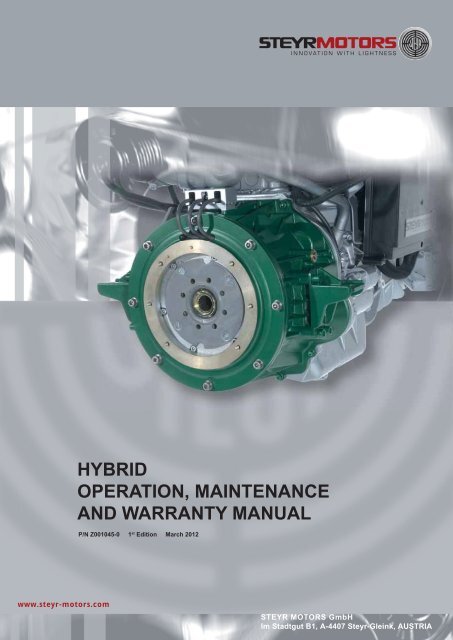
HYBRIDOPERATION, MAINTENANCEAND WARRANTY MANUALP/N Z001045-0 1 st Edition March 2012www.steyr-motors.comSTEYR MOTORS GmbHIm Stadtgut B1, A-4407 <strong>Steyr</strong>-Gleink, AUSTRIA
- 2 -Z001045-0_1_March 2012
WELCOME ABOARDCongratulations on your decision of choosing a STEYR MOTORS Hybrid system for your boat, <strong>and</strong> we hopeyou will enjoy it.STEYR MOTORS GmbH has developed a Hybrid system specifi cally for the marine environment. STEYRMOTORS Hybrid systems are designed to be adapted to various propulsion systems.To come up to your expectations, please study this <strong>manual</strong> thoroughly for your new STEYR MOTORSHybrid system to get suffi cient information on its <strong>operation</strong> <strong>and</strong> h<strong>and</strong>ling <strong>and</strong> to permit an optimal use of thevarious built-in functions.With kind regards,STEYR MOTORS GmbHYOUR STEYR MOTORSMARINE DEALER1st Edition, March 2012 P/N Z001045-0Z001045-0_1_March 2012 - 3 -
THIS PAGE IS INTENTIONALLY BLANK- 4 -Z001045-0_1_March 2012
TABLE OF CONTENTS1. GENERAL PART .......................................................................................................................................................... 61.1. General .......................................................................................................................................................... 61.2. Product References, Illustrations <strong>and</strong> Specifications .............................................................................. 71.3. Insurance .......................................................................................................................................................71.4. Stolen Unit .....................................................................................................................................................71.5. Owner Identification Card ...........................................................................................................................71.6. Commissioning Report ................................................................................................................................ 81.7. Dealer Service - Maintenance ...................................................................................................................... 81.8. Illustration Symbols ..................................................................................................................................... 81.9. Repair Service ..............................................................................................................................................91.10. Replacement Parts .......................................................................................................................................91.11. Before Casting Off .......................................................................................................................................91.12. Engine Submersion ..................................................................................................................................... 91.13. Boating Responsibilities ...........................................................................................................................101.14. Safety ...........................................................................................................................................................101.15. Symbols .......................................................................................................................................................112. FUNCTION OF HYBRID SYSTEM .............................................................................................................................. 132.1. General ........................................................................................................................................................ 132.2. Before Starting a Hybrid Engine ............................................................................................................... 142.3. Starting/Stopping a Hybrid Engine in Diesel-MODE (D-Mode) .............................................................15*) Starting/Stopping the Hybrid- Engine in Diesel-MODE (D-Mode) (for SOLAS only)2.4. Starting/Stopping a Hybrid Engine in Electrical-MODE (E-Mode)........................................................22*) Starting/Stopping the Hybrid- Engine in Electrical-MODE (E-Mode) (for SOLAS only)2.5. Start up with starter motor of Diesel Engine (Optional) ........................................................................362.6. Manual- Drive <strong>operation</strong> of Electrical-MODE (E-Mode) (Optional) ........................................................ 392.7. Hybrid- Engine Break-In procedure ........................................................................................................... 422.8. Operation after Break-In ............................................................................................................................ 442.9. Shifting in Electrical-MODE / E-Mode ........................................................................................................ 442.10. Gearbox - Information ................................................................................................................................. 452.11. How to Control Speed in Electrical-Mode / E-Mode .................................................................................452.12. Instrument indication during normal <strong>operation</strong> of Hybrid engines ........................................................ 462.13. Hybrid Electrical Equipment ...................................................................................................................... 50Instrument PanelHybrid PanelHybrid Control Unit (HCU)Hybrid Relay Box - Fuse (F12-10Amps)Coupling Actuator - Fuse (F11-7Amps)Hybrid BatteryMain Switch to Hybrid Battery (min. 400Amps)Fuse to Hybrid Battery (min. 300Amps)Auxiliary Electric (connected to Hybrid Battery)2.14. Hybrid Cooling System (Functional Description) .................................................................................... 562.15. Electronic Engine Control Unit (ECU) ...................................................................................................... 582.16. Warning lights <strong>and</strong> audible alarm ............................................................................................................. 582.17. Diagnostic System ..................................................................................................................................... 592.18. Emergency cut off switch (Lanyard) ........................................................................................................ 602.19. Economy in E-Mode <strong>operation</strong> ................................................................................................................. 612.20. Operating Procedure for Freezing Temperatures ................................................................................... 612.21. Salt Water Operation .................................................................................................................................. 612.22. Dry Operation ............................................................................................................................................. 613. TECHNICAL DATA ..................................................................................................................................................... 623.1. Model <strong>and</strong> Serial Number .......................................................................................................................... 623.2. Technical Data ............................................................................................................................................ 624. MAINTENANCE & TROUBLESHOOTING .................................................................................................................. 644.1. Service <strong>and</strong> Maintenance on Hybrid Engines .......................................................................................... 644.2. Trouble Check Chart ................................................................................................................................... 654.3. Reading Service Codes / Alarms from SCC ............................................................................................. 694.4. Principal Service Code List ........................................................................................................................ 704.5. Circuit Diagram Hybrid Relaybox .............................................................................................................. 725. DEALERS RESPONSIBILITIES ................................................................................................................................. 735.1. STEYR MOTORS - Dealer Check List ....................................................................................................... 735.2. Preparation for Off Season Storage ......................................................................................................... 745.3. Start-up after Storage ................................................................................................................................ 756. WARRANTY ................................................................................................................................................................ 776.1. Limited Engine Warranty ............................................................................................................................ 776.2. Service Network ......................................................................................................................................... 78Z001045-0_1_March 2012 - 5 -
1.1. GeneralThis MANUAL is published by STEYR MOTORS GmbH with the main intention to provide information in formof technical data <strong>and</strong> know-how based on our experience in the marine diesel engine business, which will enableyou, after thorough study to operate <strong>and</strong> check the engines on your boat, ensuring their operating safety,reliability <strong>and</strong> long service life.CE conformity:Under regular <strong>maintenance</strong>, as described in the chapter “Maintenance <strong>and</strong> Trouble Shooting”, the exhaustgas emission levels adhere to the limits stipulated, for pleasure boat <strong>operation</strong>, throughout the life time of theengine.All <strong>warranty</strong> claims to be addressed to your local STEYR MOTORS Marine Dealer.(We have to rely on your assistance however) For continuous improvement with regard to form <strong>and</strong> contentsof the information required.Your comments on the following questions would be much appreciated– Which descriptions or terms are not underst<strong>and</strong>able?– Which enlargements or complements do you suggest?– Where did content-related mistakes slip in?Please address your comments <strong>and</strong> ideas to your STEYR MOTORS – Marine Dealer.- 6 -Z001045-0_1_March 2012
1.2. Product References, Illustrations <strong>and</strong> SpecificationsWhen reference is made in this <strong>manual</strong> to a br<strong>and</strong> name, number, product or specifi c tool, an equivalentproduct may be used in place of the product referred to unless specifi cally stated otherwise. Equivalentproducts which are used must meet all current local regulations <strong>and</strong> st<strong>and</strong>ards to avoid hazards.Some countries may apply additional internal regulation. Please follow their advice appropriately, example:Austria:Sweden:Finl<strong>and</strong>:Norway:USA:USA:USA:Engl<strong>and</strong>:France:Germany:Italy:Bundesamt für SchiffahrtNavigation Offi ceNavigation Offi ceDNV = Det Norske VeritasUSCG = United States Coast GuardABYC = American Boat Yacht CouncilNMMA = National Marine Manufacturers AssociationLR = Lloyds Register of ShippingBV = Bureau VeritasGL = GERMANISCHER LloydRINA = Registro Italiano NavaleAll information, illustrations <strong>and</strong> specifi cations contained in this <strong>manual</strong> are based on the latest productinformation available at the time of printing. STEYR MOTORS GmbH reserves the right to make changesat any time, without notice, to specifications <strong>and</strong> models <strong>and</strong> also to discontinue models, as well asthe right to change specifications or parts at any time without incurring any obligation to equip sameon models manufactured prior to date of such change.Continual accuracy of this <strong>manual</strong> cannot be guaranteed.All illustrations used in this <strong>manual</strong> may not depict actual models or equipment <strong>and</strong> are intended asrepresentative views for reference only.1.3. InsuranceInsurance on your STEYR MOTORS Hybrid system <strong>and</strong> boat should be obtained as soon as practical forprotection against loss by fi re, theft, etc. Consult your local insurance agent.1.4. Stolen UnitThe model <strong>and</strong> serial numbers on your engine are important for you. As to the location of these importantnumbers, refer to Model <strong>and</strong> Serial Numbers in the section Technical Data.Record each of these numbers in the spaces provided at the end of OM&W Manual (P/N Z001022/0)supplied with your STEYR MOTORS Marine Engine <strong>and</strong> on a separate sheet.In case of theft, report the model <strong>and</strong> serial numbers to your local authorities <strong>and</strong> your insurance agent.1.5. Owner Identification CardWhen you purchases your boat, your dealer was obliged to issue an owner identifi cation card for yourSTEYR MOTORS Marine Engine.This owner identifi cation card gives proof <strong>and</strong> is to be submitted in case of <strong>warranty</strong> claims.Z001045-0_1_March 2012 - 7 -
1.6. Commissioning ReportYour STEYR MOTORS Marine dealer is also obliged to complete the commissioning report ( to find inOperation, Maintenance <strong>and</strong> Warranty Manual Z001140/0 chapter "DEALER´S RESPONSIBILITIES").Required tests <strong>and</strong> measurements are to be carried out accordingly.A copy of the commissioning report <strong>and</strong> engine registration card are to be forwarded to STEYR MOTORSGmbH.1.7. Dealer Service - MaintenanceNOTE: Please do not forget to have confi rmed in your <strong>manual</strong> that the installation <strong>and</strong> <strong>maintenance</strong> havebeen carried out in accordance with the guidelines.This is also an opportunity to clarify with your STEYR MOTORS marine dealer possible questions arisenduring the fi rst running hours on your boat, <strong>and</strong> to establish a service <strong>and</strong> <strong>maintenance</strong> routine.Services will be performed by STEYR MOTORS Marine Dealers at local rates.Costs for service material to be paid by the owner.1.8. Illustration Symbols- 8 -Z001045-0_1_March 2012
1.15. SymbolsCertain symbols or combinations of symbols may appear on your STEYR MOTORS Marine Engine Hybrid Systemor on its accessories. It is very important that you underst<strong>and</strong> their meaning or purpose. If any symbol is not clearlyunderstood, see your AUTHORIZED STEYR MOTORS DEALER.Hazard warning sign:electricity, danger of deathH<strong>and</strong>ling only allowed from certifi cated personal(person must have certifi cate to work on electricalsystems with <strong>operation</strong>al voltages above 48V DC)“Safety Warning” SymbolsMeans risk of SERIOUS injury is present.Follow instructions in the Operation,Maintenance & Warranty Manual beforeusing motor or accsessory.Means place shift control in NEUTRALbefore starting motor. Follow instructions inOperation, Maintenance & Warranty Manualbefore starting motor.Indicates that ELECTRICITY of more than50 volts is present.Indicates that contents are underpressure.Identifies poisonous material.Indicates a potential fire hazard.“Position Indicator” SymbolsIndicates upward movement.Example: While boat is at planing speed,activating trim switch to raise the bow ofthe boat.Indicates downward movement.Example: While boat is at planingspeed, activating trim switch to lowerthe bow of the boat.“Condition” SymbolsIndicates gear shift control positions:FORWARD, NEUTRAL <strong>and</strong> REVERSEIndentifies the meter which indicatesaccumulative running hours of engine.Identifies the meter which indicatesbattery voltage or amperage.Identifies the meter which indicatesengine speed expressed in revolutionsper minute.Identifies battery or a meter wichindicates status of battery-generatorcharging system.orIndicates the amount of liquid in tank.Indentifies the meter which indicatesengine coolant pressure.Identifies the meter which indicatesengine coolant temperature.FILTER: Identifies a device whichremoves contaminants from engine’soil system.Identifies the meter which indicates thepressure of engine’s lubricating system.“Functional Description” SymbolsFILTER: Identifies a device whichremoves contaminants from fuel.Identifies the EMERGENCY IGNITIONCUT-OFF SWITCH.Emergency engine stop.FUSE: Identifies a device which protectsthe electrical system from overload.Identifies the negative ground ornegative voltage connection.Identifies engine drain plugs <strong>and</strong> fittings.Identifies the operating device for startingthe motor.Identifies the STOP SWITCH.It may also identify STOP position ofthe throttle control.“Instructional” SymbolsIndicates FUEL is to be used orFUEL is present.Means read your Operation,Maintenance & Warranty Manualbefore operating the product. It containsinformation or instructions vital for<strong>operation</strong> of product.Indicates areas to be lubricated.Indicates OIL is to be used orOIL is present.ENGINE OIL FILL: Location forintroduction of oil into the engine.Indicates lubricating oil used intransmissions.Z001045-0_1_March 2012 - 11 -
THIS PAGE IS INTENTIONALLY BLANK- 12 -Z001045-0_1_March 2012
CLEAN EFFICIENT POWERCLEAN EFFICIENT POWER2. FUNCTION OF HYBRID SYSTEM2.1. GeneralStarting procedure for the STEYR MOTORS Marine Hybrid Engine is the same for both cold <strong>and</strong> warm engines.The Engine Control Unit (=ECU) automatically regulates the fuel supply <strong>and</strong> the preheating period for anygiven temperature.Therefore the throttle lever should remain in neutral position.Hybrid Engines offer basically two different <strong>operation</strong> modes:• D-MODE for conventional <strong>operation</strong> of the combustion engineNOTE:If D-Mode is activated, SCC (=STEYR Control Center) displays system condition in menu “HCU” as followingillustrated:STEYR-CONTROL-CENTERR49.16.45N 48.08.56N 102.41.11W 014.27.47W 57,4 117 14:05 22:57GENER.SPEED/KN10.0 3410,51,5 rpm022 310rpm x 1000A455 3 4 43 85 4 85E-Mode ready26 °C bar 525D-Mode ready °C °C20 1090 86 HCU ok15050 120 6HCUOIL/BAR250250RPM2650 150050V01009870 131548,00E-Speed HCU/CURBATTERYHybrid statustus2,8 6.377.8 E-MOTOR 73TEMP/°C120MAINSWITCHGENER.Hybrid statusE-Mode readyD-Mode readyHCU ok11-013• E-MODE for electric <strong>operation</strong>NOTE:If E-Mode is activated, SCC (=STEYR Control Center) displays system condition in menu “HCU”as followingillustrated:STEYR-CONTROL-CENTER49.16.45N 48.08.56N 102.41.11W 014.27.47W 57,4 117 14:05 22:57GENER.SPEED/KN10.0 3410,51,5 rpm022 310rpm x 1000A455 3 4 43 85 4 85E-Mode ready26 °C bar 525D-Mode ready °C °C20 1090 86 HCU ok15050 120 6HCUOIL/BAR250250RPM2650 150050V01009870 131548,00E-Speed HCU/CURBATTERYHybrid statustus2,8 6.377.8 E-MOTOR 73TEMP/°C120MAINSWITCHHybrid statusE-Mode readyD-Mode readyHCU ok11-016Z001045-0_1_March 2012 - 13 -
2.2 Before Starting a Hybrid EngineFamiliarize yourself with the h<strong>and</strong>ling of the boat, in particular how to use transmission, <strong>and</strong> then proceed asfollows:1. Check the bilge for excessive water accumulation. Always keep the bilge clean <strong>and</strong> dry.Never allow the water level in the engine compartment to exceed the bottom of the oil pan. If water accumulationis unavoidable, install a bilge pump with an automatic control switch.For Hybrid systems ensure optically that all Hybrid Electrical Components (e.g. Generator, Hybrid Control Unit(HCU), U,V,W-cables etc.) are not affected by water.NOTE: The water level in the boat's engine compartment will increase when the boat is operated at a highincline before planing speed is reached. Excessive water accumulation in the engine compartment/ bilge maycause engine failures.2. Open the raw water intake valve for Diesel engine <strong>and</strong> Hybrid Cooling SystemNOTE: Operate the engine <strong>and</strong> Hybrid system only while the raw water supply is assured or the cooling systemis equipped with a fl ushing device. The engine- raw water pump <strong>and</strong>/or Hybrid electrical cooling pumps will bedamaged <strong>and</strong>/or will overheat if operated without cooling water.3. Open the fuel stop valve.NOTE: Only start the engine when a bubble-free fuel supply is guaranteed. Prior to fi rst start-up of theengine (after installation, after storage etc.), purge the fuel system by "ignition ON" for 6 x 10 sec.4. Check the operating levels of:* coolant* oil* hydraulic oil* transmission oil* Fuel5. Control electric system of EngineCheck charge state of engine’s starter battery.NOTE: Charge starter battery according battery manufacturers instructions. See therefor for Operation Manualof starter battery. Starter battery is not in scope of delivery from STEYR MOTORS!6. Check Hybrid system* Notice optically if protection covers are mounted on following components:11-011- HCU: cover U, V, W-protection cap B+, B-- Generator: cover U, V, W- Hybrid-Battery: Protection cap B+, B-11-00811-004NOTE: All parts supplied from STEYR MOTORS covered with protection- covers <strong>and</strong> accordingly signedcan be only opened, maintained <strong>and</strong> repaired from authorized technicans.* Check charge state of Hybrid BatteryNOTE: Hybrid Battery not in st<strong>and</strong>ard scope of delivery from STEYR MOTORSNOTE: If charging of Hybrid battery is necessary, proceed according Hybrid Battery manufacturers instructions.NOTE: If Hybrid battery charge state is above >57V, engine must be started with conventional startermotor(to start engine with conventional startermotor follow instructions as described in chapter 2.5- 14 -Z001045-0_1_March 2012
2.3 Starting/Stopping a Hybrid Engine in Diesel- MODE (D-Mode)STARTING HYBRID- ENGINE IN D-MODEATTENTION:Starting a Hybrid Engine by igniton key will start the combustion engine with Hybrid-Generator (=Engineis not started with conventional starter motor)!To start the Hybrid Engine with conventional starter motor refer to chapter 2.5 (STEYR MOTORS recommendsto use conventional starter- motor only in emergency- cases. If conventional starter- motor is used, contactauthorized STEYR MOTORS DEALER for fault investigation as soon as possible)Before continuing with procedure, check system status is as following:• Switch Panel > position “OFF”OFFONSTART11-030• Hybrid Panel > postion “OFF”E-ModeManualDrive12 VStartE-ModeManualDrive12 VStartCLEAN EFFICIENT POWER• Throttle Lever > position “D”11-028DJHKMICEGF11-007Z001045-0_1_March 2012 - 15 -
0200,51551,52902500CLEAN EFFICIENT POWER25005050851001201. To start the Hybrid- engine in D-MODE, move throttle lever into idle position <strong>and</strong> gear into neutral position.2. Turn ignition key into position ignition "ON".An audible alarm will sound (0,7sec.) <strong>and</strong> the warning lights are illumiated (temporary), indicating the correctfunction of the audible <strong>and</strong> visual warning systems0,7 secOFFON0,7 secSTART0,7 sec11-031NOTE: In case of a low temperature start, wait until the combined oil pressure/glow plug pre-heating indicationlight is turned off, then continue with the start procedure.3. Wait till SCC has completely started up showing below screen- menu “Main”STEYR-CONTROL-CENTER49.16.45N 48.08.56N 102.41.11W 014.27.47W 57,4 117 14:05 22:57HCUHCUSPEED/KN10.0 3412 3rpm x 10004RPM2650 1500MAIN05SWITCH3 4 43 85 426 bar 52 °C 51068 150120 62,8 6.377.8 73OIL/BARTEMP/°C11-0344.Select on SCC menu „HCU” to enter below shown screen.STEYR-CONTROL-CENTER49.16.45N 48.08.56N 014.27.47W 102.41.11W 57,4 117 14:05 22:57SPEED/KN10.0 34012 3rpm x 10003 443 85426 bar 52°C51086 15012062,8 6.377.8 73OIL/BARTEMP/°C45RPM2650 1500HCUMAINSWITCHSTEYR-CONTROL-CENTERR49.16.45N 48.08.56N 102.41.11W 014.27.47W 57,4 117 14:05 22:57GENER.SPEED/KN10.0 34rpm12 3rpm x 1000A9870 131E-Speed HCU/CURHybrid statustus45RPM2650 15003 4 43 85 4E-Mode ready26 °C bar 525D-Mode ready °C °C1068 HCU ok150120 6HCU2,8 6.377.8 E-MOTOR 73OIL/BARTEMP/°CV48,00BATTERYMAINSWITCHGENER.Hybrid statusE-Mode readyD-Mode readyHCU ok11-03211-013- 16 -Z001045-0_1_March 2012
Check following parameters on screen „HCU” before continuing with start- procedure:- E-Mode ready= red illustrated,- D-Mode ready= green illustrated,- HCU o.k.=green illustrated- GENER.= green illustrated,- BATTERY= between min.45V/max.57V .NOTE: If parameters are not displayed as described above, follow chapter 4.TROUBLE SHOOTING or contactyour authorized STEYR MOTORS marine DEALER.5. Turn ignition key into position "START„ <strong>and</strong> hold in this position until "starting" of engine, but under nocircumstances hold in this position for more than ten seconds.If engine does not start, release ignition key momentarily <strong>and</strong> repeat starting procedure.OFFONSTART11-039ATTENTION: If starting of Hybrid Engine in D-Mode is not possible, in emergency cases conventionalstarter-motor can be used for start- up.To start the Hybrid- engine with conventional startermotor refer to chapter 2.5 (STEYR MOTORS recommendsto use conventional starter- motor only in emergency- cases. If conventional starter-motor is used, contactauthorized STEYR MOTORS DEALER for fault investigation as soon as possible)6. As soon as engine starts, release ignition key. The audible alarm will stop when normal oil pressure hasbeen reached.ATTENTION: If engine fails to start within one minute <strong>and</strong>/or repeated attempts, try to start in emergency caseswith conventional startermotor (proceed according chapter 2.5) or contact your STEYR MOTORS Marine dealer.Never turn ignition key to position "START" when engine is running.Z001045-0_1_March 2012 - 17 -
STOPPING HYBRID ENGINE in D-MODE1. Move throttle lever into idle position <strong>and</strong> gear in neutral position.2. Cool down the engine.3. Turn ignition key to “OFF” position.ATTENTION: Do not stop engine at speeds above idle or accelerate engine while turning ignition “OFF”.This may result in engine failures.OFFONSTART11-039- 18 -Z001045-0_1_March 2012
*) Starting/Stopping the Hybrid- Engine in Diesel- MODE (D-Mode) (for SOLAS only)STARTING HYBRID- ENGINE IN D-MODE (for SOLAS only)ATTENTION:Starting a Hybrid-engine by push button will start the Hybrid Engine with Hybrid-Generator (=Engine isnot started with conventional starter motor)!To start the Hybrid Engine with conventional starter motor refer to chapter 2.5 (STEYR MOTORS recommendsto use conventional starter- motor only in emergency- cases. If conventional starter- motor is used, contactauthorized STEYR MOTORS DEALER for fault investigation as soon as possible)Before continuing with procedure, check system status is as following:• Push Button Panel > postion “OFF”STARTONOFF11-041• Hybrid Panel > postion “OFF”E-ModeManualDrive12 VStartE-ModeManualDrive12 VStartCLEAN EFFICIENT POWER• Throttle Lever > position “D”11-028DJHKMICEGF11-007Z001045-0_1_March 2012 - 19 -
3 442651023 854512060200,511,5255 3 4 426510902500CLEAN EFFICIENT POWER25020501003 85 4 85550 120 6 1201. To start the Hybrid- engine in D-MODE, move throttle lever into idle position <strong>and</strong> gear into neutral position.2. Press the push button for ignition (ill.F;red) (push button lock in place);An audible alarm will sound (for 0,7sec.) <strong>and</strong> the warning lights are illuminated (temporary), indicating the correctfunction of the audible <strong>and</strong> visual warning system.STARTONOFF11-041NOTE:In case of a low temperature start, wait until the combined oil pressure/glow plug preheating indication light isturned off, then continue with the start procedure.3.Wait till SCC has completely started up showing below screen- menu “Main”STEYR-CONTROL-CENTER49.16.45N 48.08.56N 102.41.11W 014.27.47W 57,4 117 14:05 22:57HCUHCUSPEED/KN10.0 3412 3rpm x 10004RPM2650 1500MAIN05SWITCH2103 4 43 85 46bar 52 °C 568 1502,8 6.377.8 73OIL/BARTEMP/°C120 611-0344.Select on SCC menu “HCU” to enter below shown screen.STEYR-CONTROL-CENTER49.16.45N 48.08.56N 014.27.47W 102.41.11W 57,4 117 14:0522:57SPEED/KN10.0 34012 3rpm x 100045bar °C86 1502,8 6.377.8 73OIL/BARTEMP/°CRPM2650 1500HCUMAINSWITCHSTEYR-CONTROL-CENTERR49.16.45N 48.08.56N 102.41.11W 014.27.47W 57,4 117 14:05 22:57GENER.SPEED/KN10.0 34rpm12 3rpm x 1000A9870 131E-Speed HCU/CURHybrid statustus45RPM MAIN2650 1500E-Mode ready°C bar D-Mode ready °C °C68 HCU ok150HCU2,8 6.377.8 E-MOTOR 73OIL/BARTEMP/°CV48,00BATTERYSWITCHGENER.Hybrid statusE-Mode readyD-Mode readyHCU ok11-03211-013- 20 -Z001045-0_1_March 2012
Check following parameters on screen „HCU” before continuing with start- procedure:- E-Mode ready= red illustrated,- D-Mode ready= green illustrated,- HCU o.k.=green illustrated- GENER.= green illustrated,- BATTERY= between min.45V/max.57V .NOTE: If parameters are not displayed as described above, follow chapter chapter 4.TROUBLE SHOOTINGor contact your authorized STEYR MOTORS marine DEALER.5. Press the button START (ill.G; green) <strong>and</strong> hold in this position until "starting" of engine, but under nocircumstances hold in this position for more than ten seconds.If engine does not start, release start – push button momentarily <strong>and</strong> repeat starting procedure.ATTENTION: If Hybrid- engine is not to start, in emergency cases conventional startermotor can beused for start- up. To start the Hybrid- engine with conventional startermotor refer to chapter 2.5(STEYR MOTORS recommends to use conventional starter- motor only in emergency- cases. If conventionalstarter-motor is used, contact authorized STEYR MOTORS DEALER for fault investigation as soon as possible)6. As soon as engine starts, release start button. The audible alarm will stop when normal oil pressure hasbeen reached.ATTENTION: If engine fails to start within one minute <strong>and</strong>/or repeated attempts, try to start in emergency caseswith conventional startermotor (proceed according chapter 2.5) or contact your STEYR MOTORS Marine dealer.Never push start button when engine is running.STOPPING HYBRID ENGINE in D-MODE (for SOLAS only)1. Move throttle lever into idle position <strong>and</strong> gear in neutral position.2. Cool down the engine.3. Press push button ignition ON/OFF (ill.F) to disengage from locking position <strong>and</strong> to shut OFF the engine.ATTENTION:Do not stop engine at speeds above idle or accelerate engine while turning off ignition. This may result inengine failures.Z001045-0_1_March 2012 - 21 -
2.4 Starting/Stopping the Hybrid- Engine in Electrical- MODE (E-Mode)STARTING HYBRID- ENGINE IN E-MODEBefore continuing with procedure, check system status is as following:• Switch Panel > position “OFF”OFFONSTART11-030• Hybrid Panel > position “OFF”E-ModeManualDrive12 VStartE-ModeManualDrive12 VStartCLEAN EFFICIENT POWER• Throttle Lever > position “D”11 028DJHKMICEGF11-007- 22 -Z001045-0_1_March 2012
3 442651023 854512060200,51551,52902500CLEAN EFFICIENT POWER25005050851001201.To start the Hybrid- engine in E-MODE, move throttle lever into idle position <strong>and</strong> gear into neutral position.2.Turn ignition key into position ignition "ON".An audible alarm will sound (0,7sec.) <strong>and</strong> the warning lights are illuminated (temporary), indicating the correctfunction of the audible <strong>and</strong> visual warning systems.0,7 secOFFON0,7 secSTART0,7 sec11-031NOTE:In case of a low temperature start, wait until the combined oil pressure/glow plug pre-heating indication light isturned off, then continue with the start procedure.3.Wait till SCC has completely started up showing below screen- menu “Main”STEYR-CONTROL-CENTER49.16.45N 48.08.56N 102.41.11W 014.27.47W 57,4 117 14:05 22:57HCUHCUSPEED/KN10.0 3412 3rpm x 10004RPM2650 1500MAIN05SWITCH2103 4 43 85 46bar 52 °C 568 1502,8 6.377.8 73OIL/BARTEMP/°C120 611-0344.Select on SCC menu “HCU” to enter below shown screen.STEYR-CONTROL-CENTER49.16.45N 48.08.56N 014.27.47W 102.41.11W 57,4 117 14:0522:57SPEED/KN10.0 34012 3rpm x 100045bar °C86 1502,8 6.377.8 73OIL/BARTEMP/°CRPM2650 1500HCUMAINSWITCHSTEYR-CONTROL-CENTERR49.16.45N 48.08.56N 102.41.11W 014.27.47W 57,4 117 14:05 22:57GENER.SPEED/KN10.0 34rpm12 3rpm x 1000A9870 131E-Speed HCU/CURHybrid statustus45RPM2650 15003 4 43 85 4E-Mode ready26 °C bar 525D-Mode ready °C °C1068 HCU ok150120 6HCU2,8 6.377.8 E-MOTOR 73OIL/BARTEMP/°CV48,00BATTERYMAINSWITCHGENER.Hybrid statusE-Mode readyD-Mode readyHCU ok11-01311-032Z001045-0_1_March 2012 - 23 -
CLEAN EFFICIENT POWERCheck following parameters on screen „HCU” before continuing with start- procedure:- E-Mode ready = red illustrated,- D-Mode ready = green illustrated,- HCU o.k.= green illustrated- GENER.= green illustrated,- BATTERY = between min.45V/max.57V .NOTE:If parameters are not displayed as described above, follow chapter 4.TROUBLE SHOOTING or contact yourauthorized STEYR MOTORS marine DEALER.5. Push button „E-Mode“ on Hybrid panel as below shown to disengage Diesel engine from Hybrid Generator.E-ModeManualDrive12 VStartE-ModeManualDrive12 VStartE-ModeManualDrive12 VStartE-ModeManualDrive12 VStartCLEAN EFFICIENT POWER11-026CLEAN EFFICIENT POWERIf disengagement-process was successful, below illustrated screen appears on SCC under menu „HCU”Check following parameters on screen „HCU” before continuing with start- procedure:- E-Mode ready = green illustrated- D-Mode ready = red illustrated- HCU o.k.= green illustrated- GENER. = green illustrated,- BATTERY = between min.45V/max.57V11-019STEYR-CONTROL-CENTER49.16.45N 48.08.56N 102.41.11W 014.27.47W 57,4 117 14:05 22:57GENER.SPEED/KN10.0 340,51rpm1,52 310rpm x 1000A455 3 4 43 85 4 85E-Mode ready26 °C bar 525D-Mode ready °C °C20 1090 86 HCU ok15050 120 6HCUOIL/BARRPM2650 15002502500100209870 131548,00E-Speed HCU/CURBATTERYHybrid statustus2,8 6.377.8 E-MOTOR 7350VTEMP/°C120MAINSWITCHHybrid statusE-Mode readyD-Mode readyHCU ok11-016NOTE: When button „E-Mode“ is activated on Hybrid panel it can be noticed audible that Hybrid couplingactuator is disengaging/engaging between Diesel engine <strong>and</strong> Hybrid Generator- 24 -Z001045-0_1_March 2012
CLEAN EFFICIENT POWER6. To start E-MODE <strong>operation</strong>, move throttle- lever in forward position.On SCC, menu “HCU”, fi eld “GENERATOR” will change to “E-DRIVE” as soon Hybrid- Generator isturning (see below illustration)STEYR-CONTROL-CENTERR49.16.45N 48.08.56N 102.41.11W 014.27.47W 57,4 117 14:05 22:57GENER.SPEED/KN10.0 340,51rpm1,52 310rpm x 1000A455 3 4 43 85 4 85E-Mode ready26 °C bar 525D-Mode ready °C °C20 1090 68 HCU ok15050 120 6HCUOIL/BARRPM2650 15002502500100209870 131548,00E-Speed HCU/CURBATTERYHybrid statustus2,8 6.377.8 E-MOTOR 7350VTEMP/°C120MAINSWITCHE-DRIVEHybrid statusE-Mode readyD-Mode readyHCU ok11-015NOTE: During E-MODE <strong>operation</strong> (forward- <strong>and</strong> neutral- position) <strong>and</strong> ignition „ON“ warning-light batterychargewill illuminate.Warning- light battery-charge will extinguish as soon as D-MODE <strong>operation</strong> is started (=Diesel engine rotatesalternator; alternator charges engine’s starter battery)OFFONSTARTHybrid statusE-Mode readyD-Mode readyHCU ok11-003Z001045-0_1_March 2012 - 25 -
CLEAN EFFICIENT POWERSTOPPING HYBRID ENGINE in E-MODEBefore continuing with procedure, check system status is as following:• SCC:STEYR-CONTROL-CENTER49.16.45N 48.08.56N 102.41.11W 014.27.47W 57,4 117 14:05 22:57GENER.SPEED/KN10.0 342 310rpm x 10000,51,5 rpm1 A4022502509870 1315E-Speed HCU/CURRPM2650 150050V010048,00BATTERYHybrid statustus55 3 4 43 85 4 85E-Mode ready26 °C bar 525D-Mode ready °C °C20 1090 86 HCU ok15050 120 6 120HCU2,8 6.377.8 E-MOTOR 73OIL/BARTEMP/°CMAINSWITCHHybrid statusE-Mode readyD-Mode readyHCU ok11-016• On Instrument PanelOFFONSTARTHybrid statusE-Mode readyD-Mode readyHCU ok11-003• throttle- lever in forward or neutralDJHKMICEGF11-007- 26 -Z001045-0_1_March 2012
CLEAN EFFICIENT POWER1. Move throttle lever into idle position <strong>and</strong> gear in neutral position.2. To stop E-Mode <strong>operation</strong> following two variants exists:VARIANT A:1. Push button „E-Mode“ on Hybrid panel to engage Diesel engine <strong>and</strong> Hybrid Generator (see below illustration)E-ModeManualDrive12 VStartE-ModeManualDrive12 VStartE-ModeManualDrive12 VStartE-ModeManualDrive12 VStartCLEAN EFFICIENT POWER11-022CLEAN EFFICIENT POWERNOTE:If button “E-Mode” on Hybrid panel is pushed during Hybrid-Generator is turning, the electrical propulsion isautomatically stopped <strong>and</strong> Diesel Engine will be engaged with Hybrid Generator.To start Hybrid Engine in D-Mode, bring throttle- lever in neutral position <strong>and</strong> continue with starting- process ofD-Mode as described (see chapter 2.3)11 0252. SCC displays under menu „HCU” following screen:STEYR-CONTROL-CENTERR49.16.45N 48.08.56N 102.41.11W 014.27.47W 57,4 117 14:05 22:57GENER.SPEED/KN10.0 3410,51,5 rpm0212 3rpm x 1000A2502509870 131E-Speed HCU/CUR045RPM2650 150050V010048,00BATTERYHybrid statustus55 3 4 43 85 4 85E-Mode ready26 °C bar 525D-Mode ready °C °C20 1090 68 HCU ok15050 120 6 120HCU2,8 6.377.8 E-MOTOR 73OIL/BARTEMP/°CMAINSWITCHGENER.Hybrid statusE-Mode readyD-Mode readyHCU ok11-013NOTE: D- Mode ready = green illustrated3.Turn ignition key to “OFF” position to switch the system OFFor Start Hybrid engine in D-Mode (see chapter 2.3)Z001045-0_1_March 2012 - 27 -
CLEAN EFFICIENT POWERVARIANT B:1. Turn ignition key to OFF position.NOTE:Hybrid- engines automatically switch to D-MODE if ignition is turned “OFF”.When Ignition is „OFF“ , Hybrid system must be in D-MODE condition!Evaluate System is in “D-Mode” condition from SCC- menu “HCU”STEYR-CONTROL-CENTERR49.16.45N 48.08.56N 102.41.11W 014.27.47W 57,4 117 14:05 22:57GENER.SPEED/KN10.0 3410,51,5 rpm022 310rpm x 1000A455 3 4 43 85 4 85E-Mode ready26 °C bar 525D-Mode ready °C °C20 1090 68 HCU ok15050 120 6HCUOIL/BAR250250RPM2650 150050V01009870 131548,00E-Speed HCU/CURBATTERYHybrid statustus2,8 6.377.8 E-MOTOR 73TEMP/°C120MAINSWITCHGENER.Hybrid statusE-Mode readyD-Mode readyHCU ok11-013NOTE: D- Mode ready = green illustrated- 28 -Z001045-0_1_March 2012
*) Starting/Stopping the Hybrid- Engine in Electrical-MODE (E-Mode) (for SOLAS only)STARTING HYBRID- ENGINE IN E-MODE (for SOLAS only)Before continuing with procedure, check system status is as following:• Push Button Panel > postion “OFF”STARTONOFF11-041• Hybrid Panel > postion “OFF”E-ModeManualDrive12 VStartE-ModeManualDrive12 VStartCLEAN EFFICIENT POWER• Throttle Lever > position “D”11 028DJHKMICEGF11-007Z001045-0_1_March 2012 - 29 -
3 4 42651023 85 45120 60200,51551,52902500CLEAN EFFICIENT POWER25005050851001201.To start the Hybrid- engine in E-MODE, move throttle lever into idle position <strong>and</strong> gear into neutral position.2. Press the push button for ignition (ill.F;red) (push button lock in place); An audible alarm will sound(0,7sec.)<strong>and</strong> the warning lights are illuminated (temporary), indicating the correct function of the audible <strong>and</strong> visualwarning system.STARTONOFF11-041NOTE:In case of a low temperature start, wait until the combined oil pressure/glow plug pre-heating indication light isturned off, then continue with the start procedure.3.Wait till SCC has completely started up showing below screen- menu “Main”STEYR-CONTROL-CENTER49.16.45N 48.08.56N 102.41.11W 014.27.47W 57,4 117 14:05 22:57HCUHCUSPEED/KN10.0 3412 3rpm x 10004RPM2650 1500MAIN05SWITCH2103 4 43 85 46bar 52 °C 568 1502,8 6.377.8 73OIL/BARTEMP/°C120 611-0344.Select on SCC – menu “HCU”“ to enter below shown screen.STEYR-CONTROL-CENTER49.16.45N 48.08.56N 014.27.47W 102.41.11W 57,4 117 14:05 22:57HCUSTEYR-CONTROL-CENTERR49.16.45N 48.08.56N 102.41.11W 014.27.47W 57,4 117 14:05 22:57GENER.SPEED/KN10.0 34012 3rpm x 100045bar °C6 8 1502,8 6.377.8 73OIL/BARTEMP/°CRPM2650 1500MAINSWITCHGENER.SPEED/KN10.0 34rpm12 3rpm x 1000A9870 131E-Speed HCU/CURHybrid statustus45RPM2650 15003 4 43 85 4E-Mode ready26 °C bar 525D-Mode ready °C °C1086 HCU ok150120 6HCU2,8 6.377.8 E-MOTOR 73OIL/BARTEMP/°CV48,00BATTERYMAINSWITCHHybrid statusE-Mode readyD-Mode readyHCU ok11-03211-013- 30 -Z001045-0_1_March 2012
CLEAN EFFICIENT POWERCheck following parameters on screen „HCU” before continuing with start- procedure:- E-Mode ready = red illustrated,- D-Mode ready = green illustrated,- HCU o.k.= green illustrated- GENER. = green illustrated,- BATTERY = between min.45V/max.57V .NOTE:If parameters are not displayed as described above, follow chapter 4.TROUBLE SHOOTING or contact yourauthorized STEYR MOTORS marine DEALER.5.Push button „E-Mode“ on Hybrid panel as below shown to disengage Diesel engine from Hybrid Generator.E-ModeManualDrive12 VStartE-ModeManualDrive12 VStartE-ModeManualDrive12 VStartE-ModeManualDrive12 VStartCLEAN EFFICIENT POWER11-026CLEAN EFFICIENT POWER11-019STEYR-CONTROL-CENTER49.16.45N 48.08.56N 102.41.11W 014.27.47W 57,4 117 14:05 22:57GENER.SPEED/KNRPM10.0 342 3 2650 15001050rpm x 10000,51,5 rpm1 A40200Hybrid statustus55 3 4 43 85 4 85E-Mode ready26 °C bar 525D-Mode ready °C °C1090 86 HCU ok15050 120 6 1202,8 6.377.8 E-MOTOR 73OIL/BARTEMP/°CHCU2987E-Speed250250131HCU/CUR50V10048,00BATTERYMAINSWITCHHybrid statusE-Mode readyD-Mode readyHCU ok11-016If disengagement is successful, screen as above illustrated appears on SCC under menu „HCU”Check following parameters on screen „HCU” before continuing with start- procedure:- E-Mode ready = green illustrated- D-Mode ready = red illustrated- HCU o.k.= green illustrated- GENER. = green illustrated,- BATTERY = between min.45V/max.57VNOTE:When button „E-Mode“ is activated on Hybrid panel it can be audible noticed that Hybrid coupling actuator isdisengaging/engaging between Diesel engine <strong>and</strong> Hybrid GeneratorZ001045-0_1_March 2012 - 31 -
CLEAN EFFICIENT POWER6. To start E-MODE <strong>operation</strong>, move throttle- lever in forward positionOn SCC, menu “HCU”, fi eld “GENERATOR” will change to “E-DRIVE” as soon Hybrid- Generator is turning(see below illustration)STEYR-CONTROL-CENTERR49.16.45N 48.08.56N 102.41.11W 014.27.47W 57,4 117 14:05 22:57GENER.SPEED/KN10.0 3410,51,5 rpm022 310rpm x 1000A455 3 4 43 85 4 85E-Mode ready26 °C bar 525D-Mode ready °C °C20 1090 86 HCU ok15050 120 6HCUOIL/BAR250250RPM2650 150050V01009870 131548,00E-Speed HCU/CURBATTERYHybrid statustus2,8 6.377.8 E-MOTOR 73TEMP/°C120MAINSWITCHE-DRIVEHybrid statusE-Mode readyD-Mode readyHCU ok11-015NOTE: During E-MODE <strong>operation</strong> (forward- <strong>and</strong> neutral- position) <strong>and</strong> ignition „ON“ warning-light batterychargewill illuminate.Warning- light battery-charge will extinguish as soon as D-MODE <strong>operation</strong> is started (=Dieselengine rotates alternator; alternator charges engine’s starter battery)STARTONOFF11-036- 32 -Z001045-0_1_March 2012
CLEAN EFFICIENT POWERSTOPPING HYBRID- ENGINE IN E-MODE (for SOLAS only)Before continuing with procedure, check system status is as following:• SCC:STEYR-CONTROL-CENTER49.16.45N 48.08.56N 102.41.11W 014.27.47W 57,4 117 14:05 22:57GENER.SPEED/KN10.0 3410,51,5 rpm022 310rpm x 1000A455 3 4 43 85 4 85E-Mode ready26 °C bar 525D-Mode ready °C °C20 1090 86 HCU ok15050 120 6HCUOIL/BAR250250RPM2650 150050V01009870 131548,00E-Speed HCU/CURBATTERYHybrid statustus2,8 6.377.8 E-MOTOR 73TEMP/°C120MAINSWITCHHybrid statusE-Mode readyD-Mode readyHCU ok11-016• Instrument Panel:STARTONOFF11-036• Throttle- lever in forward or neutralDJHKMICEGF11-0071. Move throttle lever into idle position <strong>and</strong> gear in neutral position2. To stop E-Mode <strong>operation</strong> following two variants exists:Z001045-0_1_March 2012 - 33 -
CLEAN EFFICIENT POWERVARIANT A:1. Push button „E-Mode“ on Hybrid panel as below shown to engage Diesel engine <strong>and</strong> Hybrid Generator.E-ModeManualDrive12 VStartE-ModeManualDrive12 VStartE-ModeManualDrive12 VStartE-ModeManualDrive12 VStartCLEAN EFFICIENT POWER11-022CLEAN EFFICIENT POWER11-0252. SCC displays under menu „HCU” following screen:STEYR-CONTROL-CENTERR49.16.45N 48.08.56N 102.41.11W 014.27.47W 57,4 117 14:05 22:57GENER.SPEED/KN10.0 3410,51,5 rpm022 310rpm x 1000A455 3 4 43 85 4 85E-Mode ready26 °C bar 525D-Mode ready °C °C20 1090 68 HCU ok15050 120 6HCUOIL/BAR250250RPM2650 150050V01009870 131548,00E-Speed HCU/CURBATTERYHybrid statustus2,8 6.377.8 E-MOTOR 73TEMP/°C120MAINSWITCHGENER.Hybrid statusE-Mode readyD-Mode readyHCU ok11-013NOTE: D- Mode ready = green illustrated3. Press push button ignition ON/OFF (ill.F) to disengage from locking position <strong>and</strong> to shut OFF the systemor Start Hybrid engine in D-Mode (see chapter 2.3)STARTONOFF11-041ATTENTION: Do not stop engine at speeds above idle or accelerate engine while turning “OFF” ignition. Thismay result in engine failures.- 34 -Z001045-0_1_March 2012
CLEAN EFFICIENT POWERVARIANT B:1. Press push button ignition ON/OFF (ill.F) to disengage from locking position <strong>and</strong> to shut “OFF” the engine.NOTE: Hybrid- engines automatically switch to D-MODE if ignition is turned “OFF”.When Ignition is „OFF“ ,Hybrid system must be in D-MODE condition!Evaluate System is in “D-Mode” condition from SCC- menu “HCU”STEYR-CONTROL-CENTERR49.16.45N 48.08.56N 102.41.11W 014.27.47W 57,4 117 14:05 22:57GENER.SPEED/KN10.0 3410,51,5 rpm022 310rpm x 1000A455 3 4 43 85 4 85E-Mode ready26 °C bar 525D-Mode ready °C °C20 1090 68 HCU ok15050 120 6HCUOIL/BAR250250RPM2650 150050V01009870 131548,00E-Speed HCU/CURBATTERYHybrid statustus2,8 6.377.8 E-MOTOR 73TEMP/°C120MAINSWITCHGENER.Hybrid statusE-Mode readyD-Mode readyHCU ok11-013NOTE: D- Mode ready = green illustratedZ001045-0_1_March 2012 - 35 -
2.5 Start up with starter motor of Diesel Engine (OPTIONAL)NOTE:Starting a Hybrid Engine via instrument panels starter- key (or start push button by SOLAS) will activate theHybrid- Generator to start up the Diesel Engine.Hybrid engines are not started with conventional starter motor of Diesel Engine!Following procedure should be followed if Diesel Engine is not to start via Hybrid- Generator (e.g.: Hybrid batteryis empty) <strong>and</strong> conventional starter motor needs to be activated:Before continuing with procedure, check system status is as following:• Switch Panel > position “OFF”OFFONSTART11-030• Hybrid Panel > position “OFF”E-ModeManualDrive12 VStartE-ModeManualDrive12 VStartCLEAN EFFICIENT POWER• Throttle Lever > position “D”11-028DJHKMICEGF11-007- 36 -Z001045-0_1_March 2012
CLEAN EFFICIENT POWER1.To start the Hybrid- engine via starter motor, move throttle lever into idle position <strong>and</strong> gear into neutral position.2.Turn ignition key into position ignition "ON".* only for SOLAS: Press the push button for ignition (push button lock in place);An audible alarm will sound (0,7sec.) <strong>and</strong> the warning lights are illumiated (temporary), indicating the correctfunction of the audible <strong>and</strong> visual warning systems.NOTE:In case of a low temperature start, wait until the combined oil pressure/glow plug pre-heating indication light isturned off, then continue with the start procedure.3.Wait till SCC has completely started up showing below screen- menu “Main”STEYR-CONTROL-CENTER49.16.45N 48.08.56N 102.41.11W 014.27.47W 57,4 117 14:05 22:57HCUHCUSPEED/KN10.0 3412 3rpm x 10004RPM2650 1500MAIN05SWITCH2103 4 43 85 46bar 52 °C 568 1502,8 6.377.8 73OIL/BARTEMP/°C120 611-0344. Simultaneously push button “12V Start” of Hybrid panel <strong>and</strong> turn ignition key into position "START„ <strong>and</strong> hold inthis position until starting of engine, but under no circumstances hold in this position for more than ten seconds.If engine does not start, release ignition key <strong>and</strong> button “12V Start” of Hybrid panel momentarily <strong>and</strong> repeatstarting procedure.NOTE:If Diesel engine can be started with conventional starter-motor, the LED of button “12V Start” is activated onHybrid Panel (see below illustration).E-ModeManualDrive12 VStartE-ModeManualDrive12 VStart11-001* only for SOLASSimultaneously push button“12V Start” of Hybrid panel <strong>and</strong> press the button START <strong>and</strong> hold in this positionuntil starting of engine, but under no circumstances hold in this position for more than ten seconds.Z001045-0_1_March 2012 - 37 -
CLEAN EFFICIENT POWERSTARTE-ModeManualDrive12 VStartE-ModeManualDrive12 VStartONOFF11-035If engine does not start, release start – push button <strong>and</strong> button “12V Start” of Hybrid panel momentarily <strong>and</strong>repeat starting procedure.5. As soon as engine starts, release ignition key (*only for SOLAS: start button). The audible alarm will stopwhen normal oil pressure has been reached.- 38 -Z001045-0_1_March 2012
3 4 43 85 4265251068 150120 6SWITCH2.6 Manual- Drive <strong>operation</strong> of Electrical- MODE (E-MODE) (OPTIONAL)For emergency situation STEYR MOTORS Hybrid Engines offer the possibility to operate the Electrical Mode(=E-Mode) <strong>manual</strong>ly via “Manual Drive”- button located on Hybrid panel (see below illustration).E-ModeManualDrive12 VStartA B CE-ModeManualDrive12 VStartCLEAN EFFICIENT POWER“Manual- Drive” function can be operated if communication- problems between EMS (=Engine ManagementSystem) <strong>and</strong> HCU (=Hybrid Control Unit) are evident.11-027In following fault- table are the different fault indications described when button “Manual-Drive” can be activated:FAULT SCC-Indication status Instrument panel-indication statusMenu"HCU" notSTEYR-CONTROL-CENTER49.16.45N 48.08.56N 102.41.11W 014.27.47W 57,4 117 14:05 22:57OFFONSTART0,7 sec0,7 sec0,7 secevident onSCCSPEED/KN10.0 34012 3rpm x 100045bar °CRPM2650 1500MAIN11-0312,8 6.377.8 73OIL/BARTEMP/°C11-033Z001045-0_1_March 2012 - 39 -
Starting “Manual- Drive” function:1. To operate Hybrid- engine via “Manual- Drive” function, move throttle lever into idle position <strong>and</strong> gear intoneutral position.2. Turn ignition key into position ignition "ON".* only for SOLAS: Press the push button for ignition (push button lock in place);3. Wait till SCC has completely started up showing below screen- menu “Main”STEYR-CONTROL-CENTER49.16.45N 48.08.56N 102.41.11W 014.27.47W 57,4 117 14:05 22:57HCUHCUSPEED/KN10.0 3412 3rpm x 10004RPM2650 1500MAIN05SWITCH2103 4 43 85 46bar 52 °C 568 1502,8 6.377.8 73OIL/BARTEMP/°C120 611-034NOTE:In case of failure(activation of Manual drive is necessaray) SCC- <strong>and</strong> instrument panel- indication isshown to operator as in above fault- table described!4. Push button “E-Mode” on Hybrid panel as below shown to disengage Diesel engine from Hybrid Generator.E-ModeManualDrive12 VStartE-ModeManualDrive12 VStartE-ModeManualDrive12 VStartE-ModeManualDrive12 VStartCLEAN EFFICIENT POWER11-026CLEAN EFFICIENT POWER11-0195. Push button “Manual Drive” on Hybrid panel as below shown to operate E-Mode <strong>manual</strong>lyE-ModeManualDrive12 VStartE-ModeManualDrive12 VStartE-ModeManualDrive12 VStartE-ModeManualDrive12 VStartCLEAN EFFICIENT POWER11-020CLEAN EFFICIENT POWERNOTE: As soon as button “Manual Drive” is pushed to position “Speed Mode 1” (see below illustration) ElectricMotor will turn <strong>and</strong> LED of button “Manual Drive” will be activated!11-021- 40 -Z001045-0_1_March 2012
E-ModeManualDrive12 VStartE-ModeManualDrive12 VStartOFFSpeedMode 1SpeedMode 2CLEAN EFFICIENT POWER11-024Following two speed-modes are available:Speed Mode 1 – 1st position - 50% of E-Mode power availableSpeed Mode 2 – 2nd position - 70% of E-Mode power availableNOTE:If LED from button “Manual Drive” is activated, the Manual Drive button is in Speed Mode 1 or Speed Mode 2!Stopping “Manual Drive” function:1. Move throttle lever into idle position <strong>and</strong> gear into neutral position.2. Bring “Manual Drive” button to below illustrated positionNOTE: Electric Motor is stopped when “Manual Drive” button is positioned as illustrated below3. Push button „E-Mode“ on Hybrid panel as below shown to engage Diesel engine <strong>and</strong> Hybrid Generator.E-ModeManualDrive12 VStartE-ModeManualDrive12 VStartE-ModeManualDrive12 VStartE-ModeManualDrive12 VStartCLEAN EFFICIENT POWER11-023CLEAN EFFICIENT POWER11-0254. Turn ignition key to position “OFF”.* only for SOLAS: Press push button ignition ON/OFFto disengage from locking position <strong>and</strong> to shut “OFF” the engine.Z001045-0_1_March 2012 - 41 -
2.7 Hybrid- Engine Break-In procedureAdditional to st<strong>and</strong>ard Diesel Engine Break-In procedure as mentioned in Operation, Maintenance <strong>and</strong> WarrantyManual Part-No.: Z001022-0 (see in chapter “START-UP AND FUNCTIONS”), STEYR MOTORS recommendsto inspect during Engine Break In procedure following parameters when Diesel engine is equipped with Hybridsystem:STEYR-CONTROL-CENTER49.16.45N 48.08.56N 014.27.47W 102.41.11W 57,4 117 14:05 22:57E-DRIVESPEED/KN10.0 340,51rpm1,52 310rpm x 1000A49870 1315E-Speed HCU/CURHybrid status55 3 4 42°C barE-Mode readyD-Mode ready85°C3 4652HCU ok201090 68 15050HCUOIL/BARCLEAN EFFICIENT POWERRPM2650 1500022502500100120 61202,8 6.377.8 E-MOTOR 7350V48,00BATTERY85°C5TEMP/°CMAINSWITCH11-0171. check parameter “HCU/CUR” from SCC- menu “HCU”. Parameter “HCU/CUR” indicates the currentoutputof Hybrid Generator.NOTE:By emergency-stops in Electric MODE/E-MODE (FORWARD to REVERSE) max. currents up to 235Amps.may appear for short periods (max. 10 sec.).If “HCU/CUR” indicates under normal <strong>operation</strong> currents >200Amps. for longer periods (>10sec.) contactSTEYR MOTORS Service Partner.2. check parameter “HCU”-temperature from SCC- menu “HCU”Parameter ”HCU” indicates the water-coolant-temperature necessary to cool Hybrid Control Unit.• Normal <strong>operation</strong> temperatures may appear up to 75°C.• LIMITATION of charging/discharging to/from Hybrid Battery > “HCU”-temperature >75°C• STOP of charging/discharging to/from Hybrid Battery > “HCU”-temperature >85°CNOTE:In case of LIMITATION or STOP, check coolant level in expansion tank of Hybrid Cooling System. (Only checkin cold engine condition)If failure for heat increase of “HCU”-temperature can’t be determined, contact your STEYR MOTORS ServicePartner.3. check parameter “E-MOTOR”- temperature from SCC- menu “HCU”Parameter “E-MOTOR” indicates the water-coolant-temperature to cool Hybrid- Generator.• Normal <strong>operation</strong> temperatures may appear up to 180°C.• LIMITATION of charging/discharging to/from Hybrid Battery > “E-MOTOR”-temperature >180°C• STOP of charging/discharging to/from Hybrid Battery > “E-MOTOR”-temperature >200°C- 42 -Z001045-0_1_March 2012
CLEAN EFFICIENT POWERNOTE:In case of LIMITATION or STOP, check coolant level in expansion tank of Hybrid Cooling System. (Only checkin cold engine condition)If failure for heat increase of “E-MOTOR”-temperature can’t be determined, contact your STEYR MOTORSService Partner.4. Deviations from normal operating conditions will be indicated by a “red” Alarm menu button on SCC. (seebelow illustration)Select Alarm menu button <strong>and</strong> forward “Service Codes from engine” or ”Alarms from SCC” to your STEYRMOTORS Service Partner.STEYR-CONTROL-CENTER49.16.45N 48.08.56N 102.41.11W 014.27.47W 57,4 117 14:05 22:57GENER.SPEED/KN10.0 340,51rpm1,52 310rpm x 1000A4RPM2650 15000225025001009870 1315 48,00E-Speed HCU/CUR BATTERYHybrid status55 3 4 43 85 4E-Mode ready26°C bar 52D-Mode ready °C20 1090 86 HCU ok15050HCUOIL/BAR120 6 1202,8 6.377.8 E-MOTOR 7350V85°C5TEMP/°CMAINSWITCH11-012Z001045-0_1_March 2012 - 43 -
2.8 Operation after Break-InPlease consider regarding Operation after Break-In for Diesel engines equipped with Hybrid-system the st<strong>and</strong>ardinformation as mentioned for conventional Diesel-Engines in Operation, Maintenance <strong>and</strong> Warranty ManualZ001022-0 (see in chapter “START-UP AND FUNCTIONS”)2.9 Shifting in Electrical-Mode (E-Mode)For shifting in Diesel- MODE (D-Mode) consider chapter “Shifting” of Operation, Maintenance <strong>and</strong> WarrantyManual Z001022-0 (see in chapter “START-UP AND FUNCTIONS”)For shifting in Electrical-MODE (E-Mode) follow below instructions:1. If the gear shift mechanism is disengaged, move the control lever to neutral position. The shift mechanismwill automatically engage.2. To go FORWARD in E-Mode- Bring System to E-Mode as instructed in chapter “Starting/Stopping a Hybrid- Engine in E-MODE”- Press the neutral lock button if fi tted <strong>and</strong> move the control lever forward- Throttle movement will begin after forward gear engagement3. To go in REVERSE in E-Mode- Bring System to E-Mode as instructed in chapter “Starting/Stopping a Hybrid- Engine in E-MODE”- Press the neutral lock button if fi tted, <strong>and</strong> move the control lever backwards-Throttle movement will begin after reverse gear engagement4. To go from FORWARD to REVERSE or REVERSE to FORWARD in E-Mode- Bring System to E-Mode as instructed in chapter “Starting/Stopping a Hybrid- Engine in E-MODE”- Always pause at NEUTRAL <strong>and</strong> allow engine speed to return to idleNOTE:By emergency-stops in Electrical-MODE/E-MODE (FORWARD to REVERSE or REVERSE to FORWARD) max.currents up to 235Amps. for short periods (max. 10 sec.) can be indicated on SCC-menu “HCU”- parameter“HCU/CUR”.If 235Amps. are indicated for longer periods (>10sec.) contact STEYR MOTORS Service Partner.After shifting is completed, continue to move the control lever slowly in the desired direction to increase speedNOTE:A sudden increase in shifting torque on the remote control lever indicates a possible problem in the shiftingsystem.If so, see your STEYR MOTORS Service Partner as soon as possible for proper diagnosis <strong>and</strong> necessaryservice adjustment.Continued <strong>operation</strong> under this condition could result in damage to the shifting mechanism.- 44 -Z001045-0_1_March 2012
2.10 Gear Box – InformationNOTE: You are requested to follow the instructions <strong>and</strong> recommendations provided by the marine gear boxmanufacturer.2.11 How to Control Speed in Electrical-MODE (E-Mode)Move the control lever to neutral position (D). The shift mechanism will automatically engage. Press neutral lockbutton (C) on some single side mount control <strong>and</strong> move the control lever to shift into forward or reverse. Thethrottle will begin to advance after gear engagement. Continue to move the control lever slowly in the de¬sireddirection to increase speed in E-Mode.DJHKMICEGF11-007Z001045-0_1_March 2012 - 45 -
CLEAN EFFICIENT POWER2.12 Instrument indication during normal <strong>operation</strong> of Hybrid engines1. Ignition ON (… before starting)• Switch Panel0,7 secOFFONSTART0,7 sec0,7 sec11-031• Hybrid PanelE-ModeManualDrive12 VStartE-ModeManualDrive12 VStartCLEAN EFFICIENT POWER11-025• SCCSTEYR-CONTROL-CENTERR49.16.45N 48.08.56N 102.41.11W 014.27.47W 57,4 117 14:05 22:57GENER.SPEED/KN10.0 340,51rpm1,52 310rpm x 1000A455 3 4 43 85 4 85E-Mode ready26 °C bar 525D-Mode ready °C °C20 1090 68 HCU ok15050 120 6HCUOIL/BARRPM2650 15002502500100209870 131548,00E-Speed HCU/CURBATTERYHybrid statustus2,8 6.377.8 E-MOTOR 7350VTEMP/°C120MAINSWITCHGENER.Hybrid statusE-Mode readyD-Mode readyHCU ok11-013- 46 -Z001045-0_1_March 2012
CLEAN EFFICIENT POWER2. Ignition ON (… before starting)• Switch Panel5 secOFFONSTART0,7 sec5 sec11-002• Hybrid PanelE-ModeManualDrive12 VStartE-ModeManualDrive12 VStartCLEAN EFFICIENT POWER11-025• SCCSTEYR-CONTROL-CENTER49.16.45N 48.08.56N 102.41.11W 014.27.47W 57,4 117 14:05 22:57GENER.SPEED/KN10.0 340,51rpm1,52 310rpm x 1000A4RPM2650 15000225025001009870 1315 48,00E-Speed HCU/CUR BATTERYHybrid status55 3 4 43 85 4 85E-Mode ready26 °C bar 525D-Mode ready °C °C20 1090 68 HCU ok15050 120 62,8 6.377.8 E-MOTOR 73HCUOIL/BAR50VTEMP/°C120MAINSWITCH11-012NOTE: Active Error Code is displayed on SCC Alarm- screen!Z001045-0_1_March 2012 - 47 -
CLEAN EFFICIENT POWER3. engine running (after start)• in D-Mode (conventional Diesel engine running)• Switch PanelOFFONSTART11-039• Hybrid PanelE-ModeManualDrive12 VStartE-ModeManualDrive12 VStartCLEAN EFFICIENT POWER11-025• SCCSTEYR-CONTROL-CENTERR49.16.45N 48.08.56N 102.41.11W 014.27.47W 57,4 117 14:05 22:57GENER.SPEED/KN10.0 340,51rpm1,52 310rpm x 1000A455 3 4 43 85 4 85E-Mode ready26°C bar 52D-Mode ready °C20 1090 68 HCU ok15050HCUOIL/BARRPM2650 15002502500100209870 131548,00E-Speed HCU/CURBATTERYHybrid statustus°C5120 6 1202,8 6.377.8 E-MOTOR 7350VTEMP/°CMAINSWITCHGENER.Hybrid statusE-Mode readyD-Mode readyHCU ok11-013- 48 -Z001045-0_1_March 2012
CLEAN EFFICIENT POWER• in E-Mode (E- motor running)• Switch PanelOFFONSTARTHybrid statusE-Mode readyD-Mode readyHCU ok11-003• Hybrid PanelE-ModeManualDrive12 VStartE-ModeManualDrive12 VStartCLEAN EFFICIENT POWER11-019• SCCSTEYR-CONTROL-CENTERR49.16.45N 48.08.56N 102.41.11W 014.27.47W 57,4 117 14:05 22:57GENER.SPEED/KN10.0 340,51rpm1,52 310rpm x 1000A455 3 4 43 85 4 85E-Mode ready26 °C bar 525D-Mode ready °C °C20 1090 68 HCU ok15050 120 6HCUOIL/BARRPM2650 15002502500100209870 131548,00E-Speed HCU/CURBATTERYHybrid statustus2,8 6.377.8 E-MOTOR 7350VTEMP/°C120MAINSWITCHE-DRIVEHybrid statusE-Mode readyD-Mode readyHCU ok11-015Z001045-0_1_March 2012 - 49 -
2.13 Hybrid Electrical EquipmentThe electrical equipment of your STEYR MOTORS Marine Hybrid Engine primarily consists of :- 50 -Z001045-0_1_March 2012
Instrument PanelHybrid Engines are supplied with STEYR MOTORS Switch Panel (ill.1) or Push Button Panel (ill.2) (see belowillustration)STARTOFFONSTARTONOFF11-04011-041The respective customer may use a self-adapted STEYR MOTORS instrument panel or one which correspondsto his own ideas <strong>and</strong> requirements.ATTENTION: For not approved alterations which lead to engine failure, no liability can be undertakenHybrid PanelE-ModeManualDrive12 VStartE-Manual12 VModeDriveStartA B CCLEAN EFFICIENT POWERPush button “E- Mode”Functional description of button “E-Mode” is described in chapter “Starting/Stopping the Hybrid-Engine in Electrical. MODE (E-Mode)”Push button “Manual Drive”Functional description of button “Manual Drive” is described in chapter “Manual- Drive <strong>operation</strong> ofElectrical- MODE (E-MODE) (OPTIONAL)”Push button “12V Start”Functional description of button “12V Start” is described in chapter “Start up with starter motor ofDiesel Engine (OPTIONAL)”11-027Z001045-0_1_March 2012 - 51 -
Hybrid Control Unit (HCU)STEYR MOTORS Marine Hybrid engines are equipped with a Hybrid Control Unit (HCU) that performs asfollowing:• in D-Mode (Diesel-Mode) the Hybrid system functions like a conventional generator/alternatorloading the Hybrid Battery.The HCU is NOT controlling in D-Mode the load-condition of the Hybrid Battery.Electrical output supplied from Hybrid Generator to Hybrid Battery is not reduced from HCU if HybridBattery is operated above it’s overload limit.NOTE:Hybrid Battery charge control system is not delivered from STEYR MOTORS.You are requested to follow the instructions <strong>and</strong> recommendations provided by the Hybrid Battery manufacturer.Charging to Hybrid Battery has to be stopped from Operator by turning off the Main Switch connectedto the Hybrid Battery or by operating in Electrical-Mode (see chapter Starting/Stopping the Hybrid Enginein Electrical-MODE)if:A) Load condition of Hybrid Battery is above manufacturers specifi cation> See in Operation Manual (or Specifi cation Sheet) which is to provide from Hybrid Battery manufacturerorB) Hybrid Battery charge control system warns operator of overload- conditionNOTE:Hybrid Battery charge control system must not be installed as not in scope of delivery from STEYR MOTORS.• In E-Mode (Electrical-Mode) power is taken from the Hybrid Battery to supply the Hybrid Generator <strong>and</strong> drivethe propulsion- system electrically.The HCU is NOT controlling in E-Mode the load- condition of the Hybrid Battery.Electrical output supplied from Hybrid Battery to Hybrid Generator is not reduced from HCU if Hybrid Batteryis operated below it’s deep discharge limit.NOTE:Hybrid battery charge control system is not delivered from STEYR MOTORS.You are requested to follow the instructions <strong>and</strong> recommendations provided by the Hybrid Battery manufacturer.Discharge of Hybrid Battery has to be stopped from operator by operating in Diesel-Mode (see chapterStarting/Stopping the Hybrid Engine in Diesel-MODE)if:A) Load condition of Hybrid battery is below manufacturers specifi cation> See in Operation Manual (or Specifi cation Sheet) to provide from Hybrid Battery manufacturerB) Hybrid Battery charge control system warns operator of deep discharge-conditionNOTE:Hybrid Battery charge control system must not be installed as not in scope of delivery from STEYR MOTORS.- 52 -Z001045-0_1_March 2012
• HCU is limiting or stopping charge/discharge from/to Hybrid Battery if following coolant- temperatureparameters (displayed on SCC- menu “HCU”) are exceeded:- HCU temperature gauge displaying> >75°C > LIMITATION of charging/discharging to/from Hybrid Battery> >85°C > STOP of charging/discharging to/from Hybrid Battery2055°C90- E-MOTOR gauge displayingHCU11-018> >180°C > LIMITATION of charging/discharging to/from Hybrid Battery)> >200°C > STOP of charging/discharging to/from Hybrid Battery2080°C140E-Motor11-006Electrical connection/disconnection of Hybrid Control Unit (HCU):Connection order:1. connect Hybrid Battery MINUS to HCU MINUS2. connect 35-pin connector from wiring loom of Hybrid Relay Box to HCU-connector (located on topsurfaceof HCU)3. connect Hybrid Battery PLUS to HCU PLUSDisconnection order:1. disconnect Hybrid Battery PLUS to HCU PLUS2. disconnect 35-pin connector from wiring loom of Hybrid Relay Box of HCU- connector (located ontop-surface of HCU)3. disconnect Hybrid Battery MINUS to HCU MINUSNOTE:Strictly follow connection/disconnection- sequence to prevent permanent damage to your HCU!Z001045-0_1_March 2012 - 53 -
Hybrid Relay Box - Fuse (F12- 10Amps)Protects Hybrid Relay Box (see ill.) from short circuit with a 10Amps - fuse.NOTE:Hybrid Relay Box- fuse will not secure Hybrid system from over-voltage.Nominal- Voltage supply to Hybrid Relay Box: 24VMax. Voltage supply to Hybrid Relay Box: 30V11-038Coupling Actuator- Fuse (F11- 7Amps)Protects Coupling Actuator (see ill.) from short circuit with a 7Amps-fuse (fuse is mounted to Hybrid Relay Box!)Power to Coupling Actuator is supplied from starter-battery via engine electrical- system.11-037Hybrid Battery*) Part not supplied from STEYR MOTORSHybrid Battery should be operated, controlled <strong>and</strong> maintained/serviced as recommended from Hybrid BatterymanufacturerNOTE:Recommendations to obtain from Hybrid Battery manufacturerHybrid Battery charge control system is not provided from STEYR MOTORS.NOTE:- Take care not to deep discharge or overload Hybrid Battery!- Follow Hybrid Battery manufacturer recommendation or if installed the Hybrid Battery chargecontrol system.- Do not attempt to connect or disconnect Hybrid Battery by activating Main Switch (connectedbetween Hybrid Battery PLUS <strong>and</strong> Hybrid Control Unit PLUS) while the engine is running inD-Mode or E-Mode.- 54 -Z001045-0_1_March 2012
CLEAN EFFICIENT POWERMain Switch to Hybrid Battery (min. 400Amps)*) Part not supplied from STEYR MOTORSMain Switch to Hybrid Battery (with min.400Amps capacity –see ill.) ensures 48V supply from Hybrid Batteryto Hybrid Control Unit (=HCU) is to switch OFF/ON <strong>manual</strong>ly.If 48V supply from Hybrid Battery is switched OFF/ON can be evaluated from SCC- menu “HCU “– parameter“BATTERY” (see below illustration)STEYR-CONTROL-CENTER49.16.45N 48.08.56N 102.41.11W 014.27.47W 57,4 117 14:05 22:57GENER.SPEED/KNRPM10.0 342650 15000,51rpm1,52 310rpm x 1000A450VMAIN050V10048,00BATTERY022502500100987E-Speed0131HCU/CUR5 48,00BATTERYHybrid statusSWITCH2055 3 4 43 85 4 85E-Mode ready26°C bar 525D-Mode ready °C °C1090 86 HCU ok15050 120 6 1202,8 6.377.8 E-MOTOR 73OIL/BARTEMP/°CHCU011-014300 AmpsFuse11-010Fuse to Hybrid Battery (min. 300Amps)*) Part not supplied from STEYR MOTORSProtects Hybrid Control Unit (=HCU) from short circuit with a fuse of min. 300Amps. (see ill.)NOTE:- STEYR MOTORS recommends to mount a fuse of min. 300Amps.- A further fuse of 425Amps is installed directly on Hybrid Control Unit PLUS- terminal to protectHybrid Control UnitAuxiliary Electric (connected to Hybrid Battery)*) Part not supplied from STEYR MOTORSThe installation of any additional electrical accessories connected to Hybrid Battery requires the protection ofindividual circuits.NOTE:- STEYR MOTORS recommends that electrical accessories are only connected to 48V Output ofHybrid Battery.- Per Hybrid System is a max. current consumption of 100Amps@48V (provided from HybridBattery to supply electrical accessories) permitted from STEYR MOTORS.Z001045-0_1_March 2012 - 55 -
2.14 Hybrid Cooling System (Functional Description)STEYR MOTORS Marine Hybrid Engines are equipped with a Hybrid internal cooling circuit <strong>and</strong> additional Rawwater circuit to absorb the electrical heat generated from Hybrid Generator <strong>and</strong> Hybrid Control Unit (HCU).HYBRID- Internal cooling circuitInternal cooling circuit includes Hybrid Generator, Hybrid Control Unit (HCU), Heat Exchanger <strong>and</strong> ExpansionTank.Internal cooling circuit is cooled over Heat Exchanger from additional Raw water circuit.A temperature sensor located in the Hybrid Generator <strong>and</strong> mounted to hall sensor (hall sensor see in redillustrated below) <strong>and</strong> a further temperature sensor positioned in the Hybrid Control Unit (HCU) controls thecooling temperature in the Internal cooling circuit.11-009Cooling- Temperature recorded from Hybrid Generator is shown on SCC – menu “HCU” from gauge “E-MOTOR”(see illustration below)2080°CE-Motor> >180°C > LIMITATION of charging/discharging to/from Hybrid Battery> >200°C > STOP of charging/discharging to/from Hybrid BatteryCooling- Temperature recorded from Hybrid Control Unit (HCU) is shown on SCC- menu “HCU” from gauge“HCU” (see illustration below)14011-0062055°CHCU> >75°C > LIMITATION of charging/discharging to/from Hybrid Battery> >85°C > STOP of charging/discharging to/from Hybrid Battery9011-018- 56 -Z001045-0_1_March 2012
If temperature-values exceed from STEYR MOTORS determined limits, active Service Codes will appear onSCC under menu “Alarm” (see below illustration)STEYR-CONTROL-CENTER49.16.45N 48.08.56N 102.41.11W 014.27.47W 57,4 117 14:05 22:57GENER.SPEED/KN10.0 340,51rpm1,52 310rpm x 1000A4CLEAN EFFICIENT POWERRPM2650 15000225025001009870 1315 48,00E-Speed HCU/CUR BATTERYHybrid status55 3 4 42°C barE-Mode readyD-Mode ready85°C3 4652HCU ok20 1090 86 15050HCUOIL/BAR120 6 1202,8 6.377.8 E-MOTOR 7350V85°C5TEMP/°CMAINSWITCH11-012Hybrid Control Unit (HCU) will limit or stop the power-output of Hybrid Generator accordingly.HYBRID- additional Raw water circuitElectrical heat generated from Hybrid Generator <strong>and</strong> Hybrid Control Unit (HCU) is absorbed from InternalCooling Circuit <strong>and</strong> fi nally drained via the additional Raw water circuit.Raw water is sucked by a separate electric pump via an additional raw water intake, pumped through the HeatExchanger <strong>and</strong> discharged by a separate raw water- outlet or together with the engine raw water/exhaust gasmixturefrom engine.NOTE:In case of overheating-problems contact your STEYR MOTORS Service Partner.Z001045-0_1_March 2012 - 57 -
2.15 Electronic Engine Control Unit (ECU)The STEYR MOTORS Marine Hybrid Engine is equipped with an Electronic Engine Control Unit (ECU) thatperforms the following:* controls engine functions to ensure maximum effi ciency.* self-diagnostic to protect the engine from damage if operating parameter are exceeded.* stores diagnostic data of ECU server circuits for <strong>maintenance</strong> <strong>and</strong> service.* stores abuse data2.16 Warning lights <strong>and</strong> audible alarmYour boat with the STEYR MOTORS Marine Hybrid Engine is equipped with three warning lights <strong>and</strong> oneaudible alarm (mounted behind the instrument panel) to indicate the following <strong>operation</strong> condition or systemdefi ciencies. (The ECU will also reduce the engine power in case an important operating parameter limit hasbeen exceeded).* Indication Pre-warming Phase (combined indication through oil pressure light. Becomes affective ifambient engine coolant temperature is below 20 °C/68 °F)* Break – In; over load warning* Engine oil pressure too low* High coolant temperature* Sensors or sensor circuit defectAfter ignition is turned “ON” the indication/warning lights are illuminated <strong>and</strong> the warning horn will sound for lessthen a second (0.7 sec.) this serves as a functional check for the optical/audible warning system.The indication light <strong>and</strong> the warning horn remain switched on for 5 sec. after ignition “ON” if a sensor or sensorcircuit defect have been detected <strong>and</strong> stored in the Engine Control Unit (ECU).Please contact your nearest STEYR MOTORS Service Partner to get proffesional assistance to verify thedefi ciency <strong>and</strong> to correct any possible failure.If the engine oil pressure is too low, the warning light “engine oil pressure” lights <strong>and</strong> the audible alarm sounds.The engine power will be limited.In this case proceed as follows:* Check engine oil level, respectively add engine oil if necessary (refer to chapter Fuel <strong>and</strong> Lubricants)* Restart engine <strong>and</strong> watch the oil pressure light. The warning light has to extinguish within 3 or 4second after the start. If this does not happen the engine must be stopped immediately. (Ignition “OFF”)In case of an overheating of the exhaust gas cooling system, the warning light “engine control” fl ashes <strong>and</strong> theaudible alarm sounds (2 times per second); the engine power is reduced.In this case, proceed as follows:* IMMEDIATELY reduce the engine to idle speed.* Check <strong>and</strong> clean the raw water fi lter* Check the coolant temperature gauge for overheating of engine coolant. If the coolant temperaturegauge indicates overheating of engine coolant, switch for a short time to REVERSE to remove apossible clogging of the raw water inlet through large plastic parts etc., <strong>and</strong> then to FORWARD. Letthe engine run at idle speed for some minutes. If the temperature gauge still indicates anoverheating of the engine, the engine is to be stopped. Restart the engine only after having found<strong>and</strong> eliminated the cause for alarm. See “loss of power” in Operation, Maintenance <strong>and</strong> WarrantyManual Z001022/0, chapter Trouble Shooting Chart, Technical Data <strong>and</strong> in section Maintenance.Check coolant level <strong>and</strong> if necessary, refi ll coolant until an adequate coolant level is achieved.- 58 -Z001045-0_1_March 2012
2.17 Diagnostic systemThe electronic Engine Control Unit (ECU) monitors the following engine parameters:oil pressure, boost pressure, coolant temperature, exhaust pipe temperature (Hi-riser), sensor control rack,potenti¬ometer accelerator, speed signalThe Hybrid Control Unit (HCU) monitors following parameters:Generator-rpm (parameter E-SPEED), Charge/Discharge- Current to/from Hybrid Battery (parameter HCU/CUR),Hybrid Battery voltage (parameter BATTERY), HCU coolant water temperature (parameter HCU), E-MOTORcoolant water temperature (parameter E-MOTOR)The ECU carries out self-diagnostic <strong>and</strong>/or plausibility checks for all input values provided from engine-sensors<strong>and</strong> HCU. In case of irregularities, there is an optical or audible warning signal. (see page 77)Existing active failures remain stored until the problem has been solved <strong>and</strong> the code has been cleared fromthe memory.Active “Service Codes from engine” are displayed on SCC under menu “Alarm”.If a “Service Code” is stored, menu “Alarm” is displayed in “red” (see below illustration).STEYR-CONTROL-CENTER49.16.45N 48.08.56N 102.41.11W 014.27.47W 57,4 117 14:05 22:57GENER.SPEED/KN10.0 340,51rpm1,52 310rpm x 1000A4CLEAN EFFICIENT POWERRPM2650 15000225025001009870 1315 48,00E-Speed HCU/CUR BATTERYHybrid status55 3 4 43 85 4E-Mode ready26°C bar 52D-Mode ready °C20 1090 86 HCU ok15050HCUOIL/BAR120 6 1202,8 6.377.8 E-MOTOR 7350V85°C5TEMP/°CMAINSWITCH11-012To select stored Service Codes, a PC with diagnostic program <strong>and</strong> diagnostic-cable is necessary.Z001045-0_1_March 2012 - 59 -
2.18 Emergency cut off switch (Lanyard)An emergency cut off switch is a feature on the instrument panel. Use of this switch is highly recommended.To prop¬erly use this feature, attach the lanyard securely to your clothing. Do not attach the lanyard to clothingthat will tear away before the lanyard is pulled from switch to stop the engine. Using this switch is simple <strong>and</strong>should not interfere with normal <strong>operation</strong> of the boat. Care must be taken to avoid accidental pulling of lanyardduring normal <strong>operation</strong>. Unexpected loss of forward motion will occur. This could allow occupants to be thrownforward. In case the emer-gency cut off switch had been activated (lanyard pulled) the engine can be restartedby a person if the pull knob (ill. pos. 1) of the emergency switch is being pulled <strong>and</strong> held in this position. Whileholding the pull knob proceed with the normal start procedure <strong>and</strong> start engine. The engine will immediatelystop if the pull knob is released under this circumstances.STARTONOFF11-005ATTENTION:The emergency cut off switch can only be effectivewhen in good working condition. Observe the following:* Lanyard must always be free of entaglements thatcould hinder its <strong>operation</strong>.* Once a month, check switch for proper <strong>operation</strong>.With engine running, pull lanyard. If engine does notstop, see your STEYR MOTORS DEALER forreplacement of switch.- 60 -Z001045-0_1_March 2012
2.19 Economy in Electrical-MODE (E-Mode) <strong>operation</strong>Operation- range in E-Mode can be extended if E-Mode RPM can be reduced if same boat-speed can be kept.NOTE:Switch back from Electrical-MODE (E-Mode) to Diesel-MODE (D-Mode) for reloading the Hybrid Battery whenindicated from Charge Control System of Hybrid Battery.You are requested to follow the instructions <strong>and</strong> recommendations provided by the Hybrid Battery manufacturer.Charge Control System for Hybrid Battery is not supplied from STEYR MOTORS.2.20 Operating Procedure for Freezing TemperaturesWhen freezing temperatures are forecast <strong>and</strong> the boat will be operated <strong>and</strong> left in the water, the propeller mustre¬main in the tilted down (submerged) position at all times to prevent water in the vertical drive from freezing.Upon completion of engine <strong>operation</strong>, drain the engine’s raw water system <strong>and</strong> raw water circuit of HybridCooling System as described in Off-Season Storage Preparations.2.21 Salt Water OperationFresh water to fl ush the engine’s raw water system <strong>and</strong> raw water circuit of Hybrid cooling circuit is recommendedafter use in salt, polluted, or brackish water to prevent deposits from clogging <strong>and</strong> corroding the cooling passages.Contact your STEYR MOTORS Service Partner to obtain an Engine Flushing Kit that allows fl ushing of theengine when in or out of the water.NOTE: Use in salt or brackish water may require additional anti-corrosion protection.2.22 Dry OperationAfter a dry <strong>operation</strong> of Hybrid engines (without raw water cooling) check:1. Impeller of the engine’s raw water pump for dama¬ges2. Hybrid electrical coolant pumps of Hybrid cooling system for impeller damagesReplace impellers if necessary <strong>and</strong> grease accordingly.Z001045-0_1_March 2012 - 61 -
3. TECHNICAL DATAMAKEtypepower outputadaptable to engine modelSTEYR MOTORSHybrid Unit7kW at 48Vall 4cylinder <strong>and</strong> 6 cylinder STEYR MOTORSMarine engine models880rpm - 1180rpm (Hybrid Control Unit-setting„LOW“)electrical speed range1050rpm - 1350rpm (Hybrid Control Unit-setting„MID1“)1200rpm - 1450rpm (Hybrid Control Unit-setting„MID2“)1350rpm - 1550rpm (Hybrid Control Unit-setting„HIGH“)<strong>hybrid</strong> battery charge/discharge controlNOT IN SCOPE OF DELIVERY FROM STEYRMOTORS!HybridBattery Charge/Discharge Control Systemto install if required acc. Hybrid Batterymanufacturer specifi cationcooling systemHybrid Dual Cooling Circuit required for coolingof Hybrid-Generator <strong>and</strong> Hybrid Control Unit.Electrical circulation pumps <strong>and</strong> heat exchangerare mounted on a separate bracketcoolant capacityto evaluate on every installation from fi ll-level ofexpansion tank (coolant capacity depends oncooling- hose diameter/length)coolantSTEYR MOTORS engine coolant -36°C P/No.Z011785-0- 62 -Z001045-0_1_March 2012
THIS PAGE IS INTENTIONALLY BLANKZ001045-0_1_March 2012 - 63 -
4. MAINTENANCE & TROUBLE SHOOTING4.1. Service <strong>and</strong> Maintenance on Hybrid EnginesService <strong>and</strong> Maintenance-requirements valid for conventional STEYR MOTORS Diesel engine see in Operation,Maintenance <strong>and</strong> Warranty Manual (P./N.Z001022/0) under chapter “Maintenance, Trouble shooting”.The Hybrid System (including all parts delivered from STEYR MOTORS) is Maintenance- <strong>and</strong> Service- free.NOTE:Checks <strong>and</strong> Maintenance for the other parts (Hybrid Battery, Auxiliary Electric connected to Hybrid Battery etc.)of a complete Hybrid system still need to be completed.Any such procedures are to be found in separate, attached booklet(s) of the individual manufacturer’s.It lies in the owner’s interest that for maintaining <strong>warranty</strong> <strong>and</strong> best performance of his STEYR MOTORSMarine Engine he always insists on the sole utilization of STEYR MOTORS – ORIGINAL replacement parts,<strong>operation</strong>al fl uids <strong>and</strong> lubricants as well as STEYR MOTORS proved service procedures!- 64 -Z001045-0_1_March 2012
Z001045-0_1_March 2012 - 65 -4.2 Trouble check
Z001045-0_1_March 2012- 66 -
Z001045-0_1_March 2012 - 67 -
Z001045-0_1_March 2012- 68 -
4.3. Reading Service Codes/Alarms from SCCWhenever the ECU transmits a service code or the SCC registers an alarm, the Alarmmenu button becomes red.By pressing this button one of two possible listswill be shown. This can be seen in the title: “Alarms from SCC” or “Service codes fromengine”.With this button you can switch between the two lists.If more events occur than can be shown at once, the up/down buttons can be used toshow all the entries.By pressing an entry line you can select single alarms / codes.The Clear button deletes the selected entry. Remark: If thealarm/service code still exists it will be added to the list again. In this case it seems asthough you can’t remove the entry. This is normal behavior.For deleting entries a password is required. Use the unit ID as password. The unit IDcan be found in the system information window of the settings menu. The passwordprevents unauthorized users from deleting entries. After leaving the alarms menu <strong>and</strong>returning back the password is required again for deleting entries.Use this button to clear all entries of the shown list. Entries in otherlists remain preserved. If any alarm/service code still exists it will be added to the listagain. In this case it seems as if you can’t remove some or all entries. This is normalbehavior. For information about the password see paragraph “Clear button” above.When all alarms/service codes are removed, the alarm menu button appears in thenormal state orHelp screenTo get more information about the service codes from engine simply double-click onan entry. A help screen appears which provides you with more information about thisservice code.Z001045-0_1_March 2012 - 69 -
4.4. Principle service code listNOTE: Some codes may not apply due to different application!CODE ABBREV. 150 PINWIREChart -Service Codes (Issue 27.7.2009) update 14.04.2010 ALINVOLVED DEVICE POSSIBLE CAUSE12 Control code Beginning <strong>and</strong>/or end of loop; while selected in blink codemode13 LoMap X12/B12 Pin2 - 60112-01 boost pressure sensor Voltage level too low (short circuit)14 HiMap X12/B12 Pin2 - 60112-01 boost pressure sensor Voltage level too high (missing connection)17 LoEXH X17/B17 Pin1 - 60118-01 air charge temp.sensor Resistor- signal level too low (short circuit)18 HiEXH X17/B17 Pin1 - 60118-01 air charge temp. sensor Resistor- signal level too high (missing connection)21 LoECT X16/B16 Pin1 - 60114-01 water temperature sensor Resistor- signal level too low (short circuit)22 HiECT X16/B16 Pin1 - 60114-01 Water temperature sensor Resistor- signal level too high (missing connection)23 LoPed1 X13/B13 Pin2 - 60111-01 Potentiometer accelerator Signal level input too low24 HiPed1 X13/B13 Pin2 - 60111-01 Potentiometer accelerator Signal level input too high25 LoVPWR F5/K27 ECU Pin 18 - 15012-02 Main relay Low voltage supply to ECU, F5, K2726 HiVPWR F5/K27 ECU Pin 18 - 15012-02 Main relay Too high voltage on VPROT input27 LoVREF X5/Z3 ECU Pin 3 - 15100-03 Module, connector Low voltage on sensor supply (short circuit, sensor or ECUdefective)28 HiVREF X5/Z1 ECU Pin 3 - 15100-03 Module, connector High voltage on sensor supply (short circuit, ECU29 PedS X13/B13 Pin1,2 - 60111-01,60112-01Accelerator potentiometerswitchdefective)Defect on pedal safety switch, Pin 1-231 LoLPS X18/B18 Pin2 - 60117-02 Lubricant pressure sensor Voltage level too low (short circuit)32 HiLPS X18/B18 Pin2 - 60117-02 Lubricant pressure sensor Voltage level too high (missing connection)33 LoPed2 X13/B13 Pin1 - 60116-01 Potentiometer accelerator Voltage level too low (short circuit)34 HiPed2 X13/B13 Pin1 - 60116-01 Potentiometer accelerator Voltage level too high (missing connection)35 LoRPos X14/B14 PinB - 60112-01 Rack position potentiometer Voltage level too low (short circuit)36 HiRPos X14/B14 PinB - 60112-01 Rack position potentiometer Voltage level too high (missing connection)53 N_RFI X15/B15 Pin2 - 60113-01 RPM-sensor Radio interference / sensor input54 BadSta M1-Pin50 K28/87 - Starter motor K28 start assist relay No start signal from start assist solenoid while startingKl.5055 NoPuls X15/B15 Pin2 - 60113-01 RPM-sensor No speed signal during crank56 Srpos Y14/(B14) PinB - 60112-01 Refer to setting rack pos. Rack calibration out of tolerance57 Rack0 Y14/(B14) PinB - 60112-01 Refer to setting rackpositionBad rack zero position(Y20- mechanical problem or RACK-sensor fault)99 FMSpwm X20/Y20Pin1-31409-01Defect in governor solenoid circuitActuator / solenoidPin2-15012-01(short circuit or missing connection)161 HiVTGc X28/Y28 Pin4- 31416 REA Unit at Turbo Charger Defect in circuit of actuator turbo charger (short circuit)162 LoVTGc X28/Y28 Pin4- 31416 REA Unit at Turbo Charger Defect in circuit of actuator turbo charger (missingconnection)164 CELs L2 60810-01 Check engine lamp Current limit in circuit exceeded (short circuit)165 CELo L2 60810-01 Check engine lamp Missing connection or bulb blown167 FPR_s K24 K24/85 - 31554-01 Fuel pump relay Current limit exceeded in relay circuit (short circuit)168 FPR_o K24 K24/85 - 31554-01 Fuel pump relay No current detected in relay circuit (disconnection)177 MR_s K27 K27/85 - 31558-01 Main Relay No current detected in main relay circuit (short circuit)- 70 -Z001045-0_1_March 2012
CODE ABBREV. 150 PINWIREChart -Service Codes (Issue 27.7.2009) update 14.04.2010 ALINVOLVED DEVICE POSSIBLE CAUSE178 MR_o K27 K27/85 - 31558-01 Main Relay No current detected in main relay circuit (disconnection)181 WarnLs L3 60616-01 Oil pressure lamp Current limit exceeded (short circuit)182 WarnLo L3 60616-01 Oil pressure lamp No current in circuit of oil pressure lamp(bulb blown or missing connection)186 BadPos Y20 Governor solenoidRack positioning fault, difference of calc. to actual rackposition to high(pos. out of tolerance), common rack or injector gear rodjammed,187 HiFMSC X20/Y20 31409-01; 15012-01 Governor solenoid Defect in governor wire circuit (resistance too high)188 LoFMSC X20/Y20 31409-01; 15012-01 Governor solenoid Defect in governor wire circuit (resistance too low)193 VTG_Bad Y28 Pin4- 31416 REA Unit at Turbo Charger Defect in output circuit (short circuit or missing connection)194 GPR_s K26 K26/85 - 31555-01 Glow assist relay Current limit exceeded in glow plug relay circuit (shortcircuit)195 GPR_o K26 K26/85 - 31555-01 Glow assist relay no current detected in glow plug relay circuit201 HiTEMP --- Operation Limit exceeded -Engine Overheated202 Lop --- Operation Limit exceeded –Lubricant Pressure too low203 Manop --- Operation Limit exceeded –rack position too high(disconnection)Misuse: Engine was operated with too high coolanttemperatureMisuse: Engine was operated with too low lubricantpressureMisuse: Engine operated with <strong>manual</strong> movement of rackMisuse: Engine had been operated “without Enginemonitoring204 WarBJ205 Ovs Misuse: Over speed (coasting mode)220 --- CMD-Value CMD-Value delivered by CAN-Message invalid or missing221 --- TRQREQ_BAD Torque-Resquest by CAN-Message invalid or missing222 NoVCU CAN CAN TSC1 message from vehicle controller invalid or missing223 NoTCU CAN CANTSC1 message from transmission controller invalid ormissing224 NoM1CUEXT CAN CAN message from 2nd engine controller invalid or missing271 HCU_offline272 HCU_Error273 HCU_overtemp274 HCU_system_overloadCANCANCANCANHybrid Control Unit isoffline Check CAN wiring, HCU supplyHybrid Control Unitgeneral error Check HCU <strong>manual</strong>Electric unit / motor toohot wait for cooling down, check Hybrid cooling circuitHybrid Control Unitoverloaded Check HCU <strong>manual</strong>Z001045-0_1_March 2012 - 71 -
5. DEALER'S RESPONSIBILITIES5.1. STEYR MOTORS Dealer Check ListBeside the Dealer Check List for conventional STEYR MOTORS Marine engines (see Operation, Maintenance<strong>and</strong> Warranty Manual Z001022/0 - chapter “DEALER’S RESPONSIBILITIES” ), please consider followingitems if STEYR MOTORS Hybrid System is installed:1. Visual inspection of Hybrid generator for transit damage <strong>and</strong> fi nish2. Check Hybrid cooling as advised in chapter 5.1 Check of Hybrid Cooling System3. Inform customer about important guidelines of Installation Manual Z001007/0(consider Hybrid paragraphs)<strong>and</strong> instruct him as to safety regulations4. Advise customer what to do when Hybrid Control Unit (HCU) reduces the power. In case communicationto Engine Control Unit (ECU) fails, advise how to use Manual Drive- button (see chapter 2.1 Control ofHybrid System)5. Check Hybrid battery for correct polarity <strong>and</strong> battery for correct capacity (refer to Installation ManualZ001007/0- chapter 16.7.2)6. Check all electrical connections (see “Installation Schematic- Hybrid” chapter 2.4)7. Check function of displays on Instrument Panel, Hybrid Panel <strong>and</strong> SCC8. Check function of Hybrid Coolant Pump9. Check for any leaks, defi ciencies, signs of wrong use etc.10. Check function of all Hybrid warning devices beside STEYR MOTORS Scope of delivery(refer to chapter 2.3 Scope of delivery)11. Read out memorized service codes <strong>and</strong> make necessary corrective actions12. Adjust shifting cable:Bring coupling- shaft <strong>manual</strong> in D-Mode <strong>and</strong> adjust shifting cable with max. 2 mm clearance to endposition on coupling actuator or shifting- lever of Hybrid generator. Ensure that min. 5 mm threadengagement is existing on shifting cable – adjustment on coupling actuator <strong>and</strong> shifting- lever of Hybridgenerator. Tighten counter nut properly.13. Turn ignition on <strong>and</strong> check Hybrid system condition on SCC14. Push E-Mode button on Hybrid Panel <strong>and</strong> check Hybrid system condition on SCC15. Push E-Mode button again so that system switches again to D-Mode → Hybrid Generator turns slowlyby engagement <strong>and</strong> coupling actuator engages. Ensure that Hybrid Generator turns by checking rpmon SCC short before engagement from E-Mode to D-Mode.16. Repeat 2-3 times point 14 <strong>and</strong> 15 to ensure correct engagement- process from E-Mode to D-Mode17. Ensure STEYR MOTORS Engine/Hybrid system is disengaged from propulsion system18. Bring Hybrid System to E-Mode <strong>and</strong> slowly move throttle lever <strong>and</strong> watch out for free movement ofHybrid generator19. Engage again in D-Mode <strong>and</strong> start STEYR MOTORS Diesel engine20. Stop engine <strong>and</strong> check again on Hybrid Cooling System if during test run a certain loss of coolant hasoccured................................................... ..................... ..................... ......................... .......................... ........(Mechanic's Signature)(Dealer's Signature)DEALER:............................................................................................... .....................................................................ADDRESS AND DATE: .................................................................................... ................................................... ......ENGINE TYPE/SERIAL NUMBER: ........................ ................................................... ................................................ENGINE RUNNING HOURS: ............................. ................................................... .................................................. ..SIGNATURE:............................................................................................ ..................................................................- 72 -Z001045-0_1_March 2012
5.2. Preparation for Off Season StorageAn adequate preservation of the engine will contribute to an effi cient <strong>and</strong> troublefree <strong>operation</strong> in the longterm.Consult your STEYR MOTORS Marine Dealer to get professional assistance in performing a proper offseason storage.NOTE: If engine is stored above 1 year, advise your STEYR MOTORS Marine Dealer to the ExtendedPreservation Procedure (Service Manual P/N Z001019/0, chapter GENERAL D3).1. Change motor oil <strong>and</strong> oil fi lter.2. Change fuel fi lter.3. Check air fi lter.4. Check coolant (closed circuit).5. Add fuel stabilizer to fuel.6. Drain engine’s raw water system.NOTE: If the raw water is not completely removed from the engine,expensive freeze damage may be the result.7. Drain raw water system from boat <strong>and</strong> driving system (consider manufacturer’s instructions as tostorage).8. Drain raw water system of Hybrid Cooling CircuitNOTE: If the raw water is not completely removed from Hybrid Cooling Circuit,expensive freeze damage may be the result.9.Check coolant (closed circuit) of Hybrid Cooling Circuit10. Change gear oil or lubricant.11. Disconnect battery <strong>and</strong> store it.12. Hybrid Battery storageSee in Operation Manual of Hybrid Battery Manufacturer which off season preparation isrecommended!13. Spray engine outside with corrosion prevention oil.14. Ventilate engine compartment <strong>and</strong> bilge.Z001045-0_1_March 2012 - 73 -
5.3.Start-up after StorageAn correct start-up of the engine will contribute to an effi cient <strong>and</strong> troublefree <strong>operation</strong> in the long term.Your STEYR MOTORS Marine Dealer will gladly be available as consultant or for an expert performance.1. Check condition of hoses <strong>and</strong> hose clamps.2. Clean battery terminals.ATTENTION: Connect RED cable to positive terminal <strong>and</strong> then BLACKcable to negative terminal. Wrong connection of battery terminals maydamage the electronic system.3. Grease outer sides of terminals.4. Hybrid Battery start upSee in Operation Manual of Hybrid Battery Manufacturer forrecommended start up process!5. Open fuel stop valve <strong>and</strong> check all fuel lines for leakage.6. Thoroughly check the boat <strong>and</strong> engine for slack or missing screws or nuts.7. Pump the bilge dry <strong>and</strong> clean the engine compartment.8. Complete the raw water system9.Open the raw water inlet to engine <strong>and</strong> Hybrid Cooling CircuitATTENTION: Insuffi cient raw water supply may damage the engine <strong>and</strong>the raw water pump.10. Test run. Start engine. Check from SCC alternator- voltage supply, oilpressure gauge, water temperature gauge of engine cooling system,HCU <strong>and</strong> E-MOTOR. Check Hybrid BATTERY- voltage gauge(Make sure that all sys¬tems function properly).11. Check all parts for oil-, fuel- or water leakage.- 74 -Z001045-0_1_March 2012
THIS PAGE IS INTENTIONALLY BLANKZ001045-0_1_March 2012 - 75 -
6. WARRANTY6.1 Limited Engine WarrantyFor Limited Engine Warranty conditions, take a look in following Operation,Maintenance <strong>and</strong> Warranty Manuals:•For STEYR MOTORS engine model “MO”:Operation,Maintenance <strong>and</strong> Warranty Manual P./No. Z001022/0 – chapter WARRANTY- LIMITEDENGINE WARRANTY•For STEYR MOTORS engine model “SE”:Operation, Maintenance <strong>and</strong> Warranty Manual P./No. Z001140/0 – chapter WARRANTY- 76 -Z001045-0_1_March 2012
SERVICENETWORKAUSTRIASTEYR MOTORS GmbHIm Stadtgut B1, 4407 STEYR, AUSTRIAPhone +43 7252 222-52Fax +43 7252 222-29e-mail: service@steyr-motors.comhttp://www.steyr-motors.comA full list of our worldwide Service network can you found on our homepageunder:http://www.steyr-motors.com/networkZ001045-0_1_March 2012 - 77 -