MICROMASTER 440 - Siemens AS
MICROMASTER 440 - Siemens AS
MICROMASTER 440 - Siemens AS

Create successful ePaper yourself
Turn your PDF publications into a flip-book with our unique Google optimized e-Paper software.
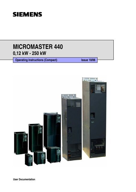
<strong>MICROM<strong>AS</strong>TER</strong> <strong>440</strong><br />
0,12 kW - 250 kW<br />
Operating Instructions (Compact) Issue 10/06<br />
User Documentation
Warnings, Cautions and Notes Issue 10/06<br />
Warnings, Cautions and Notes<br />
The following Warnings, Cautions and Notes are provided for your safety and as a<br />
means of preventing damage to the product or components in the machines<br />
connected. Specific Warnings, Cautions and Notes that apply to particular<br />
activities are listed at the beginning of the relevant chapters and are repeated or<br />
supplemented at critical points throughout these sections. Please read the<br />
information carefully, since it is provided for your personal safety and will also help<br />
prolong the service life of your <strong>MICROM<strong>AS</strong>TER</strong> <strong>440</strong> Inverter and the equipment<br />
you connect to it.<br />
WARNING<br />
‣ This equipment contains dangerous voltages and controls potentially dangerous<br />
rotating mechanical parts. Non-compliance with Warnings or failure to follow<br />
the instructions contained in this manual can result in loss of life, severe<br />
personal injury or serious damage to property.<br />
‣ Only suitable qualified personnel should work on this equipment, and only after<br />
becoming familiar with all safety notices, installation, operation and<br />
maintenance procedures contained in this manual. The successful and safe<br />
operation of this equipment is dependent upon its proper handling, installation,<br />
operation and maintenance.<br />
‣ The DC link capacitors remain charged for five minutes after power has been<br />
removed. It is not permissible to open the equipment until 5 minutes after the<br />
power has been removed. The drive unit discharges itself during this time.<br />
‣ This equipment is capable of providing internal motor overload protection in<br />
accordance with UL508C section 42. Refer to P0610 and P0335, i 2 t is ON by<br />
default. Motor overload protection can also be provided using an external PTC<br />
or KTY84.<br />
‣ This equipment is suitable for use in a circuit capable of delivering not more<br />
than symmetrical 10 kA (rms) (Frame Sizes A to C) or symmetrical 42 kA (rms)<br />
(Frame Sizes D to GX), for a maximum voltage of 230 V / 460 V / 575 V when<br />
protected by an H, J or K type fuse, a circuit breaker or self-protected<br />
combination motor controller (for more details see Operating Instructions<br />
Appendix F).<br />
‣ Use Class 1 60/75 °C copper wire only with the cross-sections as specified in<br />
the Operating Instructions.<br />
‣ The mains input, DC and motor terminals, can carry dangerous voltages even if<br />
the inverter is inoperative. Always wait 5 minutes to allow the unit to discharge<br />
after switching off before carrying out any installation work.<br />
NOTE<br />
‣ Before installing and commissioning, please read these safety instructions and<br />
warnings carefully and all the warning labels attached to the equipment.<br />
‣ Please ensure that all of the warning labels are kept in a condition so that they<br />
can be easily read and replace missing or damaged labels.<br />
‣ Maximum permissible surrounding ambient temperature is:<br />
− Frame Sizes A-F:<br />
50 °C at constant torque (CT) and 100 % permissible output current<br />
40 °C at variable torque (VT) and 100 % permissible output current<br />
− Frame Sizes FX and GX:<br />
40 °C at 100 % permissible output current<br />
<strong>MICROM<strong>AS</strong>TER</strong> <strong>440</strong><br />
2 Operating Instructions (Compact)
Issue 10/06<br />
Contents<br />
Contents<br />
1 Installation ............................................................................................................... 5<br />
1.1 Clearance distances for mounting ............................................................................ 5<br />
1.2 Mounting dimensions................................................................................................ 5<br />
2 Electrical Installation.............................................................................................. 6<br />
2.1 Technical Specifications ........................................................................................... 6<br />
2.2 Power Terminals..................................................................................................... 13<br />
2.3 Control terminals..................................................................................................... 21<br />
2.4 Block diagram ......................................................................................................... 22<br />
3 Factory setting ...................................................................................................... 23<br />
3.1 50/60 Hz DIP switch................................................................................................ 23<br />
4 Communications................................................................................................... 24<br />
4.1 Establishing communications <strong>MICROM<strong>AS</strong>TER</strong> <strong>440</strong> ⇔ STARTER........................ 24<br />
4.2 Establishing communications <strong>MICROM<strong>AS</strong>TER</strong> <strong>440</strong> ⇔ AOP................................. 24<br />
4.3 Bus interface (CB)................................................................................................... 25<br />
5 BOP / AOP (Option) .............................................................................................. 26<br />
5.1 Buttons and their Functions .................................................................................... 26<br />
5.2 Changing parameters using as an example P0004 "Parameter filter function"...... 27<br />
6 Commissioning ..................................................................................................... 28<br />
6.1 Quick commissioning.............................................................................................. 28<br />
6.2 Motor data identification.......................................................................................... 32<br />
6.3 Magnetizing current ................................................................................................ 32<br />
6.4 Commissioning the application ............................................................................... 34<br />
6.4.1 Serial Interface (USS)............................................................................................. 34<br />
6.4.2 Selection of command source ................................................................................ 34<br />
6.4.3 Digital input (DIN).................................................................................................... 35<br />
6.4.4 Digital outputs (DOUT) ........................................................................................... 36<br />
6.4.5 Selection of frequency setpoint............................................................................... 37<br />
6.4.6 Analog input (ADC)................................................................................................. 38<br />
6.4.7 Analog output (DAC)............................................................................................... 39<br />
6.4.8 Motor potentiometer (MOP) .................................................................................... 40<br />
6.4.9 Fixed frequency (FF)............................................................................................... 41<br />
6.4.10 JOG......................................................................................................................... 42<br />
6.4.11 Ramp function generator (RFG) ............................................................................. 43<br />
6.4.12 Reference/limit frequencies .................................................................................... 44<br />
6.4.13 Inverter protection................................................................................................... 45<br />
6.4.14 Motor protection...................................................................................................... 45<br />
6.4.15 Encoder................................................................................................................... 47<br />
6.4.16 V/f control................................................................................................................ 48<br />
<strong>MICROM<strong>AS</strong>TER</strong> <strong>440</strong><br />
Operating Instructions (Compact) 3
Contents Issue 10/06<br />
6.4.17 Field-orientated control ........................................................................................... 50<br />
6.4.17.1 Sensorless vector control (SLVC)........................................................................... 51<br />
6.4.17.2 Vector control with encoder (VC)............................................................................ 53<br />
6.4.18 Converter-specific Functions .................................................................................. 55<br />
6.4.18.1 Flying start .............................................................................................................. 55<br />
6.4.18.2 Automatic restart..................................................................................................... 55<br />
6.4.18.3 Holding brake.......................................................................................................... 56<br />
6.4.18.4 DC brake................................................................................................................. 58<br />
6.4.18.5 Compound braking.................................................................................................. 59<br />
6.4.18.6 Dynamic braking ..................................................................................................... 60<br />
6.4.18.7 Vdc controller .......................................................................................................... 60<br />
6.4.18.8 Load torque monitoring........................................................................................... 61<br />
6.4.18.9 PID controller .......................................................................................................... 63<br />
6.4.18.10 Positioning down ramp ........................................................................................... 66<br />
6.4.18.11 Free function blocks (FFB) ..................................................................................... 67<br />
6.4.19 Data sets................................................................................................................. 69<br />
6.4.20 Diagnostic parameters............................................................................................ 72<br />
6.5 Series commissioning............................................................................................. 75<br />
6.6 Parameter reset of factory setting........................................................................... 75<br />
7 Displays and messages ....................................................................................... 76<br />
7.1 LED status display .................................................................................................. 76<br />
7.2 Fault messages and Alarm messages.................................................................... 77<br />
<strong>MICROM<strong>AS</strong>TER</strong> <strong>440</strong><br />
4 Operating Instructions (Compact)
Issue 10/06<br />
1 Installation<br />
1 Installation<br />
1.1 Clearance distances for mounting<br />
The inverters can be mounted adjacent to each other. When mounting inverters<br />
one above the other, the specified environmental conditions must not be exceeded.<br />
Independent of this, these minimum distances must be observed.<br />
‣ Frame Size A, B, C<br />
‣ Frame Size D, E<br />
‣ Frame Size F<br />
‣ Frame Size FX, GX<br />
above and below 100 mm<br />
above and below 300 mm<br />
above and below 350 mm<br />
above 250 mm<br />
below 150 mm<br />
in front 40 mm (FX), 50 mm (GX)<br />
1.2 Mounting dimensions<br />
Frame<br />
Size<br />
Drilling Dimensions<br />
Tightening Torque<br />
H<br />
mm (Inch)<br />
W<br />
mm (Inch)<br />
Bolts<br />
Nm<br />
(lbf.in)<br />
H<br />
A 160 (6.30) – 2 x M4<br />
B 174 (6.85) 138 (5.43) 4 x M4<br />
C 204 (8.03) 174 (6.85) 4 x M5<br />
D 486 (19.13) 235 (9.25) 4 x M8<br />
2,5<br />
(22.12)<br />
W<br />
E 616,4<br />
(24.27)<br />
235 (9.25) 4 x M8<br />
F 810 (31.89) 300 (11.81) 4 x M8<br />
3,0<br />
(26.54)<br />
FX 1375,5<br />
(54.14)<br />
GX 1508,5<br />
(59.38)<br />
250 (9.84) 6 x M8 13,0<br />
(115.02)<br />
250 (9.84) 6 x M8 13,0<br />
(115.02)<br />
Fig. 1-1<br />
Mounting dimensions<br />
<strong>MICROM<strong>AS</strong>TER</strong> <strong>440</strong><br />
Operating Instructions (Compact) 5
2 Electrical Installation Issue 10/06<br />
2 Electrical Installation<br />
2.1 Technical Specifications<br />
Input voltage range 1 AC 200 V – 240 V, ± 10 %<br />
(Unfiltered and with built in Class A Filter)<br />
Order No<br />
2AB 11- 12- 13- 15- 17- 21- 21- 22- 23-<br />
6SE6<strong>440</strong>-<br />
2UC 2AA1 5AA1 7AA1 5AA1 5AA1 1BA1 5BA1 2BA1 0CA1<br />
Frame Size A B C<br />
Output Rating (CT)<br />
[kW] 0,12 0,25 0,37 0,55 0,75 1,1 1,5 2,2 3,0<br />
[hp] 0,16 0,33 0,5 0,75 1,0 1,5 2,0 3,0 4,0<br />
Output Power [kVA] 0,4 0,7 1,0 1,3 1,7 2,4 3,2 4,6 6,0<br />
CT Input Current 1) 1,8 3,2 4,6 6,2 8,2 11,0 14,4 20,2 35,5<br />
CT Output Current [A] 0,9 1,7 2,3 3,0 3,9 5,5 7,4 10,4 13,6<br />
Fuse 10 10 10 16 16 20 20 32 40<br />
Recommended 3NA 3803 3803 3803 3805 3805 3807 3807 3812 3817<br />
for UL specified * * * * * * * * *<br />
[mm 2 ] 1,0 1,0 1,0 1,5 1,5 2,5 2,5 4,0 6,0<br />
Input Cable Min.<br />
[AWG] 18 18 18 16 16 14 14 12 10<br />
Input Cable Max.<br />
Output Cable Min.<br />
Output Cable Max.<br />
[mm 2 ] 2,5 2,5 2,5 2,5 2,5 6,0 6,0 6,0 10,0<br />
[AWG] 14 14 14 14 14 10 10 10 8<br />
[mm 2 ] 1,0 1,0 1,0 1,0 1,0 1,0 1,0 1,0 1,5<br />
[AWG] 18 18 18 18 18 18 18 18 16<br />
[mm 2 ] 2,5 2,5 2,5 2,5 2,5 6,0 6,0 6,0 10,0<br />
[AWG] 14 14 14 14 14 10 10 10 8<br />
Weight<br />
[kg] 1,3 1,3 1,3 1,3 1,3 3,4 3,4 3,4 5,7<br />
(with built in filter) [lbs] 2,9 2,9 2,9 2,9 2,9 7,5 7,5 7,5 12,5<br />
Weight (unfiltered)<br />
[kg] 1,3 1,3 1,3 1,3 1,3 3,3 3,3 3,3 5,5<br />
[lbs] 2,9 2,9 2,9 2,9 2,9 7,3 7,3 7,3 12,1<br />
Tightening torques for [Nm] 1,1 1,5 2,25<br />
power terminals [lbf.in] (10) (13,3) (20)<br />
1) Secondary conditions: Input current at the rated operating point - applies for the short-circuit voltage of the line<br />
supply V k = 2 % referred to the rated drive converter power and a rated line supply voltage<br />
of 240 V without line commutating reactor.<br />
* UL listed fuses such as Class NON from Bussmann are required for use in America<br />
<strong>MICROM<strong>AS</strong>TER</strong> <strong>440</strong><br />
6 Operating Instructions (Compact)
Issue 10/06<br />
2 Electrical Installation<br />
Input voltage range 3 AC 200 V – 240 V. ± 10 %<br />
(with built in Class A Filter)<br />
Order No. 6SE6<strong>440</strong>- 2AC23-<br />
0CA1<br />
Frame Size<br />
Output Rating(CT)<br />
2AC24-<br />
0CA1<br />
C<br />
2AC25-<br />
5CA1<br />
[kW] 3,0 4,0 5,5<br />
[hp] 4,0 5,0 7,5<br />
Output Power [kVA] 6,0 7,7 9,6<br />
CT Input Current 1) [A] 15,6 19,7 26,5<br />
CT-Output Current [A] 13,6 17,5 22,0<br />
VT Input Current 1) [A] - 28,3 34,2<br />
VT-Output Current [A] - 22,0 28,0<br />
Fuse [A] 25 32 35<br />
Recommended 3NA 3810 3812 3814<br />
For UL specified * * *<br />
Input Cable, min.<br />
Input Cable, max.<br />
Output Cable, min.<br />
Output Cable, max.<br />
[mm 2 ] 2,5 4,0 4,0<br />
[AWG] 14 12 12<br />
[mm 2 ] 10,0 10,0 10,0<br />
[AWG] 8 8 8<br />
[mm 2 ] 1,5 4,0 4,0<br />
[AWG] 16 12 12<br />
[mm 2 ] 10,0 10,0 10,0<br />
[AWG] 8 8 8<br />
Weight<br />
[kg] 5,7 5,7 5,7<br />
[lbs] 12,5 12,5 12,5<br />
Tightening torques for [Nm] 2,25<br />
power terminals [lbf.in] (20)<br />
1) Secondary conditions: Input current at the rated operating point - applies for the short-circuit voltage of the line<br />
supply V k = 2 % referred to the rated drive converter power and a rated line supply voltage<br />
of 240 V without line commutating reactor.<br />
* UL listed fuses such as Class NON from Bussmann are required for use in America<br />
<strong>MICROM<strong>AS</strong>TER</strong> <strong>440</strong><br />
Operating Instructions (Compact) 7
2 Electrical Installation Issue 10/06<br />
Input voltage range 3 AC 200 V – 240 V. ± 10 % (Unfiltered)<br />
Order No. 6SE6<strong>440</strong>- 2UC11<br />
-2AA1<br />
2UC12<br />
-5AA1<br />
2UC13<br />
-7AA1<br />
2UC15<br />
-5AA1<br />
2UC17<br />
-5AA1<br />
2UC21<br />
-1BA1<br />
2UC21<br />
-5BA1<br />
Frame Size A B C<br />
Output Rating(CT)<br />
2UC22<br />
-2BA1<br />
2UC23<br />
-0CA1<br />
[kW] 0,12 0,25 0,37 0,55 0,75 1,1 1,5 2,2 3,0<br />
[hp] 0,16 0,33 0,5 0,75 1,0 1,5 2,0 3,0 4,0<br />
Output Power [kVA] 0,4 0,7 1,0 1,3 1,7 2,4 3,2 4,6 6,0<br />
CT-Input Current 1) [A] 1,1 1,9 2,7 3,6 4,7 6,4 8,3 11,7 15,6<br />
CT-Output Current [A] 0,9 1,7 2,3 3,0 3,9 5,5 7,4 10,4 13,6<br />
Fuse [A] 10 10 10 16 16 20 20 25 25<br />
Recommended 3NA 3803 3803 3803 3805 3805 3807 3807 3810 3810<br />
For UL specified * * * * * * * * *<br />
Input Cable, min.<br />
Input Cable, max.<br />
Output Cable, min.<br />
Output Cable, max.<br />
[mm 2 ] 1,0 1,0 1,0 1,5 1,5 2,5 2,5 2,5 4,0<br />
[AWG] 18 18 18 16 16 14 14 14 12<br />
[mm 2 ] 2,5 2,5 2,5 2,5 2,5 6,0 6,0 6,0 10,0<br />
[AWG] 14 14 14 14 14 10 10 10 8<br />
[mm 2 ] 1,0 1,0 1,0 1,0 1,0 1,0 1,0 1,0 1,5<br />
[AWG] 18 18 18 18 18 18 18 18 16<br />
[mm 2 ] 2,5 2,5 2,5 2,5 2,5 6,0 6,0 6,0 10,0<br />
[AWG] 14 14 14 14 14 10 10 10 8<br />
Weight<br />
[kg] 1,3 1,3 1,3 1,3 1,3 3,3 3,3 3,3 5,5<br />
[lbs] 2,9 2,9 2,9 2,9 2,9 7,3 7,3 7,3 12,1<br />
Tightening torques [Nm] 1,1 1,5 2,25<br />
for power terminals [lbf.in] (10) (13,3) (20)<br />
Order No.<br />
6SE6<strong>440</strong>- 2UC24-<br />
0CA1<br />
2UC25-<br />
5CA1<br />
2UC27-<br />
5DA1<br />
2UC31-<br />
1DA1<br />
2UC31-<br />
5DA1<br />
2UC31-<br />
8EA1<br />
2UC32-<br />
2EA1<br />
2UC33-<br />
0FA1<br />
Frame Size C D E F<br />
2UC33-<br />
7FA1<br />
2UC34-<br />
5FA1<br />
[kW] 4,0 5,5 7,5 11,0 15,0 18,5 22,0 30,0 37,0 45,0<br />
Output Rating(CT)<br />
[hp] 5,0 7,5 10,0 15,0 20,0 25,0 30,0 40,0 50,0 60,0<br />
Output Power [kVA] 7,7 9,6 12,3 18,4 23,7 29,8 35,1 45,6 57,0 67,5<br />
CT-Input Current 1) [A] 19,7 26,5 34,2 38,0 50,0 62,0 71,0 96,0 114,0 135,0<br />
CT-Output Current [A] 17,5 22,0 28,0 42,0 54,0 68,0 80,0 104,0 130,0 154,0<br />
VT-Input Current 1) [A] 28,3 34,2 38,0 50,0 62,0 71,0 96,0 114,0 135,0 164,0<br />
VT-Output Current [A] 22,0 28,0 42,0 54,0 68,0 80,0 104,0 130,0 154,0 -<br />
Fuse [A] 32 35 50 80 80 100 125 200 200 250<br />
Recommended 3NA 3812 3814 3820 3824 3824 3830 3832 3140 3142 3144<br />
For UL specified 3NE * * 1817-0 1820-0 1820-0 1021-0 1022-0 1225-0 1225-0 1227-0<br />
Input Cable, min.<br />
Input Cable, max.<br />
Output Cable, min.<br />
Output Cable, max<br />
Weight<br />
[mm 2 ] 4,0 4,0 10,0 16,0 16,0 25,0 25,0 70,0 70,0 95,0<br />
[AWG] 12 12 8 6 6 3 3 2/0 2/0 3/0<br />
[mm 2 ] 10,0 10,0 35,0 35,0 35,0 35,0 35,0 150,0 150,0 150,0<br />
[AWG] 8 8 2 2 2 2 2 300 300 300<br />
[mm 2 ] 4,0 4,0 10,0 16,0 16,0 25,0 25,0 50,0 70,0 95,0<br />
[AWG] 12 12 8 6 6 3 3 1/0 2/0 3/0<br />
[mm 2 ] 10,0 10,0 35,0 35,0 35,0 35,0 35,0 150,0 150,0 150,0<br />
[AWG] 8 8 2 2 2 2 2 300 300 300<br />
[kg] 5,5 5,5 17,0 16,0 16,0 20,0 20,0 55,0 55,0 55,0<br />
[lbs] 12,1 12,1 37,0 35,0 35,0 44,0 44,0 121,0 121,0 121,0<br />
Tightening torques [Nm] 2,25 10 50<br />
for power terminals [lbf.in] (20) (89) (445)<br />
1) Secondary conditions: Input current at the rated operating point - applies for the short-circuit voltage of the line<br />
supply V k = 2 % referred to the rated drive converter power and a rated line supply voltage<br />
of 240 V without line commutating reactor.<br />
* UL listed fuses such as Class NON from Bussmann are required for use in America<br />
<strong>MICROM<strong>AS</strong>TER</strong> <strong>440</strong><br />
8 Operating Instructions (Compact)
Issue 10/06<br />
2 Electrical Installation<br />
Input voltage range 3 AC 380 V – 480 V. ± 10 %<br />
(with built in Class A Filter)<br />
Order No. 6SE6<strong>440</strong>- 2AD22-<br />
2BA1<br />
2AD23-<br />
0BA1<br />
2AD24-<br />
0BA1<br />
2AD25-<br />
5CA1<br />
2AD27-<br />
5CA1<br />
2AD31-<br />
1CA1<br />
Frame Size B C D<br />
Output Rating(CT)<br />
2AD31-<br />
5DA1<br />
[kW] 2,2 3,0 4,0 5,5 7,5 11,0 15,0<br />
[hp] 3,0 4,0 5,0 7,5 10,0 15,0 20,0<br />
Output Power [kVA] 4,5 5,9 7,8 10,1 14,0 19,8 24,4<br />
CT-Input Current 1) [A] 7,5 10,0 12,8 15,6 22,0 23,1 33,8<br />
CT-Output Current [A] 5,9 7,7 10,2 13,2 18,4 26,0 32,0<br />
VT-Input Current 1) [A] – – – 17,3 23,1 33,8 37,0<br />
VT-Output Current [A] – – – 20,2 29,0 39,0 45,2<br />
Fuse [A] 16 16 20 20 32 35 50<br />
Recommended 3NA 3805 3805 3807 3807 3812 3814 3820<br />
For UL specified 3NE * * * * * * 1817-0<br />
Input Cable, min.<br />
Input Cable, max.<br />
Output Cable, min.<br />
Output Cable, max.<br />
[mm 2 ] 1,5 1,5 2,5 2,5 4,0 6,0 10,0<br />
[AWG] 16 16 14 14 12 10 8<br />
[mm 2 ] 6,0 6,0 6,0 10,0 10,0 10,0 35,0<br />
[AWG] 10 10 10 8 8 8 2<br />
[mm 2 ] 1,0 1,0 1,0 2,5 4,0 6,0 10,0<br />
[AWG] 18 18 18 14 12 10 8<br />
[mm 2 ] 6,0 6,0 6,0 10,0 10,0 10,0 35,0<br />
[AWG] 10 10 10 8 8 8 2<br />
Weight<br />
[kg] 3,4 3,4 3,4 5,7 5,7 5,7 17,0<br />
[lbs] 7,5 7,5 7,5 12,5 12,5 12,5 37,0<br />
Tightening torques for [Nm] 1,1 1,5 2,25<br />
power terminals [lbf.in] (10) (13,3) (20)<br />
Order No. 6SE6<strong>440</strong>- 2AD31-<br />
8DA1<br />
2AD32-<br />
2DA1<br />
2AD33-<br />
0EA1<br />
2AD33-<br />
7EA1<br />
2AD34-<br />
5FA1<br />
Frame Size D E F<br />
2AD35-<br />
5FA1<br />
2AD37-<br />
5FA1<br />
[kW] 18,5 22,0 30,0 37,0 45,0 55,0 75,0<br />
Output Rating(CT)<br />
[hp] 25,0 30,0 40,0 50,0 60,0 75,0 100,0<br />
Output Power [kVA] 29,0 34,3 47,3 57,2 68,6 83,8 110,5<br />
CT-Input Current 1) [A] 37,0 43,0 59,0 72,0 87,0 104,0 139,0<br />
CT-Output Current [A] 38,0 45,0 62,0 75,0 90,0 110,0 145,0<br />
VT-Input Current 1) [A] 43,0 59,0 72,0 87,0 104,0 139,0 169,0<br />
VT-Output Current [A] 45,0 62,0 75,0 90,0 110,0 145,0 178,0<br />
Fuse [A] 63 80 100 125 160 200 250<br />
Recommended 3NA 3822 3824 3830 3832 3836 3140 3144<br />
For UL specified 3NE 1818-0 1820-0 1021-0 1022-0 1224-0 1225-0 1227-0<br />
Input Cable, min.<br />
Input Cable, max.<br />
Output Cable, min.<br />
Output Cable, max.<br />
Weight<br />
[mm 2 ] 10,0 16,0 25,0 25,0 35,0 70,0 95,0<br />
[AWG] 8 6 3 3 2 2/0 3/0<br />
[mm 2 ] 35,0 35,0 35,0 35,0 150,0 150,0 150,0<br />
[AWG] 2 2 2 2 300 300 300<br />
[mm 2 ] 10,0 16,0 25,0 25,0 50,0 70,0 95,0<br />
[AWG] 8 6 3 3 1/0 2/0 3/0<br />
[mm 2 ] 35,0 35,0 35,0 35,0 150,0 150,0 150,0<br />
[AWG] 2 2 2 2 300 300 300<br />
[kg] 17,0 17,0 22,0 22,0 75,0 75,0 75,0<br />
[lbs] 37,0 37,0 48,0 48,0 165,0 165,0 165,0<br />
Tightening torques for [Nm] 10 50<br />
power terminals [lbf.in] (89) (445)<br />
1) Secondary conditions: Input current at the rated operating point - applies for the short-circuit voltage of the line<br />
supply V k = 2 % referred to the rated drive converter power and a rated line supply voltage<br />
of 400 V without line commutating reactor.<br />
* UL listed fuses such as Class NON from Bussmann are required for use in America<br />
<strong>MICROM<strong>AS</strong>TER</strong> <strong>440</strong><br />
Operating Instructions (Compact) 9
2 Electrical Installation Issue 10/06<br />
Input voltage range 3 AC 380 V – 480 V. ± 10 % (Unfiltered)<br />
Order No.<br />
6SE6<strong>440</strong>- 2UD13<br />
-7AA1<br />
2UD15<br />
-5AA1<br />
2UD17<br />
-5AA1<br />
2UD21<br />
-1AA1<br />
2UD21<br />
-5AA1<br />
2UD22<br />
-2BA1<br />
2UD23<br />
-0BA1<br />
2UD24<br />
-0BA1<br />
2UD25<br />
-5CA1<br />
Frame Size A B C<br />
Output Rating(CT)<br />
2UD27<br />
-5CA1<br />
[kW] 0,37 0,55 0,75 1,1 1,5 2,2 3,0 4,0 5,5 7,5<br />
[hp] 0,5 0,75 1,0 1,5 2,0 3,0 4,0 5,0 7,5 10,0<br />
Output Power [kVA] 0,9 1,2 1,6 2,3 3,0 4,5 5,9 7,8 10,1 14,0<br />
CT-Input Current 1) [A] 2,2 2,8 3,7 4,9 5,9 7,5 10,0 12,8 15,6 22,0<br />
CT-Output Current [A] 1,3 1,7 2,2 3,1 4,1 5,9 7,7 10,2 13,2 19,0<br />
VT-Input Current 1) [A] - - - - - - - - 17,3 23,1<br />
VT-Output Current [A] - - - - - - - - 19,0 26,0<br />
Fuse [A] 10 10 10 10 10 16 16 20 20 32<br />
Recommended 3NA 3803 3803 3803 3803 3803 3805 3805 3807 3807 3812<br />
For UL specified * * * * * * * * * *<br />
Input Cable, min.<br />
Input Cable, max.<br />
Output Cable, min.<br />
Output Cable, max.<br />
Weight<br />
[mm 2 ] 1,0 1,0 1,0 1,0 1,0 1,5 1,5 2,5 2,5 4,0<br />
[AWG] 18 18 18 18 18 16 16 14 14 12<br />
[mm 2 ] 2,5 2,5 2,5 2,5 2,5 6,0 6,0 6,0 10,0 10,0<br />
[AWG] 14 14 14 14 14 10 10 10 8 8<br />
[mm 2 ] 1,0 1,0 1,0 1,0 1,0 1,0 1,0 1,0 2,5 4,0<br />
[AWG] 18 18 18 18 18 18 18 18 14 12<br />
[mm 2 ] 2,5 2,5 2,5 2,5 2,5 6,0 6,0 6,0 10,0 10,0<br />
[AWG] 14 14 14 14 14 10 10 10 8 8<br />
[kg] 1,3 1,3 1,3 1,3 1,3 3,3 3,3 3,3 5,5 5,5<br />
[lbs] 2,9 2,9 2,9 2,9 2,9 7,3 7,3 7,3 12,1 12,1<br />
Tightening torques for [Nm] 1,1 1,5 2,25<br />
power terminals [lbf.in] (10) (13,3) (20)<br />
Order No.<br />
6SE6<strong>440</strong>- 2UD31<br />
-1CA1<br />
2UD31<br />
-5DA1<br />
2UD31<br />
-8DA1<br />
2UD32<br />
-2DA1<br />
2UD33<br />
-0EA1<br />
2UD33<br />
-7EA1<br />
2UD34<br />
-5FA1<br />
Frame Size C D E F<br />
Output Rating(CT)<br />
2UD35<br />
-5FA1<br />
2UD37<br />
-5FA1<br />
[kW] 11,0 15,0 18,5 22,0 30,0 37,0 45,0 55,0 75,0<br />
[hp] 15,0 20,0 25,0 30,0 40,0 50,0 60,0 75,0 100,0<br />
Output Power [kVA] 19,8 24,4 29,0 34,3 47,3 57,2 68,6 83,8 110,5<br />
CT-Input Current 1) [A] 23,1 33,8 37,0 43,0 59,0 72,0 87,0 104,0 139,0<br />
CT-Output Current [A] 26,0 32,0 38,0 45,0 62,0 75,0 90,0 110,0 145,0<br />
VT-Input Current 1) [A] 33,8 37,0 43,0 59,0 72,0 87,0 104,0 139,0 169,0<br />
VT-Output Current [A] 32,0 38,0 45,0 62,0 75,0 90,0 110,0 145,0 178,0<br />
Fuse [A] 35 50 63 80 100 125 160 200 250<br />
Recommended 3NA 3814 3820 3822 3824 3830 3832 3836 3140 3144<br />
For UL specified 3NE * 1817-0 1818-0 1820-0 1021-0 1022-0 1224-0 1225-0 1227-0<br />
Input Cable, min.<br />
Input Cable, max.<br />
Output Cable, min.<br />
Output Cable, max.<br />
Weight<br />
[mm 2 ] 6,0 10,0 10,0 16,0 25,0 25,0 35,0 70,0 95,0<br />
[AWG] 10 8 8 6 3 3 2 2/0 3/0<br />
[mm 2 ] 10,0 35,0 35,0 35,0 35,0 35,0 150,0 150,0 150,0<br />
[AWG] 8 2 2 2 2 2 300 300 300<br />
[mm 2 ] 6,0 10,0 10,0 16,0 25,0 25,0 35,0 70,0 95,0<br />
[AWG] 10 8 8 6 3 3 2 2/0 3/0<br />
[mm 2 ] 10,0 35,0 35,0 35,0 35,0 35,0 150,0 150,0 150,0<br />
[AWG] 8 2 2 2 2 2 300 300 300<br />
[kg] 5,5 16,0 16,0 16,0 20,0 20,0 56,0 56,0 56,0<br />
[lbs] 12,1 35,0 35,0 35,0 44,0 44,0 123,0 123,0 123,0<br />
Tightening torques for [Nm] 2,25 10 50<br />
power terminals [lbf.in] (20) (89) (445)<br />
1) Secondary conditions: Input current at the rated operating point - applies for the short-circuit voltage of the line<br />
supply V k = 2 % referred to the rated drive converter power and a rated line supply voltage<br />
of 400 V without line commutating reactor.<br />
* UL listed fuses such as Class NON from Bussmann are required for use in America<br />
<strong>MICROM<strong>AS</strong>TER</strong> <strong>440</strong><br />
10 Operating Instructions (Compact)
Issue 10/06<br />
2 Electrical Installation<br />
Input voltage range 3 AC 380 V – 480 V, ± 10 % (Unfiltered)<br />
Order No. 6SE6<strong>440</strong>- 2UD38-8FA1 2UD41-1FA1 2UD41-3GA1 2UD41-6GA1 2UD42-0GA1<br />
Frame Size FX GX<br />
Output Rating(CT)<br />
[kW] 90 110 132 160 200<br />
[hp] 125 150 200 250 300<br />
Output Power [kVA] 145,4 180 214,8 263,2 339,4<br />
CT-Input Current 1) [A] 169 200 245 297 354<br />
CT-Output Current [A] 178 205 250 302 370<br />
VT-Input Current 1) [A] 200 245 297 354 442<br />
VT-Output Current [A] 205 250 302 370 477<br />
Recommended Fuse<br />
Pipe cable shoe to<br />
DIN 46235<br />
Input Cable, min.<br />
Input Cable, max.<br />
Output Cable, min.<br />
Output Cable, max.<br />
Weight<br />
[A] 250 315 400 450 560<br />
3NE 1227-0 1230-0 1332-0 1333-0 1435-0<br />
[mm] 10 10 10 10 10<br />
[mm 2 ]<br />
[AWG]<br />
or<br />
[kcmil]<br />
[mm 2 ]<br />
[AWG]<br />
or<br />
[kcmil]<br />
[mm 2 ]<br />
[AWG]<br />
or<br />
[kcmil]<br />
[mm 2 ]<br />
[AWG]<br />
or<br />
[kcmil]<br />
1 x 95 or<br />
2 x 35<br />
1 x 4/0 or<br />
2 x 2<br />
1 x 185 or<br />
2 x 120<br />
1 x 350 or<br />
2 x 4/0<br />
1 x 95 or<br />
2 x 35<br />
1 x 4/0 or<br />
2 x 2<br />
1 x 185 or<br />
2 x 120<br />
1 x 350 or<br />
2 x 4/0<br />
1 x 150 or<br />
2 x 50<br />
1 x 300 or<br />
2 x 1/0<br />
1 x 185 or<br />
2 x 120<br />
1 x 350 or<br />
2 x 4/0<br />
1 x 150 or<br />
2 x 50<br />
1 x 300 or<br />
2 x 1/0<br />
1 x 185 or<br />
2 x 120<br />
1 x 350 or<br />
2 x 4/0<br />
1 x 185 or<br />
2 x 70<br />
1 x 400 or<br />
2 x 2/0<br />
1 x 240 or<br />
2 x 70<br />
1 x 500 or<br />
2 x 2/0<br />
2 x 95<br />
2 x 4/0<br />
2 x 240 2 x 240 2 x 240<br />
2 x 400 2 x 400 2 x 400<br />
1 x 185 or<br />
2 x 70<br />
1 x 400 or<br />
2 x 2/0<br />
1 x 240 or<br />
2 x 70<br />
1 x 500 or<br />
2 x 2/0<br />
2 x 95<br />
2 x 4/0<br />
2 x 240 2 x 240 2 x 240<br />
2 x 400 2 x 400 2 x 400<br />
[kg] 110 110 170 170 170<br />
[lbs] 242 242 418 418 418<br />
Tightening torques for [Nm] 25<br />
power terminals [lbf.in] (222,5)<br />
1) Secondary conditions: Input current at the rated operating point - applies for the short-circuit voltage of the line<br />
supply V k ≥ 2.33 % referred to the rated drive converter power and a rated line supply<br />
voltage of 400 V without line commutating reactor.<br />
<strong>MICROM<strong>AS</strong>TER</strong> <strong>440</strong><br />
Operating Instructions (Compact) 11
2 Electrical Installation Issue 10/06<br />
Input voltage range 3 AC 500 V – 600 V, ± 10 % (Unfiltered)<br />
Order No.<br />
6SE6<strong>440</strong>- 2UE17-<br />
5CA1<br />
2UE21-<br />
5CA1<br />
2UE22-<br />
2CA1<br />
2UE24-<br />
0CA1<br />
2UE25-<br />
5CA1<br />
2UE27-<br />
5CA1<br />
2UE31-<br />
1CA1<br />
Frame Size C D<br />
Output Rating(CT)<br />
2UE31-<br />
5DA1<br />
[kW] 0,75 1,5 2,2 4,0 5,5 7,5 11,0 15,0<br />
[hp] 1,0 2,0 3,0 5,0 7,5 10,0 15,0 20,0<br />
Output Power [kVA] 1,3 2,6 3,7 5,8 8,6 10,5 16,2 21,0<br />
CT-Input Current 1) [A] 2,0 3,7 5,3 8,1 11,1 14,4 21,5 24,9<br />
CT-Output Current [A] 1,4 2,7 3,9 6,1 9,0 11,0 17,0 22,0<br />
VT-Input Current 1) [A] 3,2 4,4 6,9 9,4 12,6 18,1 24,9 30,0<br />
VT-Output Current [A] 2,7 3,9 6,1 9,0 11,0 17,0 22,0 27,0<br />
Fuse [A] 10 10 10 16 16 25 32 35<br />
Recommended 3NA 3803-6 3803-6 3803-6 3805-6 3805-6 3810-6 3812-6 3814-6<br />
For UL specified 3NE * * * * * * * 1803-0<br />
Input Cable, min.<br />
Input Cable, max.<br />
Output Cable, min.<br />
Output Cable, max.<br />
Weight<br />
[mm 2 ] 1,0 1,0 1,0 1,5 1,5 2,5 4,0 6,0<br />
[AWG] 18 18 18 16 16 14 12 10<br />
[mm 2 ] 10,0 10,0 10,0 10,0 10,0 10,0 10,0 35,0<br />
[AWG] 8 8 8 8 8 8 8 2<br />
[mm 2 ] 1,0 1,0 1,0 1,0 1,0 2,5 4,0 4,0<br />
[AWG] 18 18 18 18 18 14 12 12<br />
[mm 2 ] 10,0 10,0 10,0 10,0 10,0 10,0 10,0 35,0<br />
[AWG] 8 8 8 8 8 8 8 2<br />
[kg] 5,5 5,5 5,5 5,5 5,5 5,5 5,5 16,0<br />
[lbs] 12,1 12,1 12,1 12,1 12,1 12,1 12,1 35,0<br />
Tightening torques for [Nm] 2,25 10<br />
power terminals [lbf.in] (20) (89)<br />
Order No.<br />
6SE6<strong>440</strong>- 2UE31-<br />
8DA1<br />
2UE32-<br />
2DA1<br />
2UE33-<br />
0EA1<br />
2UE33-<br />
7EA1<br />
2UE34-<br />
5FA1<br />
Frame Size D E F<br />
Output Rating(CT)<br />
2UE35-<br />
5FA1<br />
2UE37-<br />
5FA1<br />
[kW] 18,5 22,0 30,0 37,0 45,0 55,0 75,0<br />
[hp] 25,0 30,0 40,0 50,0 60,0 75,0 100,0<br />
Output Power [kVA] 25,7 30,5 39,1 49,5 59,1 73,4 94,3<br />
CT-Input Current 1) [A] 30,0 35,0 48,0 58,0 69,0 83,0 113,0<br />
CT-Output Current [A] 27,0 32,0 41,0 52,0 62,0 77,0 99,0<br />
VT-Input Current 1) [A] 35,0 48,0 58,0 69,0 83,0 113,0 138,0<br />
VT-Output Current [A] 32,0 41,0 52,0 62,0 77,0 99,0 125,0<br />
Fuse [A] 50 63 80 80 125 160 160<br />
Recommended 3NA 3820-6 3822-6 3824-6 3824-6 3132-6 3136-6 3136-6<br />
For UL specified 3NE 1817-0 1818-0 1820-0 1820-0 1022-0 1224-0 1224-0<br />
Input Cable, min.<br />
Input Cable, max.<br />
Output Cable, min.<br />
Output Cable, max.<br />
Weight<br />
[mm 2 ] 10,0 10,0 16,0 25,0 25,0 50,0 50,0<br />
[AWG] 8 8 6 3 3 1/0 1/0<br />
[mm 2 ] 35,0 35,0 35,0 35,0 150,0 150,0 150,0<br />
[AWG] 2 2 2 2 300 300 300<br />
[mm 2 ] 6,0 10,0 16,0 16,0 25,0 35,0 50,0<br />
[AWG] 10 8 6 6 3 2 1/0<br />
[mm 2 ] 35,0 35,0 35,0 35,0 150,0 150,0 150,0<br />
[AWG] 2 2 2 2 300 300 300<br />
[kg] 16,0 16,0 20,0 20,0 56,0 56,0 56,0<br />
[lbs] 35,0 35,0 44,0 44,0 123,0 123,0 123,0<br />
Tightening torques for [Nm] 10 50<br />
power terminals [lbf.in] (89) (445)<br />
1) Secondary conditions: Input current at the rated operating point - applies for the short-circuit voltage of the line<br />
supply V k = 2 % referred to the rated drive converter power and a rated line supply voltage<br />
of 500 V without line commutating reactor.<br />
* UL listed fuses such as Class NON from Bussmann are required for use in America<br />
<strong>MICROM<strong>AS</strong>TER</strong> <strong>440</strong><br />
12 Operating Instructions (Compact)
Issue 10/06<br />
2 Electrical Installation<br />
2.2 Power Terminals<br />
Frame Size A<br />
You can gain access to the mains and motor terminals by removing the front<br />
covers.<br />
‣ Frame Size A (Fig. 2-1)<br />
‣ Frame Sizes B and C (Fig. 2-2)<br />
‣ Frame sizes D and E (Fig. 2-3)<br />
‣ Frame Size F (Fig. 2-4)<br />
‣ Frame Sizes FX and GX (Fig. 2-5)<br />
‣ Connection terminals for Frame Sizes A - F (Fig. 2-6)<br />
‣ Connection overview for Frame Size FX (Fig. 2-7)<br />
‣ Connection overview for Frame Size GX (Fig. 2-8)<br />
1 2<br />
3 4<br />
Fig. 2-1 Removing front covers (Frame Size A)<br />
<strong>MICROM<strong>AS</strong>TER</strong> <strong>440</strong><br />
Operating Instructions (Compact) 13
2 Electrical Installation Issue 10/06<br />
Frame Sizes B and C<br />
<br />
!<br />
"<br />
# $<br />
Fig. 2-2 Removing front covers (Frame Sizes B and C)<br />
<strong>MICROM<strong>AS</strong>TER</strong> <strong>440</strong><br />
14 Operating Instructions (Compact)
Issue 10/06<br />
2 Electrical Installation<br />
Frame Sizes D and E<br />
1<br />
2<br />
3<br />
Fig. 2-3 Removing front covers (Frame Sizes D and E)<br />
<strong>MICROM<strong>AS</strong>TER</strong> <strong>440</strong><br />
Operating Instructions (Compact) 15
2 Electrical Installation Issue 10/06<br />
Frame Size F<br />
1<br />
2<br />
19 mm AF<br />
3<br />
Fig. 2-4 Removing front covers (Frame Size F)<br />
<strong>MICROM<strong>AS</strong>TER</strong> <strong>440</strong><br />
16 Operating Instructions (Compact)
Issue 10/06<br />
2 Electrical Installation<br />
Frame Sizes FX and GX<br />
1 2<br />
3 4<br />
Fig. 2-5<br />
Removing front covers (Frame Sizes FX and GX)<br />
<strong>MICROM<strong>AS</strong>TER</strong> <strong>440</strong><br />
Operating Instructions (Compact) 17
2 Electrical Installation Issue 10/06<br />
Access to the power supply and motor terminals is possible by removing the front<br />
covers.<br />
Fig. 2-6<br />
Connection terminals for Frame Sizes A - F<br />
<strong>MICROM<strong>AS</strong>TER</strong> <strong>440</strong><br />
18 Operating Instructions (Compact)
Issue 10/06<br />
2 Electrical Installation<br />
Hoisting eyes<br />
Shield connection<br />
Mains cable PE<br />
Cable opening for<br />
mains conection<br />
U1/L1, V1/L2, W1/L3<br />
Cable opening DCPA, DCNA<br />
for connection of an<br />
external braking unit<br />
Mains cable<br />
Phase U1/L1, V1/L2, W1/L3<br />
Connection to<br />
Y-Capacitor<br />
Connection DCPA, DCNA<br />
for external braking unit<br />
Top adjustment rail<br />
Top retaining screw<br />
Connection for dv/dt filter<br />
DCPS, DCNS<br />
Status Display Panel<br />
Elektronic box<br />
Bottom adjustment rail<br />
Bottom retaining screw<br />
Fan screws<br />
Fan<br />
Shield connection<br />
control leads<br />
Fan fuses<br />
Transformer adaption<br />
Motor cable<br />
Phase U2, V2, W2<br />
Motor cable<br />
PE Shield connection<br />
Fig. 2-7<br />
Connection overview for Frame Size FX<br />
<strong>MICROM<strong>AS</strong>TER</strong> <strong>440</strong><br />
Operating Instructions (Compact) 19
2 Electrical Installation Issue 10/06<br />
Hoisting eyes<br />
Shield connection<br />
Mains cable PE<br />
Cable opening for<br />
mains conection<br />
U1/L1, V1/L2, W1/L3<br />
Cable opening DCPA, DCNA<br />
for connection of an<br />
external braking unit<br />
Mains cable<br />
Phase U1/L1, V1/L2, W1/L3<br />
Connection to<br />
Y-Capacitor<br />
Connection DCPA, DCNA<br />
for external braking unit<br />
Top adjustment rail<br />
Top retaining screw<br />
Connection for dv/dt filter<br />
DCPS, DCNS<br />
Status Display Panel<br />
Elektronic box<br />
Bottom adjustment rail<br />
Bottom retaining screw<br />
Fan screws<br />
Fan<br />
Shield connection<br />
control leads<br />
Fan fuses<br />
Transformer adaption<br />
Motor cable<br />
Phase U2, V2, W2<br />
Motor cable<br />
PE Shield connection<br />
Fig. 2-8<br />
Connection overview for Frame Size GX<br />
<strong>MICROM<strong>AS</strong>TER</strong> <strong>440</strong><br />
20 Operating Instructions (Compact)
Issue 10/06<br />
2 Electrical Installation<br />
2.3 Control terminals<br />
Terminal Designation Function<br />
1 – Output +10 V<br />
2 – Output 0 V<br />
3 ADC1+ Analog input 1 (+)<br />
4 ADC1– Analog input 1 (–)<br />
5 DIN1 Digital input 1<br />
6 DIN2 Digital input 2<br />
7 DIN3 Digital input 3<br />
8 DIN4 Digital input 4<br />
9 – Isolated output +24 V / max. 100 mA<br />
10 ADC2+ Analog input 2 (+)<br />
11 ADC2– Analog input 2 (–)<br />
12 DAC1+ Analog output 1 (+)<br />
13 DAC1– Analog output 1 (–)<br />
14 PTCA Connection for PTC / KTY84<br />
15 PTCB Connection for PTC / KTY84<br />
16 DIN5 Digital input 5<br />
17 DIN6 Digital input 6<br />
18 DOUT1/NC Digital output 1 / NC contact<br />
19 DOUT1/NO Digital output 1 / NO contact<br />
20 DOUT1/COM Digital output 1 / Changeover contact<br />
21 DOUT2/NO Digital output 2 / NO contact<br />
22 DOUT2/COM Digital output 2 / Changeover contact<br />
23 DOUT3/NC Digital output 3 / NC contact<br />
24 DOUT3/NO Digital output 3 / NO contact<br />
25 DOUT3/COM Digital output 3 / Changeover contact<br />
26 DAC2+ Analog output 2 (+)<br />
27 DAC2– Analog output 2 (–)<br />
28 – Isolated output 0 V / max. 100 mA<br />
29 P+ RS485 port<br />
30 N– RS485 port<br />
Fig. 2-9 Control terminals of <strong>MICROM<strong>AS</strong>TER</strong> <strong>440</strong><br />
<strong>MICROM<strong>AS</strong>TER</strong> <strong>440</strong><br />
Operating Instructions (Compact) 21
Jog<br />
2 Electrical Installation Issue 10/06<br />
2.4 Block diagram<br />
PE<br />
1/3 AC 200 - 240 V<br />
3 AC 380 - 480 V<br />
3 AC 500 - 600 V<br />
SI<br />
External 24 V<br />
+<br />
_ 24 V<br />
DIN1<br />
DIN2<br />
DIN3<br />
DIN4<br />
DIN5<br />
DIN6<br />
≥ 4.7 kΩ<br />
5<br />
6<br />
7<br />
8<br />
16<br />
17<br />
28<br />
Motor<br />
PTC<br />
KTY84<br />
0 - 20 mA<br />
max. 500 Ω<br />
PNP<br />
or<br />
NPN<br />
DC-<br />
1<br />
2<br />
ADC1+<br />
3<br />
ADC1-<br />
4<br />
ADC2+<br />
10<br />
ADC2-<br />
11<br />
DIN1<br />
5<br />
DIN2<br />
6<br />
DIN3<br />
7<br />
DIN4<br />
8<br />
DIN5<br />
16<br />
DIN6<br />
17<br />
9<br />
28<br />
PTCA<br />
14<br />
PTCB<br />
15<br />
DAC1+<br />
12<br />
DAC1-<br />
13<br />
+10 V<br />
0 V<br />
A/D<br />
A/D<br />
Opto Isolation<br />
Output +24 V<br />
max. 100 mA<br />
(isolated)<br />
Output 0 V<br />
max. 100 mA<br />
(isolated)<br />
A/D<br />
D/A<br />
CPU<br />
BOP link<br />
Frame sizes<br />
A to F<br />
Frame sizes<br />
FX and GX<br />
RS232<br />
Hz150.00<br />
I<br />
0<br />
Fn<br />
P<br />
BOP/AOP<br />
=<br />
PE<br />
~<br />
L/L1, N/L2<br />
or<br />
L/L1, N/L2,L3<br />
or<br />
L1, L2, L3<br />
=<br />
DCNA<br />
DCPA<br />
B+/DC+<br />
B-<br />
DCNS<br />
DCPS<br />
R<br />
External braking<br />
module connection<br />
Connection for<br />
dv/dt filter<br />
0 - 20 mA<br />
max. 500 Ω<br />
DAC2+<br />
26<br />
DAC2-<br />
27<br />
D/A<br />
3 ~<br />
Relay1<br />
COM<br />
20<br />
NO<br />
19<br />
NC<br />
18<br />
60 Hz<br />
Not<br />
used<br />
50 Hz<br />
1 2<br />
DIP switch<br />
(on Control Board)<br />
30 V DC / 5 A (resistive)<br />
250 V AC / 2 A (inductive)<br />
Relay2<br />
Relay3<br />
COM<br />
22<br />
NO<br />
21<br />
COM<br />
25<br />
NO<br />
24<br />
NC<br />
23<br />
0 - 20 mA<br />
current<br />
0 - 10 V<br />
voltage<br />
ADC ADC<br />
1 2<br />
1 2<br />
DIP switch<br />
(on I/O Board)<br />
P+<br />
29<br />
N-<br />
30<br />
RS485<br />
COM link<br />
CB<br />
Option<br />
automatic<br />
PE<br />
M<br />
U,V,W<br />
Fig. 2-10<br />
Block diagram<br />
<strong>MICROM<strong>AS</strong>TER</strong> <strong>440</strong><br />
22 Operating Instructions (Compact)
Issue 10/06<br />
3 Factory setting<br />
3 Factory setting<br />
The <strong>MICROM<strong>AS</strong>TER</strong> <strong>440</strong> frequency inverter is set in the factory so that it can be<br />
operated without any additional parameterization. To do this, the motor parameters<br />
set in the factory (P0304, P0305, P0307, P0310), that correspond to a 4-pole 1LA7<br />
<strong>Siemens</strong> motor, must match the rated data of the connected motor (refer to the<br />
rating plate).<br />
Further factory setting:<br />
‣ Command sources P0700 = 2 (Digital input, see Fig. 3-1)<br />
‣ Setpoint source P1000 = 2 (Analog input, see Fig. 3-1)<br />
‣ Motor cooling<br />
P0335 = 0<br />
‣ Motor current limit<br />
P0640 = 150 %<br />
‣ Min. frequency<br />
P1080 = 0 Hz<br />
‣ Max. frequency<br />
P1082 = 50 Hz<br />
‣ Ramp-up time<br />
P1120 = 10 s<br />
‣ Ramp-down time<br />
P1121 = 10 s<br />
‣ Control mode<br />
P1300 = 0<br />
Analog output<br />
Fig. 3-1<br />
Pre-assignment of the inputs<br />
Input/Output Terminals Parameter Function<br />
Digital input 1 5 P0701 = 1 ON / OFF1 (I/O)<br />
Digital input 2 6 P0702 = 12 Reversing ( )<br />
Digital input 3 7 P0703 = 9 Fault acknowledge (Ack)<br />
Digital input 4 8 P0704 = 15 Fault acknowledge<br />
Digital input 5 16 P0705 = 15 Fixed setpoint (direct)<br />
Digital input 6 17 P0706 = 15 Fixed setpoint (direct)<br />
Digital input 7 Via ADC1 P0707 = 0 Fixed setpoint (direct)<br />
Digital input 8 Via ADC2 P0708 = 0 Digital input disabled<br />
3.1 50/60 Hz DIP switch<br />
The default motor base frequency<br />
of the <strong>MICROM<strong>AS</strong>TER</strong> inverter is<br />
50 Hz. For motors, which are<br />
designed for a base frequency of<br />
60 Hz, the inverters can be set to<br />
this frequency using the DIP50/60<br />
switch.<br />
‣ OFF position:<br />
European defaults (Rated<br />
motor frequency = 50 Hz,<br />
Power in kW etc.)<br />
‣ ON position:<br />
North American defaults<br />
(Rated motor frequency = 60 Hz, Power in hp etc.)<br />
Remove I/O board<br />
DIP50/60<br />
<strong>MICROM<strong>AS</strong>TER</strong> <strong>440</strong><br />
Operating Instructions (Compact) 23
4 Communications Issue 10/06<br />
4 Communications<br />
4.1 Establishing communications<br />
<strong>MICROM<strong>AS</strong>TER</strong> <strong>440</strong> ⇔ STARTER<br />
The following optional components are additionally required in order to establish<br />
communications between STARTER and <strong>MICROM<strong>AS</strong>TER</strong> <strong>440</strong>:<br />
‣ PC frequency inverter connecting set<br />
‣ BOP if the USS standard values (refer to Section 6.4.1 "Serial Interface (USS)")<br />
are changed in the <strong>MICROM<strong>AS</strong>TER</strong> <strong>440</strong> frequency inverter<br />
PC frequency inverter connecting set <strong>MICROM<strong>AS</strong>TER</strong> <strong>440</strong><br />
USS settings, refer to 6.4.1 "Serial<br />
Interface (USS)"<br />
STARTER<br />
Menu, Options --> Set PG/PC interface<br />
--> Select "PC COM-Port (USS)" --><br />
Properties --> Interface "COM1", select<br />
a baud rate<br />
NOTE<br />
The USS parameter settings in the<br />
<strong>MICROM<strong>AS</strong>TER</strong> <strong>440</strong> frequency inverter<br />
and the settings in STARTER must<br />
match!<br />
4.2 Establishing communications<br />
<strong>MICROM<strong>AS</strong>TER</strong> <strong>440</strong> ⇔ AOP<br />
‣ Communications between AOP and MM<strong>440</strong> are based on the USS protocol,<br />
analog to STARTER and MM<strong>440</strong>.<br />
‣ Contrary to the BOP, the appropriate communication parameters - both for the<br />
MM<strong>440</strong> as well as for AOP - should be set if the automatic interface detection<br />
was not carried-out (refer to Table 4-1).<br />
‣ Using the optional components, the AOP can be connected to the<br />
communication interfaces (refer to Table 4-1).<br />
Table 4-1<br />
MM<strong>440</strong> parameters<br />
- baud rate<br />
- bus address<br />
AOP parameters<br />
- baud rate<br />
- bus address<br />
Options<br />
- direct connection<br />
- indirect connection<br />
AOP at the BOP link<br />
P2010[1]<br />
–<br />
P8553<br />
–<br />
No option necessary<br />
BOP/AOP door mounting kit<br />
(6SE6400-0PM00-0AA0)<br />
AOP at the COM link<br />
P2010[0]<br />
P2011<br />
P8553<br />
P8552<br />
Not possible<br />
AOP door mounting kit<br />
(6SE6400-0MD00-0AA0)<br />
<strong>MICROM<strong>AS</strong>TER</strong> <strong>440</strong><br />
24 Operating Instructions (Compact)
Issue 10/06<br />
4 Communications<br />
AOP as control unit<br />
Parameter / Terminal AOP on BOP link AOP on COM link<br />
Command source<br />
Frequency setpoint<br />
(MOP)<br />
/<br />
P0700 4 5<br />
P1000 1<br />
P1035 2032.13 (2032.D) 2036.13 (2036.D)<br />
P1036 2032.14 (2032.E) 2036.14 (2036.E)<br />
Output frequency of the MOP higher<br />
Output frequency of the MOP lower<br />
Acknowledge fault<br />
P2104 2032.7 2036.7<br />
• A fault can be acknowledged via the AOP independently of P0700 or P1000.<br />
4.3 Bus interface (CB)<br />
Bus interface (CB)<br />
DeviceNet<br />
CANopen<br />
PROFIBUS<br />
P0918<br />
P0918<br />
P0918 *)<br />
Baud rate is<br />
automatically specified<br />
by the master<br />
P2040 P2040 P2040<br />
P2041 P2041 P2041<br />
P2051 P2051 P2051<br />
*) DIP switch for addressing the hardware must be observed<br />
DeviceNet CANopen PROFIBUS<br />
P2041[0]<br />
P2041[1]<br />
PZD length<br />
Status/actual value<br />
PZD length<br />
control/setpoint<br />
P2041[2] Baud rate 0: 125 kbaud<br />
1: 250 kbaud<br />
2: 500 kbaud<br />
Data transfer type<br />
from T_PD0_1, T_PD0_5<br />
Data transfer type T_PD0_6<br />
R_PD0_1<br />
R_PD0_5<br />
R_PD0_6<br />
Mapping CANopen MM4<br />
P2041[3] Diagnostics Mapping CANopen MM4<br />
P2041[4] _ - response to communication errors<br />
- baud rate<br />
Setting is not<br />
required (only in<br />
special cases).<br />
Refer to the<br />
Operating<br />
Instructions<br />
"PROFIBUS<br />
option module"<br />
<strong>MICROM<strong>AS</strong>TER</strong> <strong>440</strong><br />
Operating Instructions (Compact) 25
5 BOP / AOP (Option) Issue 10/06<br />
BOP / AOP (Option)<br />
Buttons and their Functions<br />
Panel/<br />
Button<br />
Function<br />
Indicates<br />
Status<br />
Start<br />
converter<br />
Effects<br />
The LCD displays the settings currently used by the converter.<br />
Pressing the button starts the converter. This button is disabled by default.<br />
Activate the button:<br />
BOP: P0700 = 1 or P0719 = 10 ... 16<br />
AOP: P0700 = 4 or P0719 = 40 ... 46 on BOP link<br />
P0700 = 5 or P0719 = 50 ... 56 on COM link<br />
Stop<br />
converter<br />
OFF1<br />
OFF2<br />
Pressing the button causes the motor to come to a standstill at the<br />
selected ramp down rate.<br />
Activate the button: see button "Start converter"<br />
Pressing the button twice (or once long) causes the motor to coast<br />
to a standstill.<br />
BOP: This function is always enabled<br />
(independent of P0700 or P0719).<br />
Change<br />
direction<br />
Jog motor<br />
Functions<br />
Access<br />
parameters<br />
Increase<br />
value<br />
Decrease<br />
value<br />
Press this button to change the direction of rotation of the motor. Reverse is<br />
indicated by a minus (-) sign or a flashing decimal point. Disabled by default.<br />
Activate the button: see button "Start converter".<br />
In the "Ready to power-on" state, when this key is pressed, the motor starts<br />
and rotates with the pre-set jog frequency. The motor stops when the button<br />
is released. Pressing this button when the motor is running has no effect.<br />
This button can be used to view additional information.<br />
It works by pressing and holding the button. It shows the following, starting<br />
from any parameter during operation:<br />
1. DC link voltage (indicated by d – units V).<br />
2. output current. (A)<br />
3. output frequency (Hz)<br />
4. output voltage (indicated by o – units V).<br />
5. The value selected in P0005 (If P0005 is set to show any of the above<br />
(1 - 4) then this will not be shown again).<br />
Additional presses will toggle around the above displays.<br />
Jump Function<br />
From any parameter (rxxxx or Pxxxx) a short press of the Fn button will<br />
immediately jump to r0000, you can then change another parameter, if<br />
required. Upon returning to r0000, pressing the Fn button will return you to<br />
your starting point.<br />
Acknowledgement<br />
If alarm and fault messages are present, then these can be acknowledged by<br />
pressing key Fn.<br />
Pressing this button allows access to the parameters.<br />
Pressing this button increases the displayed value.<br />
Pressing this button decreases the displayed value.<br />
+ AOP menu Calls the AOP menu prompting (this is only available for AOP).<br />
<strong>MICROM<strong>AS</strong>TER</strong> <strong>440</strong><br />
26 Operating Instructions (Compact)
Issue 10/06<br />
5 BOP / AOP (Option)<br />
5.2 Changing parameters using as an example P0004<br />
"Parameter filter function"<br />
Step<br />
Result on the display<br />
1 Press in order to access the parameter<br />
2 Press until P0004 is displayed<br />
3 Press in order to reach the parameter value level<br />
4 Press or in order to obtain the required value<br />
5 Press to acknowledge the value and to save the value<br />
6 The user can only see the command parameters.<br />
<strong>MICROM<strong>AS</strong>TER</strong> <strong>440</strong><br />
Operating Instructions (Compact) 27
6 Commissioning Issue 10/06<br />
6 Commissioning<br />
6.1 Quick commissioning<br />
P0100 = 1, 2<br />
START<br />
The frequency inverter is adapted to the motor using the quick commissioning<br />
function and important technological parameters are set. The quick commissioning<br />
shouldn't be carried-out if the rated motor data saved in the frequency inverter<br />
(4-pole 1LA <strong>Siemens</strong> motor, star circuit configuration frequency inverter (FU)-<br />
specific) match the rating plate data.<br />
Parameters, designated with a * offer more setting possibilities than are actually<br />
listed here. Refer to the parameter list for additional setting possibilities.<br />
Factory setting<br />
P0003 = 3 User access level *<br />
1 Standard: Allows access into most frequently used parameters<br />
1<br />
2 Extended: Allows extended access e.g. to inverter I/O functions<br />
3 Expert (For expert use only)<br />
P0004 = 0 Parameter filter *<br />
0 All parameters<br />
2 Inverter<br />
3 Motor<br />
4 Speed sensor<br />
0<br />
P0010 = 1 Commissioning parameter *<br />
0 Ready<br />
0<br />
1 Quick commissioning<br />
30 Factory setting<br />
NOTE<br />
P0010 should be set to 1 in order to parameterize the data of the motor rating<br />
plate.<br />
P0100 =...<br />
P0100 = 0<br />
P0205 =... P0205 =...<br />
P0300 =... P0300 =...<br />
Europe/ North America<br />
(enters the line supply frequency)<br />
0 Europe [kW], frequency default 50 Hz<br />
1 North America [hp], frequency default 60 Hz<br />
2 North America [kW], frequency default 60 Hz<br />
NOTE<br />
For P0100 = 0 or 1, the setting of switch DIP50/60 determines the value of<br />
P0100.<br />
OFF = kW, 50 Hz<br />
ON = hp, 60 Hz<br />
Inverter application (enters the required torque)<br />
0 Constant torque (e.g. compressors, processing machines)<br />
1 Variable torque (e.g. pumps, fans)<br />
NOTE<br />
This parameter is only effective for drive inverters ≥ 5.5 kW / 400 V<br />
Select motor type<br />
1<br />
1 Asynchronous motor (induction motor)<br />
2 Synchronous motor<br />
NOTE<br />
For P0300 = 2 (synchronous motor), only the V/f control types (P1300 < 20) are<br />
permitted.<br />
0<br />
0<br />
<strong>MICROM<strong>AS</strong>TER</strong> <strong>440</strong><br />
28 Operating Instructions (Compact)
Issue 10/06<br />
6 Commissioning<br />
P0304 =... P0304 =... Rated motor voltage FU-spec.<br />
(Nominal motor voltage [V]<br />
from rating plate)<br />
The rated motor voltage on the rating<br />
plate must be checked, regarding the<br />
star/delta circuit configuration to<br />
P0310 P0304<br />
ensure that it matches with the circuit<br />
connection configured at the motor<br />
terminal board<br />
P0305 =... P0305 =... Rated motor current FU-spec.<br />
(Nominal motor current [A]<br />
from rating plate)<br />
P0307 =... P0307 =... Rated motor power FU-spec. P0307 P0305<br />
P0308 P0311<br />
(Nominal motor power [kW/hp]<br />
from rating plate)<br />
Example of a typical motor rating plate<br />
If P0100 = 0 or 2, value will be in kW. (data for a delta circuit configuration).<br />
If P0100 = 1, value will be in in hp.<br />
P0308 =... P0308 =... Rated motor cosPhi<br />
(Nominal motor power factor (cos ϕ) from rating plate)<br />
If the setting is 0, the value is automatically calculated<br />
P0100 = 1,2: P0308 no significance, no entry required.<br />
FU-spec.<br />
P0309 =... P0309 =... Rated motor efficiency<br />
FU-spec.<br />
(Nominal motor efficiency in [%] from rating plate)<br />
Setting 0 causes internal calculation of value.<br />
P0100 = 0: P0309 no significance, no entry required.<br />
P0310 =... Rated motor frequency<br />
(Nominal motor frequency in [Hz] from rating plate)<br />
Pole pair number recalculated automatically if parameter is changed.<br />
50.00 Hz<br />
P0311 =... Rated motor speed<br />
(Nominal motor speed in [rpm] from rating plate)<br />
Setting 0 causes internal calculation of value.<br />
NOTE<br />
FU-spec.<br />
An entry must be made for closed-loop Vector control, V/f control with FCC and<br />
for slip compensation.<br />
P0320 = ... Motor magnetizing current<br />
(this is entered as a % referred to P0305)<br />
Motor magnetizing current as a % relative to P0305 (rated motor current).<br />
0.0<br />
With P0320 = 0, the motor magnetizing current is calculated using P0340 = 1 or<br />
using P3900 = 1 - 3 (end of the quick commissioning) – and is displayed in<br />
parameter r0331.<br />
P0335 =... Motor cooling<br />
(Selects motor cooling system used)<br />
0<br />
0 Self-cooled: Using shaft mounted fan attached to motor<br />
1 Force-cooled: Using separately powered cooling fan<br />
2 Self-cooled and internal fan<br />
3 Force-cooled and internal fan<br />
P0640 =... Motor overload factor<br />
(Motor overload factor in [%] relative to P0305)<br />
150 %<br />
This defines the limit of the maximum output current as a % of the rated motor<br />
current (P0305). This parameter is set, using P0205 for constant torque, to<br />
150 %, and for variable torque, to 110 %.<br />
P0700 =...<br />
Selection of command source<br />
(enters the command source)<br />
0 Factory default setting<br />
1 BOP (keypad)<br />
2 Terminal<br />
4 USS on BOP link<br />
5 USS on COM link (control terminals 29 and 30)<br />
6 CB on COM link (CB = communications module)<br />
2<br />
<strong>MICROM<strong>AS</strong>TER</strong> <strong>440</strong><br />
Operating Instructions (Compact) 29
6 Commissioning Issue 10/06<br />
BOP<br />
Terminals<br />
USS<br />
BOP link<br />
USS<br />
COM link<br />
CB<br />
COM link<br />
P0700 = 2<br />
Sequence control<br />
Setpoint<br />
channel<br />
Motor<br />
control<br />
P1000 =... Selection of frequency setpoint *<br />
(enters the frequency setpoint source)<br />
1 MOP setpoint<br />
2 Analog setpoint<br />
3 Fixed frequency<br />
4 USS on BOP link<br />
5 USS on COM link (control terminals 29 and 30)<br />
6 CB on COM link (CB = communications module)<br />
7 Analog setpoint 2<br />
10 No main setpoint + MOP setpoint<br />
11 MOP setpoint + MOP setpoint<br />
12 Analog setpoint + MOP setpoint<br />
2<br />
P1080 =...<br />
P1082 =...<br />
P1120 =...<br />
P1121 =...<br />
P1135 =...<br />
...<br />
76 CB on COM link + Analog setpoint 2<br />
77 Analog setpoint 2 + Analog setpoint 2<br />
Min. frequency<br />
0.00 Hz<br />
(enters the minimum motor frequency in Hz)<br />
Sets minimum motor frequency at which motor will run irrespective of frequency<br />
setpoint. The value set here is valid for both clockwise and anticlockwise rotation.<br />
Max. frequency<br />
50.00 Hz<br />
(enters the maximum motor frequency in Hz)<br />
Sets maximum motor frequency at which motor will run irrespective of the<br />
frequency setpoint. The value set here is valid for both clockwise and<br />
anticlockwise rotation.<br />
Ramp-up time<br />
10.00 s<br />
(enters the ramp-up time in s)<br />
Time taken for motor to accelerate from standstill up to maximum motor<br />
frequency (P1082) when no rounding is used. If a ramp-up time is parameterized<br />
which is too low, then this can result in alarm A0501 (current limit value) or the<br />
drive inverter being shutdown with fault F0001 (overcurrent).<br />
Ramp-down time<br />
10.00 s<br />
(enters the deceleration time in s)<br />
Time taken for motor to decelerate from maximum motor frequency (P1082) down<br />
to standstill when no rounding is used. If the ramp-down time is parameterized too<br />
low, then this can result in alarms A0501 (current limit value), A0502 (overvoltage<br />
limit value) or the drive inverter being powered-down with fault F0001<br />
(overcurrent) or F0002 (overvoltage).<br />
OFF3 ramp-down time<br />
5.00 s<br />
(enters the fast stop ramp-down time in s)<br />
Enters the time, for example, with which the motor should be braked from the<br />
maximum frequency P1082 down to standstill for an OFF3 command (fast stop).<br />
If the ramp-down time is parameterized too low, then this can result in alarms<br />
A0501 (current limit value), A0502 (overvoltage limit value) or the drive inverter<br />
being shutdown with fault F0001 (overcurrent) or F0002 (overvoltage).<br />
<strong>MICROM<strong>AS</strong>TER</strong> <strong>440</strong><br />
30 Operating Instructions (Compact)
Issue 10/06<br />
6 Commissioning<br />
P1300 =...<br />
P1500 =...<br />
P1910 = ...<br />
P1960 = ...<br />
P3900 = 1<br />
END<br />
Control mode<br />
0<br />
(enters the required control mode)<br />
0 V/f with linear characteristic<br />
1 V/f with FCC<br />
2 V/f with parabolic characteristic<br />
3 V/f with programmable characteristic<br />
5 V/f for textile applications<br />
6 V/f with FCC for textile applications<br />
19 V/f control with independent voltage setpoint<br />
20 Sensorless Vector control<br />
21 Vector control with sensor<br />
22 Sensorless Vector torque-control<br />
23 Vector torque-control with sensor<br />
Selection of torque setpoint *<br />
0<br />
(enters the source for the torque setpoint)<br />
0 No main setpoint<br />
2 Analog setpoint<br />
4 USS on BOP link<br />
5 USS on COM link (control terminals 29 and 30)<br />
6 CB on COM link (CB = communications module)<br />
7 Analog setpoint 2<br />
Select motor data identification *<br />
0<br />
0 Disabled<br />
Speed controller optimization *<br />
0<br />
0 Inhibited<br />
In order to optimize the speed controller, the closed-loop vector control (P1300 =<br />
20 or 21) must be activated. After the optimization has been selected<br />
(P1960 = 1), Alarm A0542 is displayed.<br />
End of quick commissioning<br />
0<br />
(start of the motor calculation)<br />
0 No quick commissioning (no motor calculations)<br />
1 Motor calculation and reset of all of the other parameters, which are not<br />
included in the quick commissioning (attribute "QC" = no), to the factory<br />
setting<br />
2 Motor calculation and reset of the I/O settings to the factory setting<br />
3 Only motor calculation. The other parameters are not reset.<br />
NOTE<br />
For P3900 = 1,2,3 → P0340 is internally set to 1 and the appropriate data<br />
calculated.<br />
End of the quick commissioning/drive setting<br />
If additional functions must be implemented at the drive inverter, please use the<br />
Section "Commissioning the application" (refer to Section 6.4). We recommend<br />
this procedure for drives with a high dynamic response.<br />
<strong>MICROM<strong>AS</strong>TER</strong> <strong>440</strong><br />
Operating Instructions (Compact) 31
6 Commissioning Issue 10/06<br />
6.2 Motor data identification<br />
START<br />
Factory setting<br />
P0625 = Ambient motor temperature (entered in °C)<br />
20 °C<br />
The motor ambient temperature is entered at the instant that motor data is<br />
being determined (factory setting: 20 °C).<br />
| Motor temp. - P0625|<br />
The difference between the motor temperature and the motor ambient<br />
temperature P0625 must lie in the tolerance range of approx. ± 5 °C. If this is<br />
≤ 5 °C <br />
not the case, then the motor data identification routine can only be carried-out<br />
yes no after the motor has cooled down.<br />
Allow the motor<br />
to cool down<br />
P1910 = 1 Select motor data identification with P1910 = 1<br />
p1910 = 1: Identifies the motor parameter with parameter change.<br />
0<br />
A0541<br />
These are accepted and applied to the controller.<br />
When p1910 = 1 is selected, Alarm A0541 (motor data identification active)<br />
is output, and internally p0340 is set to 3.<br />
ON<br />
OFF1<br />
P1910 = 3<br />
A0541<br />
ON<br />
OFF1<br />
END<br />
Starts the motor data identification run with p1910 = 1<br />
The measuring operation is initiated with the continuous (steady-state) ON<br />
command. The motor aligns itself and current flows through it. Diagnostics is<br />
possible using r0069 (CO: Phase current).<br />
After the motor data identification routine has been completed, p1910 is reset<br />
(p1910 = 0, motor data identification routine inhibited) and Alarm A0541 is<br />
cleared (deleted).<br />
In order to set the frequency converter into a defined state, an OFF1 command<br />
must be issued before the next step.<br />
Select motor data identification with P1910 = 3<br />
0<br />
p1910 = 3: Identifies the saturation characteristic with parameter change.<br />
When p1910 = 3 is selected, Alarm A0541 (motor data identification active)<br />
is output and internally, p0340 is set to 2.<br />
Starts the motor data identification run with P1910 = 3<br />
The measuring operation must be started with a continuous ON command.<br />
After the motor identification routine has been completed, p1910 is reset<br />
(p1910 = 0, motor data identification routine inhibited) and Alarm A0541 is<br />
cleared (deleted).<br />
In order to set the frequency converter into a defined state, an OFF1 command<br />
must be issued before the next step.<br />
6.3 Magnetizing current<br />
‣ The value of the magnetizing current r0331/P0320 has a significant influence on<br />
the closed-loop control. This cannot be measured at standstill. This means that<br />
the value is estimated for standard 4-pole 1LA7 <strong>Siemens</strong> standard using the<br />
automatic parameterization P0340=1 (P0320=0; result in r0331).<br />
‣ If the deviation of the magnetizing current is too high, then the values for the<br />
magnetizing reactance and those of the rotor resistance will not be able to be<br />
accurately determined.<br />
‣ Especially for third-party motors it is important that the magnetizing current<br />
that is determined, is carefully checked and if required, appropriately corrected.<br />
<strong>MICROM<strong>AS</strong>TER</strong> <strong>440</strong><br />
32 Operating Instructions (Compact)
Issue 10/06<br />
6 Commissioning<br />
START<br />
The procedure to manually determine the magnetizing current and to re-calculate<br />
the equivalent circuit diagram data when the drive is operated with closed-loop<br />
vector control (P1300 = 20/21) is shown in the following.<br />
Quick<br />
commissioning<br />
no<br />
Motor data<br />
identification<br />
Operation under<br />
no-load conditions<br />
Criterium<br />
fulfilled <br />
yes<br />
Quick commissioning routine<br />
Using the quick commissioning routine the frequency inverter is adapted to the<br />
motor and important technology parameters are set.<br />
Motor data identification routine<br />
Using the motor data identification routine motor equivalent circuit diagram<br />
data is determined using a measuring technique.<br />
Determining the magnetizing current<br />
In order to determine the magnetizing current (P0320/r0331), the motor should<br />
be accelerated up to approximately 80% of its rated speed under no-load<br />
operating conditions.<br />
In so doing, the following conditions must be carefully maintained:<br />
− the vector control must be activated, P1300 = 20.21<br />
− no field weakening (r0056.8 = 0)<br />
− flux setpoint, r1598 = 100 %<br />
− no efficiency optimization, P1580 = 0 %<br />
No-load operation means that the motor is operated without a load (i.e.<br />
no coupled driven machine).<br />
Under steady-state conditions, a current r0027 is obtained that approximately<br />
corresponds to the rated magnetizing current r0331. (the current is always<br />
less than the no-load current for a pure V/f control).<br />
Measuring and entering the magnetizing current and therefore the associated<br />
new calculation of the equivalent circuit diagram data of the motor is an<br />
iterative procedure. It must be repeated at least 2-3 times until the following<br />
criteria are fulfilled:<br />
− The more accurate the value of the magnetizing current that was<br />
entered, the better the flux setpoint (r1598=100%) matches the flux<br />
actual value (r0084=96..104%) of the observer model.<br />
− The output Xm adaptation (r1787) of the observer model should be<br />
as low as possible. Good values lie between 1-5%. The less that the<br />
Xh adaptation of the observer must operate, the sensitivity of the motor<br />
parameters after power failures are that much less sensitive.<br />
NOTE<br />
In order to display r0084 at the BOP/AOP, the LEVEL 4 parameters must be<br />
enabled using service parameter P3950=46.<br />
P0320 = ...<br />
P0340 = 1<br />
Calculating P0320<br />
Now, the new value can be entered in P0320 from the determined fluxgenerating<br />
current component r0029 by applying the following equation.<br />
P0320 = r0029 * 100 / P0305<br />
Calculating the motor parameters<br />
0<br />
0<br />
The values of the motor equivalent circuit diagram data are calculated from the<br />
entered rating plate data. In addition, the parameters of the controls are pre-set<br />
(subsequently optimized) (P0340 = 3).<br />
END<br />
<strong>MICROM<strong>AS</strong>TER</strong> <strong>440</strong><br />
Operating Instructions (Compact) 33
6 Commissioning Issue 10/06<br />
6.4 Commissioning the application<br />
START<br />
An application is commissioned to adapt/optimize the frequency inverter - motor<br />
combination to the particular application. The frequency inverter offers numerous<br />
functions - but not all of these are required for the particular application. These<br />
functions can be skipped when commissioning the application. A large proportion<br />
of the possible functions are described here; refer to the parameter list for<br />
additional functions.<br />
Parameters, designated with a * offer more setting possibilities than are actually<br />
listed here. Refer to the parameter list for additional setting possibilities.<br />
P0003 = 3 User access level *<br />
1 Standard: Allows access into most frequently used parameters<br />
2 Extended: Allows extended access e.g. to inverter I/O functions<br />
3 Expert (For expert use only)<br />
1<br />
6.4.1 Serial Interface (USS)<br />
P2010 =...<br />
P2011 =...<br />
P2012 =...<br />
P2013 =...<br />
USS baud rate<br />
Sets baud rate for USS communication.<br />
USS address<br />
0<br />
Sets unique address for inverter.<br />
USS PZD length<br />
2<br />
Defines the number of 16-bit words in PZD part of USS telegram.<br />
USS PKW length<br />
127<br />
Defines the number of 16-bit words in PKW part of USS telegram.<br />
6<br />
Possible<br />
Settings:<br />
4 2400 Baud<br />
5 4800 Baud<br />
6 9600 Baud<br />
7 19200 Baud<br />
8 38400 Baud<br />
9 57600 Baud<br />
10 76800 Baud<br />
11 93750 Baud<br />
12 115200 Baud<br />
6.4.2 Selection of command source<br />
P0700 =...<br />
Selection of<br />
command source<br />
Selects digital command source.<br />
0 Factory fault setting<br />
1 BOP (keypad)<br />
2 Terminal<br />
4 USS on BOP link<br />
5 USS on COM link<br />
6 CB on COM link<br />
2<br />
BOP<br />
Terminals<br />
USS<br />
BOP link<br />
USS<br />
COM link<br />
CB<br />
COM link<br />
P0700 = 2<br />
Sequence control<br />
Setpoint<br />
channel<br />
Motor<br />
control<br />
<strong>MICROM<strong>AS</strong>TER</strong> <strong>440</strong><br />
34 Operating Instructions (Compact)
Issue 10/06<br />
6 Commissioning<br />
6.4.3 Digital input (DIN)<br />
P0701 = ...<br />
P0702 = ...<br />
P0703 = ...<br />
P0704 = ...<br />
P0705 = ...<br />
P0706 = ...<br />
P0707 = 0<br />
P0708 = 0<br />
P0724 = ...<br />
P0725 = ...<br />
Function digital input 1 1<br />
Terminal 5<br />
1 ON / OFF1<br />
Function digital input 2 12<br />
Terminal 6<br />
12 Reverse<br />
Function digital input 3 9<br />
Terminal 7<br />
9 Fault acknowledge<br />
Function digital input 4 15<br />
Terminal 8<br />
15 Fixed setpoint (Direct selection)<br />
Function digital input 5 15<br />
Terminal 16<br />
15 Fixed setpoint (Direct selection)<br />
Function digital input 6 15<br />
Terminal 17<br />
15 Fixed setpoint (Direct selection)<br />
Function digital input 7<br />
Via analog input, Terminal 3<br />
0 Digital input disabled<br />
Function digital input 8<br />
Via analog input, Terminal 10<br />
0 Digital input disabled<br />
Debounce time for digital inputs<br />
Defines debounce time (filtering time) used for digital inputs.<br />
0 No debounce time<br />
1 2.5 ms debounce time<br />
2 8.2 ms debounce time<br />
3 12.3 ms debounce time<br />
0<br />
0<br />
Possible Settings:<br />
0 Digital input disabled<br />
1 ON / OFF1<br />
2 ON + Reverse / OFF1<br />
3 OFF2 – coast to standstill<br />
4 OFF3 – quick ramp-down<br />
9 Fault acknowledge<br />
10 JOG right<br />
11 JOG left<br />
12 Reverse<br />
13 MOP up (increase frequency)<br />
14 MOP down (decrease frequency)<br />
15 Fixed setpoint (Direct selection)<br />
16 Fixed setpoint (Direct selection + ON)<br />
17 Fixed setpoint (Binary coded selection + ON)<br />
21 Local/remote<br />
25 DC brake enable<br />
29 External trip<br />
33 Disable additional freq setpoint<br />
99 Enable BICO parameterization<br />
ON > 3,9 V, OFF < 1,7 V<br />
DIN7 1<br />
2<br />
3<br />
4<br />
DIN8 1<br />
2<br />
10<br />
11<br />
PNP / NPN digital inputs<br />
1<br />
Change-over (toggles) between high active (PNP) and low active (NPN). This applies to all<br />
digital inputs simultaneously.<br />
0 NPN mode ==> low active<br />
1 PNP mode ==> high active<br />
3<br />
DIN channel (e.g. DIN1 - PNP (P0725 = 1))<br />
Kl.9<br />
P24 (PNP)<br />
Kl.28<br />
0 V (NPN)<br />
24 V<br />
PNP/NPN DIN<br />
0 ... 1<br />
P0725 (1)<br />
Debounce time: DIN<br />
0 ... 3<br />
P0724 (3)<br />
P0701<br />
0<br />
1<br />
0<br />
1<br />
24 V T 0<br />
&<br />
r0722 Pxxxx BI: ...<br />
r0722 .0<br />
CO/BO: Bin.inp.val<br />
Function<br />
0 V<br />
<strong>MICROM<strong>AS</strong>TER</strong> <strong>440</strong><br />
Operating Instructions (Compact) 35
6 Commissioning Issue 10/06<br />
6.4.4 Digital outputs (DOUT)<br />
P0731 = ...<br />
P0732 = ...<br />
P0733 = ...<br />
r0747 = ...<br />
P0748 = ...<br />
BI: Function of digital output 1 *<br />
Defines source of digital output 1.<br />
BI: Function of digital output 2 *<br />
Defines source of digital output 2.<br />
BI: Function of digital output 3 *<br />
Defines source of digital output 3.<br />
52.3<br />
52.7<br />
CO/BO: State of digital outputs<br />
Displays status of digital outputs (also<br />
includes inversion of digital outputs via<br />
P0748).<br />
0.0<br />
Invert digital output<br />
0<br />
Defines high and low states of relay for a<br />
given function.<br />
Common Settings:<br />
Closed<br />
52.0 Drive ready 0<br />
52.1 Drive ready to run 0<br />
52.2 Drive running 0<br />
52.3 Drive fault active 0<br />
52.4 OFF2 active 1<br />
52.5 OFF3 active 1<br />
52.6 Switch on inhibit active 0<br />
52.7 Drive warning active 0<br />
52.8 Deviation setpoint/actual value 1<br />
52.9 PZD control (Process Data Control) 0<br />
52.A Maximum frequency reached 0<br />
52.B Warning: Motor current limit 1<br />
52.C Motor holding brake (MHB) active 0<br />
52.D Motor overload 1<br />
52.E Motor running direction right 0<br />
52.F Inverter overload 1<br />
53.0 DC brake active 0<br />
53.1 Act. freq. f_act > P2167 (f_off) 0<br />
53.2 Act. freq. f_act P2170 0<br />
53.4 Act. freq. f_act > P2155 (f_1) 0<br />
53.5 Act. freq. f_act = setpoint 0<br />
53.7 Act. Vdc r0026 < P2172 0<br />
53.8 Act. Vdc r0026 > P2172 0<br />
53.A PID output<br />
r2294 == P2292 (PID_min) 0<br />
53.B PID output<br />
r2294 == P2291 (PID_max) 0<br />
DOUT channel<br />
Function<br />
xxxx.y<br />
rxxxx.y<br />
BI: Fct. of DOUT 1<br />
P0731.C<br />
(52:3)<br />
P0731 = xxxx.y<br />
Invert DOUTs<br />
0 ... 7<br />
P0748 (0)<br />
0<br />
1<br />
-1<br />
CO/BO: State DOUTs<br />
r0747<br />
r0747.0<br />
int. 24 V<br />
max. 100 mA<br />
Kl.9<br />
COM<br />
NO<br />
NC<br />
Relay : Text<br />
DC 30 V / 5 A<br />
AC 250 V / 2 A<br />
max. opening / closing time<br />
5 / 10 ms<br />
Kl.20<br />
Kl.19<br />
or<br />
Kl.18<br />
Kl.28<br />
<strong>MICROM<strong>AS</strong>TER</strong> <strong>440</strong><br />
36 Operating Instructions (Compact)
Issue 10/06<br />
6 Commissioning<br />
6.4.5 Selection of frequency setpoint<br />
P1000 =...<br />
Selection of frequency setpoint<br />
0 No main setpoint<br />
1 MOP setpoint<br />
2 Analog setpoint<br />
3 Fixed frequency<br />
4 USS on BOP link<br />
5 USS on COM link<br />
6 CB on COM link<br />
7 Analog setpoint 2<br />
10 No main setpoint + MOP setpoint<br />
11 MOP setpoint + MOP setpoint<br />
12 Analog setpoint + MOP setpoint<br />
...<br />
76 CB on COM link + Analog setpoint 2<br />
77 Analog setpoint 2 + Analog setpoint 2<br />
NOTE<br />
In addition to the main setpoint, a supplementary setpoint can be entered using P1000<br />
Example P1000 = 12 :<br />
2<br />
P1000 = 12 ⇒ P1070 = 755<br />
P1000 = 12 ⇒ P1075 = 1050<br />
P1070<br />
r0755<br />
P1075<br />
r1050<br />
CI: Main setpoint<br />
CO: Act. ADC after scal. [4000h]<br />
CI: Additional setpoint<br />
CO: Act. Output freq. of the MOP<br />
MOP<br />
ADC<br />
P1076<br />
P1074<br />
Sequence control<br />
FF<br />
USS<br />
BOP link<br />
USS<br />
COM link<br />
x<br />
P1000 = 12<br />
P1000 = 12<br />
Additonal<br />
setpoint<br />
Main<br />
setpoint<br />
Setpoint<br />
channel<br />
Motor<br />
control<br />
CB<br />
COM link<br />
ADC2<br />
P1074 = ...<br />
P1076 = ...<br />
BI: Disable additional setpoint<br />
Disables additional setpoint (ZUSW).<br />
CI: Additional setpoint scaling<br />
Defines the source to scale the additional setpoint.<br />
Common settings:<br />
1 Scaling of 1.0 (100 %)<br />
755 Analog input setpoint<br />
1024 Fixed frequency setpoint<br />
1050 MOP setpoint<br />
0:0<br />
1:0<br />
<strong>MICROM<strong>AS</strong>TER</strong> <strong>440</strong><br />
Operating Instructions (Compact) 37
6 Commissioning Issue 10/06<br />
6.4.6 Analog input (ADC)<br />
P0756 = ...<br />
ADC type<br />
Defines the analog input type and activates the monitoring<br />
function of the analog input.<br />
0<br />
0 Unipolar voltage input (0 to +10 V)<br />
1 Unipolar voltage input with monitoring ADC1<br />
(0 to 10 V)<br />
2 Unipolar current input (0 to 20 mA)<br />
3 Unipolar current input with monitoring<br />
(0 to 20 mA)<br />
4 Bipolar voltage input (-10 to +10 V)<br />
NOTE<br />
For P0756 to P0760, the following applies:<br />
Index 0 : Analog input 1 (ADC1), terminals 3, 4<br />
Index 1 : Analog input 2 (ADC2), terminals 10, 11<br />
OFF = [V], 0 - 10 V<br />
ON = [A], 0 - 20 mA<br />
ADC2<br />
OFF = [V], 0 - 10 V<br />
ON = [A], 0 - 20 mA<br />
7<br />
P0757 =...<br />
P0758 =...<br />
P0759 =...<br />
Value x1 of ADC scaling<br />
0 V<br />
Value y1 of ADC scaling 0.0 %<br />
This parameter represents the<br />
value of x1 as a % of P2000<br />
(reference frequency).<br />
Value x2 of ADC scaling 10 V<br />
P0761 > 0<br />
0 < P0758 < P0760 || 0 > P0758 > P0760<br />
%<br />
100 %<br />
4000 h<br />
<strong>AS</strong>Pmax<br />
P0760<br />
P0760 =...<br />
P0761 =...<br />
Value y2 of ADC scaling 100.0 %<br />
This parameter represents the<br />
value of x2 as a % of P2000<br />
(reference frequency).<br />
Width of ADC deadband 0 V<br />
Defines width of deadband on<br />
analog input.<br />
P0758<br />
<strong>AS</strong>Pmin<br />
P0761<br />
P0757<br />
P0757 = P0761<br />
P0759<br />
10 V<br />
20 mA<br />
x 100%<br />
V<br />
mA<br />
P0762 = ...<br />
Delay, ADC signal loss<br />
10 ms<br />
Defines the delay time between the loss of the analog setpoint and fault message F0080<br />
being displayed.<br />
ADC channel<br />
KL3<br />
ADC+<br />
KL4<br />
ADC−<br />
DIP switch<br />
ADC<br />
type<br />
A<br />
D<br />
P0756<br />
ADC<br />
type<br />
P0753<br />
P0757<br />
P0758<br />
P0759<br />
P0760<br />
ADC<br />
scaling<br />
r0754<br />
P0761<br />
ADC<br />
dead<br />
zone<br />
P1000<br />
r0755<br />
Setpoint<br />
Pxxxx<br />
P0756<br />
P0761<br />
P0762<br />
r0752<br />
Wire<br />
breakage<br />
sensing<br />
1 1.7 V 0<br />
3.9 V P0707<br />
T 0<br />
r0722<br />
r0722.6<br />
Pxxxx<br />
F0080<br />
r0751<br />
Function<br />
<strong>MICROM<strong>AS</strong>TER</strong> <strong>440</strong><br />
38 Operating Instructions (Compact)
Issue 10/06<br />
6 Commissioning<br />
6.4.7 Analog output (DAC)<br />
P0771 = ...<br />
P0773 =...<br />
P0775 = ...<br />
P0776 = ...<br />
CI: DAC<br />
Defines function of the 0 - 20 mA analog output.<br />
21 CO: Output frequency (scaled according to P2000)<br />
24 CO: Frequency inverter output frequency (scaled according to P2000)<br />
25 CO: Output voltage (scaled according to P2001)<br />
26 CO: DC link voltage (scaled according to P2001)<br />
27 CO: Output current (scaled according to P2002)<br />
NOTE<br />
For P0771 to P0781, the following applies:<br />
Index 0 : Analog output 1 (DAC1), terminals 12, 13<br />
Index 1 : Analog output 2 (DAC2), terminals 26, 27<br />
Smooth time DAC<br />
2 ms<br />
Defines smoothing time [ms] for analog output signal. This parameter enables smoothing<br />
for DAC using a PT1 filter.<br />
Permit absolute value<br />
Decides if the absolute value of the analog output is used. If enabled, this parameter will<br />
take the absolute value of the value to be outputed. If the value was originally negative then<br />
the corresponding bit in r0785 is set, otherwise it is cleared.<br />
0 OFF<br />
1 ON<br />
DAC type<br />
0<br />
Defines the analog output type.<br />
0 Current output<br />
1 Voltage output<br />
NOTE<br />
• P0776 changes the scaling of r0774 (0 – 20 mA ⇔ 0 – 10 V)<br />
• Scaling parameters P0778, P0780 and the dead zone are always entered in 0 – 20 mA<br />
For the DAC as voltage output, the DAC outputs must be terminated using a 500 Ω resistor<br />
21<br />
P0777 = ...<br />
P0778 = ...<br />
P0779 = ...<br />
Value x1 of DAC scaling 0.0 %<br />
Defines the output characteristic value<br />
x1 as a %.<br />
This parameter represents the lowest<br />
analog value as a % of P200x<br />
(depending on the setting of P0771).<br />
Value y1 of DAC scaling 0<br />
This parameter represents the value for<br />
x1 in mA.<br />
Value x2 of DAC scaling 100.0 %<br />
Defines the output characteristic value<br />
x2 as a %.<br />
This parameter represents the lowest<br />
analog value as a % of P200x<br />
(depending on the setting of P0771).<br />
mA<br />
20<br />
P0780<br />
y2<br />
P0781<br />
P0778<br />
y1<br />
P0777<br />
x 1<br />
P0779<br />
x 2<br />
100 %<br />
%<br />
P0780 = ...<br />
Value y2 of DAC scaling<br />
This parameter represents the value for x2 in mA.<br />
20<br />
P0781 = ...<br />
Width of DAC deadband<br />
Sets width of deadband in [mA] for analog output.<br />
0<br />
<strong>MICROM<strong>AS</strong>TER</strong> <strong>440</strong><br />
Operating Instructions (Compact) 39
6 Commissioning Issue 10/06<br />
6.4.8 Motor potentiometer (MOP)<br />
P1031 =...<br />
P1032 =...<br />
P1040 =...<br />
Setpoint memory of the MOP<br />
0<br />
Saves last motor potentiometer setpoint (MOP) that was active before OFF command or<br />
power down.<br />
0 MOP setpoint will not be stored<br />
1 MOP setpoint will be stored (P1040 is updated)<br />
Inhibit negative MOP setpoints<br />
0 Neg. MOP setpoint is allowed<br />
1 Neg. MOP setpoint inhibited<br />
Setpoint of the MOP<br />
Determines setpoint for motor potentiometer control.<br />
MOP ramp-up and ramp-down times are defined by the parameters P1120 and P1121.<br />
Possible parameter settings for the selection of MOP:<br />
1<br />
5.00 Hz<br />
Selection<br />
MOP up<br />
MOP down<br />
DIN<br />
P0719 = 0, P0700 = 2, P1000 = 1<br />
or<br />
P0719 = 1, P0700 = 2<br />
P0702 = 13<br />
(DIN2)<br />
P0703 = 14<br />
(DIN3)<br />
BOP<br />
USS on<br />
BOP link<br />
USS on<br />
COM link<br />
CB<br />
P0719 = 0, P0700 = 1, P1000 = 1<br />
or<br />
P0719 = 11<br />
P0719 = 0, P0700 = 4, P1000 = 1<br />
or<br />
P0719 = 41<br />
P0719 = 0, P0700 = 5, P1000 = 1<br />
or<br />
P0719 = 51<br />
P0719 = 0, P0700 = 6, P1000 = 1<br />
or<br />
P0719 = 61<br />
UP button<br />
USS control word<br />
r2032 Bit13<br />
USS control word<br />
r2036 Bit13<br />
CB control word<br />
r2090 Bit13<br />
DOWN button<br />
USS control word<br />
r2032 Bit14<br />
USS control word<br />
r2036 Bit14<br />
CB control word<br />
r2090 Bit14<br />
<strong>MICROM<strong>AS</strong>TER</strong> <strong>440</strong><br />
40 Operating Instructions (Compact)
Issue 10/06<br />
6 Commissioning<br />
6.4.9 Fixed frequency (FF)<br />
P1001 = ...<br />
P1002 = ...<br />
P1003 = ...<br />
P1004 = ...<br />
P1005 = ...<br />
P1006 = ...<br />
P1007 = ...<br />
P1008 = ...<br />
P1009 = ...<br />
P1010 = ...<br />
Fixed frequency 1<br />
0.00 Hz<br />
Can be directly selected via DIN1<br />
(P0701 = 15, 16)<br />
Fixed frequency 2<br />
5.00 Hz<br />
Can be directly selected via DIN2<br />
(P0702 = 15, 16)<br />
Fixed frequency 3<br />
Can be directly selected via DIN3<br />
(P0703 = 15, 16)<br />
Fixed frequency 4<br />
Can be directly selected via DIN4<br />
(P0704 = 15, 16)<br />
Fixed frequency 5<br />
Can be directly selected via DIN5<br />
(P0705 = 15, 16)<br />
Fixed frequency 6<br />
Can be directly selected via DIN6<br />
(P0706 = 15, 16)<br />
Fixed frequency 7<br />
Fixed frequency 8<br />
Fixed frequency 9<br />
Fixed frequency 10<br />
10.00 Hz<br />
15.00 Hz<br />
20.00 Hz<br />
25.00 Hz<br />
30.00 Hz<br />
35.00 Hz<br />
40.00 Hz<br />
45.00 Hz<br />
When defining the function of the digital inputs<br />
(P0701 to P0703), three different types can be<br />
selected for fixed frequencies:<br />
15 = Direct selection (binary-coded)<br />
In this particular mode, the appropriate<br />
digital input always selects the associated<br />
fixed frequency, e.g.:<br />
Digital input 3 = selects fixed frequency 3.<br />
If several inputs are simultaneously active,<br />
then these are summed. An ON command is<br />
additionally required.<br />
16 = Direct selection + ON command<br />
(binary-coded + On / Off1)<br />
In this mode, the fixed frequencies are<br />
selected as for 15, however these are<br />
combined with an ON command.<br />
17 = Binary coded selection + ON command<br />
(BCD-coded + On/ Off1)<br />
The BCD-coded operating mode is effective for<br />
digital inputs 1 to 3.<br />
P1011 = ...<br />
P1012 = ...<br />
P1013 = ...<br />
P1014 = ...<br />
P1015 = ...<br />
Fixed frequency 11<br />
Fixed frequency 12<br />
Fixed frequency 13<br />
Fixed frequency 14<br />
Fixed frequency 15<br />
50.00 Hz<br />
55.00 Hz<br />
60.00 Hz<br />
65.00 Hz<br />
65.00 Hz<br />
P1016 = ...<br />
P1017 = ...<br />
P1018 = ...<br />
Fixed frequency code - Bit 0 1<br />
Defines the selection method for fixed<br />
frequencies.<br />
Fixed frequency code - Bit 1<br />
Fixed frequency code - Bit 2<br />
1<br />
1<br />
1 Direct selection<br />
2 Direct selection + ON command<br />
3 Binary coded selection + ON command<br />
NOTE<br />
For settings 2 and 3, all parameters P1016 to<br />
P1019 must be set to the selected value so that<br />
the drive inverter accepts the ON command.<br />
P1019 = ...<br />
Fixed frequency code - Bit 3<br />
1<br />
P1025 = ...<br />
P1027 = ...<br />
Fixed frequency code - Bit 4<br />
Fixed frequency code - Bit 5<br />
1<br />
1<br />
1 Direct selection<br />
2 Direct selection + ON command<br />
<strong>MICROM<strong>AS</strong>TER</strong> <strong>440</strong><br />
Operating Instructions (Compact) 41
6 Commissioning Issue 10/06<br />
6.4.10 JOG<br />
P1058 = ...<br />
JOG frequency right<br />
5.00 Hz<br />
Frequency in Hz when the motor is<br />
rotating clockwise in the jog mode.<br />
JOG<br />
P1059 = ...<br />
P1060 = ...<br />
JOG frequency left<br />
5.00 Hz<br />
Frequency in Hz when the motor is<br />
rotating counter-clockwise in the jog<br />
mode.<br />
JOG ramp-up time<br />
10.00 s<br />
Ramp-up time in s from 0 to the<br />
maximum frequency (p1082). JOG rampup<br />
is limited by p1058 or p1059.<br />
p1082<br />
(f max<br />
)<br />
p1058<br />
f<br />
P1061 = ...<br />
JOG ramp-down time<br />
10.00 s<br />
Ramp-down time in s from the maximum<br />
frequency (p1082) to 0.<br />
p1060<br />
p1061<br />
t<br />
A0923<br />
A0923<br />
DIN<br />
BOP<br />
Tippen rechts<br />
P1055<br />
(0)<br />
"1"<br />
"0"<br />
t<br />
USS<br />
BOP link<br />
USS<br />
COM link<br />
CB<br />
COM link<br />
"1"<br />
Tippen links<br />
P1056 "0"<br />
(0)<br />
P1082<br />
P1058<br />
f<br />
t<br />
t<br />
P1059<br />
-P1082<br />
P1060<br />
P1061<br />
P1060<br />
P1061<br />
<strong>MICROM<strong>AS</strong>TER</strong> <strong>440</strong><br />
42 Operating Instructions (Compact)
Issue 10/06<br />
6 Commissioning<br />
6.4.11 Ramp function generator (RFG)<br />
P1091 = ...<br />
P1092 = ...<br />
Skip frequency 1 (entered in Hz) 0.00 Hz<br />
Defines skip frequency 1, which avoids<br />
effects of mechanical resonance and<br />
suppresses frequencies within +/- p1101<br />
(skip frequency bandwidth).<br />
Skip frequency 2<br />
0.00 Hz<br />
f out<br />
P1093 = ...<br />
P1094 = ...<br />
P1101 = ...<br />
Skip frequency 3<br />
Skip frequency 4<br />
Skip frequency bandwidth<br />
(entered in Hz)<br />
0.00 Hz<br />
0.00 Hz<br />
2.00 Hz<br />
p1091<br />
Skip frequency<br />
p1101<br />
Skip frequency<br />
bandwidth<br />
f in<br />
P1120 = ...<br />
Ramp-up time<br />
(enters the accelerating time in s)<br />
10.00 s<br />
p1082<br />
(f max<br />
)<br />
f<br />
f 1<br />
P1121 = ...<br />
Ramp-down time<br />
(enters the deceleration time in s)<br />
10.00 s<br />
p1120<br />
p1121<br />
t<br />
P1130 = ...<br />
P1131 = ...<br />
P1132 = ...<br />
P1133 = ...<br />
P1134 = ...<br />
P1135 = ...<br />
Rump-up initial rounding time<br />
(entered in s)<br />
Ramp-up final rounding time<br />
(entered in s)<br />
Rump-down initial rounding time<br />
(entered in s)<br />
Ramp-down final rounding time<br />
(entered in s)<br />
Rounding type<br />
0 Continuous smoothing<br />
1 Discontinuous smoothing<br />
0.00 s<br />
0.00 s<br />
0.00 s<br />
0.00 s<br />
0<br />
f 2<br />
f<br />
f 1<br />
P1130 P1131<br />
P1132 P1133<br />
t up<br />
t down<br />
The rounding times are recommended as<br />
abrupt responses can be avoided therefore<br />
reducing stress and damage to the mechanical<br />
system.<br />
The ramp-up and ramp-down times are<br />
extended by the component of the rounding<br />
ramps.<br />
OFF3 ramp-down time<br />
Defines ramp-down time from maximum frequency to standstill for OFF3 command.<br />
5.00 s<br />
t<br />
<strong>MICROM<strong>AS</strong>TER</strong> <strong>440</strong><br />
Operating Instructions (Compact) 43
6 Commissioning Issue 10/06<br />
6.4.12 Reference/limit frequencies<br />
P1080 = ...<br />
P1082 = ...<br />
P2000 = ...<br />
P2001 = ...<br />
P2002 = ...<br />
P2003 = ...<br />
Min. frequency (entered in Hz)<br />
0.00 Hz<br />
Sets minimum motor frequency [Hz] at which motor will run irrespective of frequency<br />
setpoint. If the setpoint falls below the value of p1080, then the output frequency is set to<br />
p1080 taking into account the sign.<br />
Max. frequency (entered in Hz)<br />
50.00 Hz<br />
Sets maximum motor frequency [Hz] at which motor will run irrespective of the frequency<br />
setpoint. If the setpoint exceeds the value p1082, then the output frequency is limited. The<br />
value set here is valid for both clockwise and anticlockwise rotation.<br />
Reference frequency (entered in Hz)<br />
50.00 Hz<br />
The reference frequency in Hertz corresponds to a value of 100 %.<br />
This setting should be changed if a maximum frequency of higher than 50 Hz is required.<br />
It is automatically changed to 60 Hz if the standard 60 Hz frequency was selected using<br />
p0100.<br />
NOTE<br />
This reference frequency effects the setpoint frequency as both the frequency setpoints via<br />
USS as well as via PROFIBUS (FB100) (4000H hex 100 % p2000) refer to this value.<br />
Reference voltage (entered in V)<br />
1000 V<br />
The reference voltage in Volt (output voltage) corresponds to a value of 100 %.<br />
NOTE<br />
This setting should only be changed if it is necessary to output the voltage with a different<br />
scaling.<br />
Reference current (entered in A)<br />
0.10 A<br />
The reference current in Amps (output current) corresponds to a value of 100 %. Factory<br />
setting = 200 % of the rated motor current (P0305).<br />
NOTE<br />
This setting should only be changed if it is necessary to output the current with a different<br />
scaling.<br />
Reference torque (entered in Nm)<br />
0.12 Mn<br />
The reference torque in Nm corresponds to a value of 100 %. Factory setting = 200 % of<br />
the rated motor torque at a constant motor torque determined from the appropriate motor<br />
data.<br />
NOTE<br />
This setting should only be changed if it is necessary to output the torque with a different<br />
scaling.<br />
<strong>MICROM<strong>AS</strong>TER</strong> <strong>440</strong><br />
44 Operating Instructions (Compact)
Issue 10/06<br />
6 Commissioning<br />
6.4.13 Inverter protection<br />
P0290 = ...<br />
Inverter overload reaction<br />
Selects reaction of inverter to an internal over-temperature.<br />
0 Reduce output frequency<br />
1 Trip (F0004 / F0005)<br />
2 Reduce pulse frequency and output frequency<br />
3 Reduce pulse frequency then trip (F0004)<br />
Inverter monitoring<br />
Inverter overload reaction<br />
P0290<br />
0<br />
r0036<br />
r0037<br />
i 2 t<br />
P0294<br />
Heat sink<br />
temperature<br />
P0292<br />
IGBT<br />
temperature<br />
P0292<br />
i_max control<br />
(U/f)<br />
Current control<br />
(SLVC, VC)<br />
f_pulse<br />
control<br />
A0504<br />
A0505<br />
A0506<br />
F0004<br />
F0005<br />
P0292 =...<br />
Inverter temperature warning<br />
15 °C<br />
Defines the temperature difference (in ºC) between the Overtemperature trip threshold and<br />
the warning threshold of the inverter. The trip threshold is stored internally by the inverter<br />
and cannot be changed by the user.<br />
Temperature warning threshold of inverter T_warn<br />
T = T - P0292<br />
warn<br />
trip<br />
Temperature shutdown threshold of inverter T_trip<br />
Temperature<br />
Heat sink<br />
A - C<br />
110 °C<br />
D - F<br />
95 °C<br />
MM<strong>440</strong>, Frame Size<br />
F<br />
FX<br />
600 V 95 kW 110 kW 132 kW<br />
CT CT CT<br />
80 °C 88 °C 91 °C 80 °C<br />
GX<br />
160 kW<br />
CT<br />
82 °C<br />
200 kW<br />
CT<br />
88 °C<br />
IGBT<br />
140 °C<br />
145 °C<br />
145 °C<br />
150 °C<br />
150 °C<br />
145 °C<br />
147 °C<br />
150 °C<br />
Input rectifier -<br />
-<br />
-<br />
75 °C<br />
75 °C<br />
75 °C<br />
75 °C<br />
75 °C<br />
Cooling air -<br />
-<br />
-<br />
55 °C<br />
55 °C<br />
55 °C<br />
55 °C<br />
50 °C<br />
Control board -<br />
-<br />
-<br />
65 °C 65 °C<br />
65 °C 65 °C<br />
65 °C<br />
P0295 = ...<br />
Delay, fan shutdown<br />
0 s<br />
This defines the delay time in seconds between powering down the frequency inverter and<br />
then powering-down the fan. A setting of 0 means that the fan is immediately shut down<br />
(powered-down).<br />
6.4.14 Motor protection<br />
In addition to the thermal motor protection, the motor temperature is also included<br />
in the adaptation of the motor equivalent circuit diagram data. Especially for a high<br />
thermal motor load, this adaptation has a significant influence on the degree of<br />
stability of the closed-loop vector control. For MM<strong>440</strong> the motor temperature can<br />
only be measured using a KTY84 sensor. For the parameter setting P0601 = 0,1,<br />
the motor temperature is calculated / estimated using the thermal motor model.<br />
If the frequency inverter is permanently supplied with an external 24V voltage, then<br />
the motor temperature is also tracked/corrected using the motor temperature time<br />
constant – even when the line supply voltage is switched-out.<br />
<strong>MICROM<strong>AS</strong>TER</strong> <strong>440</strong><br />
Operating Instructions (Compact) 45
6 Commissioning Issue 10/06<br />
A high thermal motor load and when the line supply is frequently switchedout/switched-in<br />
requires, for closed-loop vector control<br />
− that a KTY84 sensor is used, or<br />
− an external 24V power supply voltage is connected<br />
P0335 = ...<br />
P0601 = ...<br />
Motor cooling (Selects motor cooling system used)<br />
0 Self-cooled: Using shaft mounted fan attached to motor<br />
1 Force-cooled: Using separately powered cooling fan<br />
2 Self-cooled and internal fan<br />
3 Force-cooled and internal fan<br />
Motor temperature sensor<br />
Selects the motor temperature sensor.<br />
0 No sensor<br />
1 PTC thermistor (PTC)<br />
2 KTY84<br />
0<br />
0<br />
5 V<br />
Fault<br />
F0015<br />
P0601 = 2<br />
&<br />
r0052<br />
Bit13<br />
ADC<br />
PTC<br />
KTY<br />
T 1<br />
= 4 s<br />
Signal<br />
loss<br />
detection<br />
Equivalent<br />
circuit data<br />
Power dissipation<br />
P V,mot<br />
0<br />
1<br />
2<br />
P0601<br />
No sensor<br />
PTC<br />
KTY<br />
ϑ<br />
Thermal<br />
motor<br />
model<br />
V<br />
r0631<br />
r0632<br />
r0633<br />
1<br />
0<br />
r0035<br />
1<br />
0<br />
P0604<br />
≥ 1<br />
Motor<br />
temp.<br />
reaction<br />
P0610<br />
P0604 = ...<br />
P0610 = ...<br />
P0640 = ...<br />
Alarm threshold, motor overtemperature<br />
130.0 °C<br />
Defines the alarm threshold for the motor overtemperature protection. This threshold, where<br />
either a shutdown (trip) or Imax reduction is initiated (P0610) always lies 10 % above the<br />
alarm threshold.<br />
ϑ<br />
ϑ warn<br />
:<br />
trip = 1.1⋅<br />
ϑwarn<br />
= 1.1⋅P0604<br />
Warning threshold (P0604)<br />
ϑ trip<br />
: Trip threshold (max. permissible temperature)<br />
The alarm threshold should be at least 40 °C greater than the ambient temperature P0625.<br />
P0604 ≥ P0625 + 40 °C<br />
Inverter temperature reaction<br />
Defines reaction when motor temperature reaches warning threshold.<br />
0 No reaction, warning only<br />
1 Warning and I max reduction (results in a lower output frequency)<br />
2 Warning and trip (F0011)<br />
Motor overload factor [%]<br />
150.0 %<br />
Defines motor overload current limit in [%] relative to p0305 (rated motor current). Limited to<br />
maximum inverter current or to 400 % of rated motor current (p0305), whichever is the<br />
lower.<br />
2<br />
<strong>MICROM<strong>AS</strong>TER</strong> <strong>440</strong><br />
46 Operating Instructions (Compact)
Issue 10/06<br />
6 Commissioning<br />
6.4.15 Encoder<br />
P0400 =...<br />
Select encoder type 0<br />
Selects the encoder type.<br />
0 Inhibited<br />
1 Single-track pulse encoder<br />
2 Two-track pulse encoder<br />
For hoisting gear applications<br />
(4-quadrant operation!), a<br />
2-track encoder must be used.<br />
The table shows the values of P0400 as a function of the<br />
number of tracks:<br />
Parameter Terminal Track Encoder output<br />
P0400 = 1<br />
P0400 = 2<br />
A<br />
A<br />
AN<br />
A<br />
B<br />
single ended<br />
differential<br />
single ended<br />
A<br />
differential<br />
AN<br />
B<br />
BN<br />
In order to guarantee reliable operation, the DIP switches on the encoder module must be<br />
set as follows depending on the encoder type (TTL, HTL) and encoder output:<br />
Type<br />
TTL (e.g.<br />
HTL<br />
1XP8001-2)<br />
(e.g.<br />
1XP8001-1)<br />
Output<br />
single ended differential<br />
111111 010101<br />
101010 000000<br />
P0408 =...<br />
Encoder pulses per revolution<br />
Specifies the number of encoder pulses per revolution.<br />
1024<br />
P0491 =...<br />
P0492 =...<br />
P0494 =...<br />
Reaction on speed signal loss<br />
Defines the calculation method.<br />
0 No transition<br />
1 Transition into SLVC<br />
Allowed speed difference<br />
10.00 Hz<br />
Parameter P0492 defines the frequency threshold for the loss of the encoder signal<br />
(fault F0090).<br />
CAUTION<br />
p0492 = 0 (no monitoring function):<br />
With p0492 = 0, the loss of the encoder signal at high frequency as well as at a low<br />
frequency is de-activated. As a result, the system does not monitor for the loss of the<br />
encoder signal.<br />
Delay speed loss reaction<br />
10 ms<br />
P0492 is used to detect the loss of the encoder signal at low frequencies. If the motor<br />
speed is less than the value of P0492, the loss of the encoder signal is determined using an<br />
appropriate algorithm. P0494 defines the delay time between detecting the loss of the<br />
speed signal and initiating the appropriate response.<br />
CAUTION<br />
p0494 = 0 (no monitoring function):<br />
With p0494 = 0, the loss of the encoder signal at low frequencies is de-activated. As a<br />
result, at these frequencies, a loss of the encoder signal is not detected (loss of the<br />
encoder signal at high frequency remains active as long as parameter p0492 > 0).<br />
0<br />
<strong>MICROM<strong>AS</strong>TER</strong> <strong>440</strong><br />
Operating Instructions (Compact) 47
6 Commissioning Issue 10/06<br />
6.4.16 V/f control<br />
P1300 =...<br />
Control mode<br />
0<br />
The control type is selected using this parameter. For the "V/f characteristic" control type,<br />
the ratio between the frequency inverter output voltage and the frequency inverter output<br />
frequency is defined.<br />
0 V/f with linear<br />
1 V/f with FCC<br />
2 V/f with parabolic characteristic<br />
3 V/f with programmable characteristic (→ P1320 – P1325)<br />
P1310 =... Continuous boost (entered in %)<br />
50.00 %<br />
Voltage boost as a % relative to P0305 (rated motor current) and P0350 (stator resistance).<br />
P1310 is valid for all V/f versions (refer to P1300). At low output frequencies, the effective<br />
resistance values of the winding can no longer be neglected in order to maintain the motor<br />
flux.<br />
V<br />
Boost voltage<br />
Linear V/f<br />
Vmax<br />
Validity range<br />
Vn<br />
(P0304)<br />
V ConBoost,100<br />
0<br />
actual V<br />
V ConBoost,50<br />
Boost<br />
Output voltage<br />
Normal V/f<br />
(P1300 = 0)<br />
ON<br />
OFF<br />
⏐f⏐<br />
P1310 active<br />
1<br />
0<br />
t<br />
t<br />
t<br />
f Boost,end<br />
(P1316)<br />
fn<br />
(P0310)<br />
f max<br />
(P1082)<br />
f<br />
P1311 =... Acceleration boost (entered in %)<br />
0.0 %<br />
Voltage boost for accelerating/braking as a % relative to P0305 and P0350. P1311 only<br />
results in a voltage boost when ramping-up/ramp-down and generates an additional torque<br />
for accelerating/braking. Contrary to parameter P1312, that is only active for the 1 st<br />
acceleration operation after the ON command, P1311 is effective each time that the drive<br />
accelerates or brakes.<br />
V<br />
Vmax<br />
Boost-Spannung<br />
Gültigkeitsbereich<br />
Vn<br />
(P0304)<br />
V AccBoost,100<br />
V AccBoost,50<br />
0<br />
V ist<br />
f Boost,end<br />
(P1316)<br />
Boost<br />
Ausgangsspannung<br />
U/f normal<br />
(P1300 = 0)<br />
fn<br />
(P0310)<br />
fmax<br />
(P1082)<br />
f<br />
ON<br />
OFF<br />
⏐f⏐<br />
P1311 aktiv<br />
1<br />
0<br />
t<br />
t<br />
t<br />
<strong>MICROM<strong>AS</strong>TER</strong> <strong>440</strong><br />
48 Operating Instructions (Compact)
Issue 10/06<br />
6 Commissioning<br />
P1312 =... Starting boost (entered in %)<br />
0.0 %<br />
Voltage boost when starting (after an ON command) when using the linear or square-law<br />
V/f characteristic as a % relative to P0305 (rated motor current) or P0350 (stator<br />
resistance). The voltage boost remains active until<br />
1) the setpoint is reached for the first time and<br />
2) the setpoint is reduced to a value that is less than the instantaneous ramp-function<br />
generator output.<br />
P1320 =...<br />
P1321 =...<br />
P1322 =...<br />
P1323 =...<br />
P1324 =...<br />
P1325 =...<br />
Programmable V/f freq. 0.0 Hz<br />
coord. 1<br />
Sets V/f coordinates<br />
(P1320/1321 to P1324/1325) to<br />
define V/f characteristic.<br />
Programmable. V/f volt.<br />
coord. 1<br />
Programmable V/f freq.<br />
coord. 2<br />
Programmable V/f volt.<br />
coord. 2<br />
Programmable U/f Freq.<br />
coord. 3<br />
Programmable V/f volt.<br />
coord. 3<br />
0.0 Hz<br />
0.0 Hz<br />
0.0 Hz<br />
0.0 Hz<br />
0.0 Hz<br />
V<br />
V max<br />
r0071<br />
V n<br />
P0304<br />
P1325<br />
P1323<br />
P1321<br />
P1310<br />
f0<br />
0 Hz<br />
V max<br />
= f(V dc<br />
, M max<br />
)<br />
f1<br />
P1320<br />
f2<br />
P1322<br />
f3<br />
P1324<br />
f n<br />
P0310<br />
P1310[%] r0395[%]<br />
P1310[V] = ⋅ ⋅P0304[V]<br />
100[%] 100[%]<br />
f max<br />
P1082<br />
f<br />
P1333 = ...<br />
P1335 = ...<br />
Starting frequency for FCC<br />
10.0 %<br />
(entered as a %)<br />
Defines the FCC starting frequency as a<br />
function of the rated motor frequency (P0310).<br />
fFCC<br />
f<br />
=<br />
P0310<br />
100<br />
P0310<br />
100<br />
⋅P1333<br />
( P1333 6% )<br />
FCC + Hys = ⋅ +<br />
NOTE<br />
The constant voltage boost P1310 is<br />
continually decreased analog to switching-in<br />
FCC.<br />
Slip compensation<br />
0.0 %<br />
(entered in %)<br />
Dynamically adjusts output frequency of<br />
inverter so that motor speed is kept constant<br />
independent of motor load.<br />
Switch-over<br />
FCC<br />
V/f<br />
P1335<br />
f FCC<br />
Range of slip compensation :<br />
%<br />
f FCC+Hys<br />
f<br />
6 % 10 %<br />
100 %<br />
f out<br />
f N<br />
P1338 =...<br />
Resonance damping gain V/f<br />
Defines resonance damping gain for V/f.<br />
0.00<br />
<strong>MICROM<strong>AS</strong>TER</strong> <strong>440</strong><br />
Operating Instructions (Compact) 49
6 Commissioning Issue 10/06<br />
6.4.17 Field-orientated control<br />
Limitations<br />
To avoid a premature limitation the limits of the torque (P1520, P1521) and power<br />
(P1530, P1531) should be set to the maximum value, if the application allows it.<br />
p0640 = ...<br />
Motor overload factor [%]<br />
150.0 %<br />
Defines motor overload current limit in [%] relative to p0305 (rated motor current). Limited to<br />
maximum inverter current or to 400 % of rated motor current (p0305), whichever is the<br />
lower.<br />
min (r0209, 4 ⋅ p0305)<br />
p0640max =<br />
p0305<br />
⋅100<br />
P1520 = ...<br />
P1521 = ...<br />
CO: Upper torque limit FC-spec.<br />
Specifies fixed value for upper<br />
torque limitation.<br />
P1520 def = 1.5 ⋅r0333<br />
P1520 max = ± 4 ⋅r0333<br />
CO: Lower torque limit FC-spec.<br />
Enters fixed value of lower<br />
torque limitation.<br />
Resultant<br />
torque limit<br />
|M|<br />
r1526<br />
r1527<br />
Power<br />
limitation<br />
Stall<br />
limitation<br />
1<br />
~<br />
f<br />
p1530<br />
p1531<br />
Torque limitation<br />
1<br />
~<br />
f 2<br />
P1521 def = −1.5 ⋅ r0333<br />
P1521 max = ± 4 ⋅ r0333<br />
Constant<br />
torque<br />
Constant<br />
power<br />
f stall<br />
Stall<br />
power<br />
|f act |<br />
P1530 = ...<br />
Motoring power limitation FC-spec.<br />
Defines fixed value for the max. permissible<br />
motoring active power.<br />
Power limitation (motoring, regenerative)<br />
M =<br />
P<br />
2 ⋅ π ⋅ f<br />
M<br />
P1530 def = 2.5<br />
⋅P0307<br />
P1530 max = 3⋅P0307<br />
p1531<br />
p1530<br />
P1531 = ...<br />
Regenerative power limitation FC-spec.<br />
Enters fixed value for the max. permissible<br />
regenerative active power<br />
f<br />
P1531 def = - 2.5 ⋅ P0307<br />
P1531max = - 3 ⋅P0307<br />
p1530<br />
p1531<br />
<strong>MICROM<strong>AS</strong>TER</strong> <strong>440</strong><br />
50 Operating Instructions (Compact)
Issue 10/06<br />
6 Commissioning<br />
6.4.17.1 Sensorless vector control (SLVC)<br />
P1300=20<br />
P1452 = ...<br />
Control mode<br />
20 Closed-loop Vector control – speed without encoder<br />
SLVC can provide excellent performance for the following types of application:<br />
• Applications which require high torque performance<br />
• Applications which require fast respond to shock loading<br />
• Applications which require torque holding while passing through 0 Hz<br />
• Applications which require very accurate speed holding<br />
• Applications which require motor pull out protection<br />
Filter time for act. freq (SLVC)<br />
4 ms<br />
Sets time constant of PT1 filter to filter the frequency deviation of speed controller in<br />
operation mode SLVC (sensorless vector control).<br />
Decreasing the value leads to a higher dynamic of the speed regulation. Instability is seen<br />
if the value is to low (or to high). p1452 = 2 can be set for most applications.<br />
0<br />
P1470 = ...<br />
P1472 = ...<br />
Gain speed controller (SLVC)<br />
Enters gain of speed controller for sensorless vector control (SLVC).<br />
Integral time n-ctrl. (SLVC)<br />
Enters integral time of speed controller for sensorless vector control (SLVC).<br />
3.0<br />
400 ms<br />
r1490<br />
150 ms<br />
p1488<br />
p1489<br />
Droop<br />
p1492<br />
0<br />
1 0<br />
p1496 p0341 p0342<br />
Precontrol<br />
r1518<br />
p1470 p1472<br />
r1170<br />
–<br />
r1084<br />
*)<br />
r1438<br />
Kp<br />
Tn<br />
Freq. setpoint<br />
r0063<br />
p1452<br />
–<br />
r0064<br />
r1508<br />
Torque<br />
setpoint<br />
r0079<br />
Act. frequency<br />
from observer model<br />
*) only active, if pre-control is enabled<br />
(p1496 > 0)<br />
P1610 = ...<br />
P1611 = ...<br />
Continuous torque boost (SLVC)<br />
50.0 %<br />
Sets continuous torque boost in lower frequency range of SLVC (sensorless vector control).<br />
Value is entered in [%] relative to rated motor torque r0333.<br />
p1610 is only effective in the open-loop mode between 0 Hz and approx. ±p1755.<br />
Acc. torque boost (SLVC)<br />
Sets acceleration torque boost in lower frequency range of SLVC (sensorless vector<br />
control). Value is entered in [%] relative to rated motor torque r0333.<br />
p1611 is only effective in the open-loop mode between 0 Hz and approx. ±p1755.<br />
In opposite to p1610 the acceleration torque boost p1611 is only in operation during<br />
acceleration/deceleration.<br />
0.0 %<br />
<strong>MICROM<strong>AS</strong>TER</strong> <strong>440</strong><br />
Operating Instructions (Compact) 51
6 Commissioning Issue 10/06<br />
P1750 = ...<br />
Control word of motor model<br />
1<br />
This parameter controls the operation of the sensorless vector control (SLVC) at very low<br />
frequencies. This therefore includes the following conditions:<br />
Bit00 Start SLVC open loop<br />
0 NO 1 YES<br />
(Operation directly after an ON command)<br />
Bit01 Zero crossing SLVC open loop 0 NO 1 YES<br />
(zero crossing)<br />
f<br />
Start<br />
f<br />
Zero crossing<br />
Closed loop<br />
Closed loop<br />
p1755<br />
p1755<br />
Open loop<br />
Open loop<br />
t<br />
t<br />
p1755<br />
P1755 = ...<br />
For most applications the setting of parameter p1750 = 0 gives the best result at low<br />
frequency.<br />
Start-freq. motor model (SLVC)<br />
5.0 Hz<br />
Enter the start frequency of sensorless vector control (SLVC), thereby SLVC switches over<br />
from open-loop to closed-loop at that frequency.<br />
r0062<br />
Precontrol<br />
Torque<br />
limitation<br />
Frequency<br />
setpoint<br />
−<br />
Speed<br />
controller<br />
p1452 p1470 p1472<br />
Flux setpoint<br />
closed loop<br />
p1750/p1755<br />
open/closed<br />
loop<br />
.<br />
.<br />
i sq<br />
i sd<br />
Current<br />
controller<br />
Act. output<br />
voltage<br />
p1610<br />
p1611<br />
Flux setpoint<br />
open loop<br />
Current<br />
measurement<br />
i u<br />
i w<br />
i v<br />
Act. angle<br />
+<br />
Act. frequency<br />
Act. output<br />
frequency<br />
−<br />
Slip<br />
+<br />
Observer model<br />
closed loop<br />
0<br />
<strong>MICROM<strong>AS</strong>TER</strong> <strong>440</strong><br />
52 Operating Instructions (Compact)
Issue 10/06<br />
6 Commissioning<br />
6.4.17.2 Vector control with encoder (VC)<br />
‣ First step: Parameterizing the speed encoder (refer to Section 6.4.15)<br />
‣ When commissioning Vector Control with encoder-feedback (VC), the drive<br />
should be configured for V/f mode (see p1300) first. Run the drive and compare<br />
r0061 with r0021 that should agree in:<br />
− sign<br />
− magnitude (with a deviation of only a few percent)<br />
Only if both criteria are fulfilled, change p1300 and select VC (p1300 = 21/23).<br />
‣ Encoder loss detection must be disabled (p0492 = 0) if torque is limited<br />
externally., e.g.:<br />
− closed-loop winder control<br />
− traversing / moving to a fixed endstop<br />
− when using a mechanical brake<br />
P1300=21<br />
P1442 = ...<br />
P1460 = ...<br />
P1462 = ...<br />
Control mode<br />
0<br />
21 Vector control with sensor<br />
Filter time for act. speed<br />
4 ms<br />
Sets time constant of PT1 filter to smooth actual speed of speed controller.<br />
Decreasing the value leads to a higher dynamic of the speed regulation. Instability is seen if<br />
the value is to low. p1442 = 2 can be set for most applications.<br />
Gain speed controller<br />
Enters gain of speed controller.<br />
Integral time speed controller<br />
Enters integral time of speed controller.<br />
3.0<br />
400 ms<br />
r1490<br />
150 ms<br />
p1488<br />
p1489<br />
Droop<br />
p1492<br />
0<br />
1 0<br />
p1496 p0341 p0342<br />
r1518<br />
Precontrol<br />
p1460 p1462<br />
r1170<br />
–<br />
r1084<br />
*)<br />
r1438<br />
Kp<br />
Tn<br />
Freq. setpoint<br />
r0063<br />
p1442<br />
–<br />
r0064<br />
r1508<br />
Torque<br />
setpoint<br />
r0079<br />
Act. frequency<br />
from encoder<br />
*) only active, if pre-control is enabled<br />
(p1496 > 0)<br />
<strong>MICROM<strong>AS</strong>TER</strong> <strong>440</strong><br />
Operating Instructions (Compact) 53
6 Commissioning Issue 10/06<br />
Supplementary torque setpoint<br />
‣ In the vector mode – with / without encoder – the speed controller can be<br />
subordinate to a constant or variable supplementary torque.<br />
‣ The supplementary setpoint can be used to advantage for hoisting gear with low<br />
intrinsic friction when starting in the vertical direction. The supplementary torque<br />
setpoint must always be impressed in the hoisting (raising) direction (please<br />
observe the sign!). As a result of the supplementary torque, also when lowering,<br />
a slip is immediately established that has a stabilizing effect on the closed-loop<br />
control (there is no significant load sag).<br />
‣ The sign of the supplementary torque setpoint can be determined as follows in<br />
the commissioning phase with the appropriate care and taking into account all<br />
of the relevant safety regulations:<br />
Hoist (raise) a minimum load using the hoisting gear and read-out the sign from<br />
parameter r0079 (the sign of r0079 corresponds to the sign of the<br />
supplementary torque setpoint).<br />
‣ An empirical value of approx. 40 % of the rated motor torque r0333 has lead to<br />
good results for existing hoisting gear<br />
(carefully observe the sign!).<br />
P1511=...<br />
CI: Supplementary torque setpoint<br />
Selects the source of the supplementary torque<br />
setpoint.<br />
0:0<br />
Frequent settings:<br />
2889 Fixed setpoint 1 as a %<br />
2890 Fixed setpoint 2 as a %<br />
755.0 Analog input 1<br />
755.1 Analog input 2<br />
2015. 2 USS (BOP link)<br />
2018. 2 USS (COM link)<br />
2050. 2 CB (e.g. PROFIBUS)<br />
Precontrol<br />
Droop<br />
r1518<br />
Kp<br />
Tn<br />
r1170<br />
Freq. setpoint<br />
r0063<br />
Act. frequency<br />
CI: Add. trq. setp<br />
P1511.C<br />
(0:0)<br />
– *)<br />
PI<br />
r1538 r1538<br />
Speed<br />
– controller<br />
Ti<br />
r1539<br />
r1508<br />
r1539<br />
r1515<br />
Torque<br />
setpoint<br />
r0079<br />
*) only active, if pre-control is enabled<br />
(P1496 > 0)<br />
SLVC:<br />
VC:<br />
Ti Kp Tn<br />
P1452 P1470 P1472<br />
P1442 P1460 P1462<br />
<strong>MICROM<strong>AS</strong>TER</strong> <strong>440</strong><br />
54 Operating Instructions (Compact)
Issue 10/06<br />
6 Commissioning<br />
6.4.18 Converter-specific Functions<br />
6.4.18.1 Flying start<br />
P1200 = ...<br />
P1202 = ...<br />
P1203 = <br />
Flying start<br />
Starts inverter onto a spinning motor by rapidly changing the output frequency of the<br />
inverter until the actual motor speed has been found.<br />
0 Flying start disabled<br />
1 Flying start is always active, start in direction of setpoint<br />
2 Flying start is active if power on, fault, OFF2, start in direction of setpoint<br />
3 Flying start is active if fault, OFF2, start in direction of setpoint<br />
4 Flying start is always active, only in direction of setpoint<br />
5 Flying start is active if power on, fault, OFF2, only in direction of setpoint<br />
6 Flying start is active if fault, OFF2, only in direction of setpoint<br />
Motor-current: Flying start (entered in %)<br />
Defines search current used for flying start.<br />
Search rate: Flying start (entered in %)<br />
100 %<br />
Sets factor by which the output frequency changes during flying start to synchronize with<br />
turning motor.<br />
0<br />
100 %<br />
6.4.18.2 Automatic restart<br />
P1210 = ...<br />
Automatic restart<br />
Configures automatic restart function.<br />
0 Disabled<br />
1 Trip reset after power on<br />
2 Restart after mains blackout<br />
3 Restart after mains brownout or fault<br />
4 Restart after mains brownout<br />
5 Restart after mains blackout and fault<br />
6 Restart after mains brown/blackout or fault<br />
1<br />
<strong>MICROM<strong>AS</strong>TER</strong> <strong>440</strong><br />
Operating Instructions (Compact) 55
6 Commissioning Issue 10/06<br />
6.4.18.3 Holding brake<br />
‣ Series / commissioning for hazardous loads<br />
− lower the load to the floor<br />
− when replacing the frequency inverter, prevent (inhibit) the frequency<br />
inverter from controlling the motor holding brake (MHB)<br />
− secure the load or inhibit the motor holding brake control (so that the brake<br />
cannot be controlled) and then – and only then – carry-out quick<br />
commissioning / parameter download using the PC-based tool (e.g.<br />
STARTER, AOP)<br />
‣ Parameterize the weight equalization for hoisting gear applications<br />
− magnetizing time P0346 greater than zero<br />
− min. frequency P1080 should approximately correspond to the motor slip<br />
r0330 (P1080 ≈ r0330)<br />
− adapt the voltage boost to the load<br />
a) V/f (P1300 = 0 ...3): P1310, P1311<br />
b) SLVC (P1300 =20): P1610, P1611<br />
‣ It is not sufficient to just select the status signal r0052 bit 12 "motor holding<br />
brake active" in P0731 – P0733. In order to activate the motor holding brake, in<br />
addition, parameter P1215 must be set to 1.<br />
‣ It is not permissible to use the motor holding brake as operating brake. The<br />
reason for this is that the brake is generally only dimensioned/designed for a<br />
limited number of emergency braking operations.<br />
‣ The brake closing / opening times can be taken from the appropriate manual.<br />
The following typical values have been taken from Motor Catalog M11<br />
2003/2004, Page 2/51:<br />
Motor size Brake type Opening time [ms] Closing time [ms]<br />
63 2LM8 005-1NAxx 25 56<br />
71 2LM8 005-2NAxx 25 56<br />
80 2LM8 010-3NAxx 26 70<br />
90 2LM8 020-4NAxx 37 90<br />
100 2LM8 040-5NAxx 43 140<br />
112 2LM8 060-6NAxx 60 210<br />
132 2LM8 100-7NAxx 50 270<br />
160 2LM8 260-8NAxx 165 340<br />
180 2LM8 315-0NAxx 152 410<br />
200<br />
225<br />
2LM8 400-0NAxx 230 390<br />
P1215 =...<br />
Holding brake enable<br />
0<br />
Enables/disables holding brake function (MHB).<br />
0 Motor holding brake disabled<br />
1 Motor holding brake enabled<br />
NOTE<br />
The following must apply when controlling the brake relay via a digital output: P0731 = 52.C<br />
(= 52.12) (refer to Section 6.4.4 "Digital outputs (DOUT)").<br />
<strong>MICROM<strong>AS</strong>TER</strong> <strong>440</strong><br />
56 Operating Instructions (Compact)
Issue 10/06<br />
6 Commissioning<br />
P0731=52.C<br />
P0748 = 0<br />
BI: Fct digital output 1 52.3<br />
Defines the source for digital output 1.<br />
NOTE<br />
The brake relay can also be controlled<br />
from another digital output (if this is<br />
available) or using a distributed I/O<br />
module. Analog to DOUT 1, it should<br />
be guaranteed that the I/Os are<br />
controlled by the status bit “MHB<br />
active”.<br />
Inverting digital<br />
outputs<br />
This parameter allows the signals<br />
to be output to be inverted.<br />
0<br />
Frequent settings:<br />
52.0 Ready to power-up 0 Closed<br />
52.1 Ready 0 Closed<br />
52.2 Drive operational 0 Closed<br />
52.3 Fault present 0 Closed<br />
52.4 OFF2 active (present) 1 Closed<br />
52.5 OFF3 active (present) 1 Closed<br />
52.6 Power-on inhibit active (present) 0 Closed<br />
52.7 Alarm active (present) 0 Closed<br />
52.8 Deviation, setpoint/actual value 1 Closed<br />
52.9 PZD / PLC control 0 Closed<br />
52.A Maximum frequency reached 0 Closed<br />
52.B Alarm: Motor current limit 1 Closed<br />
52.C Motor holding brake active 0 Closed<br />
52.D Motor overload 1 Closed<br />
52.E Motor dir. of rotation, clockwise 0 Closed<br />
52.F Frequency inverter overload 1 Closed<br />
53.0 DC brake active 0 Closed<br />
53.1 Actual freq. f_act > P2167 (f_off) 0 Closed<br />
:<br />
:<br />
DOUT channel<br />
Function<br />
xxxx.y<br />
rxxxx.y<br />
BI: Fct. of DOUT 1<br />
P0731.C<br />
(52:3)<br />
P0731 = xxxx.y<br />
Invert DOUTs<br />
0 ... 7<br />
P0748 (0)<br />
0<br />
1<br />
-1<br />
CO/BO: State DOUTs<br />
r0747<br />
r0747.0<br />
Relay :<br />
Text<br />
DC 30 V / 5 A<br />
AC 250 V / 2 A<br />
- max. opening / closing time<br />
5 / 10 ms<br />
int. 24 V<br />
max. 100 mA<br />
Kl.9<br />
COM Kl.20<br />
NO Kl.19<br />
or<br />
NC Kl.18<br />
Kl.28<br />
P1216 = ...<br />
P1217 = ...<br />
Holding brake release delay (entered in s)<br />
1.0 s<br />
Defines the time interval during which the frequency inverter runs with the min. frequency<br />
p1080 after magnetizing, before the ramp-up starts.<br />
P1216 ≥ brake opening time + relay opening time<br />
Holding time after ramp-down (entered in s)<br />
1.0 s<br />
Defines time for which inverter runs at minimum frequency (p1080) after ramping down.<br />
P1217 ≥ brake closing time + relay closing time<br />
<strong>MICROM<strong>AS</strong>TER</strong> <strong>440</strong><br />
Operating Instructions (Compact) 57
6 Commissioning Issue 10/06<br />
6.4.18.4 DC brake<br />
P1230 = ...<br />
BI: Enabling the DC brake<br />
This enables DC braking using a signal that was used from an external source. The<br />
function remains active as long as the external input signal is active. DC braking causes<br />
the motor to quickly stop by injecting a DC current<br />
BI: Enable DC brk.<br />
P1230.C 1<br />
(0:0)<br />
0<br />
⏐f⏐<br />
f*<br />
DC braking<br />
f_set<br />
t<br />
f_act<br />
i<br />
P0347<br />
t<br />
DC braking active<br />
t<br />
r0053<br />
Bit00<br />
1<br />
0<br />
t<br />
Note: DC brake can be applied in drive states r0002 = 1, 4, 5<br />
P1232 =...<br />
P1233 =...<br />
DC braking current (entered in %)<br />
Defines level of DC current in [%] relative to rated motor current (P0305).<br />
100 %<br />
Duration of DC braking (entered in s)<br />
0 s<br />
Defines duration for which DC injection braking is to be active following an OFF1 or OFF3<br />
command.<br />
1<br />
ON<br />
OFF1/OFF3<br />
OFF2<br />
P0347<br />
t<br />
t<br />
⏐f⏐<br />
P1234<br />
OFF2<br />
DC braking<br />
DC braking active<br />
t<br />
r0053<br />
Bit00<br />
1<br />
0<br />
P1233<br />
t<br />
<strong>MICROM<strong>AS</strong>TER</strong> <strong>440</strong><br />
58 Operating Instructions (Compact)
Issue 10/06<br />
6 Commissioning<br />
2<br />
ON<br />
OFF1/OFF3<br />
OFF2<br />
P0347<br />
t<br />
t<br />
⏐f⏐<br />
P1234<br />
OFF ramp<br />
OFF2<br />
DC braking<br />
DC braking active<br />
OFF2<br />
t<br />
r0053<br />
Bit00<br />
1<br />
0<br />
P1233<br />
t<br />
P1234 =...<br />
DC braking start frequency (entered in Hz)<br />
Sets the start frequency for the DC brake.<br />
650 Hz<br />
6.4.18.5 Compound braking<br />
P1236 =... Compound braking current (entered in %)<br />
0 %<br />
Defines DC level superimposed on AC waveform after exceeding DC-link voltage threshold<br />
of compound braking. The value is entered in [%] relative to rated motor current (P0305).<br />
(see also 6.4.12").<br />
If P1254 = 0 :<br />
Compound braking switch-on level<br />
U = 1.13 ⋅ 2 ⋅ Vmains<br />
= 1.13 ⋅ 2 ⋅P0210<br />
DC_Comp<br />
otherwise :<br />
Compound braking switch-on level<br />
= 0.98 ⋅ r1242<br />
U DC_Comp<br />
⏐f⏐<br />
P1236 = 0<br />
Without Compound braking<br />
f_set<br />
⏐f⏐<br />
P1236 > 0<br />
With Compound braking<br />
f_set<br />
f_act<br />
f_act<br />
t<br />
t<br />
i<br />
i<br />
t<br />
t<br />
u<br />
DC-link<br />
u DC-link<br />
U DC_Comp<br />
t<br />
t<br />
<strong>MICROM<strong>AS</strong>TER</strong> <strong>440</strong><br />
Operating Instructions (Compact) 59
6 Commissioning Issue 10/06<br />
6.4.18.6 Dynamic braking<br />
The following settings should always be made:<br />
‣ The Vdc_max controller de-activated P1240 = 0 (def.: P1240 = 1)<br />
‣ The compound brake de-activated P1236 = 0 (def.: P1236 = 0)<br />
‣ Resistor brake activated P1237 > 0 (def.: P1237 = 0)<br />
P1237 = ...<br />
Dynamic braking<br />
0<br />
Dynamic braking is activated using parameter P1237 – the nominal (rated) duty cycle as<br />
well as the switch-in duration of the braking resistor are also defined.<br />
0 Inhibited<br />
1 Load duty cycle 5 %<br />
2 Load duty cycle 10 %<br />
3 Load duty cycle 20 %<br />
4 Load duty cycle 50 %<br />
5 Load duty cycle 100 %<br />
Using the dynamic brake, the regenerative feedback energy is transferred to the external<br />
braking resistor using the chopper control (braking chopper); it is converted into thermal<br />
energy (heat) in this resistor. This dynamic braking allows the drive to be braked in a<br />
controlled fashion. This function is not available for sizes FX and GX.<br />
Chopper resistor<br />
MM4<br />
B+<br />
B-<br />
~<br />
~<br />
=<br />
Chopper<br />
control<br />
=<br />
~<br />
6.4.18.7 Vdc controller<br />
P1240 =...<br />
P1254 =...<br />
Configuration of Vdc controller 1<br />
V DC<br />
Enables / disables Vdc controller.<br />
r1242<br />
0 Vdc controller disabled<br />
1 Vdc-max controller enabled<br />
Auto detect Vdc switch-on levels 1<br />
t<br />
Enables/disables auto-detection of switch-on V DC_max<br />
-controller active<br />
levels for Vdc control functionalities.<br />
A0911<br />
1<br />
0 Disabled<br />
r0056 Bit14<br />
1 Enabled 0<br />
t<br />
⏐f⏐<br />
f act<br />
fset<br />
t<br />
<strong>MICROM<strong>AS</strong>TER</strong> <strong>440</strong><br />
60 Operating Instructions (Compact)
Issue 10/06<br />
6 Commissioning<br />
6.4.18.8 Load torque monitoring<br />
This function monitors the transmission of force between a motor and driven load<br />
within a defined frequency range. Typical applications include, for example,<br />
detecting when a transmission belt breaks or detecting when a conveyor belt is in<br />
an overload condition.<br />
For the load torque monitoring, the actual frequency/torque actual value is<br />
compared to a programmed frequency/torque characteristic (refer to P2182 –<br />
P2190). Depending on P2181, the system monitors whether the permissible torque<br />
curve is either exceeded or fallen below. If the actual value lies outside the<br />
tolerance bandwidth, then after the delay time P2192 has expired, either alarm<br />
A0952 is output or fault F0452.<br />
P2181 = ...<br />
P2182 = ...<br />
P2183 = ...<br />
P2184 = ...<br />
P2185 = ...<br />
P2186 = ...<br />
P2187 = ...<br />
P2188 = ...<br />
P2189 = ...<br />
P2190 = ...<br />
P2192 = ...<br />
Belt failure detection mode<br />
Parameter P2181 activates or de-activates the load torque monitoring and defines the<br />
response to a load torque fault.<br />
0 Belt failure detection disabled<br />
1 Warning: Low torque / frequency<br />
2 Warning: High torque / frequency<br />
3 Warning: High / low torque / frequency<br />
4 Trip: Low torque / frequency<br />
5 Trip: High torque / frequency<br />
6 Trip: High / low torque / frequency<br />
Belt threshold frequency 1<br />
5.00<br />
Sets a frequency threshold 1 for comparing actual torque to torque the envelope for belt<br />
failure detection.<br />
Belt threshold frequency 2<br />
30.00<br />
Sets a frequency threshold 2.<br />
Belt threshold frequency 3<br />
50.00<br />
Sets a frequency threshold 3.<br />
Upper torque threshold 1<br />
99999.0<br />
Upper limit threshold value 1 for comparing actual torque.<br />
Lower torque threshold 1<br />
0.0<br />
Lower limit threshold value 1 for comparing actual torque.<br />
Upper torque threshold 2<br />
99999.0<br />
Upper limit threshold value 2 for comparing actual torque.<br />
Lower torque threshold 2<br />
0.0<br />
Lower limit threshold value 2 for comparing actual torque.<br />
Upper torque threshold 3<br />
99999.0<br />
Upper limit threshold value 3 for comparing actual torque.<br />
Lower torque threshold 3<br />
0.0<br />
Lower limit threshold value 3 for comparing actual torque.<br />
Time delay for belt failure<br />
10<br />
P2192 defines a delay before warning/trip becomes active. It is used to eliminate events<br />
caused by transient conditions. It is used for both methods of fault detection.<br />
<strong>MICROM<strong>AS</strong>TER</strong> <strong>440</strong><br />
Operating Instructions (Compact) 61
6 Commissioning Issue 10/06<br />
|Torque| [Nm]<br />
P1080<br />
Min. frequency<br />
P1082<br />
Max. frequency<br />
P2189<br />
Upper torque threshold 3<br />
P2190<br />
Lower torque threshold 3<br />
P2187<br />
Upper torque threshold 2<br />
P2188<br />
Lower torque threshold 2<br />
P2185<br />
Upper torque threshold 1<br />
P2186<br />
Lower torque threshold 1<br />
|Frequency|<br />
P2183<br />
[Hz]<br />
P2182 Threshold frequency 2 P2184<br />
Threshold frequency 1<br />
Threshold frequency 3<br />
Boundary zones<br />
De-activated monitoring<br />
Envelope curve<br />
Active monitoring<br />
<strong>MICROM<strong>AS</strong>TER</strong> <strong>440</strong><br />
62 Operating Instructions (Compact)
Issue 10/06<br />
6 Commissioning<br />
6.4.18.9 PID controller<br />
P2200 =...<br />
r2251 =...<br />
P2253 =...<br />
P2254 =...<br />
P2257 =...<br />
P2258 =...<br />
P2264 =...<br />
P2267 =...<br />
P2268 =...<br />
r2273 =...<br />
P2274 =...<br />
P2280 =...<br />
P2285 =...<br />
P2291 =...<br />
P2292 =...<br />
BI: Enable PID controller<br />
0.0<br />
PID mode Allows user to enable/disable the PID controller. Setting to 1 enables the PID<br />
controller. Setting 1 automatically disables normal ramp times set in P1120 and P1121 and<br />
the normal frequency setpoints.<br />
PID mode<br />
0<br />
Configuration of PID controller.<br />
0 PID as setpoint<br />
1 PID as trim<br />
CI: PID setpoint<br />
0.0<br />
Defines setpoint source for PID setpoint input.<br />
CI: PID trim source<br />
0.0<br />
Selects trim source for PID setpoint. This signal is multiplied by the trim gain and added to<br />
the PID setpoint.<br />
Ramp-up time for PID setpoint<br />
1.00 s<br />
Sets the ramp-up time for the PID setpoint.<br />
Ramp-down time for PID setpoint<br />
1.00 s<br />
Sets ramp-down time for PID setpoint.<br />
CI: PID feedback<br />
755.0<br />
Selects the source of the PID feedback signal.<br />
Max. value for PID feedback<br />
100.00 %<br />
Sets the upper limit for the value of the feedback signal in [%]..<br />
Min. value for PID feedback<br />
0.00 %<br />
Sets lower limit for value of feedback signal in [%]..<br />
CO: PID error<br />
Displays PID error (difference) signal between setpoint and feedback signals in [%].<br />
PID derivative time<br />
Sets PID derivative time.<br />
P2274 = 0:<br />
The derivative term does not have any effect (it applies a gain of 1).<br />
PID proportional gain<br />
Allows user to set proportional gain for PID controller.<br />
PID integral time<br />
Sets integral time constant for PID controller.<br />
PID output upper limit<br />
Sets upper limit for PID controller output in [%].<br />
PID output lower limit<br />
Sets lower limit for the PID controller output in [%].<br />
0.000<br />
3.000<br />
0.000 s<br />
100.00 %<br />
0.00 %<br />
<strong>MICROM<strong>AS</strong>TER</strong> <strong>440</strong><br />
Operating Instructions (Compact) 63
6 Commissioning Issue 10/06<br />
Controller structures<br />
These structures are selected using parameters P2200 and P2251.<br />
SUM<br />
Setpoint via<br />
PID controller<br />
RFG<br />
PID-RFG<br />
1<br />
P2200 = 0:0 2)<br />
P2251 = 0<br />
VSD *<br />
−<br />
ON: active<br />
OFF1/3: active<br />
ON: -<br />
OFF1/3: -<br />
2<br />
P2200 = 1:0 2)<br />
P2251 = 0<br />
−<br />
PID control<br />
ON: -<br />
OFF1/3: active<br />
ON: active<br />
OFF1/3: -<br />
3<br />
P2200 = 0:0 1)<br />
P2251 = 1<br />
VSD *<br />
−<br />
ON: active<br />
OFF1/3: active<br />
ON: -<br />
OFF1/3: -<br />
4<br />
P2200 = 1:0 1)<br />
P2251 = 1<br />
Dancer control<br />
ON: active<br />
OFF1/3: active<br />
ON: active<br />
OFF1/3: active<br />
1) will take change with drive running<br />
2) change only taken when drive stopped<br />
* Variable speed drive (VSD)<br />
PID control<br />
PID<br />
MOP<br />
ADC<br />
PID<br />
FF<br />
USS<br />
BOP link<br />
P2254<br />
P2253<br />
PID<br />
SUM<br />
P2257<br />
P2258<br />
PID<br />
RFG<br />
P2261<br />
PID<br />
PT1<br />
P2269<br />
P2270<br />
P2280<br />
P2285<br />
−<br />
∆PID<br />
PID<br />
0<br />
0<br />
1<br />
PID Output<br />
&<br />
Motor<br />
control<br />
USS<br />
COM link<br />
CB<br />
COM link<br />
P2264<br />
P2200<br />
PID<br />
PT1<br />
P2265<br />
PID<br />
SCL<br />
P2271<br />
P2251<br />
ADC2<br />
Parameter Parameter text Example<br />
P2200 BI: Enable PID controller P2200 = 1.0 PID controller active<br />
P2253 CI: PID setpoint P2253 = 2224 PID-FF1<br />
P2264 CI: PID feedback P2264 = 755 ADC<br />
P2267 Max. PID feedback P2267 Adapt to the application<br />
P2268 Min. PID feedback P2268 Adapt to the application<br />
P2280 PID proportional gain P2280 Determined by optimizing<br />
P2285 PID integral time P2285 Determined by optimizing<br />
P2291 PID output upper limit P2291 Adapt to the application<br />
P2292 PID output lower limit P2292 Adapt to the application<br />
<strong>MICROM<strong>AS</strong>TER</strong> <strong>440</strong><br />
64 Operating Instructions (Compact)
Issue 10/06<br />
6 Commissioning<br />
PID cancer control<br />
Closed-loop dancer roll control is selected with P2251 = P2200 = 1. Important parameters<br />
and the structure are shown in the following diagrams.<br />
P1070<br />
P1120<br />
P1121<br />
MOP<br />
P1075<br />
SUM<br />
AFM<br />
RFG<br />
ADC<br />
FF<br />
USS<br />
BOP link<br />
USS<br />
COM link<br />
CB<br />
COM link<br />
ADC2<br />
P2254<br />
P2253<br />
P2264<br />
P2200<br />
PID<br />
SUM<br />
PID<br />
PT1<br />
P2265<br />
P2257<br />
P2258<br />
PID<br />
RFG<br />
P2261<br />
PID<br />
PT1<br />
P2269<br />
P2270<br />
PID<br />
SCL<br />
P2271<br />
P2280<br />
P2285<br />
−<br />
∆PID<br />
PID<br />
0<br />
PID Output<br />
0<br />
1<br />
&<br />
P2251<br />
= 1<br />
Motor<br />
control<br />
Parameter Parameter text Setting Meaning<br />
P1070 CI: Main setpoint<br />
1024 Fixed setpoint (FF)<br />
1050 MOP<br />
755.0 Analog input 1<br />
2015.1 USS on BOP link<br />
2019.1 USS on COM link<br />
2050.1 CB on COM link<br />
P2200 BI: Enable PID controller<br />
0 PID controller de-activated<br />
1.0 PID controller always active<br />
722.x<br />
BICO<br />
Digital input x<br />
BICO parameter<br />
P2251 PID mode<br />
1 PID as trim<br />
P2253 CI: PID setpoint<br />
1024 Fixed setpoint (FF)<br />
1050 MOP<br />
755.0 Analog input 1<br />
2015.1 USS on BOP link<br />
2019.1 USS on COM link<br />
2050.1 CB on COM link<br />
P2264 CI: PID feedback<br />
755.0<br />
755.1<br />
Analog input 1<br />
Analog input 2<br />
<strong>MICROM<strong>AS</strong>TER</strong> <strong>440</strong><br />
Operating Instructions (Compact) 65
6 Commissioning Issue 10/06<br />
6.4.18.10 Positioning down ramp<br />
P0500 = ...<br />
P2481 = ...<br />
P2482 = ...<br />
P2484 = ...<br />
P2488 = ...<br />
Technological application<br />
0<br />
f<br />
1<br />
s = P2488 = ⋅ f .<br />
OFF1<br />
t<br />
2<br />
P2488<br />
OFF1<br />
f OFF1<br />
Selects technological application. Sets control mode (P1300).<br />
0 Constant torque<br />
1 Pumps and fans<br />
3 Simple Positioning<br />
Gearbox ratio input<br />
1.00<br />
Defines the ratio between number of motor shaft revolutions to equal one revolution of the<br />
gearbox output shaft.<br />
Motor<br />
Gear<br />
Load<br />
Ü<br />
n<br />
Motor<br />
n<br />
Load<br />
Ü =<br />
Motor revolutions P2481<br />
=<br />
Load revolutions P2482<br />
Gearbox ratio output<br />
1.00<br />
Defines the ratio between number of motor shaft revolutions to equal one revolution of the<br />
gearbox output shaft.<br />
No. of shaft turns = 1 Unit<br />
1.00<br />
Sets the number of rotations of the motor shaft required to represent 1 unit of user<br />
selected units.<br />
Pulley radius r<br />
Distance s<br />
Load<br />
U<br />
U<br />
P2484 = = s<br />
No. of revolutions<br />
1 [unit]<br />
Distance / No. of revolutions<br />
1.00<br />
Sets the required distance or number of revolutions (see P2484).<br />
Motor<br />
Gear<br />
Motor<br />
t<br />
t P2488<br />
<strong>MICROM<strong>AS</strong>TER</strong> <strong>440</strong><br />
66 Operating Instructions (Compact)
Issue 10/06<br />
6 Commissioning<br />
6.4.18.11 Free function blocks (FFB)<br />
P2800 =...<br />
P2801 =...<br />
P2802 =...<br />
Enable FFBs<br />
0<br />
Parameter P2800 is used to activate all free function blocks (generally, P2800 is set to 1).<br />
Possible settings:<br />
0 Inhibited<br />
1 Enabled<br />
Activate FFBs<br />
0.0<br />
Parameter P2801 is used to individually enable (activate) the free function blocks P2801[0]<br />
to P2801[16] (P2801[x] > 0).<br />
Further, parameters P2801 and P2802 are used to define the chronological sequence of<br />
all of the function blocks. The table below indicates that the priority increases from left to<br />
right and from bottom to top.<br />
Possible settings:<br />
0 Inactive<br />
1 Level 1<br />
2 Level 2<br />
3 Level 3<br />
Example:<br />
P2801[3] = 2, P2801[4] = 2, P2802[3] = 3, P2802[4] = 2<br />
FFBs are calculated in the following sequence:<br />
P2802[3], P2801[3] , P2801[4], P2802[4]<br />
The active function blocks are calculated every 132 ms.<br />
Activate FFBs<br />
Parameter P2802 is used to individually enable (activate) the free function blocks P2802[0]<br />
to P2802[13] (P2802[x] > 0).<br />
Possible settings:<br />
0 Inactive<br />
1 Level 1<br />
2 Level 2<br />
3 Level 3<br />
Level 3<br />
Level 2<br />
Level 1<br />
Inactive 0<br />
low<br />
Priority 2<br />
high<br />
Priority 1<br />
P2802 [13] CMP 2<br />
P2802 [12] CMP 1<br />
P2802 [11] DIV 2<br />
P2802 [10] DIV 1<br />
P2802 [9] MUL 2<br />
P2802 [8] MUL 1<br />
P2802 [7] SUB 2<br />
P2802 [6] SUB 1<br />
P2802 [5] ADD 2<br />
P2802 [4] ADD 1<br />
P2802 [3] Timer 4<br />
P2802 [2] Timer 3<br />
P2802 [1] Timer 2<br />
P2802 [0] Timer 1<br />
P2801 [16] RS-FF 3<br />
P2801 [15] RS-FF 2<br />
P2801 [14] RS-FF 1<br />
P2801 [13] D-FF 2<br />
P2801 [12] D-FF 1<br />
P2801 [11] NOT 3<br />
P2801 [10] NOT 2<br />
P2801 [9] NOT 1<br />
P2801 [8] XOR 3<br />
P2801 [7] XOR 2<br />
P2801 [6] XOR 1<br />
P2801 [5] OR 3<br />
P2801 [4] OR 2<br />
P2801 [3] OR 1<br />
P2801 [2] AND 3<br />
P2801 [1] AND 2<br />
P2801 [0] AND 1<br />
low<br />
<strong>MICROM<strong>AS</strong>TER</strong> <strong>440</strong><br />
Operating Instructions (Compact) 67
6 Commissioning Issue 10/06<br />
FFB Input parameters Output parameters Setting parameters<br />
AND1 P2810[2] BI: AND 1 r2811 BO: AND 1 –<br />
AND2 P2812[2] BI: AND 2 r2813 BO: AND 2 –<br />
AND3 P2814[2] BI: AND 3 r2815 BO: AND 3 –<br />
OR1 P2816[2] BI: OR 1 r2817 BO: OR 1 –<br />
OR2 P2818[2] BI: OR 2 r2819 BO: OR 2 –<br />
OR3 P2820[2] BI: OR 3 r2821 BO: OR 3 –<br />
XOR1 P2822[2] BI: XOR 1 r2823 BO: XOR 1 –<br />
XOR2 P2824[2] BI: XOR 2 r2825 BO: XOR 2 –<br />
XOR3 P2826[2] BI: XOR 3 r2827 BO: XOR 3 –<br />
NOT1 P2828 BI: NOT 1 r2829 BO: NOT 1 –<br />
NOT2 P2830 BI: NOT 2 r2831 BO: NOT 2 –<br />
NOT3 P2832 BI: NOT 3 r2833 BO: NOT 3 –<br />
D-FF1 P2834[4] BI: D-FF 1 r2835 BO: Q D-FF 1<br />
r2836 BO: NOT-Q D-FF 1<br />
D-FF2 P2837[4] BI: D-FF 2 r2838 BO: Q D-FF 2<br />
r2839 BO: NOT-Q D-FF 2<br />
RS-FF1 P2840[4] BI: RS-FF 1 r2841 BO: Q RS-FF 1<br />
r2842 BO: NOT-Q RS-FF 1<br />
RS-FF2 P2843[4] BI: RS-FF 2 r2844 BO: Q RS-FF 2<br />
r2845 BO: NOT-Q RS-FF 2<br />
RS-FF3 P2846[4] BI: RS-FF 3 r2847 BO: Q RS-FF 3<br />
r2848 BO: NOT-Q RS-FF 3<br />
Timer1 P2849 BI: Timer 1 r2852 BO: Timer 1<br />
r2853 BO: NOT Timer 1<br />
Timer2 P2854 BI: Timer 2 r2857 BO: Timer 2<br />
r2858 BO: NOT Timer 2<br />
Timer3 P2859 BI: Timer 3 r2862 BO: Timer 3<br />
r2863 BO: NOT Timer 3<br />
Timer4 P2864 BI: Timer 4 r2867 BO: Timer 4<br />
r2868 BO: NOT Timer 4<br />
–<br />
–<br />
–<br />
–<br />
–<br />
P2850 Delay time of Timer 1<br />
P2851 Mode Timer 1<br />
P2855 Delay time of Timer 2<br />
P2856 Mode Timer 2<br />
P2860 Delay time of Timer 3<br />
P2861 Mode Timer 3<br />
P2865 Delay time of Timer 4<br />
P2866 Mode Timer 4<br />
ADD1 P2869[2] CI: ADD 1 r2870 CO: ADD 1 –<br />
ADD2 P2871[2] CI: ADD 2 r2872 CO: ADD 2 –<br />
SUB1 P2873[2] CI: SUB 1 r2874 CO: SUB 1 –<br />
SUB2 P2875[2] CI: SUB 2 r2876 CO: SUB 2 –<br />
MUL1 P2877[2] CI: MUL 1 r2878 CO: MUL 1 –<br />
MUL2 P2879[2] CI: MUL 2 r2880 CO: MUL 2 –<br />
DIV1 P2881[2] CI: DIV 1 r2882 CO: DIV 1 –<br />
DIV2 P2883[2] CI: DIV 2 r2884 CO: DIV 2 –<br />
CMP1 P2885[2] CI: CMP 1 r2886 BO: CMP 1 –<br />
CMP2 P2887[2] CI: CMP 2 r2888 BO: CMP 2 –<br />
FSW1 – – P2889 CO: FSW 1 in [%]<br />
FSW2 – – P2890 CO: FSW 2 in [%]<br />
<strong>MICROM<strong>AS</strong>TER</strong> <strong>440</strong><br />
68 Operating Instructions (Compact)
Issue 10/06<br />
6 Commissioning<br />
6.4.19 Data sets<br />
For many applications it is beneficial to have the possibility to change several<br />
parameter settings simultaneous during operation or in the state ready to run with<br />
an external signal. By indexing it is possible to set a parameter to several values<br />
which can be activated by data set change-over. There are the following data sets:<br />
‣ CDS Command Data Set<br />
‣ DDS Drive Data Set<br />
Command data set (CDS)<br />
P0810 =...<br />
0<br />
Command data set CDS bit 0 (local / remote)<br />
Selects the command source in which bit 0 should be read-out to select a command data<br />
set (CDS).<br />
Selecting CDS<br />
BI: CDS bit 1<br />
P0811<br />
BI: CDS b0 loc/rem<br />
P0810<br />
(0:0)<br />
(0:0)<br />
Active CDS<br />
r0050<br />
3<br />
2<br />
1<br />
0<br />
3<br />
Changeover time<br />
approx. 4 ms<br />
t<br />
Changeover time<br />
approx. 4 ms<br />
CO/BO: Act CtrlWd2<br />
r0055 .15<br />
r0055 .15<br />
CO/BO: Act CtrlWd1<br />
r0054 .15<br />
r0054 .15<br />
2<br />
1<br />
CO: Active CDS<br />
r0050<br />
0<br />
The currently active command data set (CDS) is displayed using parameter r0050.<br />
P0811 =... BI: CDS bit 1<br />
Selects command source from which to read Bit 1 for selecting a command data set<br />
(see P0810).<br />
Example for CDS changeover:<br />
CDS1: Command source via terminals and setpoint source via analog input (ADC)<br />
CDS2: Command source via BOP and setpoint source via MOP<br />
CDS changeover is realized using digital input 4 (DIN 4)<br />
Steps:<br />
1. Carry-out commissioning for CDS1 (P0700[0] = 2 and P1000[0] = 2)<br />
2. Connect P0810 (P0811 if required) to the CDS changeover source<br />
(P0704[0] = 99, P0810 = 722.3)<br />
3. Copy from CDS1 to CDS2 (P0809[0] = 0, P0809[1] = 1, P0809[2] = 2)<br />
4. Adapt CDS2 parameters (P0700[1] = 1 and P1000[1] = 1)<br />
t<br />
DIN4<br />
P0810 = 722.3<br />
Terminals<br />
BOP<br />
P0700[0] = 2<br />
P0700[1] = 1<br />
0<br />
1<br />
Sequence control<br />
ADC<br />
MOP<br />
P1000[0] = 2<br />
P1000[1] = 1<br />
0<br />
1<br />
Setpoint<br />
channel<br />
Motor<br />
control<br />
<strong>MICROM<strong>AS</strong>TER</strong> <strong>440</strong><br />
Operating Instructions (Compact) 69
6 Commissioning Issue 10/06<br />
Drive data set (DDS)<br />
Drive data set (DDS) bit 0<br />
0<br />
P0820 = ...<br />
Selects the command source from which bit 0 should be read-out to select a drive data set.<br />
Operation<br />
Ready<br />
Select DDS<br />
t<br />
BI: DDS bit 1<br />
P0821<br />
(0:0)<br />
3<br />
2<br />
CO/BO: Act CtrlWd2<br />
r0055 .05<br />
r0055 .05<br />
BI: DDS bit 0<br />
P0820<br />
(0:0)<br />
Active DDS<br />
r0051[1]<br />
1<br />
0<br />
3<br />
Changeover time<br />
approx. 50 ms<br />
CO/BO: Act CtrlWd2<br />
r0055 .04<br />
r0055 .04<br />
t<br />
Changeover time<br />
approx. 50 ms<br />
2<br />
1<br />
CO: Active DDS<br />
r0051 .01 [2]<br />
P0821 = ...<br />
0<br />
The currently active drive data set (DDS) is displayed using parameter r0051[1].<br />
BI: DDS bit 1<br />
0:0<br />
Selects command source from which Bit 1 for selecting a drive data set is to be read in<br />
(see parameter P0820).<br />
t<br />
<strong>MICROM<strong>AS</strong>TER</strong> <strong>440</strong><br />
70 Operating Instructions (Compact)
Issue 10/06<br />
6 Commissioning<br />
Example:<br />
1. Commissioning steps with a motor:<br />
− Carry-out commissioning at DDS1.<br />
− Connect P0820 (P0821 if required) to the DDS changeover source<br />
(e.g. using DIN 4: P0704[0] = 99, P0820 = 722.3).<br />
− Copy DDS1 to DDS2 (P0819[0] = 0, P0819[1] = 1, P0819[2] = 2).<br />
− Adapt DDS2 parameters<br />
(e.g. ramp-up / ramp-down times P1120[1] and P1121[1]).<br />
DIN<br />
Sequence control<br />
ADC<br />
SUM<br />
setpoint<br />
AFM<br />
RFG<br />
Motor<br />
control<br />
Gating unit<br />
M<br />
P0820 = 722.3<br />
DIN4<br />
0 1<br />
P1120<br />
P1121<br />
[0]<br />
DDS1<br />
[1]<br />
DDS2<br />
[2]<br />
DDS3<br />
2. Commissioning steps with 2 motors (motor 1, motor 2):<br />
− Commission motor 1; adapt the remaining DDS1 parameters.<br />
− Connect P0820 (P0821 if required) to the DDS changeover source<br />
(e.g. via DIN 4: P0704[0] = 99, P0820 = 722.3).<br />
− Changeover to DDS2 (check using r0051).<br />
− Commission motor 2; adapt the remaining DDS2 parameters.<br />
M1<br />
Motor 1<br />
MM4<br />
K1<br />
M2<br />
Motor 2<br />
K2<br />
<strong>MICROM<strong>AS</strong>TER</strong> <strong>440</strong><br />
Operating Instructions (Compact) 71
6 Commissioning Issue 10/06<br />
6.4.20 Diagnostic parameters<br />
r0021<br />
r0022<br />
r0032<br />
CO: Act. filtered frequency<br />
Displays actual inverter output frequency (r0021) excluding slip compensation, resonance<br />
damping and frequency limitation.<br />
Act. filtered rotor speed<br />
Displays calculated rotor speed based on inverter output frequency [Hz] x 120 / number of<br />
poles.<br />
r0022 [1/min]<br />
= r0021[Hz] ⋅<br />
60<br />
r0313<br />
CO: Act. filtered power<br />
Displays motor power (power output at the motor shaft).<br />
Motor<br />
ω, M<br />
Pmech = ω ⋅M<br />
= 2 ⋅ π ⋅ f ⋅M<br />
⇒<br />
1<br />
r0032 [kW] =<br />
1000<br />
⋅ 2 ⋅ π ⋅<br />
r0022<br />
60<br />
[1/min] ⋅ r0031[Nm]<br />
r0032 [hp] = 0.75 ⋅ r0032 [kW]<br />
r0035<br />
r0036<br />
r0039<br />
CO: Motor temperature<br />
Displays the measured motor temperature in °C.<br />
CO: Frequency inverter utilization<br />
Displays the frequency inverter utilization as a % referred to the overload. In so doing, the<br />
value is calculated using the I 2 t model.<br />
The I 2 t actual value relative to the maximum possible I 2 t value provides the level of<br />
utilization.<br />
CO: Energy consumpt. meter [kWh]<br />
Displays electrical energy used by inverter since display was last reset.<br />
tist<br />
tist<br />
r0039 = ∫PW<br />
⋅ dt = ∫<br />
0<br />
0<br />
3 ⋅ u ⋅ i ⋅ cos ϕ ⋅ dt<br />
r0052 CO/BO: Act. status word 1<br />
Displays the first active status word (ZSW) of the frequency inverter (bit format) and can be<br />
used to diagnose the inverter status.<br />
Bit00 Drive ready 0 NO 1 YES<br />
Bit01 Drive ready to run 0 NO 1 YES<br />
Bit02 Drive running 0 NO 1 YES<br />
Bit03 Drive fault active 0 NO 1 YES<br />
Bit04 OFF2 active 0 YES 1 NO<br />
Bit05 OFF3 active 0 YES 1 NO<br />
Bit06 ON inhibit active 0 NO 1 YES<br />
Bit07 Drive warning active 0 NO 1 YES<br />
Bit08 Deviation setpoint / act. value 0 YES 1 NO<br />
Bit09 PZD control 0 NO 1 YES<br />
Bit10 Maximum frequency reached 0 NO 1 YES<br />
Bit11 Warning: Motor current limit 0 YES 1 NO<br />
Bit12 Motor holding brake active 0 NO 1 YES<br />
Bit13 Motor overload 0 YES 1 NO<br />
Bit14 Motor runs right 0 NO 1 YES<br />
Bit15 Inverter overload 0 YES 1 NO<br />
<strong>MICROM<strong>AS</strong>TER</strong> <strong>440</strong><br />
72 Operating Instructions (Compact)
Issue 10/06<br />
6 Commissioning<br />
r0054 CO/BO: Control word 1<br />
Displays the first control word (STW) of the frequency inverter and can be used to display<br />
the active commands.<br />
Bit00 ON/OFF1 0 NO 1 YES<br />
Bit01 OFF2: Electrical stop 0 YES 1 NO<br />
Bit02 OFF3: Fast stop 0 YES 1 NO<br />
Bit03 Pulse enable 0 NO 1 YES<br />
Bit04 RFG enable 0 NO 1 YES<br />
Bit05 RFG start 0 NO 1 YES<br />
Bit06 Setpoint enable 0 NO 1 YES<br />
Bit07 Fault acknowledge 0 NO 1 YES<br />
Bit08 JOG right 0 NO 1 YES<br />
Bit09 JOG left 0 NO 1 YES<br />
Bit10 Control from PLC 0 NO 1 YES<br />
Bit11 Reverse (setpoint inversion) 0 NO 1 YES<br />
Bit13 Motor potentiometer MOP up 0 NO 1 YES<br />
Bit14 Motor potentiometer MOP down 0 NO 1 YES<br />
Bit15 CDS Bit 0 (Local/Remote) 0 NO 1 YES<br />
r0063<br />
CO: Actual frequency<br />
Displays the actual frequency in Hz.<br />
Frequency actual values:<br />
60<br />
r0313<br />
Smoothed speed act. value<br />
V/f<br />
160 ms<br />
r0022<br />
P1300<br />
Smoothed freq. actual value<br />
r0021<br />
SLVC<br />
(observer<br />
model)<br />
Encoder<br />
r0313<br />
60 ⋅P0408<br />
0<br />
P0400<br />
0<br />
1,2<br />
F0090<br />
r0067<br />
CO: Act. output current limit<br />
Displays valid maximum output current of inverter.<br />
P0305<br />
Motor<br />
Inverter<br />
P0640<br />
Motor protection<br />
r0209<br />
Inverter protection<br />
Min<br />
r0067<br />
r0072<br />
CO: Act. output voltage<br />
Displays output voltage.<br />
<strong>MICROM<strong>AS</strong>TER</strong> <strong>440</strong><br />
Operating Instructions (Compact) 73
6 Commissioning Issue 10/06<br />
r1079<br />
CO: Selected frequency setpoint<br />
Displays the selected frequency setpoint.<br />
The following frequency setpoints are displayed:<br />
• r1078 total setpoint (HSW + ZUSW)<br />
• P1058 JOG frequency, clockwise<br />
• P1059 JOG frequency, counter-clockwise.<br />
JOG<br />
P1110 P1091 P1080 P1082 P1120 P1135<br />
. . .<br />
Setpoint<br />
source<br />
Reverse<br />
Inhibit<br />
neg. freq.<br />
setpoint<br />
Skip<br />
frequency<br />
IfI<br />
RFG<br />
Motor<br />
control<br />
r1079 r1114<br />
r0020 r1170<br />
r1078<br />
r1119<br />
r1114<br />
r1170<br />
CO: Freq. setpoint after dir. ctrl.<br />
Displays the setpoint (reference) frequency in Hz after the function block to reverse the<br />
direction of rotation.<br />
CO: : Frequency setpoint after RFG<br />
Displays the total frequency setpoint (reference value) in Hz after the ramp-function<br />
generator.<br />
<strong>MICROM<strong>AS</strong>TER</strong> <strong>440</strong><br />
74 Operating Instructions (Compact)
Issue 10/06<br />
6 Commissioning<br />
6.5 Series commissioning<br />
An existing parameter set can be transferred to a <strong>MICROM<strong>AS</strong>TER</strong> <strong>440</strong> frequency<br />
inverter using STARTER or DriveMonitor (refer to Section 4.1 "Establishing<br />
communications <strong>MICROM<strong>AS</strong>TER</strong> <strong>440</strong> ⇔ STARTER").<br />
Typical applications for series commissioning include:<br />
1. If several drives are to be commissioned that have the same configuration and<br />
same functions. A quick / application commissioning (first commissioning) must<br />
be carried-out for the first drive. Its parameter values are then transferred to the<br />
other drives.<br />
2. When replacing <strong>MICROM<strong>AS</strong>TER</strong> <strong>440</strong> frequency inverters.<br />
6.6 Parameter reset of factory setting<br />
START<br />
P0003 = 1<br />
P0004 = 0<br />
P0010 = 30<br />
P0970 = 1<br />
END<br />
User access level<br />
1 Standard<br />
Parameter filter<br />
0 All parameters<br />
Commissioning parameter<br />
30 Factory setting<br />
Factory reset<br />
0 disabled<br />
1 Parameter reset<br />
The drive inverter carries-out a parameter reset (duration, approx. 10 s) and then<br />
automatically exits the reset menu and sets:<br />
P0970 = 0 : disabled<br />
P0010 = 0 : ready<br />
1<br />
0<br />
0<br />
0<br />
<strong>MICROM<strong>AS</strong>TER</strong> <strong>440</strong><br />
Operating Instructions (Compact) 75
7 Displays and messages Issue 10/06<br />
7 Displays and messages<br />
7.1 LED status display<br />
LEDs for indicating<br />
the drive state<br />
OFF<br />
ON<br />
approx. 0.3 s, flashing<br />
approx. 1 s, twinkling<br />
Mains not present<br />
Ready to run<br />
Inverter fault<br />
other than the ones listed below<br />
Inverter running<br />
Fault overcurrent<br />
Fault overvoltage<br />
Fault motor overtemperature<br />
Fault inverter temperature<br />
Warning current limit<br />
both LEDs twinkling same time<br />
Other warnings<br />
both LEDs twinkling alternatively<br />
Undervoltage trip / undervoltage warning<br />
Drive is not in ready state<br />
ROM failure<br />
both LEDs flashing same time<br />
RAM failure<br />
both LEDs flashing alternatively<br />
<strong>MICROM<strong>AS</strong>TER</strong> <strong>440</strong><br />
76 Operating Instructions (Compact)
Issue 10/06<br />
7 Displays and messages<br />
7.2 Fault messages and Alarm messages<br />
Fault Significance Alarm Significance<br />
F0001 Overcurrent A0501 Current Limit<br />
F0002 Overvoltage A0502 Overvoltage limit<br />
F0003 Undervoltage A0503 Undervoltage Limit<br />
F0004 Inverter Overtemperature A0504 Inverter Overtemperature<br />
F0005 Inverter I 2 t A0505 Inverter I 2 t<br />
F0011 Motor Overtemperature I 2 t A0506 Inverter Duty Cycle<br />
F0012 Inverter temp. signal lost A0511 Motor Overtemperature I 2 t<br />
F0015 Motor temperature signal lost A0520 Rectifier Overtemperature<br />
F0020 Mains Phase Missing A0521 Ambient Overtemperature<br />
F0021 Earth fault A0522 I2C read out timeout<br />
F0022 HW monitoring active A0523 Output fault<br />
F0023 Output fault A0535 Braking Resistor Hot<br />
F0024 Rectifier Over Temperature A0541 Motor Data Identification Active<br />
F0030 Fan has failed A0542 Speed Control Optimization Active<br />
F0035 Auto restart after n A0590 Encoder feedback loss warning<br />
F0040 Automatic Calibration Failure A0600 RTOS Overrun Warning<br />
F0041 Motor Data Identification Failure A0700 - CB warning 1<br />
F0042<br />
Speed Control Optimization Failure<br />
F0051 Parameter EEPROM Fault A0709 CB warning 9<br />
F0052 Power stack Fault A0710 CB communication error<br />
F0053 IO EEPROM Fault A0711 CB configuration error<br />
F0054 Wrong IO Board A0910 Vdc-max controller de-activated<br />
F0060 Asic Timeout A0911 Vdc-max controller active<br />
F0070 CB setpoint fault A0912 Vdc-min controller active<br />
F0071 USS (BOP link) setpoint fault A0920 ADC parameters not set properly<br />
F0072 USS (COM link) setpoint fault A0921 DAC parameters not set properly<br />
F0080 ADC lost input signal A0922 No load applied to inverter<br />
F0085 External Fault A0923 Both JOG Left and Right are requested<br />
F0090 Encoder feedback loss A0952 Belt Failure Detected<br />
F0101 Stack Overflow A0936 PID Autotuning Active<br />
F0221<br />
F0222<br />
F0450<br />
F0452<br />
PID Feedback below min. value<br />
PID Feedback above max. value<br />
BIST Tests Failure<br />
(Service mode only)<br />
Belt Failure Detected<br />
...<br />
...<br />
<strong>MICROM<strong>AS</strong>TER</strong> <strong>440</strong><br />
Operating Instructions (Compact) 77
Information about <strong>MICROM<strong>AS</strong>TER</strong> <strong>440</strong> is also available from:<br />
Regional Contacts<br />
Please get in touch with your contact for Technical Support in your Region for questions<br />
about services, prices and conditions of Technical Support.<br />
Central Technical Support<br />
The competent consulting service for technical issues with a broad range of<br />
requirements-based services around our products and systems.<br />
Europe / Africa<br />
Tel: +49 (0) 180 5050 222<br />
Fax: +49 (0) 180 5050 223<br />
Email: adsupport@siemens.com<br />
America<br />
Tel: +1 423 262 2522<br />
Fax: +1 423 262 2589<br />
Email: simatic.hotline@sea.siemens.com<br />
Asia / Pacific<br />
Tel: +86 1064 757 575<br />
Fax: +86 1064 747 474<br />
Email: adsupport.asia@siemens.com<br />
Online Service & Support<br />
The comprehensive, generally available information system over the Internet, from<br />
product support to service & support to the support tools in the shop.<br />
http://www.siemens.com/automation/service&support<br />
Internet Address<br />
Customers can access technical and general information under the following address:<br />
http://www.siemens.com/micromaster<br />
<strong>Siemens</strong> AG<br />
Bereich Automation and Drives (A&D)<br />
Geschäftsgebiet Standard Drives (SD)<br />
Postfach 3269, D-91050 Erlangen<br />
Bundesrepublik Deutschland<br />
© <strong>Siemens</strong> AG, 2005, 2006<br />
subject to change without prior notice<br />
<strong>Siemens</strong> Aktiengesellschaft Issue 10/06