VALVES - Norgren Pneumatics. Motion Control Equipment, Fluid ...
VALVES - Norgren Pneumatics. Motion Control Equipment, Fluid ...
VALVES - Norgren Pneumatics. Motion Control Equipment, Fluid ...

You also want an ePaper? Increase the reach of your titles
YUMPU automatically turns print PDFs into web optimized ePapers that Google loves.
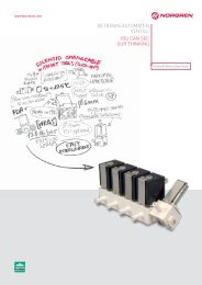
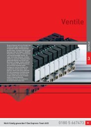
<strong>VALVES</strong><br />
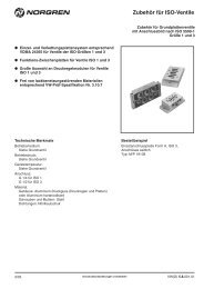
Valve Manifolds VS18 Series<br />
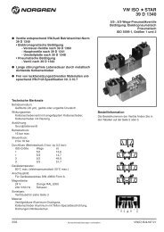
Plug-in Mini ISO Valves<br />
2x2/2, 2x3/2, 5/2 and 5/3 valves, ISO 15407-2, Size 18 mm<br />
Fieldbus protocol: Interbus-S<br />
Connector: 2 x D-Sub 9-pin / M12 4-pin<br />
M12<br />
1.0<br />
(26.5)<br />
M 12 M 12<br />
0.85<br />
(21.5)<br />
VAL-20<br />
2.32 (59)<br />
1.46 (37)<br />
2.32 (59)<br />
0.61<br />
(15.5)<br />
0.83<br />
(21)<br />
5 4 3 2 1<br />
9 8 7 6<br />
1 2 3 4 5<br />
6 7 8 9<br />
0.85<br />
(21.5)<br />
0.87<br />
(22)<br />
0.79<br />
(20)<br />
3<br />
4 2<br />
1<br />
Fieldbus protocol: AS-Interface<br />
Fieldbus protocol: FD67 bus<br />
Connector: 2 x M12 6-pin (power connector integrated<br />
in bus connectors)<br />
M 12<br />
M 12<br />
0.71<br />
(18)<br />
2.32 (59)<br />
0.59<br />
(15)<br />
3<br />
4 2<br />
1<br />
3<br />
4 2<br />
1<br />
0.73<br />
(18.5)<br />
6 789<br />
Male<br />
1<br />
2<br />
3<br />
4<br />
5<br />
4<br />
4<br />
4<br />
1<br />
2<br />
3<br />
4<br />
5<br />
Bus connector: M12 4-pin<br />
Pin no. Function<br />
Max.<br />
current<br />
1 AS-I 3)<br />
2 - -<br />
3 AS-I -<br />
4 - -<br />
Power connector: M12 4-pin<br />
Pin no. Function<br />
Tolerance Max.<br />
current<br />
1 +24 V DC +/-10% 4)<br />
2 - - -<br />
3 0 volts - -<br />
4 - - -<br />
<strong>Norgren</strong>.com/usa – 303.794.2611 – help@amer.norgren.com<br />
Female<br />
Communication in Communication out<br />
Male<br />
1<br />
Male<br />
1<br />
1<br />
6 789<br />
3<br />
2<br />
3<br />
2<br />
Communication<br />
in/out<br />
Male<br />
Male<br />
4<br />
5 3<br />
6<br />
1 2<br />
3<br />
2<br />
Communication<br />
in<br />
Female<br />
4<br />
3 5<br />
6<br />
2 1<br />
Communication<br />
out<br />
Bus connector: D-Sub 9-pin<br />
Pin no. Function Male Function Female<br />
1 DO DO<br />
2 DI DI<br />
3 OVI OVI<br />
4 – –<br />
5 – +5VI<br />
6 /DO /DO<br />
7 /DI /DI<br />
8 – –<br />
9 – RBST<br />
Power connector: M12 4-pin<br />
Pin no. Function Tolerance Max.<br />
current<br />
1 24 VB logic circuit supply +/-25%<br />
300 mA<br />
2 24 VA valves +/-10%<br />
1)<br />
3 0 volts –<br />
2)<br />
4 Earth –<br />
-<br />
Bus connector: M12 6-pin (B-coded)<br />
Pin no. Function Tolerance Max.<br />
current<br />
1 24 V actuator supply ±10% 5)<br />
2 24 V sensor supply/internal supply ±25% 30 mA<br />
3 Ground - -<br />
4 Internal system connection - -<br />
5 Internal system connection - -<br />
6 Ground - -<br />
1) Imax = 10 mA + n*60 mA<br />
n = number of energized solenoids<br />
2) Imax = IVA + IVB 3) Single slave: 40 mA<br />
Double slave: 75 mA<br />
4) Single slave:<br />
Imax = 20 mA + n*60 mA<br />
Double slave:<br />
Imax = 35 mA + n*60 mA<br />
n = number of energized solenoids<br />
5) Imax = n*60 mA<br />
n = number of energized solenoids