VALVES - Norgren Pneumatics. Motion Control Equipment, Fluid ...
VALVES - Norgren Pneumatics. Motion Control Equipment, Fluid ...
VALVES - Norgren Pneumatics. Motion Control Equipment, Fluid ...

Create successful ePaper yourself
Turn your PDF publications into a flip-book with our unique Google optimized e-Paper software.
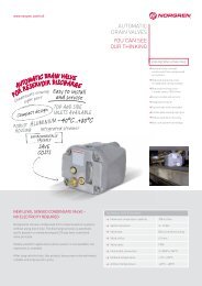
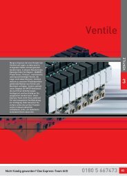
<strong>VALVES</strong><br />
Valve Manifolds VS45 Series<br />
Size 45 mm<br />
Fieldbus options: Overview<br />
Fieldbus protocol Fieldbus Supply voltage connector No. of stations Max. no<br />
interface/connector (Fieldbus and valves) coils<br />
Profibus DP 1 x D-Sub 9-pin M12 4-pin 04/05/06/07/08/09/10/11/12/13/14/15/16 32<br />
2 x M12 5-pin M12 4-pin 04/05/06/07/08/09/10/11/12/13/14/15/16 32<br />
2 x M12 5-pin 7/8 5-pin 04/05/06/07/08/09/10/11/12/13/14/15/16 32<br />
DeviceNet 1 x M12 5-pin M12 4-pin 04/05/06/07/08/09/10/11/12/13/14/15/16 32<br />
CANopen 1 x M12 5-pin M12 4-pin 04/05/06/07/08/09/10/11/12/13/14/15/16 32<br />
For parts and assembly instructions of Fieldbus components, consult our technical service.<br />
Fieldbus protocol: Profibus DP<br />
Connector: 1 x D-Sub 9-pin / M12 4-pin<br />
M 12<br />
0.85 (21.6)<br />
VAL-66<br />
2.78 (70.7)<br />
1.41 (35.8)<br />
Connector: 2 x M12 5-pin / M12 4-pin<br />
M 12<br />
M 12<br />
M 12<br />
M 12<br />
M 12<br />
0.85 (21.6)<br />
3.10 (78.8)<br />
2.26 (57.3)<br />
1.41 (35.8)<br />
Connector: 2 x M12 5-pin / 7/8 5-pin<br />
1.09 (27.7)<br />
1.11 (28.3)<br />
4<br />
3 1<br />
2<br />
12/14<br />
1<br />
5 3<br />
1.09 (27.7)<br />
0.85 (21.6) 0.98 (24.8)<br />
3.14 (79.8)<br />
2.42 (61.3)<br />
1.51 (38.3)<br />
4<br />
3 1<br />
1.39 (35.3)<br />
2<br />
0.96 (24.3)<br />
12/14<br />
1<br />
5 3<br />
12/14<br />
3<br />
5 2<br />
1<br />
5 3<br />
4<br />
4<br />
Male<br />
1<br />
3<br />
5 2<br />
1<br />
3<br />
4<br />
3<br />
1<br />
2<br />
3<br />
4<br />
5<br />
4<br />
4<br />
5 1<br />
Bus connector: D-Sub 9-pin<br />
Pin no. Function<br />
1 Shield<br />
2 N/C<br />
3 B-line (red) RxD / TxD-P<br />
4 N/C<br />
5 DGND (OVI) isolated<br />
6 VP (5VI) isolated<br />
7 N/C<br />
8 A-line (green) RxD / TxD-N<br />
9 N/C<br />
Power connector: M12 4-pin<br />
Pin no. Function Tolerance Max.<br />
current<br />
1 24 VB logic circuit supply +/-25% 300 mA<br />
2 24 VA valves +/-10% 1)<br />
3 0 volts – 2)<br />
4 Earth – –<br />
Bus connector: M12 5-pin (B-coded)<br />
Pin no. Function<br />
1 5VI opto isolated<br />
2 A-line (green)<br />
3 OVI isolated<br />
4 B-line (red)<br />
5 Shield<br />
Threaded joint Shield<br />
Power connector: M12 4-pin<br />
Pin no. Function Tolerance Max<br />
current<br />
1 24 VB logic circuit supply +/-25% 300 mA<br />
2 24 VA valves +/-10% 1)<br />
3 0 volts – 2)<br />
4 Earth – –<br />
Bus connector: M12 5-pin (B-coded)<br />
Pin no. Function<br />
1 5VI isolated<br />
2 A-line (green)<br />
3 OVI isolated<br />
4 B-line (red)<br />
5 Shield<br />
Threaded joint Shield<br />
Power connector: 7/8 5-pin<br />
Pin no. Function Tolerance Max.<br />
current<br />
1 - - -<br />
2 0 volts - 2)<br />
3 Earth - -<br />
4 24 VA valves +/-10% 1)<br />
5 24 VB logic circuit supply +/-25% 300 mA<br />
<strong>Norgren</strong>.com/usa – 303.794.2611 – help@amer.norgren.com<br />
Female<br />
2<br />
1<br />
1<br />
Male<br />
4<br />
5 1<br />
2<br />
6 789<br />
Communication<br />
in/out<br />
Male<br />
Female<br />
3<br />
2<br />
Communication in Communication out<br />
Male<br />
3<br />
2<br />
Male Female<br />
Communication in Communication out<br />
3<br />
4 2<br />
5 1<br />
1) Imax = 10 mA + n*60 mA<br />
n = number of energized solenoids<br />
2) Imax = I VA + I VB