- Page 1 and 2:
RPi Buying Guide From eLinux.org Co
- Page 3 and 4:
Farnell Worldwide Premier Farnell a
- Page 5 and 6:
Q: If interest was obviously so hig
- Page 7 and 8:
limited to batches of only 10k Rasp
- Page 9 and 10:
References 1. ↑ http://en.wikiped
- Page 11 and 12:
SD Card setup To boot the Raspberry
- Page 13 and 14:
Copying the image to an SD Card on
- Page 15 and 16:
1. These commands and actions need
- Page 17 and 18:
▪ dd bs=4M if=~/2012-09-18-wheezy
- Page 19 and 20:
Model: SD SD08G (sd/mmc) Disk /dev/
- Page 21 and 22:
RPi Hardware Basic Setup From eLinu
- Page 23 and 24:
NOTE: An RPi SD card can only be us
- Page 25 and 26:
1. Micro-B USB Power Cable (see abo
- Page 27 and 28:
One promising device is the Cymbet
- Page 29 and 30:
External Links For a verbose guide
- Page 31 and 32:
This page is a community work in pr
- Page 33 and 34:
===================================
- Page 35 and 36:
NOTE: If the partitions (/dev/sdc1
- Page 37 and 38:
Setting up for remote access / head
- Page 39 and 40:
continue to be able to address it i
- Page 41 and 42:
An alternative startup guide for be
- Page 43 and 44:
Where to start? Any easy question t
- Page 45 and 46:
If you're unsure of which locale to
- Page 47 and 48:
Debian Wheezy, using raspi-config D
- Page 49 and 50:
Media Player With this configuratio
- Page 51 and 52:
▪ Entering "sudo apt-get install
- Page 53 and 54:
Tutorials - Guides - Projects - Tas
- Page 55 and 56:
▪ 5.5 Networking no longer works
- Page 57 and 58:
Green LED blinks in a specific patt
- Page 59 and 60:
can only handle 100mA per USB slot
- Page 61 and 62:
Get the latest firmware version The
- Page 63 and 64:
Ethernet connects at 10M instead of
- Page 65 and 66:
Some programs refuse to accept my p
- Page 67 and 68: Display Startx fails to start If yo
- Page 69 and 70: overscan_bottom=20 Interference vis
- Page 71 and 72: Composite displays no image The out
- Page 73 and 74: Troubleshooting power problems If y
- Page 75 and 76: Hardware versions/revisions Several
- Page 77 and 78: Raspberry Pi Model Wizard - Buying
- Page 79 and 80: # Set monitor mode to DMT hdmi_grou
- Page 81 and 82: hdmi_drive=1 Normal DVI mode (No so
- Page 83 and 84: hdmi_mode=46 1440x900 reduced blank
- Page 85 and 86: opt/vc/bin/tvservice -d edid.dat /o
- Page 87 and 88: Overclocking options Option Descrip
- Page 89 and 90: GPU core, h264, v3d and isp should
- Page 91 and 92: RPi Hardware From eLinux.org Conten
- Page 93 and 94: Low-level peripherals: Real-time cl
- Page 95 and 96: core clocked at 700MHz; ARM VFP. Th
- Page 97 and 98: Power ▪ High-resolution PCB front
- Page 99 and 100: the RPI itself, sometimes up to hal
- Page 101 and 102: Things that can cause problems ▪
- Page 103 and 104: Capacitor C6 (ringed) It's unlikely
- Page 105 and 106: RPi HardwareHistory From eLinux.org
- Page 107 and 108: Raspberry Pi Model-B Full Productio
- Page 109 and 110: Raspberry Pi Alpha Board ▪ Announ
- Page 111 and 112: 10. ↑ (hand-mod) More on the beta
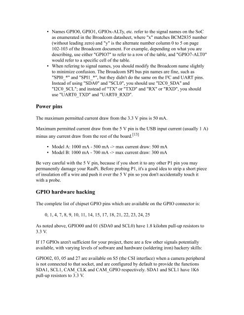
- Page 113 and 114: Introduction In addition to the fam
- Page 115 and 116: Each GPIO can interrupt, high/low/r
- Page 117: Colour legend +5 V +3.3 V Ground, 0
- Page 121 and 122: GPIO Code examples GPIO Driving Exa
- Page 123 and 124: ); BLOCK_SIZE, PROT_READ|PROT_WRITE
- Page 125 and 126: # Set up GPIO 7 and set to input ec
- Page 127 and 128: gcc -o blink -I ../../src ../../src
- Page 129 and 130: GPIO Driving Example (Ruby) This ex
- Page 131 and 132: Model Wizard - Buying Guide - SD Ca
- Page 133 and 134: Back to the Hub. Contents ▪ 1 Int
- Page 135 and 136: AFLEX Robotic Board AFLEX Robotic B
- Page 137 and 138: Pi232 RS232 board Pi232 (http://www
- Page 139 and 140: MiniPiio Relay2 [7] (http://zuzebox
- Page 141 and 142: line in it for commands. The interf
- Page 143 and 144: RPi Screens From eLinux.org Back to
- Page 145 and 146: http://www.hdfury.com/ Something si
- Page 147 and 148: Nokia N8 has AMOLED 360x640 pixels
- Page 149 and 150: RPi Cases From eLinux.org Back to R
- Page 151 and 152: Back to the Hub. ▪ 32.5 Customiza
- Page 153 and 154: Lego Case 2 I had a bit of a play i
- Page 155 and 156: This unique case has an integrated
- Page 157 and 158: The foldable case from "Andrew K" (
- Page 159 and 160: Both bottom and top of the case are
- Page 161 and 162: ModMyPi - Raspberry Topping Case Mo
- Page 163 and 164: RepRap friendly cover for Raspberry
- Page 165 and 166: Design One (http://www.thingiverse.
- Page 167 and 168: FoamBox1.png FoamBox2.png FoamBox3.
- Page 169 and 170:
PI Sandwich Case BUD Industries is
- Page 171 and 172:
▪ Customizable! ▪ Nearly Indest
- Page 173 and 174:
The PiSlab is made from a slab of 1
- Page 175 and 176:
Options 4 Different Design Access t
- Page 177 and 178:
Polycase Pi Series Case The new Pi
- Page 179 and 180:
Tek Berry.40 Length: 100.6 Width: 7
- Page 181 and 182:
Raspberry Pi Model Wizard - Buying
- Page 183 and 184:
Back to the Hub. Contents ▪ 1 Not
- Page 185 and 186:
▪ (B) - Relates to model B produc
- Page 187 and 188:
▪ F5U706ea/uk 2-in-1 Hub (USB 2.0
- Page 189 and 190:
▪ Logik L4THUB10 4 Port powered h
- Page 191 and 192:
Problem USB Hubs Please check known
- Page 193 and 194:
thing is that RPi powers on when I
- Page 195 and 196:
▪ A4 Tech ▪ Model KL-5 USB Keyb
- Page 197 and 198:
▪ EBO-013 Wireless 2.4GHz compact
- Page 199 and 200:
▪ Comfort Wave 450, labeled 100mA
- Page 201 and 202:
▪ ONN Keyboard Stock No: ONA11HO0
- Page 203 and 204:
▪ Trust 17916 Compact Wireless En
- Page 205 and 206:
▪ G510 Gaming Keyboard - lagging
- Page 207 and 208:
▪ DX-WMSE (100mA) (B) ▪ Fellowe
- Page 209 and 210:
▪ Samsung model:AA-SM3PCPB usb Op
- Page 211 and 212:
USB WiFi Adapters See also: http://
- Page 213 and 214:
▪ Belkin Components F7D1101 v1 Ba
- Page 215 and 216:
▪ Edimax ▪ EW-7811Un (http://ww
- Page 217 and 218:
▪ MSI ▪ Micronet SP907NS, 11N W
- Page 219 and 220:
▪ SMC ▪ SMCWUSBS-N : Hardware d
- Page 221 and 222:
Wheezy) as it includes the needed 8
- Page 223 and 224:
▪ Apple ▪ Apple USB Ethernet Ad
- Page 225 and 226:
Tested on Raspbian and Archlinux. D
- Page 227 and 228:
▪ Webcam C100 Model Number V-U001
- Page 229 and 230:
correctly on boot. You may need to
- Page 231 and 232:
USB RFID Reader JTAG ▪ Unbranded
- Page 233 and 234:
▪ Universal USB Wall Charger (5V
- Page 235 and 236:
▪ RS Components' ▪ HNP06UK (RS
- Page 237 and 238:
Display adapters Note that active c
- Page 239 and 240:
hdmi_mode=36 disable_overscan=1 Acc
- Page 241 and 242:
Working SD Cards ▪ 4GB SDHC Class
- Page 243 and 244:
▪ 8GB SDHC Class 4 (doesn't reboo
- Page 245 and 246:
▪ Mushkin ▪ 16GB SDHC Class 10
- Page 247 and 248:
▪ 32GB SDHC Class 10 (MB-SSBGA, M
- Page 249 and 250:
(http://www.amazon.co.uk/gp/product
- Page 251 and 252:
▪ 32GB SDHC Class 10 (http://www.
- Page 253 and 254:
▪ 4GB SDHC Class 4 — hasn't wor
- Page 255 and 256:
(http://www.raspberrypi.org/phpBB3/
- Page 257 and 258:
Model Wizard - Buying Guide - SD Ca
- Page 259 and 260:
We're not currently using a bootloa
- Page 261 and 262:
Performance Performance Page Progra
- Page 263 and 264:
Back to the Hub. Software & Distrib
- Page 265 and 266:
Fedora Remix (http://fedoraproject.
- Page 267 and 268:
Wiki & Main site (http://androidpi.
- Page 269 and 270:
The generally small system that pro
- Page 271 and 272:
ha-pi ▪ Main Site (https://source
- Page 273 and 274:
FreeBSD Details and install guide o
- Page 275 and 276:
GeeXboX ARM GeeXboX is a free and O
- Page 277 and 278:
RPi Kernel Compilation From eLinux.
- Page 279 and 280:
From a foreign machine Firmware cd
- Page 281 and 282:
From opensource.apple.com, download
- Page 283 and 284:
Tutorials - Guides - Projects - Tas
- Page 285 and 286:
CPU Linpack The Arm has been tested
- Page 287 and 288:
Reps Time(s) DGEFA DGESL OVERHEAD K
- Page 289 and 290:
cast cbc 5068.25k 6020.03k 6345.71k
- Page 291 and 292:
armhf "driver info" : http://i.imgu
- Page 293 and 294:
Extrememory SDHC 16GB class 10 (man
- Page 295 and 296:
Patriot SDHC 32GB Class 10 UHS-1 (P
- Page 297 and 298:
SanDisk SDHC 32GB class 6 SanDisk u
- Page 299 and 300:
Sandisk Ultra SDHC I Class 6 ("30MB
- Page 301 and 302:
65.1 + 48.8 69.5 + 29.1 90.8 + 91.4
- Page 303 and 304:
RPi Programming From eLinux.org Bac
- Page 305 and 306:
Graphical Programming ▪ Gambas (h
- Page 307 and 308:
Tutorials - Guides - Projects - Tas
- Page 309 and 310:
Kernel Compilation - advice on comp
- Page 311 and 312:
ilclient helper library This librar
- Page 313 and 314:
egistry/egl/specs/eglspec.1.4.20110
- Page 315 and 316:
specs/openvg-1.1.pdf) or the API qu
- Page 317 and 318:
RPi Tutorials From eLinux.org
- Page 319 and 320:
Community Pages: Tutorials - a list
- Page 321 and 322:
DracoSoftware (http://dracosoftware
- Page 323 and 324:
5V Power Supply construction - How
- Page 325 and 326:
Live mp3 streaming from audio-in wi
- Page 327 and 328:
RPi Guides From eLinux.org Back to
- Page 329 and 330:
web browser Easy Suitable for begin
- Page 331 and 332:
Installing Ruby on Rails Share your
- Page 333 and 334:
Using Skypekit Pre-configuring SD c
- Page 335 and 336:
RPi Projects From eLinux.org Back t
- Page 337 and 338:
BerryTerminal (http://www.berryterm
- Page 339 and 340:
Digital Signage Retrieved from "htt
- Page 341 and 342:
The Raspberry Pi Foundation is a UK
- Page 343 and 344:
5. Optional USB driver for 2-device
- Page 345 and 346:
R-Pi System/Data Management --Meltw
- Page 347 and 348:
Model Wizard - Buying Guide - SD Ca
- Page 349 and 350:
101-200 Raspberry Pi Foundation ann
- Page 351 and 352:
RPi Education From eLinux.org Conte
- Page 353 and 354:
Computer History Museum, Silicon Va
- Page 355 and 356:
used for Desktop apps, Daemon/Servi
- Page 357 and 358:
fundamentals of computer programmin
- Page 359 and 360:
▪ https://github.com/ntoll/Raspbe
- Page 361 and 362:
RPi Community From eLinux.org Back
- Page 363 and 364:
▪ RasPi Forums on EduGeek.net (ht
- Page 365:
References 1. ↑ http://www.pyroso