Download - ADInstruments
Download - ADInstruments
Download - ADInstruments

You also want an ePaper? Increase the reach of your titles
YUMPU automatically turns print PDFs into web optimized ePapers that Google loves.
The Status Indicator<br />
The Status indicator light is located at the bottom right of the front<br />
panel. When an <strong>ADInstruments</strong> program such as LabChart starts up,<br />
the Status indicator should flash briefly and then remain green,<br />
indicating that the program has found the front-end, checked and<br />
selected it, and is ready to use it. If a Status indicator does not turn on<br />
and stay on when the program is run, this indicates either that the<br />
front-end is not connected properly or that there is a software or<br />
hardware problem.<br />
The GP Amp Input Socket<br />
Transducers are connected to a GP Amp using the eight-pin DIN<br />
socket on the front panel. The connector provides terminals for<br />
supplying a transducer with power and for measuring the transducer<br />
output. The GP Amp is supplied with a DIN plug kit that can be fitted<br />
to a transducer that lacks a DIN connection. The connection is<br />
discussed in more detail later.<br />
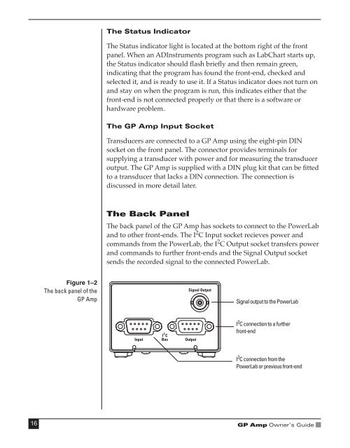
The Back Panel<br />
The back panel of the GP Amp has sockets to connect to the PowerLab<br />
and to other front-ends. The I 2 C Input socket recieves power and<br />
commands from the PowerLab, the I 2 C Output socket transfers power<br />
and commands to further front-ends and the Signal Output socket<br />
sends the recorded signal to the connected PowerLab.<br />
Figure 1–2<br />
The back panel of the<br />
GP Amp<br />
Signal output to the PowerLab<br />
I 2 C connection to a further<br />
front-end<br />
I 2 C connection from the<br />
PowerLab or previous front-end<br />
16<br />
GP Amp Owner’s Guide