Download - ADInstruments
Download - ADInstruments
Download - ADInstruments

You also want an ePaper? Increase the reach of your titles
YUMPU automatically turns print PDFs into web optimized ePapers that Google loves.
Power rating<br />
0.25 Watt<br />
Temperature coefficient Better than 10 ppm per °C<br />
Matched temperature coefficient 1 ppm per °C<br />
Resistor matching Better than 0.05%<br />
Resistor tolerance<br />
1% or better<br />
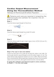
Solder the resistors as shown in Figure 3–6. Notice that the top ends of<br />
the resistors are joined together and then soldered to pin 2.<br />
Figure 3–6<br />
Installing the compensating<br />
resistors (the programming<br />
resistor has been left out<br />
for clarity)<br />
Pin 2<br />
Pin 4<br />
Half-bridge<br />
compensating<br />
resistors<br />
Pin 1<br />
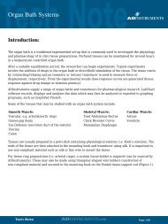
Once the resistors have been soldered into the correct places, connect<br />
the transducer wiring to the DIN plug as shown in Figure 3–7. The<br />
transducer will normally have some sort of cable shield, which should<br />
be connected to pin 7 of the DIN plug. If the casing of the DIN plug is<br />
metal, it is good practice to ensure that it will also be connected to the<br />
shield. This is not necessary, but is recommended.<br />
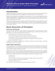
Figure 3–7<br />
The wiring connections for<br />
a half-bridge transducer,<br />
looking at the DIN plug<br />
from the rear<br />
Ground or center tap (shield)<br />
Signal positive (+)<br />
Excitation negative (–)<br />
Excitation positive (+)<br />
5<br />
2<br />
4<br />
3<br />
1<br />
8<br />
6 7<br />
Excitation<br />
voltage<br />
programming<br />
resistor<br />
Half-bridge<br />
compensating<br />
resistors<br />
38<br />
GP Amp Owner’s Guide