Download - ADInstruments
Download - ADInstruments
Download - ADInstruments

Create successful ePaper yourself
Turn your PDF publications into a flip-book with our unique Google optimized e-Paper software.
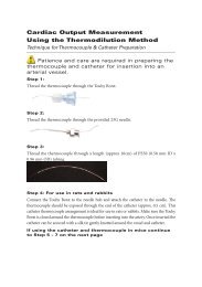
GP Amp Operation<br />
The GP Amp is essentially an extension of the PowerLab’s analog<br />
input. The GP Amp provides:<br />
• a ±10 V DC excitation source that can power transducers requiring<br />
such excitation<br />
• the additional amplification necessary to deal with the low signal<br />
outputs of most transducers<br />
• high-impedance differential input<br />
• additional programmable filtering to remove unwanted signal<br />
frequencies<br />
• digitally controlled zeroing circuitry for offset removal.<br />
The internal functions of the GP Amp are controlled from the<br />
PowerLab through the I 2 C bus, which also supplies power to the<br />
GP Amp. The front-end sends the signal to an analog input channel of<br />
the PowerLab via a BNC-to-BNC cable. The overall operation of the<br />
GP Amp can be better understood by referring to Figure A–1.<br />
Figure A–1<br />
Block diagram of the<br />
GP Amp<br />
AC/DC<br />
coupling<br />
Gain<br />
control<br />
Filter<br />
control<br />
Signal<br />
input<br />
+<br />
_<br />
×1 /<br />
× 10/<br />
× 100<br />
10 kHz<br />
100 Hz<br />
10 Hz<br />
Signal analog<br />
Output output<br />
Transducer<br />
power<br />
Excitation<br />
voltage adjust<br />
On-line<br />
indicator<br />
Excitation<br />
driver<br />
DC offset<br />
control<br />
VRef<br />
12-bit<br />
DAC<br />
1 Hz<br />
2 2<br />
I C<br />
control<br />
interface<br />
+<br />
power<br />
supply<br />
I 2 C I C<br />
output Output<br />
2<br />
I 2 C I C<br />
Input input<br />
The input stage is a high-impedance differential instrumentation<br />
amplifier. The amplifier provides additional signal amplification.<br />
42<br />
GP Amp Owner’s Guide