An Integrated Circuit With Transmit Beamforming Flip ... - IEEE Xplore
An Integrated Circuit With Transmit Beamforming Flip ... - IEEE Xplore
An Integrated Circuit With Transmit Beamforming Flip ... - IEEE Xplore

Create successful ePaper yourself
Turn your PDF publications into a flip-book with our unique Google optimized e-Paper software.
<strong>IEEE</strong> Transactions on Ultrasonics, Ferroelectrics, and Frequency Control, vol. 56, no. 10, October 2009<br />
<strong>An</strong> <strong>Integrated</strong> <strong>Circuit</strong> <strong>With</strong> <strong>Transmit</strong><br />
<strong>Beamforming</strong> <strong>Flip</strong>-Chip Bonded to a 2-D<br />
CMUT Array for 3-D Ultrasound Imaging<br />
Ira O. Wygant, Student Member, <strong>IEEE</strong>, Nafis S. Jamal, Student Member, <strong>IEEE</strong>,<br />
Hyunjoo J. Lee, Student Member, <strong>IEEE</strong>, Amin Nikoozadeh, Student Member, <strong>IEEE</strong>,<br />
Ömer Oralkan, Member, <strong>IEEE</strong>, Mustafa Karaman, Member, <strong>IEEE</strong>,<br />
and Butrus T. Khuri-Yakub, Fellow, <strong>IEEE</strong><br />
Abstract—State-of-the-art 3-D medical ultrasound imaging<br />
requires transmitting and receiving ultrasound using a 2-D<br />
array of ultrasound transducers with hundreds or thousands<br />
of elements. A tight combination of the transducer array with<br />
integrated circuitry eliminates bulky cables connecting the elements<br />
of the transducer array to a separate system of electronics.<br />
Furthermore, preamplifiers located close to the array<br />
can lead to improved receive sensitivity. A combined IC and<br />
transducer array can lead to a portable, high-performance, and<br />
inexpensive 3-D ultrasound imaging system. This paper presents<br />
an IC flip-chip bonded to a 16 × 16-element capacitive<br />
micromachined ultrasonic transducer (CMUT) array for 3-D<br />
ultrasound imaging. The IC includes a transmit beamformer<br />
that generates 25-V unipolar pulses with programmable focusing<br />
delays to 224 of the 256 transducer elements. One-shot<br />
circuits allow adjustment of the pulse widths for different ultrasound<br />
transducer center frequencies. For receiving reflected<br />
ultrasound signals, the IC uses the 32-elements along the array<br />
diagonals. The IC provides each receiving element with a<br />
low-noise 25-MHz-bandwidth transimpedance amplifier. Using<br />
a field-programmable gate array (FPGA) clocked at 100 MHz<br />
to operate the IC, the IC generated properly timed transmit<br />
pulses with 5-ns accuracy. <strong>With</strong> the IC flip-chip bonded to a<br />
CMUT array, we show that the IC can produce steered and<br />
focused ultrasound beams. We present 2-D and 3-D images of<br />
a wire phantom and 2-D orthogonal cross-sectional images (Bscans)<br />
of a latex heart phantom.<br />
I. Introduction<br />
Real-time 3-D ultrasound imaging is an increasingly<br />
prevalent medical imaging technology in fields such<br />
as obstetrics [1], [2] and cardiology [3], [4]. In contrast to<br />
traditional 2-D ultrasound imaging systems, 3-D imaging<br />
systems can form 2-D image planes in any orientation<br />
relative to the ultrasound transducer array and can acquire<br />
volumetric images. These capabilities simplify image<br />
acquisition and aid making quantitative measurements<br />
Manuscript received October 16, 2008; accepted June 30, 2009. This<br />
work was supported by NIH grant CA99059. Work was performed in<br />
part at the Stanford Nanofabrication Facility (a member of the National<br />
Nanotechnology Infrastructure Network) which is supported by the National<br />
Science Foundation under Grant ECS-9731293.<br />
I. O. Wygant, N. S. Jamal, H. J. Lee, A. Nikoozadeh, Ö. Oralkan, and<br />
B. T. Khuri-Yakub are with the Edward L. Ginzton Laboratory, Stanford<br />
University, Stanford, CA (e-mail: iwygant@stanford.edu).<br />
M. Karaman is with the Electronics Engineering Department, Işik<br />
University, Istanbul, Turkey.<br />
Digital Object Identifier 10.1109/TUFFC.2009.1297<br />
2145<br />
based on the acquired images [3]. Furthermore, because<br />
3-D images can be acquired quickly and analyzed offline,<br />
examinations with 3-D ultrasound take less time and are<br />
less dependent on the skill of the sonographer [2], [5].<br />
A. Background<br />
Early 3-D ultrasound imaging systems (e.g., [6]) used<br />
sparsely populated 2-D arrays or mechanically scanned<br />
1-D arrays of ultrasound transducer elements to simplify<br />
the transmit and receive electronics. Modern systems, however,<br />
use fully populated 2-D arrays for better image quality.<br />
In general, arrays with more elements result in better<br />
image resolution, contrast, and SNR; commercial systems<br />
use arrays with thousands of elements [7]. The elements<br />
in the arrays are typically about one-half wavelength in<br />
length and width (150 μm at 5 MHz). Connecting to and<br />
processing the signals from the elements of a large 2-D array<br />
require sophisticated packaging and electronics.<br />
System connection cables are too bulky for connecting<br />
each element of a hand-held transducer array to a separate<br />
system of electronics. Furthermore, the capacitance<br />
of long cables (commonly 100 pF/m [8]) degrades the receive<br />
sensitivity of 2-D transducer array elements, which<br />
have capacitance on the order of several picofarads.<br />
Incorporating some of the system’s electronics into the<br />
hand-held probe results in fewer cables and better receive<br />
sensitivity. Furthermore, a compact connection between<br />
the array and integrated circuitry can result in a highly<br />
portable and inexpensive 3-D ultrasound imaging system.<br />
Such a system would enable wider use of 3-D ultrasound<br />
imaging, particularly because portability and cost, along<br />
with real-time imaging, are key advantages of ultrasound<br />
imaging compared with other common medical imaging<br />
modalities such as magnetic resonance imaging (MRI) and<br />
computed tomography (CT).<br />
The electronics of a phased array 3-D ultrasound imaging<br />
system use the transducer array to steer a focused<br />
beam of ultrasound over the volume being imaged, and to<br />
detect the resulting reflected ultrasound. To generate a focused<br />
beam of ultrasound, a transmit beamformer provides<br />
each transmitting array element with a high-voltage pulse,<br />
or a series of coded pulses. The pulses are delayed relative<br />
to each other to create a beam of ultrasound steered in<br />
the direction of a focal point. A transmit beamformer that<br />
0885–3010/$25.00 © 2009 <strong>IEEE</strong>
2146 <strong>IEEE</strong> Transactions on Ultrasonics, Ferroelectrics, and Frequency Control, vol. 56, no. 10, October 2009<br />
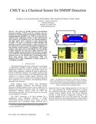
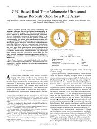
Fig. 1. Top-level diagram of the IC. The IC is designed to be flip-chip<br />
bonded to a 16 × 16-element ultrasound transducer array. It provides a<br />
25-V pulser circuit to each of the 224 transmitting elements and a lownoise<br />
preamplifier to each of the 32 receiving elements. A control signal<br />
enables 16 receivers at a time for output on 16 signal lines.<br />
accommodates high-voltage pulses (ideally 100 V or more<br />
[9]) and uses more elements of the transducer array results<br />
in better image SNR, with the limitation that peak ultrasound<br />
pressures and average ultrasound intensities cannot<br />
surpass government-mandated limits [10]–[12]. The<br />
accuracy of the transmit beamformer’s delays impacts the<br />
sidelobe levels of the transmitted beams [13], [14]. Simulations<br />
of a specific imaging system’s image of a point<br />
reflector [15], referred to as the point spread function, give<br />
precise indications of how delay quantization and delay<br />
uncertainty impact image quality.<br />
The receiving electronics of a 3-D imaging system include<br />
preamplifiers, time-gain-compensation (TGC) amplifiers,<br />
and a receive beamformer. The preamplifiers should<br />
amplify the transducer signal while adding as little noise<br />
as possible to the input-referred noise of the transducer<br />
[16]. For 2-D array elements, which have a high impedance,<br />
the preamplifiers should be closely located to the array<br />
elements. TGC amplifiers equalize the echoes received<br />
from objects at different distances from the transducer by<br />
providing gain that increases with time for each received<br />
signal. A receive beamformer delays and coherently adds<br />
the received signals from different array elements to create<br />
a focused beam. To increase the frame rate for 3-D<br />
imaging, the transmitted beams may be defocused to create<br />
wider beams, in which case the receive beamformer<br />
creates several focused beams per transmitted beam [17],<br />
[18]. <strong>An</strong>alog-to-digital converters (ADCs) convert the focused<br />
beams to digital signals for further processing and<br />
display. In systems with relatively few receiving elements<br />
(e.g., 2-D imaging systems) the detected echoes can be<br />
converted to digital signals before receive beamforming.<br />
However, for large 2-D arrays, providing ADCs to every<br />
element is not practical.<br />
Because 2-D transducer array elements are tightly<br />
packed together, electronics must connect to the array<br />
elements from the back side. Frequently this connection<br />
requires a specially designed connector to join pads on<br />
the back side of the transducer array with the pads of a<br />
flexible circuit board or an integrated circuit [19]–[25]. Alternatively,<br />
micromachined or polymer-based transducer<br />
technologies allow for the direct fabrication of the transducer<br />
array on an integrated circuit [26]–[30]. However,<br />
these methods generally require compromises in transducer<br />
fabrication methods. We directly flip-chip bond micromachined<br />
transducer arrays with through-wafer interconnects<br />
to an IC [31].<br />
The literature contains numerous integrated circuit<br />
designs for ultrasound imaging systems. These studies<br />
include transmit beamformers [32], [33], analog receive<br />
beamformers [34]–[38], ADCs [39], and complete imaging<br />
systems [40]. High-voltage switch arrays for multiplexing<br />
have also been studied for multiplexing numerous transducer<br />
array elements over a fixed number of transmit and<br />
receive electronic channels [29], [41], [42].<br />
In [31], we have described an IC flip-chip bonded to a<br />
2-D transducer array for 3-D imaging. <strong>With</strong> that device,<br />
we demonstrated 100% element yield, good receive sensitivity,<br />
and a reliable means of flip-chip bonding a 2-D<br />
capacitive micromachined ultrasonic transducer (CMUT)<br />
array with through-wafer interconnects to an IC. The IC<br />
presented in [31] provided a pulser and preamplifier to<br />
every transducer element but only a single element could<br />
be used at a time for transmit and receive. As a result,<br />
we used classic synthetic aperture imaging, which suffers<br />
from lower SNR, higher grating lobes, and motion artifacts<br />
compared with conventional phased array imaging.<br />
B. Device Overview<br />
In this paper, we present the design and testing of an<br />
IC that uses a 16 × 16-element transducer array for 3-D
wygant et al.: ic and transducer for 3-d ultrasound imaging<br />
2147<br />
TABLE I. IC Design Properties.<br />
Parameter Single-Channel [31] 16-Channel<br />
Array size 16 × 16 16 × 16<br />
<strong>Transmit</strong> elements 256 224<br />
Receive elements 256 32<br />
Pulse voltage 25 V 25 V<br />
Amplifier transimpedance gain 430 kΩ 215 kΩ<br />
Amplifier bandwidth 10 MHz 25 MHz<br />
Simultaneous active transmit elements 1 224<br />
Simultaneous active receive elements 1 16<br />
Power per receive channel 9 mW 9 mW<br />
ultrasound imaging. We designed the IC for an intracavital<br />
ultrasound imaging application. However, the design<br />
could be extended to use larger arrays for other ultrasound<br />
imaging applications. The IC comprises a 224-element<br />
transmit beamformer and 32 preamplifiers. The transmit<br />
beamformer provides each of 224 of the 256 transducer elements<br />
with a 25-V pulser, a one-shot circuit, and an 8-bit<br />
shift register. A field-programmable gate array (FPGA)<br />
loads new focusing delay values into the shift registers<br />
for each new transmit beam focus. For receiving, the IC<br />
provides a transimpedance preamplifier to each of the 32<br />
elements along the array diagonals. A previous study [43]<br />
showed that using the array diagonals for receiving gives<br />
acceptable imaging performance with a reduced number<br />
of receive channels. Dividing the array into transmit-only<br />
and receive-only elements simplifies the receive circuitry<br />
by eliminating the need for protection circuitry.<br />
<strong>With</strong> this IC, we demonstrate the integration of the<br />
transmitting electronics, receiving electronics, and transducer<br />
array into a compact device. Compared with previously<br />
reported transmit beamformers [32], [33], the transmit<br />
beamformer presented here provides a much larger<br />
number of pulsers; these pulsers have a relatively high<br />
voltage and are compact enough to be used in arrays with<br />
thousands of elements. Fully packaged intracavital or endoscopic<br />
imaging probes have been demonstrated (e.g.,<br />
[44]); these demonstrations include probes with 2-D transducer<br />
arrays for 3-D imaging [45], [46]. In [44], a customdesigned<br />
IC is closely associated with the transducer array.<br />
Here we show an IC for 3-D imaging that comprises more<br />
of the imaging system’s functionality. Compared with the<br />
IC we describe in [31], the IC described in this paper uses<br />
many more elements in parallel for any single transmit<br />
and receive event, which results in significantly improved<br />
SNR and contrast. Table I compares the key features of<br />
the 2 ICs.<br />
In this paper and in [31] we use CMUT arrays. CMUTs<br />
are ultrasound transducers manufactured using MEMS<br />
technology. They compete with piezolectric transducer<br />
technology for medical imaging [47], [48]. At present,<br />
medical imaging is dominated by piezoelectric transducer<br />
technology; the advantages of piezoelectric transducers<br />
include good transmit sensitivity (Pa/V) and a<br />
well-established manufacturing process. CMUTs provide<br />
wide bandwidth, which translates to better axial resolution,<br />
and benefit from MEMS fabrication processes that<br />
provide design flexibility, tight control over dimensions,<br />
and batch fabrication. For ring-shaped arrays or high-frequency<br />
arrays, the manufacturing advantages of CMUTs<br />
are particularly important [49], [50]. The capability of<br />
incorporating through-wafer interconnects [51], [52] with<br />
the CMUT array allows the array to be directly flip-chip<br />
bonded to the IC.<br />
II. <strong>Circuit</strong> Design and Implementation<br />
We designed the IC for a high-voltage process (National<br />
Semiconductor, Santa Clara, CA) that provides bipolar,<br />
double diffused MOS (DMOS), and low- and high-voltage<br />
CMOS devices. The process provides a single poly layer<br />
and 2 metal layers. We chose this process because it provides<br />
high-voltage CMOS devices for the pulser circuitry.<br />
The process has a relatively large minimum feature size of<br />
1.5 μm, which means that standard implementations of<br />
some circuits occupy large areas. As a result, circuit size<br />
was an important design consideration.<br />
The IC interfaces 224 of the array elements for transmitting;<br />
it interfaces with the remaining 32 elements along<br />
the array diagonals for receiving (Fig. 1). It thus provides<br />
each element of the array with either a transmit circuit<br />
or a preamplifier. The transmit pulser circuit uses a 25-V<br />
supply. The remaining circuitry uses a 5-V supply.<br />
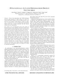
The transmit circuit consists of an 8-bit shift register,<br />
a comparator, a one-shot, and a 25-V pulser (Fig. 2). For<br />
each new transmit beam, the FPGA-based imaging system<br />
that operates the IC loads 8-bit focusing delay values<br />
into every shift register. To transmit the beam, the imaging<br />
system increments an 8-bit Gray-code counter from<br />
one to the number of unique firing times. If, for example,<br />
every element has a unique firing time, then the counter<br />
increments from 1 to 224. Each transmit circuit’s pulser<br />
fires when the value stored in its shift register is equal to<br />
the Gray-code counter. <strong>With</strong> this method of triggering the<br />
pulsers, which is similar to the method described in [32],<br />
the IC can transmit single pulses of arbitrarily steered and<br />
focused ultrasound.<br />
The shift registers [Fig. 3(a)] for each row of 14 transducer<br />
elements connect in series. Sixteen input signals<br />
from the imaging system load the 16 rows of shift registers<br />
in parallel. Because the shift registers are loaded before<br />
each new transmit beam, their load time potentially re-
2148 <strong>IEEE</strong> Transactions on Ultrasonics, Ferroelectrics, and Frequency Control, vol. 56, no. 10, October 2009<br />
Fig. 2. Block diagram of the transmit circuit. Each transmit circuit generates a 25-V pulse when the value stored in its 8-bit shift register is equal to<br />
a global counter. For each new focal point, field-programmable gate array loads new delay values into the shift registers and increments a Gray-code<br />
counter from 0 to the number of unique pulser firing times.<br />
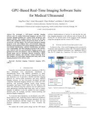
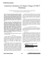
Fig. 3. Key transmit and receive circuits. Low transistor-count circuitry saves die area. (a) The shift register. A transmission-gate register stores<br />
transmit delay information. (b) The comparator. Dynamic logic saves die area and enables a simple one-shot implementation. (c) The one-shot<br />
circuit. A reference current determines the transmit pulse width.<br />
TABLE II. Equivalent <strong>Circuit</strong> Component Values.<br />
Parameter Unit Definition Value<br />
P Pa Impinging ultrasound pressure<br />
A m 2 Equivalent parallel-plate area 9.1 × 10 −9<br />
R rad Rayl∙m 2 Radiation resistance 5.0 × 10 −3<br />
L rad kg Radiation inductance 1.8 × 10 −11<br />
L m kg Equivalent mass 1.2 × 10 −11<br />
1/C m N/m Equivalent spring constant 7.4 × 10 4<br />
n N/V Transformer ratio 8.8 × 10 −5<br />
C 0 pF Device capacitance 0.3<br />
C p pF Estimated parasitic capacitance 0.5<br />
duces the imaging frame rate; thus, their load time should<br />
be small compared with the pulse-echo time of the ultrasound<br />
beam. We assume an imaging depth of more than<br />
3 cm, which corresponds to a pulse-echo time of more than<br />
40 μs. We designed the registers for a load rate greater<br />
than 100 MHz. At 100 MHz, the load time for all 224 shift<br />
registers is 1.1 μs, which is negligible compared with the<br />
pulse-echo time.<br />
In each transmit circuit, when the value stored in the<br />
shift register equals the Gray-code counter provided by<br />
the imaging system, the comparator’s output goes high.<br />
The comparator [Fig. 3(b)] uses dynamic logic that is reset<br />
before each beam transmission. Dynamic logic helps<br />
make the comparator’s size small. Additionally, because<br />
the output of the comparator stays high until the dynamic<br />
logic is reset, we can use a simple XOR implementation<br />
of the one-shot.<br />
The one-shot drives the pulser and thus dictates the<br />
length of the pulse applied to the transducer element.<br />
The one-shot’s output goes low for a time proportional to<br />
C 1 /i set . The current i set is an adjustable current referenced<br />
with current mirrors to an off-chip current source. Every<br />
one-shot has the same i set . Adjusting i set allows the pulse<br />
length to be adjusted for a particular transducer’s frequency<br />
response—transducers operating at higher frequencies<br />
require shorter pulses. In simulation, for i set between 2
wygant et al.: ic and transducer for 3-d ultrasound imaging<br />
2149<br />
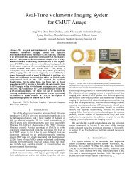
Fig. 4. <strong>An</strong> equivalent circuit model represents the transducer elements<br />
for the preamplifier design. Except for C p , R load , and the radiation impedance,<br />
the circuit components scale with the transducer element size.<br />
As the element size increases relative to a wavelength, the radiation impedance<br />
approaches R med ∙ A, where R med equals 1.5 MRayls for water.<br />
(a) The complete circuit model. (b) At the transducer’s center frequency<br />
in immersion, R rad dominates L rad , R loss , L m , and C m . Thus, the equivalent<br />
circuit simplifies to a current source in parallel with a resistor and<br />
capacitor.<br />
and 1 mA, the one-shot produced pulse widths between<br />
70 ns and 150 ns, which are suitable for frequencies up to<br />
about 7 MHz.<br />
The one-shot triggers the pulser circuit, which is the<br />
same pulser circuit we used in [31] and which we adapted<br />
from the circuit described in [53]. We sized the pulser to<br />
drive a load of 2 pF. In simulation, for a 25-V pulse, the<br />
pulser had a rise time of 20 ns and a fall time of 16 ns. The<br />
corresponding slew rates were 1,000 and 1,300 MV/sec.<br />
For design of the preamplifier, we modeled the CMUT<br />
using its equivalent circuit [Fig 4(a)]. Finite element modeling<br />
and analytical expressions for the CMUT’s response<br />
to pressure and voltage are used to obtain circuit parameter<br />
values for the model [54]–[56].<br />
The equivalent circuit is derived so that circuit elements<br />
on the left side represent mechanical properties; on<br />
this side, voltage represents force and current represents<br />
velocity. <strong>Circuit</strong> elements on the right side of the transformer<br />
represent electrical properties of the CMUT. Table<br />
II defines the components of the equivalent circuit and<br />
gives component values for a 250 × 250 μm CMUT array<br />
element like those used in this study.<br />
For the circuit design, we can simplify the CMUT<br />
equivalent circuit model. Because the circuit is heavily<br />
damped and we are most interested in the CMUT’s properties<br />
close to its center frequency, we can assume the<br />
mechanical impedances and spring softening capacitor are<br />
close to resonance and thus ignore L m , C m , and −C 0 . <strong>With</strong><br />
these assumptions, the equivalent circuit becomes a capacitive<br />
current source [Fig. 4(b)].<br />
This simple model shows that for a given echo pressure,<br />
the current produced by the CMUT element is proportional<br />
to the CMUT element’s area and its sensitivity,<br />
quantified by n. Because n and R rad are both proportional<br />
to area, the CMUT’s short-circuit current is proportional<br />
to its area. If the preamplifier noise dominates the thermal<br />
noise of the transducer, then for a given echo pressure, the<br />
SNR increases with the CMUT’s area because the signal<br />
current increases with area. If the thermal noise of the<br />
radiation resistance dominates, then the SNR increases<br />
with the square root of the area because the signal current<br />
increases with area and the noise current increases with<br />
the square root of the area.<br />
For a fixed area, increasing n, e.g., by increasing the<br />
dc bias voltage, also increases the signal current. For the<br />
preamplifier-noise dominated case, increasing n improves<br />
the SNR. For the thermal-noise dominated case, increasing<br />
n does not affect the SNR. However, it increases the<br />
magnitude of the electrical-referred noise resulting in a<br />
lower noise figure for a fixed input-referred preamplifier<br />
noise.<br />
For this study, our model of a CMUT element has an<br />
equivalent parallel resistance of 1 MΩ and a parallel capacitance<br />
of 0.26 pF. We also included a parallel parasitic<br />
capacitor. In [31], we measured total parasitic capacitance<br />
between 100 and 500 fF associated with a 250 × 250 μm<br />
CMUT element’s through-wafer interconnect, bottom<br />
electrode, and flip-chip bond pad. To accommodate variations<br />
in device capacitance and parasitic capacitance, we<br />
designed the preamplifier and pulser assuming a combined<br />
device and parasitic capacitance of 2 pF.<br />
The IC provides a dedicated transimpedance amplifier<br />
(Fig. 5) to each of the 32 receiving array elements [57].<br />
The amplifier consists of a simple common source amplifier,<br />
a source follower buffer, and a 215-kΩ feedback<br />
resistor. In simulation, the open-loop common source amplifier<br />
has a gain of 100 and a gain-bandwidth product of<br />
about 900 MHz. The closed loop transimpedance amplifier<br />
has a transimpedance gain of 215 kΩ and a bandwidth of<br />
25 MHz.<br />
The 2 amplifiers for each column of elements share a<br />
single p-type source-follower output buffer. We designed<br />
the output buffer to drive capacitive loads as large as<br />
50 pF and to have at least an 800-mV peak-to-peak output<br />
swing (determined using the 1-dB compression point)<br />
for frequencies up to 10 MHz. The buffer can drive the<br />
capacitance of a short cable connecting the IC’s output<br />
with supporting electronics. However, driving the several<br />
meters of cable between a hand-held probe and imaging<br />
system would require additional off-chip buffers. However,<br />
off-chip buffers have the benefit they can have high drivecapability<br />
and be located away from the transducer array,<br />
where power consumption and heat dissipation are less<br />
critical.<br />
Power consumption is an important parameter for the<br />
IC because power consumed by the IC heats the transducer<br />
array, the temperature of which must be kept within<br />
safe limits for contact with a person. For a precise prediction<br />
of power consumption limits, a thermal model of the
2150 <strong>IEEE</strong> Transactions on Ultrasonics, Ferroelectrics, and Frequency Control, vol. 56, no. 10, October 2009<br />
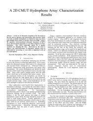
Fig. 7. Photograph of the transducer array flip-chip bonded to the IC. All<br />
256 transducer elements are functional in the flip-chip bonded device.<br />
Fig. 5. Transimpedance amplifiers located directly beneath the receiving<br />
transducer elements amplify the received signals.<br />
a 16 × 14 array of shift registers and comparators. Two<br />
rows of flip-chip bond pads on the bottom left provide<br />
the dc bias voltage required by the CMUT. The dc bias<br />
circuit is illustrated in [31]. We kept the left and top sides<br />
of the IC free of wire bond pads to provide the possibility<br />
of tiling 4 flip-chip bonded arrays together to form a 32 ×<br />
32-element array.<br />
III. Testing<br />
Fig. 6. A photograph of the IC. (a) A 16 × 16-array of flip-chip bond<br />
pads, 224 pulsers, and 32 receivers, (b) Shift register and comparator array,<br />
(c) CMUT dc-bias pads, (d) output buffers, (e) wire-bond pads.<br />
probe [58], [59] can be used to estimate heating of the<br />
probe and surrounding tissue. We targeted a power consumption<br />
of 150 mW, which we divided equally between<br />
the preamplifier and buffer. Our 150 mW power budget<br />
is greater than the 100 mW upper limit given in [44] for<br />
a 1.83-mm diameter invasive ultrasound imaging probe.<br />
However, the IC presented here is much larger than the<br />
IC described in [44]; thus, it has lower power density and<br />
provides more area for heat dissipation.<br />
For layout of the IC we divided the transmit and receive<br />
circuitry into 2 parts (Fig. 6). <strong>An</strong> array of 16 ×<br />
16 flip-chip bond pads occupies the left side of the IC.<br />
The flip-chip bond pads are 50-μm squares of top-level<br />
aluminum and have a pitch of 250 μm. One-shots and<br />
pulsers surround the flip-chip bond pads for transmitting<br />
elements. Preamplifiers surround the flip-chip bond pads<br />
for receiving elements. The right side of the IC consists of<br />
We tested the IC on its own and flip-chip bonded to<br />
a 2-D CMUT array (Fig. 7). In both cases, we packaged<br />
the device in a 121-pin PGA (pin grid array) package. A<br />
printed circuit board provided reference currents, off-chip<br />
output buffers, and digital level shifters for the IC. Digital<br />
signals for the IC were generated by a PC hosting an FP-<br />
GA-based data acquisition and signal processing system<br />
(VHS-ADC, Lyrtech Signal Processing, Quebec, Canada).<br />
This system can transfer data between the PC and FPGA<br />
(Virtex II XC2V6000, Xilinx, Inc., San Jose, CA) over the<br />
PC’s cPCI bus at rates of up to about 50 MB/s.<br />
For each new transmit beam, the PC transfers data<br />
to the FPGA. These data include values to load into the<br />
IC’s shift registers and the number of clock cycles to wait<br />
between each increment of the Gray-code counter. The<br />
FPGA then loads the IC’s shift registers and generates<br />
the 8-bit Gray-code counter values that trigger the IC’s<br />
pulsers.<br />
To observe the pulses generated by the IC’s transmit<br />
circuits, we wire bonded the flip-chip bond pads of 14<br />
transmit circuits to pins of the package. We used a lowcapacitance<br />
active probe (1156A Active Probe, Agilent<br />
Technologies, Palo Alto, CA) to measure the pulses generated<br />
by the IC for various beam focal points (Fig. 8). To<br />
determine the jitter of the generated pulses, we measured<br />
the delay between the transition of the Gray-code counter<br />
generated by the FPGA and the pulse generated by the<br />
IC. For the 14 wire-bonded pulsers, we measured delays<br />
between 40 and 48 ns; the mean delay was 44 ns with a
wygant et al.: ic and transducer for 3-d ultrasound imaging<br />
2151<br />
Fig. 9. One-shot pulse width as a function of an adjustable current provided<br />
off chip. The one-shot generates pulses as short as 100 ns.<br />
Fig. 8. The least 3 significant bits of the Gray-code counter and 5 measured<br />
pulser outputs. The top panel shows each bit of the counter with<br />
a different shade of gray. A pulser fires when the value stored in its shift<br />
register equals the global counter value. The pulser-circuit generates<br />
voltages as high as 25 V. For this measurement, we limited the pulser<br />
output voltage to 10 V to make the measurement with a low-capacitance<br />
active oscilloscope probe.<br />
standard deviation of 2.5 ns (1.3% of a period at 5 MHz).<br />
For a single pulser, the jitter between consecutive pulses<br />
was 440 ps, which indicates that most of the pulse delay<br />
variation comes from channel-to-channel variations in the<br />
comparator and one-shot circuits. Increasing the speed of<br />
the comparator circuit by using larger NMOS pulldown<br />
transistors would be one way of improving the jitter.<br />
We also measured the pulse length channel-to-channel<br />
variation. For a mean pulse width of 95 ns, the 14 measured<br />
pulse lengths varied between 92.6 and 98.5 ns with a<br />
standard deviation of 2.1 ns. Although pulse-length variation<br />
impacts the image quality less than pulse-delay variation,<br />
it could be improved by increasing the size of the<br />
one-shot capacitor, which occupies about 1% of the total<br />
circuit area for a single element, and the size of the current<br />
mirrors. To achieve much better pulse uniformity, a<br />
clock signal should dictate the pulse lengths rather than<br />
a one-shot circuit.<br />
For a 100-MHz FPGA clock, the mean error between<br />
the measured pulse delays and the ideal calculated pulse<br />
delays was 5 ns. Most of this error comes from the 10-ns<br />
FPGA clock period. For greater accuracy, we could use<br />
a higher FPGA clock rate; we tested the IC with FPGA<br />
clock rates up to the system’s maximum rate of 125 MHz.<br />
As described in [32], a clock divider implemented on the<br />
IC would also give better timing resolution.<br />
We measured the pulse width as a function of one-shot<br />
bias current (Fig. 9). The IC produced pulses as short<br />
as 100 ns, which is suitable for frequencies up to about<br />
5 MHz. For a given bias current, the IC generated longer<br />
pulses than expected from simulation, which probably<br />
resulted from a larger than expected one-shot charge<br />
capacitor [C 1 in Fig. 2 or 3(c)] and parasitic capacitance.<br />
To accommodate a wider range of transducer operating<br />
frequencies, the one-shot should be designed to accommodate<br />
larger bias currents. Properly sized, the pulser circuit<br />
can generate pulses for high-frequency arrays; for the IC<br />
used in [49], we sized the pulser circuit to generate pulses<br />
for transducers with frequencies of up to 50 MHz.<br />
Because the bandwidth of the transimpedance amplifier<br />
is sensitive to input capacitance and because it requires<br />
a high source impedance, it is difficult to measure<br />
its bandwidth electrically. A network analyzer is often<br />
used to characterize the frequency response of high-frequency<br />
transimpedance amplifiers. However, because the<br />
input impedance of the amplifier presented here is several<br />
kilohms, it is difficult to measure the S 11 parameter<br />
needed to determine the gain. In [44], the authors included<br />
a test structure on the IC to measure the bandwidth. In<br />
this paper, because the simulated bandwidth significantly<br />
exceeds the frequency content of the transducers used for<br />
imaging, we assume that the amplifier’s response did not<br />
impact the frequency content of the measured ultrasound<br />
echoes.<br />
We tested the IC in combination with a CMUT array<br />
by flip-chip bonding a 16 × 16-element CMUT array to<br />
the IC. To prepare the IC for flip-chip bonding, an electroless<br />
plating process creates a 5-μm thick Ni/Au layer on<br />
the IC pads; a solder-jetting process then deposits 80-μm<br />
diameter solder balls on the pads (Pac Tech USA, Santa<br />
Clara, CA) [31]. To test the device in immersion, we attached<br />
a small plastic tank to the IC’s PGA package and<br />
filled it with vegetable oil. Using vegetable oil in place of<br />
water enables us to test the device in immersion without<br />
having to electrically insulate the CMUT and IC. For testing<br />
in water, we have shown that parylene and polydimethylsiloxane<br />
(PDMS) effectively insulate the CMUT [60].<br />
To test the functionality of each element and its corresponding<br />
electronics, we fired each element individually<br />
and recorded the echoes from the surface of the oil detected<br />
by the 32 receiving elements. We observed an echo<br />
for every transmitting and receiving element, which demonstrates<br />
the functionality of the IC and every element of<br />
the array.<br />
To measure the focusing capability of the flip-chip<br />
bonded device, we transmitted beams with various focal<br />
points and measured the pressure at the focal point with<br />
a hydrophone. For a focal point at 4 mm on-axis from the<br />
center of the array, we measured a peak-to-peak pressure<br />
of 850 kPa, which is about 120 times the pressure produced<br />
by a single element in the center of the array (Fig.<br />
10). At 4 mm, the focusing gain is less than 224 (the total<br />
number of transmitting elements) because those elements<br />
at the edge, which are at greater angles relative to the hydrophone,<br />
contribute less to the pressure at the focal point<br />
than those elements in the center. Moving the hydrophone
2152 <strong>IEEE</strong> Transactions on Ultrasonics, Ferroelectrics, and Frequency Control, vol. 56, no. 10, October 2009<br />
Fig. 10. We measured the pressure at a focal point located 4 mm on-axis<br />
from the array’s center. (a) At the focal point, the transmitted pulses<br />
add together. For a center frequency of 2.2 MHz, the hydrophone output<br />
corresponds to 850 kPa peak-to-peak, which is about 120 times the pressure<br />
from a single element. (b) The Fourier transform of the measured<br />
signal at the focal point.<br />
Fig. 11. Comparison between images of 5 fishing line segments acquired<br />
with the single-channel IC described in [31] and the IC described in<br />
this work. (a) Image from [31] acquired using 16 averages. (b) Image<br />
acquired using the IC described in this paper without averaging and using<br />
60 beams spanning 90°. The transmit focus distance is 15 mm. We<br />
increased the spacing between the 2 closest lines from 0.8 to 1.2 mm for<br />
the multichannel-IC image; otherwise, the wire phantoms are identical.<br />
Both images have 50-dB dynamic range and a gamma value of 0.8. (c)<br />
Axial image profile aligned to the center line segment. (d) Lateral image<br />
profile aligned to the center line segment. The image acquired with<br />
the multichannel IC demonstrates significantly improved dynamic range<br />
with the capability of acquiring images at a much higher frame rate.<br />
A lower transducer frequency (2.2 MHz compared with 5.1 MHz) and<br />
the different transmit and receive array configuration [43] results in decreased<br />
resolution in the image acquired with the multichannel IC.<br />
to distances further from the IC shows focusing gains approaching<br />
224.<br />
To determine the minimum detectable pressure for a<br />
combined CMUT element and preamplifier, we measured<br />
the electrical output noise and divided the result by the<br />
measured receive sensitivity. To determine receive sensitivity,<br />
we used a hydrophone to measure the pressure generated<br />
by a single element at a distance of 22.5 mm. We<br />
then measured the pulse-echo signal from the oil-air interface<br />
for a 2-way distance of 22.5 mm. The amplitude of<br />
the pulse-echo signal divided by the measured pressure<br />
equals the receive sensitivity assuming the oil-air interface<br />
is a perfect reflector. We measured the electrical noise at<br />
the output of the discrete buffer and amplifier that follow<br />
the IC’s output using a spectrum analyzer (2712 Spectrum<br />
<strong>An</strong>alyzer, Tektronix, Beaverton, OR). At 4.4 MHz,<br />
we measured a 414 mV/kPa receive sensitivity and an<br />
output electrical noise of 380 nV/ÖHz, which results in an<br />
input referred noise of 0.9 mPa/ÖHz.<br />
Changing the CMUT bias voltage, and thus the<br />
CMUT’s sensitivity, results in negligible changes in the<br />
measured noise. This invariance indicates that electrical<br />
sources dominate the total noise. The noise of the 215-kΩ<br />
feedback resistor (280 fA/ÖHz) dominates the noise of the<br />
transimpedance amplifier. Increasing the feedback resistor<br />
value, at the expensive of bandwidth, or using an amplifier<br />
topology with capacitive feedback are options for reducing<br />
the preamplifier noise.<br />
To assess the imaging capability of the IC, we acquired<br />
images of a wire phantom constructed using 150-μm diameter<br />
fishing line. To acquire the images, we programmed<br />
the PC and FPGA system to generate the desired transmit<br />
beams. <strong>An</strong> FPGA-implemented real-time beamformer<br />
reconstructed the received data sampled at 100 MHz. The<br />
beamformer uses a standard delay-and-sum algorithm. Fig.<br />
11 compares the acquired images with those obtained with<br />
the single-channel IC presented in [31]; Fig. 12 shows the<br />
volume-rendered image. The images obtained with no averaging<br />
have about 23 dB better SNR than those obtained<br />
using the single-channel IC using 16 averages. Based on<br />
the number of transmit and receive elements, we expect<br />
about a 26 dB improvement in SNR [43]. About 6.5 dB of<br />
improvement is offset by increased diffraction and attenuation<br />
losses at the CMUT array’s lower center frequency<br />
(2.2 MHz compared with 5.1 MHz in [31]). However, the<br />
higher source pressure of the CMUT array used in this<br />
study compensates for the lost improvement.
wygant et al.: ic and transducer for 3-d ultrasound imaging<br />
2153<br />
Fig. 12. Scan converted and rendered volume of five 150-μm diameter<br />
fishing line segments. The acquired volume spans 60° in the horizontal<br />
direction (32 beams) and 30° (16 beams) in the vertical direction. In<br />
the range direction, the volume extends from 5 to 25 mm. The image is<br />
shown with 40 dB of dynamic range. The first 25 dB of dynamic range<br />
has high transparency to prevent occlusion of the line segments.<br />
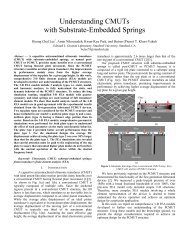
Fig. 14. Two orthogonal 2-D image cross sections of a left atrium heart<br />
phantom and a photograph of the phantom illustrating the imaged location.<br />
The ultrasound images have 25 dB dynamic range and a gamma<br />
value of 0.8. They span 60° and range from 10 to 25 mm.<br />
Fig. 13. Image acquired using only transmit beamforming. To assess the<br />
transmit beamforming capability of the IC, we acquired an image using<br />
all 224 transmit elements and a single receive channel. The imaging contains<br />
64 beams that scan a 60° sector angle. (a) Image of a wire phantom<br />
shown with 30-dB dynamic range and a gamma value of 0.8. (b) Profile<br />
of the center wire.<br />
<strong>With</strong> 16 averages, the single-channel IC requires 4096<br />
transmits to obtain a full 3-D volume, which compares to<br />
about 1000 transmits for the multichannel IC. The multichannel<br />
IC also offers more ways of achieving high frame<br />
rates; for example, using defocused transmit beams or acquiring<br />
2-D cross sections would increase the frame rate.<br />
To separately evaluate the IC’s transmit beamforming<br />
capability, we acquired an image using a single receive<br />
channel. Fig. 13 demonstrates that the IC transmits a<br />
focused beam of ultrasound. Finally, we acquired orthogonal<br />
2-D cross-section images (B-scans) of a heart phantom<br />
(Fig. 14).<br />
The results presented in this paper demonstrate that<br />
the IC can transmit on all 224 elements with programmable<br />
delays and can be used to generate arbitrarily focused<br />
beams of ultrasound. <strong>Flip</strong>-chip bonded to a 256-element<br />
2-D CMUT array, every transmit and receive element of<br />
the device is functional and can be used for 3-D imaging.<br />
For real-time imaging, we developed a real-time data acquisition<br />
and image reconstruction system. Assuming an<br />
imaging depth of 3 cm for intracavital imaging and the<br />
use of 40 × 40 transmit beams spanning 90° × 90°, up to<br />
12 volumes per second could be acquired. Higher volume<br />
rates can be obtained by transmitting fewer defocused<br />
transmit beams or reducing the size of the image volume.<br />
For improved SNR and for imaging techniques such as<br />
harmonic imaging, ultrasound systems are increasingly using<br />
coded excitation pulses [61]. To generate coded excitations,<br />
some of the pulsers would need to be retriggered<br />
while others are still firing, which is not possible with the<br />
dynamic logic comparator and one-shot circuit used for<br />
the IC presented here. Using retriggerable comparators<br />
and one-shots, which could have the drawback of consuming<br />
more area, the same general IC architecture could be<br />
used to transmit more complex waveforms.<br />
In summary, the IC presented in this paper provides<br />
significantly better image SNR than the IC we demonstrated<br />
in [31]. In addition, it shows how a large number of<br />
transmit elements can be utilized with a minimal number<br />
of signal lines, which is a step toward a compact and integrated<br />
3-D ultrasound imaging system.<br />
IV. Conclusion<br />
Acknowledgment<br />
National Semiconductor (Santa Clara, CA) fabricated<br />
the ICs and provided circuit design support. X. Zhuang
2154 <strong>IEEE</strong> Transactions on Ultrasonics, Ferroelectrics, and Frequency Control, vol. 56, no. 10, October 2009<br />
and S. Ergun fabricated the CMUT arrays for this work.<br />
Work was performed in part at the Stanford Nanofabrication<br />
Facility (a member of the National Nanotechnology<br />
Infrastructure Network) which is supported by the National<br />
Science Foundation under Grant ECS-9731293, its<br />
lab members, and the industrial members of the Stanford<br />
Center for <strong>Integrated</strong> Systems. Pac Tech USA, Inc. (Santa<br />
Clara, CA) provided solder-jetting and electroless Ni/Au<br />
bumping services. Dr. D. Sahn of the Oregon Health and<br />
Science University provided the heart phantom.<br />
References<br />
[1] L. F. Goncalves, W. Lee, J. Espinoza, and R. Romero, “Three- and<br />
4- dimensional ultrasound in obstetric practice: Does it help” J.<br />
Ultrasound Med., vol. 24, no. 12, pp. 1599–1624, 2005.<br />
[2] B. R. Benacerraf, T. D. Shipp, and B. Bromley, “Three-dimensional<br />
US of the fetus: Volume imaging,” Radiology, vol. 238, no. 3, pp.<br />
988–996, 2006.<br />
[3] I. S. Salgo, “Three-dimensional echocardiographic technology,” Cardiol.<br />
Clin., vol. 25, no. 2, pp. 231–239, 2007.<br />
[4] J. Hung, R. Lang, F. Flachskampf, S. K. Shernan, M. L. McCulloch,<br />
D. B. Adams, J. Thomas, M. Vannan, and T. Ryan, “3-D echocardiography:<br />
A review of the current status and future directions,” J.<br />
Am. Soc. Echocardiogr., vol. 20, no. 3, pp. 213–233, 2007.<br />
[5] B. R. Benacerraf, T. D. Shipp, and B. Bromley, “Improving the efficiency<br />
of gynecologic sonography with 3-dimensional volumes: A<br />
pilot study,” J. Ultrasound Med., vol. 25, no. 2, pp. 165–171, 2006.<br />
[6] S. W. Smith, H. R. Pavy, and O. T. von Ramm, “High-speed ultrasound<br />
volumetric imaging system. I. Transducer design and beam<br />
steering,” <strong>IEEE</strong> Trans. Ultrason. Ferroelectr. Freq. Control, vol. 38,<br />
no. 2, pp. 100–108, 1991.<br />
[7] L. F. Goncalves, J. Espinoza, J. P. Kusanovic, W. Lee, J. K. Nien, J.<br />
Santolaya-Forgas, G. Mari, M. C. Treadwell, and R. Romero, “Applications<br />
of 2-dimensional matrix array for 3- and 4-dimensional<br />
examination of the fetus: A pictorial essay,” J. Ultrasound Med., vol.<br />
25, no. 6, pp. 745–755, 2006.<br />
[8] Precision Interconnect, “MODULUS3 cable assemblies data sheet,”<br />
Berwyn, PA, 2004.<br />
[9] B. Haider, “Power drive circuits for diagnostic medical ultrasound,”<br />
in 2006 <strong>IEEE</strong> Int. Symp. Power Semiconductor Devices and ICs,<br />
2006, pp. 1–8.<br />
[10] U.S. Department of Health and Human Services Food and Drug<br />
Administration, Center for Devices and Radiological Health, “Information<br />
for manufacturers seeking marketing clearance of diagnostic<br />
ultrasound systems and transducers,” U.S. Department of Health<br />
and Human Services, Washington, DC, 1997.<br />
[11] NEMA, “Standard for real-time display of thermal and mechanical<br />
acoustic output indices on diagnostic ultrasound equipment,” National<br />
Electrical Manufacturers Association, Rosslyn, VA, 2004.<br />
[12] J. G. Abbott, “Rationale and derivation of MI and TI—A review,”<br />
Ultrasound Med. Biol., vol. 25, no. 3, pp. 431–441, 1999.<br />
[13] D. K. Peterson and G. S. Kino, “Real-time digital image reconstruction:<br />
A description of imaging hardware and an analysis of quantization<br />
errors,” <strong>IEEE</strong> Trans. Sonics Ultrason., vol. 31, no. 4, pp.<br />
337–351, 1984.<br />
[14] S. Holm and K. Kristoffersen, “<strong>An</strong>alysis of worst-case phase quantization<br />
sidelobes in focused beamforming,” <strong>IEEE</strong> Trans. Ultrason.<br />
Ferroelectr. Freq. Control, vol. 39, no. 5, pp. 593–599, 1992.<br />
[15] J. Jensen, “Field: A program for simulating ultrasound systems,”<br />
Med. Biol. Eng. Comput., vol. 34, pp. 351–353, 1996.<br />
[16] T. L. Rhyne, “Characterizing ultrasonic transducers using radiation<br />
efficiency and reception noise figure,” <strong>IEEE</strong> Trans. Ultrason. Ferroelectr.<br />
Freq. Control, vol. 45, no. 3, pp. 559–566, 1998.<br />
[17] D. P. Shattuck, M. D. Weinshenker, S. W. Smith, and O. T. von<br />
Ramm, “Explososcan: A parallel processing technique for high speed<br />
ultrasound imaging with linear phased arrays,” J. Acoust. Soc. Am.,<br />
vol. 75, no. 4, pp. 1273–1282, 1984.<br />
[18] O. T. von Ramm, S. W. Smith, and H. R. Pavy, “High-speed ultrasound<br />
volumetric imaging system. II. Parallel processing and image<br />
display,” <strong>IEEE</strong> Trans. Ultrason. Ferroelectr. Freq. Control, vol. 38,<br />
no. 2, pp. 109–115, 1991.<br />
[19] M. Greenstein, P. Lum, H. Yoshida, and M. Seyed-Bolorforosh, “A<br />
2.5 MHz 2-D array with Z-axis backing,” in Proc. 1996 <strong>IEEE</strong> Ultrasonics<br />
Symp., vol. 2, 1996, pp. 1513–1516.<br />
[20] R. E. Davidsen and S. W. Smith, “Two-dimensional arrays for medical<br />
ultrasound using multilayer flexible circuit interconnection,”<br />
<strong>IEEE</strong> Trans. Ultrason. Ferroelectr. Freq. Control, vol. 45, no. 2, pp.<br />
338–348, 1998.<br />
[21] S. W. Smith and E. D. Light, “Two-dimensional array transducers<br />
using thick film connection technology,” <strong>IEEE</strong> Trans. Ultrason. Ferroelectr.<br />
Freq. Control, vol. 40, no. 6, pp. 727–734, 1993.<br />
[22] L. Daane and M. Greenstein, “A demountable interconnect system<br />
for a 50 × 50 ultrasonic imaging transducer array,” <strong>IEEE</strong> Trans. Ultrason.<br />
Ferroelectr. Freq. Control, vol. 44, no. 5, pp. 978–982, 1997.<br />
[23] J. O. Fiering, P. Hultman, W. Lee, E. D. Light, and S. W. Smith,<br />
“High-density flexible interconnect for two-dimensional ultrasound<br />
arrays,” <strong>IEEE</strong> Trans. Ultrason. Ferroelectr. Freq. Control, vol. 47,<br />
no. 3, pp. 764–770, 2000.<br />
[24] B. Savord and R. Solomon, “Fully sampled matrix transducer for<br />
real time 3-D ultrasonic imaging,” in 2003 <strong>IEEE</strong> Symp. Ultrasonics,<br />
vol. 1, 2003, pp. 945–953.<br />
[25] W. Lee, S. Idriss, P. Wolf, and S. Smith, “A miniaturized catheter<br />
2-D array for real-time, 3-D intracardiac echocardiography,” <strong>IEEE</strong><br />
Trans. Ultrason. Ferroelectr. Freq. Control, vol. 51, no. 10, pp. 1334–<br />
1346, 2004.<br />
[26] P. C. Eccardt and K. Niederer, “Micromachined ultrasound transducers<br />
with improved coupling factors from a CMOS compatible<br />
process,” Ultrasonics, vol. 38, no. 1-8, pp. 774–780, 2000.<br />
[27] R. Noble, R. Davies, M. Day, L. Koker, D. King, K. Brunson, A.<br />
Jones, J. McIntosh, D. Hutchins, T. Robertson, and P. Saul, “Costeffective<br />
and manufacturable route to the fabrication of high-density<br />
2-D micromachined ultrasonic transducer arrays and (CMOS) signal<br />
conditioning electronics on the same silicon substrate,” in 2001<br />
<strong>IEEE</strong> Ultrasonics Symp., vol. 2, 2001, pp. 941–944.<br />
[28] Y. Mo, T. Tanaka, K. Inoue, K. Yamashita, and Y. Suzuki, “Frontend<br />
processor using BBD distributed delay-sum architecture for<br />
micromachined ultrasonic sensor array,” J. Microelectromech. Syst.,<br />
vol. 12, no. 4, pp. 506–512, 2003.<br />
[29] C. Daft, S. Calmes, D. da Graca, K. Patel, P. Wagner, and I. Ladabaum,<br />
“Microfabricated ultrasonic transducers monolithically integrated<br />
with high voltage electronics,” in 2004 <strong>IEEE</strong> Ultrasonics<br />
Symp., vol. 1, 2004, pp. 493–496.<br />
[30] C. Daft, P. Wagner, B. Bymaster, S. Panda, K. Patel, and I. Ladabaum,<br />
“cMUTs and electronics for 2-D and 3-D imaging: monolithic<br />
integration, in-handle chip sets and system implications,” in 2005<br />
<strong>IEEE</strong> Ultrasonics Symp., vol. 1, 2005, pp. 463–474.<br />
[31] I. Wygant, X. Zhuang, D. Yeh, O. Oralkan, A. Ergun, M. Karaman,<br />
and B. Khuri-Yakub, “Integration of 2-D CMUT arrays with<br />
front-end electronics for volumetric ultrasound imaging,” <strong>IEEE</strong><br />
Trans. Ultrason. Ferroelectr. Freq. Control, vol. 55, no. 2, pp. 327–<br />
342, 2008.<br />
[32] J. V. Hatfield and K. S. Chai, “A beam-forming transmit ASIC for<br />
driving ultrasonic arrays,” Sens. Actuators A, vol. 92, no. 1-3, pp.<br />
273–279, 2001.<br />
[33] I. G. Mina, H. Kim, I. Kim, S. K. Park, K. Choi, T. N. Jackson, R.<br />
L. Tutwiler, and S. Trolier-McKinstry, “High frequency piezoelectric<br />
MEMS ultrasound transducers,” <strong>IEEE</strong> Trans. Ultrason. Ferroelectr.<br />
Freq. Control, vol. 54, no. 12, pp. 2422–2430, 2007.<br />
[34] T. Halvorsrod, W. Luzi, and T. S. Lande, “A log-domain μbeamformer<br />
for medical ultrasound imaging systems,” <strong>IEEE</strong> Trans. <strong>Circuit</strong>s Syst.<br />
I, Regul. Pap., vol. 52, no. 12, pp. 2563–2575, 2005.<br />
[35] B. Stefanelli, I. O’Connor, L. Quiquerez, A. Kaiser, and D. Billet,<br />
“<strong>An</strong> analog beam-forming circuit for ultrasound imaging using<br />
switched current delay lines,” <strong>IEEE</strong> J. Solid-State <strong>Circuit</strong>s, vol. 35,<br />
no. 2, pp. 202–211, 2000.<br />
[36] M. Yaowu, T. Tanaka, S. Arita, A. Tsuchitani, K. Inoue, and Y.<br />
Suzuki, “Pipelined delay-sum architecture based on bucket-brigade<br />
devices for on-chip ultrasound beamforming,” <strong>IEEE</strong> J. Solid-State<br />
<strong>Circuit</strong>s, vol. 38, no. 10, pp. 1754–1757, 2003.<br />
[37] J. R. Talman, S. L. Garverick, and G. R. Lockwood, “<strong>Integrated</strong><br />
circuit for high-frequency ultrasound annular array,” in Proc. 2003<br />
<strong>IEEE</strong> Custom <strong>Integrated</strong> <strong>Circuit</strong>s Conf., 2003, pp. 477–480.<br />
[38] J. R. Talman, S. L. Garverick, C. E. Morton, and G. R. Lockwood,<br />
“Unit-delay focusing architecture and integrated-circuit implementation<br />
for high-frequency ultrasound,” <strong>IEEE</strong> Trans. Ultrason. Ferroelectr.<br />
Freq. Control, vol. 50, no. 11, pp. 1455–1463, 2003.<br />
[39] K. Kaviani, O. Oralkan, P. Khuri-Yakub, and B. Wooley, “A multichannel<br />
pipeline analog-to-digital converter for an integrated 3-D
wygant et al.: ic and transducer for 3-d ultrasound imaging<br />
ultrasound imaging system,” <strong>IEEE</strong> J. Solid-State <strong>Circuit</strong>s, vol. 38,<br />
no. 7, pp. 1266–1270, 2003.<br />
[40] M. I. Fuller, K. Ranganathan, S. Zhou, T. N. Blalock, J. Hossack,<br />
and W. F. Walker, “Experimental system prototype of a portable,<br />
lowcost, c-scan ultrasound imaging device,” <strong>IEEE</strong> Trans. Biomed.<br />
Eng., vol. 55, no. 2, pp. 519–530, 2008.<br />
[41] K. Hara, J. Sakano, M. Mori, S. Tamano, R. Sinomura, and K.<br />
Yamazaki, “A new 80 V 32 × 32ch low loss multiplexer LSI for a<br />
3-D ultrasound imaging system,” in Proc. 17th Int. Symp. Power<br />
Semiconductor Devices and ICs, 2005, pp. 359–362.<br />
[42] L. Ye-Ming, R. Wodnicki, N. Chandra, and N. Rao, “<strong>An</strong> integrated<br />
90 V switch array for medical ultrasound applications,” in 2006<br />
<strong>IEEE</strong> Custom <strong>Integrated</strong> <strong>Circuit</strong>s Conf., 2006, pp. 269–272.<br />
[43] I. Wygant, M. Karaman, O. Oralkan, and B. Khuri-Yakub, “<strong>Beamforming</strong><br />
and hardware design for a multichannel front-end integrated<br />
circuit for real-time 3-D catheter-based ultrasonic imaging,”<br />
in SPIE Medical Imaging 2006, vol. 6147, San Diego, CA,<br />
2006.<br />
[44] W. C. Black Jr. and D. N. Stephens, “CMOS chip for invasive ultrasound<br />
imaging,” <strong>IEEE</strong> J. Solid-State <strong>Circuit</strong>s, vol. 29, no. 11, pp.<br />
1381–1387, 1994.<br />
[45] E. D. Light, S. F. Idriss, P. D. Wolf, and S. W. Smith, “Real-time<br />
three-dimensional intracardiac echocardiography,” Ultrasound Med.<br />
Biol., vol. 27, no. 9, pp. 1177–1183, 2001.<br />
[46] E. C. Pua, S. F. Idriss, P. D. Wolf, and S. W. Smith, “Real-time 3-D<br />
transesophageal echocardiography,” Ultrason. Imaging, vol. 26, pp.<br />
217–232, 2004.<br />
[47] O. Oralkan, A. Ergun, J. Johnson, M. Karaman, U. Demirci, K.<br />
Kaviani, T. Lee, and B. Khuri-Yakub, “Capacitive micromachined<br />
ultrasonic transducers: Next-generation arrays for acoustic imaging”<br />
<strong>IEEE</strong> Trans. Ultrason. Ferroelectr. Freq. Control, vol. 49, no.<br />
11, pp. 1596–1610, 2002.<br />
[48] D. M. Mills, “Medical imaging with capacitive micromachined ultrasound<br />
transducer (cMUT) arrays,” in 2004 <strong>IEEE</strong> Ultrasonics Symp.,<br />
vol. 1, 2004, pp. 384–390.<br />
[49] D. T. Yeh, O. Oralkan, I. O. Wygant, M. O’Donnell, and B. T. Khuri-Yakub,<br />
“3-D ultrasound imaging using a forward-looking CMUT<br />
ring array for intravascular/intracardiac applications,” <strong>IEEE</strong> Trans.<br />
Ultrason. Ferroelectr. Freq. Control, vol. 53, no. 6, pp. 1202–1211,<br />
2006.<br />
[50] O. Oralkan, S. T. Hansen, B. Bayram, G. G. Yaralioglu, A. S. Ergun,<br />
and B. T. Khuri-Yakub, “High-frequency CMUT arrays for<br />
high-resolution medical imaging,” in 2004 <strong>IEEE</strong> Ultrasonics Symp.,<br />
vol. 1, 2004, pp. 399–402.<br />
[51] C.-H. Cheng, A. Ergun, and B. Khuri-Yakub, “Electrical throughwafer<br />
interconnects with 0.05 picofarads parasitic capacitance on<br />
400 μm thick silicon substrates,” in Solid-State Sensor and Actuator<br />
Workshop, Hilton Head Island, 2002.<br />
[52] X. Zhuang, I. O. Wygant, D. S. Lin, M. Kupnik, O. Oralkan, and B.<br />
T. Khuri-Yakub, “Trench-isolated CMUT arrays with a supporting<br />
frame: Characterization and imaging results,” in 2007 <strong>IEEE</strong> Ultrasonics<br />
Symp., 2007, pp. 507–510.<br />
[53] M. Declerq, M. Schubert, and F. Clement, “5 V-to-75 V CMOS output<br />
interface circuits,” in 1993 <strong>IEEE</strong> Int. Solid-State <strong>Circuit</strong>s Conf.,<br />
1993, pp. 162–163, 283.<br />
[54] A. Nikoozadeh, B. Bayram, G. Yaralioglu, and B. Khuri-Yakub,<br />
“<strong>An</strong>alytical calculation of collapse voltage of CMUT membrane<br />
[capacitive micromachined ultrasonic transducers],” in 2004 <strong>IEEE</strong><br />
Ultrasonics Symp., vol. 1, 2004, pp. 256–259.<br />
[55] I. Ladabaum, J. Xuecheng, H. T. Soh, A. Atalar, and B. T. Khuri-<br />
Yakub, “Surface micromachined capacitive ultrasonic transducers,”<br />
<strong>IEEE</strong> Trans. Ultrason. Ferroelectr. Freq. Control, vol. 45, no. 3, pp.<br />
678–690, 1998.<br />
[56] A. Lohfink and P. C. Eccardt, “Linear and nonlinear equivalent circuit<br />
modeling of CMUTs,” <strong>IEEE</strong> Trans. Ultrason. Ferroelectr. Freq.<br />
Control, vol. 52, no. 12, pp. 2163–2172, 2005.<br />
[57] J. Graeme, Photodiode Amplifiers: Op Amp Solutions. New York:<br />
McGraw Hill, 1995.<br />
[58] D. N. Stephens, K. K. Shung, J. Cannata, J. Zhao, R. Chia, H.<br />
Nguyen, K. Thomenius, A. Dentinger, D. G. Wildes, X. Chen, M.<br />
O’Donnell, R. I. Lowe, J. Pemberton, G. H. Burch, and D. J. Sahn,<br />
“Clinical application and technical challenges for intracardiac ultrasound<br />
imaging catheter based ICE imaging with EP mapping,” in<br />
2004 <strong>IEEE</strong> Ultrasonics Symp., vol. 1, 2004, pp. 772–777.<br />
[59] A. S. Ergun, S. Barnes, and E. Gardner, “<strong>An</strong> assessment of the thermal<br />
efficiency of capacitive micromachined ultrasonic transducers,”<br />
in 2007 <strong>IEEE</strong> Ultrasonics Symp., 2007, pp. 420–423.<br />
2155<br />
[60] X. Zhuang, A. Nikoozadeh, M. Beasley, G. Yaralioglu, B. Khuri-<br />
Yakub, and B. L. Pruitt, “Biocompatible coatings for CMUTs in a<br />
harsh, aqueous environment,” J. Microelectromech. Syst., vol. 17, no.<br />
5, pp. 994–1001, 2007.<br />
[61] T. Misaridis and J. Jensen, “Use of modulated excitation signals in<br />
medical ultrasound. Part I: Basic concepts and expected benefits,”<br />
<strong>IEEE</strong> Trans. Ultrason. Ferroelectr. Freq. Control, vol. 52, no. 2, pp.<br />
177–191, 2005.<br />
Ira O. Wygant received his B.S. degree in electrical<br />
engineering with a cross-college major in<br />
computer science from the University of Wyoming,<br />
Laramie, WY, in 1999. He received his M.S.<br />
degree in electrical engineering from Stanford University,<br />
Stanford, CA, in 2002 and his Ph.D in<br />
electrical engineering from Stanford University in<br />
2008. After finishing his Ph.D, he joined National<br />
Semiconductor’s research labs in Santa Clara, CA.<br />
His research interests include integrated circuit<br />
design, ultrasound imaging, and MEMs design<br />
and fabrication as they relate to capacitive micromachined ultrasound<br />
transducers.<br />
Nafis Jamal received his B.S. degrees in electrical<br />
engineering and physics from Stanford University,<br />
Stanford, CA in 2008. He received his M.S.<br />
degree in electrical engineering from Stanford University<br />
in 2008 through the coterminal program.<br />
He is currently pursuing a Ph.D. degree in electrical<br />
engineering at Stanford University. Nafis has<br />
had internships with Sun Microsystems Labs. His<br />
research interests include ultrasound imaging and<br />
FPGA design for ultrasonic systems.<br />
Hyunjoo J. Lee received the B.S. degree in Electrical<br />
Engineering and Computer Science and the<br />
M.Eng degree in Electrical Engineering, both from<br />
the Massachusetts Institute of Technology in 2004<br />
and 2005, respectively. She is currently pursuing<br />
the Ph.D. degree in Electrical Engineering at<br />
Stanford University.<br />
From 2004 to 2005, she was a MIT VI-A fellow<br />
at <strong>An</strong>alog Devices, Inc, Wilmington, MA, where<br />
she studied continuous-time signal-delta ADCs. In<br />
2008, she was a student intern at National Semiconductor,<br />
Santa Clara, CA, where she developed an oscillator circuit<br />
that interfaces with a capacitive micromachined ultrasonic transducer<br />
(CMUT) for chemical sensing. Her research interests include sensor interface<br />
circuit design and bio/chemical sensor design. She is a member of<br />
the Eta Kappa Nu and Tau Beta Pi honor societies.<br />
Amin Nikoozadeh (S’03) received the B.S. degree<br />
from Sharif University of Technology, Tehran,<br />
Iran, in 2002 and the M.S. degree from Stanford<br />
University, Stanford, CA, in 2004, both in electrical<br />
engineering. He is currently pursuing the Ph.D.<br />
degree in electrical engineering at Stanford University.<br />
His research interests include medical ultrasound<br />
imaging, image-guided therapeutics,<br />
MEMS, and analog circuit design.
2156 <strong>IEEE</strong> Transactions on Ultrasonics, Ferroelectrics, and Frequency Control, vol. 56, no. 10, October 2009<br />
Ömer Oralkan received the B.S. degree from<br />
Bilkent University, <strong>An</strong>kara, Turkey, in 1995, the<br />
M.S. degree from Clemson University, Clemson,<br />
SC, in 1997, and the Ph.D. degree from Stanford<br />
University, Stanford, CA, in 2004, all in electrical<br />
engineering. He joined the research staff at the E.<br />
L. Ginzton Laboratory of Stanford University in<br />
2004 as an Engineering Research Associate. He<br />
was promoted to the rank of Senior Research Engineer<br />
in 2007. He also serves as an Adjunct Professor<br />
of Electrical Engineering at Santa Clara<br />
University, Santa Clara, CA. His past and present research interests include<br />
analog and digital circuit design, semiconductor device physics and<br />
fabrication, micromachined sensors and actuators, and medical imaging.<br />
His current research focuses on the design and implementation of integrated<br />
systems for catheter-based medical imaging applications, photoacoustic<br />
imaging, and chemical and biological sensor arrays. Dr. Oralkan<br />
has authored and co-authored over 100 publications and received the<br />
2002 Outstanding Paper Award of the <strong>IEEE</strong> Ultrasonics, Ferroelectrics,<br />
and Frequency Control Society. He is a member of the <strong>IEEE</strong>.<br />
Mustafa Karaman (S’88-M’93) received the BS<br />
degree from the Middle East Technical University<br />
(<strong>An</strong>kara, Turkey) in 1986, and the MS and PhD<br />
degrees from Bilkent University (<strong>An</strong>kara, Turkey),<br />
in 1988 and 1992, respectively, all in electrical and<br />
electronics engineering. He was a post-doctoral<br />
fellow in the Biomedical Ultrasonics Laboratory of<br />
the University of Michigan (<strong>An</strong>n Arbor, MI) between<br />
1993-94. He has worked at the BU (<strong>An</strong>kara,<br />
Turkey) as an associate professor and served in<br />
founding the faculty of engineering. He was with<br />
the E.L. Ginzton Laboratory at Stanford University (Stanford, CA) as a<br />
visiting faculty between 2000-02. He is currently working as a professor<br />
in the Department of Electronics Engineering of Işık University (Istanbul,<br />
Turkey) since 2002.<br />
He has authored over one hundred papers in refereed journals and<br />
conferences. He received the <strong>IEEE</strong> UFFC Society 2002 Outstanding Paper<br />
Award as a co-author, and the 1996 H. Tuğaç Foundation Research<br />
Award of TUBITAK of Turkey.<br />
His research interests include signal processing, medical ultrasonic<br />
imaging, and integrated circuit design.<br />
Butrus (Pierre) T. Khuri-Yakub is a Professor<br />
of Electrical Engineering at Stanford University,<br />
Stanford, CA. He received the B.S. degree<br />
from the American University of Beirut, the M.S.<br />
degree from Dartmouth College, Hanover, NH,<br />
and the Ph.D. degree from Stanford University, all<br />
in electrical engineering. He was a Research Associate<br />
(1975-1978) then Senior Research Associate<br />
(1978-1982) at the E. L. Ginzton Laboratory<br />
of Stanford University and was promoted to the<br />
rank of Professor of Electrical Engineering in<br />
1982. His current research interests include medical ultrasound imaging<br />
and therapy, micromachined ultrasonic transducers, smart biofluidic<br />
channels, microphones, ultrasonic fluid ejectors, and ultrasonic nondestructive<br />
evaluation, imaging and microscopy. He has authored over 450<br />
publications and has been principal inventor or co-inventor of 78 U.S.<br />
and International issued patents. He was awarded the Medal of the City<br />
of Bordeaux in 1983 for his contributions to Nondestructive Evaluation,<br />
the Distinguished Advisor Award of the School of Engineering at Stanford<br />
University in 1987, the Distinguished Lecturer Award of the <strong>IEEE</strong><br />
UFFC society in 1999, a Stanford University Outstanding Inventor<br />
Award in 2004, and a Distinguished Alumnus Award of the School of<br />
Engineering of the American University of Beirut in 2005.