AFM study of morphological changes associated with ...
AFM study of morphological changes associated with ...
AFM study of morphological changes associated with ...

You also want an ePaper? Increase the reach of your titles
YUMPU automatically turns print PDFs into web optimized ePapers that Google loves.
J Solid State Electrochem (2008) 12:739–746 743<br />
Fig. 4 Cyclic voltammogram obtained when a drop-casted TCNQ<br />
crystal modified gold slide electrode is in contact <strong>with</strong> aqueous 0.1 M<br />
CuSO 4 solution. The potential range is 0.3 to −0.12 V, and the scan<br />
rate is 20 mV s −1 . First cycle (solid line), second cycle (dashed line);<br />
2.5 cycles (dotted line)<br />
exhaustive cycling <strong>of</strong> the potential has been presented<br />
previously by Neufeld et al. [24].<br />
To confirm the effect <strong>of</strong> the potential cycling rather than<br />
time in determining the morphology after CuTCNQ Phase I<br />
was formed, the sample was left in solution overnight, and<br />
a new <strong>AFM</strong> observation was made. No change in the <strong>AFM</strong><br />
image was identified.<br />
Co[TCNQ] 2 (H 2 O) 2<br />
The procedure adopted to obtain <strong>AFM</strong> images <strong>of</strong> the TCNQ<br />
to Co[TCNQ] 2 (H 2 O) 2 transformation was the same as<br />
discussed for formation <strong>of</strong> CuTCNQ. However, in this<br />
case, it was not easy to obtain good quality images from the<br />
first few cycles <strong>of</strong> the potential. The reason for this is<br />
thought to be related to <strong>AFM</strong> imaging problems encountered<br />
from the presence <strong>of</strong> initially generated small Co<br />
[TCNQ] 2 (H 2 O) 2 rod-shaped nucleus crystals protruding<br />
outwards from the surface. Nevertheless, after reductive<br />
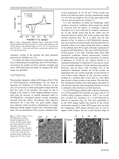
electrolysis for 5 min (Fig. 5a), good quality images<br />
were obtained, which revealed a predominance <strong>of</strong> evenly<br />
dispersed rod-like shaped crystals <strong>with</strong> a horizontal alignment.<br />
The size distribution <strong>of</strong> the crystals as deduced from<br />
several experiments on 50×50 μm 2 TCNQ crystals was<br />
found to be relatively narrow, having a characteristic length<br />
<strong>of</strong> 1.55±0.30 μm, height <strong>of</strong> 130±33 nm, and width <strong>of</strong> 300<br />
±28 nm, and an aspect ratio <strong>of</strong> about 5.2.<br />
It is also informative to probe the morphology under<br />
oxidative electrolysis conditions where metal ions should<br />
be removed from the lattice. In principle, reductive<br />
electrolysis for 5 min, followed by oxidative electrolysis<br />
for 10 min should ensure that all the cobalt ions are<br />
removed. However, almost 20% <strong>of</strong> the crystals retain their<br />
rod-like structures (Fig. 5b). It is likely that the rods<br />
detected in Fig. 5b remain as Co[TCNQ] 2 (H 2 O) 2 because<br />
they have become electrochemically disconnected from the<br />
electrode surface. Even longer electrolysis times or change<br />
<strong>of</strong> the substrate from ITO to gold, still leads to detection <strong>of</strong><br />
residual Co[TCNQ] 2 (H 2 O) 2 . Thus, the Co[TCNQ] 2 (H 2 O) 2 /<br />
TCNQ process is not fully reversible under these bulk<br />
electrolysis conditions. Raman spectroscopic evidence<br />
(described later) also supports this conclusion. In contrast,<br />
if adherence <strong>of</strong> TCNQ by the method referred to as<br />
mechanical attachment is employed [25], the process seems<br />
to be essentially exhaustive in both reduction and oxidation<br />
directions, and are hence, fully reversible [25]. In the<br />
mechanical attachment method, the TCNQ crystals are<br />
fragmented into tiny crystals (typically several microns in<br />
size) before being adhered to the electrode surface,<br />
resulting in a structure that is more akin to a film rather<br />
than an array <strong>of</strong> large crystals on the surface. This thin filmlike<br />
configuration enables more rapid ingress and egress <strong>of</strong><br />
ions from the structure, and consequently, behavior is closer<br />
to exhaustive bulk electrolysis in both directions.<br />
Ex situ SEM images obtained after reductive electrolysis<br />
<strong>of</strong> a TCNQ-modified ITO electrode in contact <strong>with</strong> 0.1 M<br />
Co(NO 3 ) 2 .6H 2 O aqueous solution at −0.05 V for 10 min<br />
also revealed the formation <strong>of</strong> a Co[TCNQ] 2 (H 2 O) 2<br />
network <strong>of</strong> nanorods (Fig. 6a). The close relationship to<br />
in situ <strong>AFM</strong> images implies that removal <strong>of</strong> the solvent<br />
environment required to obtain SEM images does not alter<br />
the morphology. SEM images therefore may be used to<br />
support <strong>AFM</strong> evidence that the overall rhombus shape <strong>of</strong><br />
Fig. 5 <strong>AFM</strong> images <strong>of</strong> Co<br />
[TCNQ] 2 (H 2 O) 2 crystals<br />
formed by reduction <strong>of</strong> 50×<br />
50 μm 2 TCNQ crystals which<br />
have been adhered to an ITO<br />
electrode in contact <strong>with</strong><br />
aqueous 0.1 M CoCl 2 solution:<br />
a after reductive electrolysis at<br />
−0.18 V for 5 min, b as for<br />
(a) followed by oxidative electrolysis<br />
at 0.30 V for 10 min