

1975 Thunderjet - Vintage Snow
1975 Thunderjet - Vintage Snow
1975 Thunderjet - Vintage Snow

You also want an ePaper? Increase the reach of your titles
YUMPU automatically turns print PDFs into web optimized ePapers that Google loves.
7. The bottom half of the crankcase can now be fitted over<br />
the crankshaft and onto the upper crankcase half. The<br />
crankcase bolts can now be placed in the ca se . Torque<br />
the crankcase bolts to 7.2 ft-lbs. (1.0 m-kg s.) for initial<br />
t ightening and 14.5 ft -lbs. (2.0 m-kgs.) for final tor que .<br />
Fig ure 30<br />
3. Remove the piston ring from the piston , and pl ace it in the<br />
cyl inder so that it is in tight contact with the cylinder wall.<br />
By using the piston head , position the ring in parallel to<br />
the cylinder top edge. Mea su re the rin g end gap w ith a<br />
feeler gage. If the gap mea sured is in the rang e of 0.014 - .<br />
0.020 in. (0.35 - 0.55 mm.), the ring is in sat isfactory<br />
condition. If more than 0.020 in. (0.55 mm.), th e ring face<br />
is excessively worn.<br />
Remove the ring f rom the cylinder, and keep it in a free<br />
position. Then, measure the ring end gap. If the gap<br />
measured is less than 0.014 in. (0.35 mm.), the ring is<br />
considered to be fat igued with heat. Replace it with a new<br />
one; otherwise, power loss or ring breakage may result.<br />
When installing a ring on the piston, avoid opening the<br />
end gap apart more than 0.63 in. (16 mm.), because the<br />
ring may break .<br />
Note:<br />
If piston dome or piston skirt is bad ly scored or damaged,<br />
it would be advisable to replace the piston. Once seizure<br />
has occurred and the piston has been damaged seizure<br />
can more read ily reoccur.<br />
9<br />
B. PISTON AND PISTON RING MAINTENANCE<br />
1. The piston-to-cylinder wall c learance should be checked<br />
before reassembly.<br />
This is done by measuring the largest outside diameter of<br />
the piston and the smallest inside d iameter of the cy linder<br />
bore. The largest diameter of the piston is checked 0.4 in .<br />
(10 mm .) above the bottom of the piston skirt.<br />
New piston to cylinder wal l clearance is 0.0 18 - 0.019<br />
in . (0.045 - 0.050 mm .).<br />
Figure 33<br />
TJ33<br />
Fi gure 31<br />
2. The pi ston pin f it can be checked by inserting the piston<br />
pin in to the piston and checking the amount of resistance<br />
encountered.<br />
The piston pin should f it into the piston with a snug<br />
thumb-press f it.<br />
A lso check the needle bearings and needle bearing cage<br />
for excessi ve wear , or overheating .<br />
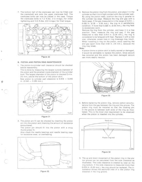
4. Before replacing the piston ring , remove carbon accumulations<br />
from the gap between the ring and the groove. The<br />
piston ring must be installed so that the locating pin<br />
in the groove is between both ends of the ring as illustrated<br />
. This is the most vital requirement to be ob served<br />
when the piston is inserted into the cyltnder.<br />
Nock p in<br />
Piston ring end<br />
Figure 34<br />
TJ34<br />
Figure 32<br />
5. The up and down movement of the piston ring in the piston<br />
groove can be calculated from the sid e clearance as<br />
illustrated. Th is s ide clearance is created by wear on t he<br />
ring bottom . If the side clearance is measured more t han<br />
0.019 in. (0.05 mm.), the ring should be replaced. The illustration<br />
sh ow s the sectional view of a new piston ri ng<br />
installed in the ring groove.


