

1975 Thunderjet - Vintage Snow
1975 Thunderjet - Vintage Snow
1975 Thunderjet - Vintage Snow

Create successful ePaper yourself
Turn your PDF publications into a flip-book with our unique Google optimized e-Paper software.
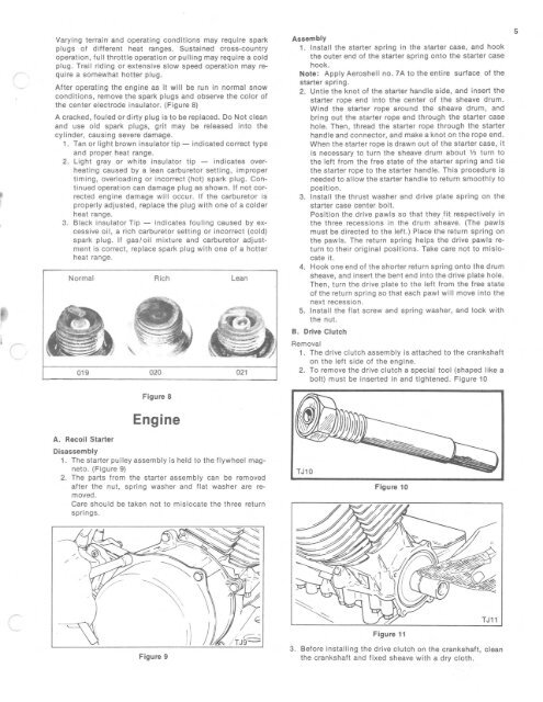
Varying terrain and operating conditions may require spark<br />
plugs of different heat ranges. Sustained cro ss-country<br />
operation, full throttle operation or pulling may require a cold<br />
plug. Tra il riding or extensive slow speed operation may require<br />
a somewhat hotter plug .<br />
After operating the engine as it will be run in normal snow<br />
conditions, remove the spark plugs and observe the color of<br />
the center electrode in sul ator. (Figure 8)<br />
A cracked, fouled or dirty plug is to be replaced . Do Not clean<br />
and use old spark plugs, grit may be released into the<br />
cyl inder, causing severe dam age.<br />
1. Tan or light brown in sulator tip - ind icated correct type<br />
and proper heat range.<br />
2. Light gray or white insulator tip - indicates overheat<br />
ing caused by a lean carburetor setting, improper<br />
timing, overloading or incorrect (hot) spark plug. Con <br />
tinued operation can damage plug as shown. If not corrected<br />
engine damage will occur. If the carburetor is<br />
properly adjusted, replace the plug with one of a colder<br />
heat range .<br />
3. Black insulator Tip - indicates fouling caused by excessive<br />
oi l, a rich carburetor setting or incorrect (cold)<br />
spark plug. If gasloil m ixture and carburetor adjustment<br />
is correct, replace spark plug with one of a hotter<br />
heat range.<br />
Normal<br />
019<br />
A. Recoil Sta rte r<br />
Ric h<br />
020<br />
Fi gure 8<br />
Engine<br />
Lean<br />
021<br />
Disassembly<br />
1. The starter pulley assem bly is held to t he flywheel magneto.<br />
(Fi gure 9)<br />
2. The parts from the starter assembly can be removed<br />
after the nut, spring washer and flat washer are removed.<br />
Care should be taken not to m islocate the three return<br />
springs.<br />
Assembly<br />
1. Install the starter spring in the st arter case , and hook<br />
the outer end of the st arter spring onto the sta rte r case<br />
hook .<br />
Not e: A pp ly Aero shell no . 7A to th e entire surface of t he<br />
starte r spring.<br />
2. Untie the knot of the starter handle side , and in sert the<br />
start er rope end into th e center of the sheave drum.<br />
Wind the starter rope around th e sheave drum, and<br />
bring out the starter rope end through th e st arter case<br />
hole. Then , thread the starter rope through th e starter<br />
handle and connector, and make a knot on the rope end.<br />
When the starter rope is drawn out of the starter case, it<br />
is necessary to t urn th e sheave drum about 1/3 turn to<br />
th e left from the free state of the st arter spring and tie<br />
the starter rope to the starter handle. This procedure is<br />
needed to allow the starter handle to return smoot hly to<br />
position.<br />
3. Install the thrust wa sher and dr ive plat e spring on the<br />
starter case center bolt.<br />
Position the drive pawls so that they fit respectively in<br />
the three recessions in the drum sheave. (The paw ls<br />
mu st be directed to the left.) Place t he return spring on<br />
th e pawls. The return spring helps th e drive pawl s return<br />
to their original positions. Take care not to mislocate<br />
it.<br />
4. Hook one end of t he shorter return spring onto the drum<br />
sheave , and insert the bent end into the drive plate hole.<br />
Then , turn the dr ive plate to the left from the free state<br />
of the return spring so that each paw l w ill move into the<br />
next recession.<br />
5. Install the fla t screw and spring washer, and lock with<br />
the nut.<br />
B. Drive Clutch<br />
Removal<br />
1. The drive clutch assembly is attached to the crankshaft<br />
on the left side of the engine.<br />
2. To remove the drive clutch a special to ol (shaped like a<br />
bo lt) must be inserted in and tightened. Figure 10<br />
Fi gure 10<br />
5<br />
Fig ure 9<br />
Figu re 11<br />
3. Befo re installing the drive clutch on the cranks haft, clean<br />
th e crankshaft and fixed she ave with a d ry clo th.


