

1975 Thunderjet - Vintage Snow
1975 Thunderjet - Vintage Snow
1975 Thunderjet - Vintage Snow

Create successful ePaper yourself
Turn your PDF publications into a flip-book with our unique Google optimized e-Paper software.
8<br />
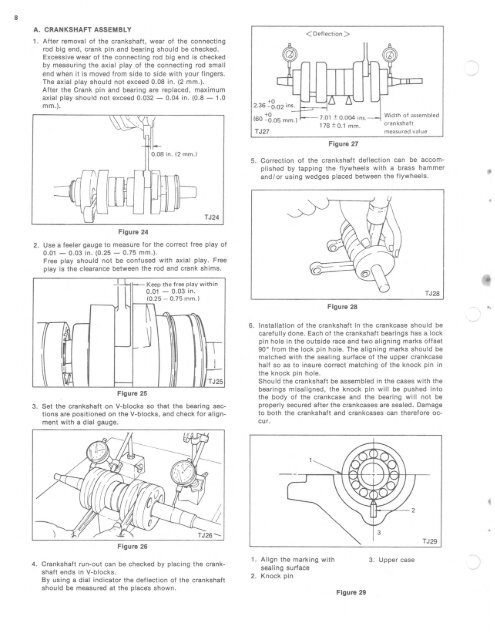
A. CRANKSHAFT ASSEMBLY<br />
1. After removal of the crankshaft, wear of t he connecting<br />
rod big end , crank pin and bear ing should be checked.<br />
Excessive wear of the connecting rod big end is checked<br />
by m,easuring the ax ial play of the connecting rod small<br />
end when it is moved from side to side with your f ingers.<br />
The axia l play should not exceed 0.08 in. (2 mm.).<br />
After the Crank pin and bearing are replaced, maximum<br />
axial play should not exceed 0.032 - 0.04 in. (0.8 - 1.0<br />
mm.).<br />
+0<br />
2.36 - 0.0 2 ins.<br />
+0<br />
(60 - 0.0 5 rnrn.]<br />
TJ27<br />
< Deflection ><br />
7.0 1 ± 0.004 i ns.<br />
178 ± 0. 1 mm.<br />
Width o f assem bled<br />
cran kshaf t<br />
measu red value<br />
Figure 27<br />
0.08 in. (2 mm.)<br />
5. Correction of the crankshaft deflection can be accomplished<br />
by tapping the flywheels w ith a brass hammer<br />
and/or using wedges placed between the flywheels.<br />
,<br />
TJ24<br />
Figure 24<br />
2. Use a feeler gauge to measure for the correct free play of<br />
0.01 - 0.03 in. (0.25 - 0.75 mm .).<br />
Free play should not be confused with axial play. Free<br />
play is the clearance between the rod and crank shims.<br />
I<br />
rr<br />
~<br />
~~<br />
,<br />
I<br />
Keep the free play within<br />
0.01 - 0.03 in .<br />
(0.25 - 0.75 mm.]<br />
~l ~ -<br />
j<br />
1 ,1<br />
T<br />
I J-<br />
~ - TJ25<br />
Figure 25<br />
3. Set the crank shaft on V-blocks so that the bearing sections<br />
are positioned on th e V-blocks, and check for alignment<br />
with a dial gauge.<br />
Figure 28<br />
TJ28<br />
6. Installation of the crankshaft in the crankcase should be<br />
carefully done. Each of the crankshaft bear ings has a lock<br />
pin hole in the outside race and two aligning marks offset<br />
90° from the lock pin hole. The aligning marks should be<br />
matched with the sealing surface of the upper crankcase<br />
half so as to insure correct matching of the knock pin in<br />
the knock pin hole.<br />
Should the crankshaft be assembled in the cases with the<br />
bearings misaligned, the knock pin will be pushed into<br />
the body of the crankcase and the bearing w ill not be<br />
properly secured after the crankcases are sealed. Damage<br />
to both the crankshaft and crankcases can therefore occur.<br />
Figure 26<br />
TJ29<br />
•<br />
4. Crankshaft run-out can be checked by placing the crankshaft<br />
end s in V-blocks.<br />
By using a dial indicator the deflection of the crankshaft<br />
should be measured at the places shown.<br />
1. Align the marking with 3. Upper case<br />
sealing surface<br />
2. Knock pin<br />
Figure 29


