

1975 Thunderjet - Vintage Snow
1975 Thunderjet - Vintage Snow
1975 Thunderjet - Vintage Snow

Create successful ePaper yourself
Turn your PDF publications into a flip-book with our unique Google optimized e-Paper software.
D. High Speed System<br />
Fue l fr om th e f loat chamber passes through the main jet<br />
and enters the needle jet. Air entering the main air intake<br />
pass es th rou gh the air bleed in the need le jet and m ixes<br />
with the fu el being d ischarged fr om t he needle jet . A ir<br />
ent ering f rom the main bore also mixes w ith the fue l and<br />
t hen enters the engine at the proper air fuel mixture. The<br />
cl earance between the need le jet and the jet needle is<br />
greater than th e metered orifi ce of th e main jet. Therefo<br />
re, the jet need le has no aff ect on the high speed sys <br />
tem. No te : The main jet on ly affects the high speed sys <br />
tem. (From one half to full t hrottle.)<br />
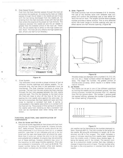
B. Slide Figure 50<br />
The slide controls fuel mixture between 0 & V2 throttle.<br />
The use of the throttle valve with different size cutaways<br />
wi ll control the discharge rate of fu el which affects<br />
t he fue l air ratio. The largest throttle valve cutaway<br />
number provides a lean er m ixture. Thi s is only effective<br />
w ith in the lower range of throttle opening and has no<br />
effect above one half throttle open ing . (Figure 50)<br />
17<br />
Figure 49<br />
TJ49<br />
E. Floa t System<br />
The carbu retor must prov ide a proper mixture of fuel at<br />
different throttle open ings and engine speeds. To accomp<br />
lish this, the fue l level in the carburetor mu st be<br />
ma inta ined. The float cha mbe r functi ons to serve this<br />
purpose. The fuel from t he tan k enters the f loat cha mber<br />
th rou gh th e f uel inlet passage between th e inle t needle<br />
valve and seat. This f ills th e chamber to the level wh ere<br />
the float arm rises to shut off t he fl ow of t he fuel by<br />
seat ing the inl et needl e valve aga ins t the valve seat. As<br />
t he fu el is consumed, the f loat needle wi ll ope n and t hen<br />
close to main tain a constant fuel level. A sp ring is<br />
incorporated in the need le valve wh ich is in co ntact w it h<br />
th e fl oat arm li p. The purpose of this sp ring is to prevent<br />
the needle valve fr om vibra t ing so tha t a co nstan t fu el<br />
level can be mai ntained even when ridi ng over roug h<br />
terrain.<br />
FUNC TION , SelECTION, AND IDENTI FICAT ION OF<br />
COMPONENTS<br />
A. Pilot Air Screw and Pilot Jet<br />
The pil ot air screw regulates air th at mixes w ith fuel from<br />
the pilot jet. Turning pil ot air screw IN, richens mixture,<br />
OUT , leans mixture. The pilot air screw should be normally<br />
positioned V2 to 2 turns out from full in, or seated<br />
position. Les s than V2 turn ind icat es pilot jet to be too<br />
sma ll and the next size larger pilot jet should be used .<br />
More than 2 t urns out, shows the pilot to be too large<br />
and a smaller jet is need ed. An engine may idle smoothly<br />
out of these settings, however problems may occur in<br />
the transition to m id range throttle operation. Pi lot jets<br />
are numbered in increments , of 5, such as 20-25-30 . The<br />
lowest number being the smaller orfice and leanest,<br />
wh ile higher numbers are the richest mixtures.<br />
\<br />
Figure 50<br />
TJ50<br />
Throttle slides are stamped w ith a number (1.5, 2.0, 2.5,<br />
3.0 , 3.5 , etc .) ; these numbers reflect the degree of cutawa<br />
y. The larger t he number, the grea ter portion of<br />
throttle slide cu t-away, which resu lts in a leaner in itial<br />
fue l-air mixtu re.<br />
C. Jet Needle<br />
The need le can be set in one of fi ve d ifferent pos it ions<br />
by mov ing th e need le clip to a different groove. For fine<br />
t uni ng purposes, number th e grooves fr om 1-5, starting<br />
from the top groove down. The num ber 1 groove gives<br />
the leanest setting , whe reas the number 5 groove gives<br />
th e richest sett ing . (Figure ~1 ) .<br />
2 3 4 5<br />
JW=:I===:=======:::><br />
TJ51<br />
Figure 51<br />
Jet needles can be identified by the number stam ped o n<br />
them. Example 60P1-3 . The first number is th e length of<br />
th e needl e, #6 being 60 millimeters in length, #2 is the<br />
shortest and #9 is the lo ngest. The lett er indicates a<br />
scale of richness resulti ng from needle taper measured<br />
from the middle notch, 2 letters show double taper. A ,<br />
being the leanest and Z, the richest. The second number<br />
is a productio n model number that may indicate a<br />
change in beg inning point of taper. The last number after<br />
the dash is the clip po sition in notches from the top of<br />
need le.


