Solid State Relay (SSR) Mounting and Installation - Watlow
Solid State Relay (SSR) Mounting and Installation - Watlow
Solid State Relay (SSR) Mounting and Installation - Watlow

You also want an ePaper? Increase the reach of your titles
YUMPU automatically turns print PDFs into web optimized ePapers that Google loves.
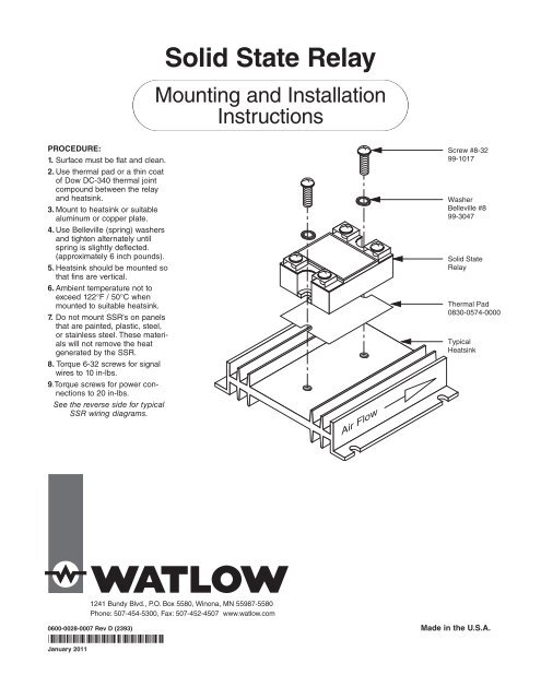
<strong>Solid</strong> <strong>State</strong> <strong>Relay</strong><br />
<strong>Mounting</strong> <strong>and</strong> <strong>Installation</strong><br />
Instructions<br />
PROCEDURE:<br />
1. Surface must be flat <strong>and</strong> clean.<br />
2. Use thermal pad or a thin coat<br />
of Dow DC-340 thermal joint<br />
compound between the relay<br />
<strong>and</strong> heatsink.<br />
3. Mount to heatsink or suitable<br />
aluminum or copper plate.<br />
4. Use Belleville (spring) washers<br />
<strong>and</strong> tighten alternately until<br />
spring is slightly deflected.<br />
(approximately 6 inch pounds).<br />
5. Heatsink should be mounted so<br />
that fins are vertical.<br />
6. Ambient temperature not to<br />
exceed 122°F / 50°C when<br />
mounted to suitable heatsink.<br />
7. Do not mount <strong>SSR</strong>'s on panels<br />
that are painted, plastic, steel,<br />
or stainless steel. These materials<br />
will not remove the heat<br />
generated by the <strong>SSR</strong>.<br />
8. Torque 6-32 screws for signal<br />
wires to 10 in-lbs.<br />
9.Torque screws for power connections<br />
to 20 in-lbs.<br />
See the reverse side for typical<br />
<strong>SSR</strong> wiring diagrams.<br />
Air Flow<br />
Screw #8-32<br />
99-1017<br />
Washer<br />
Belleville #8<br />
99-3047<br />
<strong>Solid</strong> <strong>State</strong><br />
<strong>Relay</strong><br />
Thermal Pad<br />
0830-0574-0000<br />
Typical<br />
Heatsink<br />
1241 Bundy Blvd., P.O. Box 5580, Winona, MN 55987-5580<br />
Phone: 507-454-5300, Fax: 507-452-4507 www.watlow.com<br />
0600-0028-0007 Rev D (2393) Made in the U.S.A.<br />
January 2011
L2<br />
L1<br />
ç<br />
DC or AC Input <strong>Solid</strong> <strong>State</strong> <strong>Relay</strong> Wiring Diagram<br />
2<br />
Semiconductor<br />
Fuse<br />
Limit Control<br />
1<br />
Contacts<br />
(If Required)<br />
3-32VDC<br />
DC Input<br />
OR<br />
90-240VAC<br />
AC Input<br />
(-)<br />
(+)<br />
Heater<br />
DC Input, DC Output <strong>Solid</strong> <strong>State</strong> <strong>Relay</strong> Wiring Diagram<br />
1<br />
ç<br />
External<br />
DC Power<br />
Supply<br />
0-100 VDC<br />
Open Collector<br />
DC Input, 3-32VDC<br />
ç<br />
Limit Control<br />
Contacts<br />
(If Required)<br />
(-)<br />
(+)<br />
Heater<br />
Install diode if<br />
load is inductive<br />
<strong>SSR</strong>-100-20A-DC1<br />
Fuse<br />
1 2<br />
4 3<br />
1(–) (+)2<br />
4(–) (+)3<br />
ç 1<br />
WARNING:<br />
Wiring must conform<br />
to National<br />
Electric Code<br />
(NEC) safety st<strong>and</strong>ards,<br />
as well as<br />
locally applicable<br />
codes. Failure to<br />
do so could<br />
result in personal<br />
injury or death.<br />
ç 2<br />
WARNING:<br />
Wiring examples<br />
show L2 in<br />
240VAC or<br />
480VAC configuration.<br />
In 120VAC<br />
applications, L2 is<br />
neutral <strong>and</strong> must<br />
not be fused or<br />
switched. Failure<br />
to follow this<br />
guideline could<br />
result in personal<br />
injury or death.<br />
3 Phase, 2 leg <strong>Solid</strong> <strong>State</strong> <strong>Relay</strong> Wiring Diagram<br />
L3<br />
L2<br />
L1<br />
ç<br />
ç<br />
2<br />
Semiconductor<br />
Fuses Limit Control<br />
1<br />
Contacts<br />
(If Required)<br />
3 Phase<br />
Heater<br />
1 2<br />
4 3<br />
1 2<br />
4 3<br />
Control Input Signal<br />
<strong>SSR</strong> <strong>Mounting</strong> <strong>and</strong> <strong>Installation</strong> Instructions