![[MI 019-100] Universal Instruction Manual I/A Series Mass Flow ...](https://img.yumpu.com/34296656/29/500x640/mi-019-100-universal-instruction-manual-i-a-series-mass-flow-.jpg)
[MI 019-100] Universal Instruction Manual I/A Series Mass Flow ...
[MI 019-100] Universal Instruction Manual I/A Series Mass Flow ...
[MI 019-100] Universal Instruction Manual I/A Series Mass Flow ...

Create successful ePaper yourself
Turn your PDF publications into a flip-book with our unique Google optimized e-Paper software.
2. Installation <strong>MI</strong> <strong>019</strong>-<strong>100</strong> – December 2003<br />
Output<br />
Signal<br />
Code<br />
Terminal<br />
5<br />
Table 7. Input/Output Wiring Connections<br />
Terminal<br />
6<br />
Terminal<br />
4<br />
Terminal<br />
4.1<br />
Terminal<br />
4.2<br />
1<br />
Contact Input Pulse Output Contact Output<br />
2 Contact Input Current Output 2 Contact Output<br />
C<br />
Current<br />
Current Output 2 Contact Input Pulse Output<br />
Common Output<br />
D<br />
1<br />
Current Output 2 Current Output 3 Pulse Output<br />
E<br />
Current Output 2 Current Output 3 Contact Input<br />
F<br />
Current Output 2 Current Output 3 Contact Output<br />
NOTE<br />
The CFT50 Transmitter output circuits are externally powered. The most common<br />
power supply voltage is 24 V dc.<br />
Current Outputs<br />
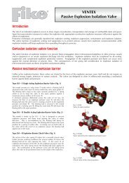
A wiring diagram for a Current Output is shown in Figure 10.<br />
POSITIVE POWER INPUT<br />
TER<strong>MI</strong>NAL (5)<br />
+ –<br />
24 V DC<br />
CURRENT OUTPUT<br />
TER<strong>MI</strong>NAL (6, 4, OR 4.1)<br />
LOOP<br />
+<br />
LOAD* –<br />
*FOR EXAMPLE, AI MODULE<br />
Figure 10. Current Output<br />
The loop load vs voltage relationship is:<br />
R MAX = (V-10)/0.0205.<br />
A minimum of 10 V must be maintained across the transmitter terminals for proper operation.<br />
To determine the maximum loop load resistance, add the series resistance of each component in<br />
the loop, excluding the transmitter.<br />
Figure 11 shows the output load vs voltage relationship from 10 to 24 volts.<br />
19