![[MI 019-100] Universal Instruction Manual I/A Series Mass Flow ...](https://img.yumpu.com/34296656/31/500x640/mi-019-100-universal-instruction-manual-i-a-series-mass-flow-.jpg)
[MI 019-100] Universal Instruction Manual I/A Series Mass Flow ...
[MI 019-100] Universal Instruction Manual I/A Series Mass Flow ...
[MI 019-100] Universal Instruction Manual I/A Series Mass Flow ...

Create successful ePaper yourself
Turn your PDF publications into a flip-book with our unique Google optimized e-Paper software.
2. Installation <strong>MI</strong> <strong>019</strong>-<strong>100</strong> – December 2003<br />
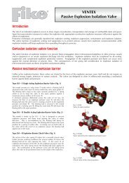
A wiring diagram for a Contact Output is shown in Figure 13.<br />
POSITIVE POWER INPUT<br />
TER<strong>MI</strong>NAL (5)<br />
+ –<br />
24 V dc<br />
CONTACT OUTPUT<br />
TER<strong>MI</strong>NAL (4.2)<br />
+<br />
LOAD*<br />
–<br />
*For example, lamp, relay, coil<br />
Figure 13. Contact Output<br />
The voltage requirement for contact output is 24 V dc ±10%. The load requirement is governed<br />
by producing a maximum current of <strong>100</strong> mA.<br />
Pulse Output<br />
A wiring diagram for a Pulse Output is shown in Figure 14.<br />
POSITIVE POWER INPUT<br />
TER<strong>MI</strong>NAL (5)<br />
+ –<br />
24 V dc<br />
PULSE OUTPUT<br />
TER<strong>MI</strong>NAL (4.1 OR 4.2)<br />
+ –<br />
RECEIVER*<br />
*For example, Model 75 Totalizer<br />
300 Ω<br />
Figure 14. Pulse Output<br />
The maximum pulse current is 80 mA. This requires a minimum 300 Ω pulse load resistor. In<br />
connecting your pulse loop, always place the pulse load resistor at the receiver.<br />
Higher pulse output frequencies require a minimum load.<br />
Sometimes a resistor divider is required because of the bias current of the receiver input. Refer to<br />
Figure 15. In such cases, the bias current times R2 must be less than the maximum low input<br />
threshold of the receiver.<br />
21