

Journal of Reliable Power - SEL
Journal of Reliable Power - SEL
Journal of Reliable Power - SEL

Create successful ePaper yourself
Turn your PDF publications into a flip-book with our unique Google optimized e-Paper software.
As a way <strong>of</strong> confirming that the data was correct, we ran<br />
the two-ended negative-sequence impedance algorithm using<br />
the event reports from each end, as shown in Figure 12.<br />
A<br />
A-B-G<br />
-143.2 mi<br />
Reported<br />
6.8 mi from A<br />
Actual<br />
No event<br />
available<br />
B<br />
1.8<br />
115-Line 48.4 mi<br />
1.5<br />
m v<br />
ms v<br />
.633<br />
1<br />
0.5<br />
Calculated<br />
Two-Ended FL<br />
Actual FL<br />
0.1<br />
0 2 4 6 8<br />
0 v<br />
8<br />
RS<br />
Figure 12 Example 1: Mathcad Screen Capture—Actual Fault Location vs.<br />
Two-Ended Estimate<br />
The actual fault occurred where the sprinkler system was<br />
found, between 17.8 and 17.9 miles (m = .633) from<br />
Terminal G (based on patrol map tower locations).<br />
Conclusions for Example 1:<br />
1. The one-ended (17.28 and 10.00 miles, respectively)<br />
and two-ended (17.46 miles) fault locations yielded<br />
good results. All fault location estimates were within<br />
2%.<br />
2. Two-ended negative-sequence impedance-based<br />
method corroborates one-ended method.<br />
B. Example 2: Incorrect Fault Location Due to Incorrect<br />
Fault Type Identified<br />
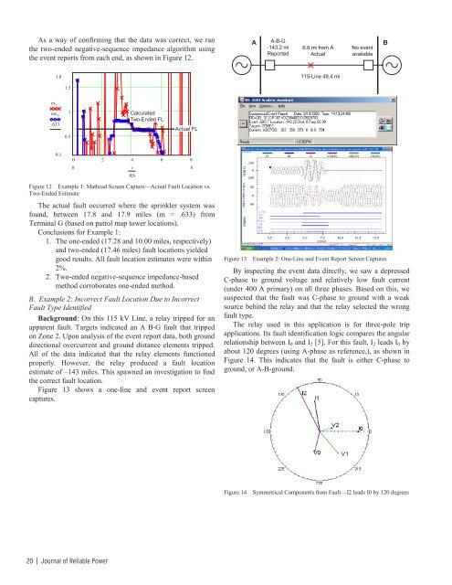
Background: On this 115 kV Line, a relay tripped for an<br />
apparent fault. Targets indicated an A B-G fault that tripped<br />
on Zone 2. Upon analysis <strong>of</strong> the event report data, both ground<br />
directional overcurrent and ground distance elements tripped.<br />
All <strong>of</strong> the data indicated that the relay elements functioned<br />
properly. However, the relay produced a fault location<br />
estimate <strong>of</strong> –143 miles. This spawned an investigation to find<br />
the correct fault location.<br />
Figure 13 shows a one-line and event report screen<br />
captures.<br />
Figure 13<br />
Example 2: One-Line and Event Report Screen Captures<br />
By inspecting the event data directly, we saw a depressed<br />
C-phase to ground voltage and relatively low fault current<br />
(under 400 A primary) on all three phases. Based on this, we<br />
suspected that the fault was C-phase to ground with a weak<br />
source behind the relay and that the relay selected the wrong<br />
fault type.<br />
The relay used in this application is for three-pole trip<br />
applications. Its fault identification logic compares the angular<br />
relationship between I 0 and I 2 [5]. For this fault, I 2 leads I 0 by<br />
about 120 degrees (using A-phase as reference,), as shown in<br />
Figure 14. This indicates that the fault is either C-phase to<br />
ground, or A-B-ground.<br />
Figure 14<br />
Symmetrical Components from Fault—I2 leads I0 by 120 degrees<br />
20 | <strong>Journal</strong> <strong>of</strong> <strong>Reliable</strong> <strong>Power</strong>


