

Journal of Reliable Power - SEL
Journal of Reliable Power - SEL
Journal of Reliable Power - SEL

Create successful ePaper yourself
Turn your PDF publications into a flip-book with our unique Google optimized e-Paper software.
12<br />
The prefault data from the backup relay are shown in<br />
Fig. 32, and the prefault data from the primary relay are<br />
shown in Fig. 33. The phase voltages seen by the primary<br />
relay in the prefault state did not look normal or balanced, and<br />
a significant standing zero-sequence voltage was present. The<br />
backup relay, on the contrary, reported normal prefault<br />
voltages.<br />
180<br />
135<br />
225<br />
135<br />
90<br />
VC (kV)<br />
IB<br />
IA<br />
VB (kV)<br />
270<br />
90<br />
IC<br />
45<br />
VA (kV)<br />
0<br />
315<br />
45<br />
The neutral bus <strong>of</strong> the primary relay three-phase voltage<br />
connections should have been connected at a terminal block to<br />
station ground; this wire was missing. The result was that the<br />
primary relay voltages were floating, and this distorted phaseto-neutral<br />
magnitudes, angles, and sequence components both<br />
before the fault and during the fault. The backup relay had<br />
properly terminated voltages and, therefore, its zero-sequence<br />
voltage polarized directional element performed correctly.<br />
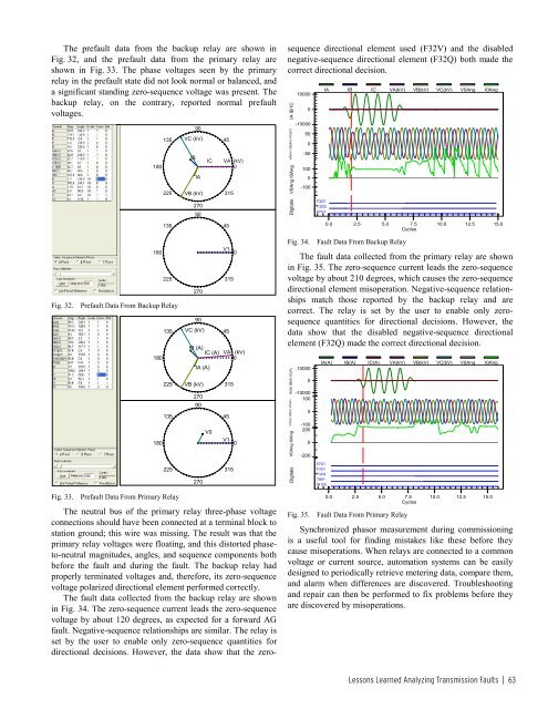
The fault data collected from the backup relay are shown<br />
in Fig. 34. The zero-sequence current leads the zero-sequence<br />
voltage by about 120 degrees, as expected for a forward AG<br />
fault. Negative-sequence relationships are similar. The relay is<br />
set by the user to enable only zero-sequence quantities for<br />
directional decisions. However, the data show that the zerosequence<br />
directional element used (F32V) and the disabled<br />
negative-sequence directional element (F32Q) both made the<br />
correct directional decision.<br />
IA IB IC<br />
VA(kV) VB(kV) VC(kV)<br />
V0Ang I0Ang<br />
Digitals<br />
10000<br />
0<br />
-10000<br />
50<br />
0<br />
-50<br />
100<br />
0<br />
-100<br />
F32V<br />
F32Q<br />
67G1<br />
IA IB IC VA(kV) VB(kV) VC(kV) V0Ang I0Ang<br />
0.0 2.5 5.0 7.5 10.0 12.5 15.0<br />
Cycles<br />
Fig. 32.<br />
180<br />
225<br />
Prefault Data From Backup Relay<br />
135<br />
180<br />
225<br />
135<br />
180<br />
270<br />
90<br />
VC (kV)<br />
IB (A)<br />
IC (A)<br />
IA (A)<br />
VB (kV)<br />
270<br />
90<br />
V0<br />
V1<br />
0<br />
315<br />
45<br />
VA (kV)<br />
0<br />
315<br />
45<br />
V1<br />
0<br />
Fig. 34.<br />
Fault Data From Backup Relay<br />
The fault data collected from the primary relay are shown<br />
in Fig. 35. The zero-sequence current leads the zero-sequence<br />
voltage by about 210 degrees, which causes the zero-sequence<br />
directional element misoperation. Negative-sequence relationships<br />
match those reported by the backup relay and are<br />
correct. The relay is set by the user to enable only zerosequence<br />
quantities for directional decisions. However, the<br />
data show that the disabled negative-sequence directional<br />
element (F32Q) made the correct directional decision.<br />
IA(A) IB(A) IC(A)<br />
VA(kV) VB(kV) VC(kV)<br />
V0Ang I0Ang<br />
10000<br />
0<br />
-10000<br />
100<br />
0<br />
-100<br />
200<br />
0<br />
-200<br />
IA(A) IB(A) IC(A) VA(kV) VB(kV) VC(kV) V0Ang I0Ang<br />
225<br />
270<br />
315<br />
Digitals<br />
67G1<br />
F32V<br />
F32Q<br />
TRIP<br />
IN105<br />
Fig. 33.<br />
Prefault Data From Primary Relay<br />
Fig. 35.<br />
0.0 2.5 5.0 7.5 10.0 12.5 15.0<br />
Cycles<br />
Fault Data From Primary Relay<br />
Synchronized phasor measurement during commissioning<br />
is a useful tool for finding mistakes like these before they<br />
cause misoperations. When relays are connected to a common<br />
voltage or current source, automation systems can be easily<br />
designed to periodically retrieve metering data, compare them,<br />
and alarm when differences are discovered. Troubleshooting<br />
and repair can then be performed to fix problems before they<br />
are discovered by misoperations.<br />
Lessons Learned Analyzing Transmission Faults | 63


