

Journal of Reliable Power - SEL
Journal of Reliable Power - SEL
Journal of Reliable Power - SEL

You also want an ePaper? Increase the reach of your titles
YUMPU automatically turns print PDFs into web optimized ePapers that Google loves.
8<br />
1_VA 1_VB 1_VC<br />
2_VA 2_VB 2_VC<br />
3_VA(kV) 3_VB(kV) 3_VC(kV)<br />
25<br />
0<br />
-25<br />
0<br />
-50<br />
25<br />
0<br />
-25<br />
1_VA 1_VB 1_VC 2_VA 2_VB<br />
2_VC 3_VA(kV) 3_VB(kV) 3_VC(kV)<br />
.020833 sec<br />
Digitals<br />
3_LOP<br />
2_OUT TP *<br />
2_LOP * *<br />
2_IN 52A *<br />
L<br />
2_50P<br />
2_21P 1<br />
1_ZBC 4 2<br />
1_OUT 1&2 1<br />
1_LOP * *<br />
1_IN 1&2 B 2<br />
1_50P<br />
L<br />
1_32 Q Q<br />
50.50 50.55 50.60 50.65 50.70 50.75<br />
Event Time (Sec) 23:31:50.588677<br />
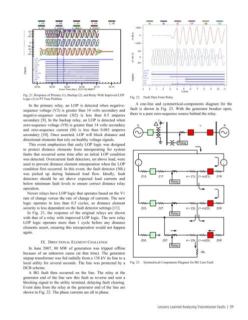
Fig. 21. Response <strong>of</strong> Primary (1), Backup (2), and Relay With Improved LOP<br />
Logic (3) to PT Fuse Problem<br />
In the primary relay, an LOP is detected when negativesequence<br />
voltage (V2) is greater than 14 volts secondary and<br />
negative-sequence current (3I2) is less than 0.5 amperes<br />
secondary [9]. In the backup relay, an LOP is detected when<br />
zero-sequence voltage (V0) is greater than 14 volts secondary<br />
and zero-sequence current (I0) is less than 0.083 amperes<br />
secondary [10]. Once asserted, LOP will block distance and<br />
directional elements that rely on healthy voltage signals.<br />
This event emphasizes that early LOP logic was designed<br />
to protect distance elements from misoperating for system<br />
faults that occurred some time after an initial LOP condition<br />
was detected. Overcurrent fault detectors, set above load, were<br />
used to prevent distance element misoperation when the LOP<br />
condition first occurred. In this event, the fault detector (50L)<br />
was picked up during balanced load flow. Ideally, fault<br />
detectors should be set above expected load currents and<br />
below minimum fault levels to ensure correct distance relay<br />
operation.<br />
Newer relays have LOP logic that operates based on the V1<br />
rate <strong>of</strong> change versus the rate <strong>of</strong> change <strong>of</strong> currents. The new<br />
logic operates in less than 0.5 cycles, so distance element<br />
security is less dependent on the fault detector settings [11].<br />
In Fig. 21, the response <strong>of</strong> the original relays are shown<br />
with that <strong>of</strong> a relay with improved LOP logic. The new relay<br />
LOP logic operates more than 1 cycle before any distance<br />
elements assert, ensuring this misoperation would not happen<br />
again.<br />
IX. DIRECTIONAL ELEMENT CHALLENGE<br />
In June 2007, 80 MW <strong>of</strong> generation was tripped <strong>of</strong>fline<br />
because <strong>of</strong> an unknown cause (at that time). The generator<br />
stepup transformer was fed radially from a 138 kV tie line to a<br />
local utility for several seconds. The line was protected by a<br />
DCB scheme.<br />
A BG fault then occurred on the line. The relay at the<br />
generator end <strong>of</strong> the line saw this fault as reverse and sent a<br />
blocking signal to the utility terminal, delaying fault clearing.<br />
Event data from the relay at the generator end <strong>of</strong> the line are<br />
shown in Fig. 22. The phase currents are all in phase.<br />
Fig. 22.<br />
Fault Data From Relay<br />
A one-line and symmetrical-components diagram for the<br />
fault is shown in Fig. 23. With the generator breaker open,<br />
there is a pure zero-sequence source behind the relay.<br />
S<br />
–<br />
+<br />
Fig. 23.<br />
T<br />
Relay<br />
Z1S Z1T m • Z1L (1–m)Z1L Z1R<br />
Relay<br />
Z2S Z2T m • Z2L (1–m)Z2L Z2R<br />
Relay<br />
Z0S Z0T m • Z0L (1–m)Z0L Z0R<br />
Relay<br />
L<br />
3R F<br />
Symmetrical Components Diagram for BG Line Fault<br />
R<br />
–<br />
+<br />
Lessons Learned Analyzing Transmission Faults | 59


