

Journal of Reliable Power - SEL
Journal of Reliable Power - SEL
Journal of Reliable Power - SEL

You also want an ePaper? Increase the reach of your titles
YUMPU automatically turns print PDFs into web optimized ePapers that Google loves.
element misoperation. Shunt reactor switching generates<br />
damped oscillations with signals that have frequencies<br />
different from the actual system frequency. Let us look at an<br />
example <strong>of</strong> these signals and the logic that prevents the<br />
memory polarization from using unhealthy voltages.<br />
A. Shunt Reactor Switching<br />
Shunt reactors compensate the line charging currents and<br />
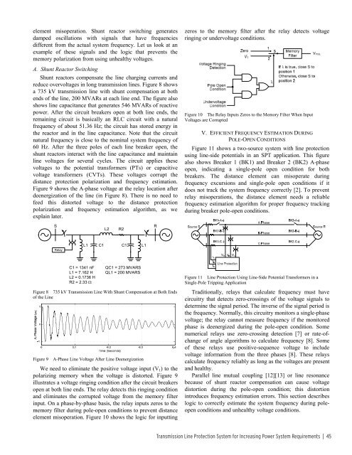
reduce overvoltages in long transmission lines. Figure 8 shows<br />
a 735 kV transmission line with shunt compensation at both<br />
ends <strong>of</strong> the line, 200 MVARs at each line end. The figure also<br />
shows line capacitance that generates 546 MVARs <strong>of</strong> reactive<br />
power. After the circuit breakers open at both line ends, the<br />
remaining circuit is basically an RLC circuit with a natural<br />
frequency <strong>of</strong> about 51.36 Hz; the circuit has stored energy in<br />
the reactor and in the line capacitance. Note that the circuit<br />
natural frequency is close to the nominal system frequency <strong>of</strong><br />
60 Hz. After the three poles <strong>of</strong> each line breaker open, the<br />
shunt reactors interact with the line capacitance and maintain<br />
line voltages for several cycles. The circuit applies these<br />
voltages to the potential transformers (PTs) or capacitive<br />
voltage transformers (CVTs). These voltages corrupt the<br />
distance protection polarization and frequency estimation.<br />
Figure 9 shows the A-phase voltage at the relay location after<br />
deenergization <strong>of</strong> the line (in Figure 8). There is no need to<br />
feed this distorted voltage to the distance protection<br />
polarization and frequency estimation algorithm, as we<br />
explain later.<br />
zeros to the memory filter after the relay detects voltage<br />
ringing or undervoltage conditions.<br />
Figure 10 The Relay Inputs Zeros to the Memory Filter When Input<br />
Voltages are Corrupted<br />
V. EFFICIENT FREQUENCY ESTIMATION DURING<br />
POLE-OPEN CONDITIONS<br />
Figure 11 shows a two-source system with line protection<br />
using line-side potentials in an SPT application. This figure<br />
also shows Breaker 1 (BK1) and Breaker 2 (BK2) A-phase<br />
open, indicating a single-pole open condition for both<br />
breakers. The distance element can misoperate during<br />
frequency excursions and single-pole open conditions if it<br />
does not track the system frequency correctly [2]. To prevent<br />
relay misoperations, the distance element needs a reliable<br />
frequency estimation algorithm for proper frequency tracking<br />
during breaker pole-open conditions.<br />
S<br />
L2<br />
R2<br />
R<br />
Relay<br />
L1<br />
C1<br />
C1<br />
L1<br />
C1 = 1341 nF<br />
L1 = 7.162 H<br />
L2 = 0.1736 H<br />
R2 = 2.33 Ω<br />
QC1 = 273 MVARS<br />
QL1 = 200 MVARS<br />
Figure 8 735 kV Transmission Line With Shunt Compensation at Both Ends<br />
<strong>of</strong> the Line<br />
Figure 9<br />
A-Phase Line Voltage After Line Deenergization<br />
We need to eliminate the positive voltage input (V 1 ) to the<br />
polarizing memory when the voltage is distorted. Figure 9<br />
illustrates a voltage ringing condition after the circuit breakers<br />
open at both line ends. The relay detects this ringing condition<br />
and eliminates the corrupted voltage from the memory filter<br />
input. On a phase-by-phase basis, the relay inputs zeros to the<br />
memory filter during pole-open conditions to prevent distance<br />
element misoperation. Figure 10 shows the logic for inputting<br />
Figure 11 Line Protection Using Line-Side Potential Transformers in a<br />
Single-Pole Tripping Application<br />
Traditionally, relays that calculate frequency must have<br />
circuitry that detects zero-crossings <strong>of</strong> the voltage signals to<br />
determine the signal period. The inverse <strong>of</strong> the signal period is<br />
the frequency. Normally, this circuitry monitors a single-phase<br />
voltage; the relay cannot measure frequency if the monitored<br />
phase is deenergized during the pole-open condition. Some<br />
numerical relays use zero-crossing detection [7] or rate-<strong>of</strong>change<br />
<strong>of</strong> angle algorithms to calculate frequency [8]. Some<br />
<strong>of</strong> these relays use positive-sequence voltage to include<br />
voltage information from the three phases [8]. These relays<br />
calculate frequency reliably as long as the voltages are present<br />
and healthy.<br />
Parallel line mutual coupling [12][13] or line resonance<br />
because <strong>of</strong> shunt reactor compensation can cause voltage<br />
distortion during the pole-open condition; this distortion<br />
introduces frequency estimation errors. This section describes<br />
logic to correctly estimate the system frequency during poleopen<br />
conditions and unhealthy voltage conditions.<br />
Transmission Line Protection System for Increasing <strong>Power</strong> System Requirements | 45


