

Journal of Reliable Power - SEL
Journal of Reliable Power - SEL
Journal of Reliable Power - SEL

You also want an ePaper? Increase the reach of your titles
YUMPU automatically turns print PDFs into web optimized ePapers that Google loves.
Figure 5 illustrates a transmission line with a 50 percent<br />
series-compensated system (e.g., the series capacitor reactance<br />
equals 50 percent <strong>of</strong> the positive-sequence line reactance). For<br />
the fault location shown, the underreaching distance element<br />
at the remote terminal (Station S) should not operate.<br />
Intuitively, we would expect that setting the reach to<br />
80 percent <strong>of</strong> the compensated impedance (Z L1 – jX C ) would<br />
be an appropriate reach setting. However, the series capacitor<br />
and the system inductance generate subharmonic oscillations<br />
that can cause severe overreach <strong>of</strong> the distance element.<br />
Figure 6 shows the impedance plane plot for the fault location<br />
shown in Figure 5 (where the series capacitor remains in<br />
service).<br />
S<br />
Relay<br />
Figure 5 System With Series Capacitors at One End With a Fault at the End<br />
<strong>of</strong> the Line<br />
R<br />
Ignoring variables such as mutual coupling and fault<br />
resistance, we can see that the calculated voltage equals the<br />
measured voltage. Determining the ratio <strong>of</strong> the measured<br />
voltage to the calculated voltage would result in unity or one.<br />
When the fault moves to the other side <strong>of</strong> the series<br />
capacitor (line-side), the measured voltage increases and the<br />
calculated voltage decreases. The measured voltage increases<br />
because the series capacitor is no longer between the relay and<br />
the fault, and the line appears to be electrically longer. The<br />
calculated voltage decreases because the calculated voltage<br />
always includes the series capacitor. The ratio <strong>of</strong> the measured<br />
voltage to the calculated voltage is greater than one for a fault<br />
at this location.<br />
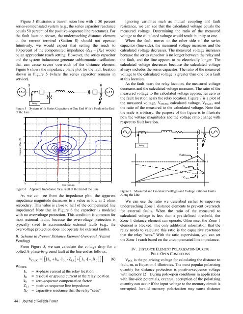
As the fault nears the relay location, the measured voltage<br />
decreases and the calculated voltage increases. The ratio <strong>of</strong> the<br />
measured voltage to the calculated voltage approaches zero as<br />
the fault location nears the relay location. Figure 7 is a plot <strong>of</strong><br />
the measured voltage, V MEAS , calculated voltage, V CALC , and<br />
the ratio <strong>of</strong> the measured to the calculated voltage. Note that<br />
the scale is arbitrary; the purpose <strong>of</strong> this figure is to illustrate<br />
how the voltage magnitudes and the voltage ratio change with<br />
respect to fault location.<br />
Imaginary (Sec. )<br />
Relay<br />
Ratio<br />
1<br />
V MEAS<br />
V CALC<br />
Figure 6<br />
Apparent Impedance for a Fault at the End <strong>of</strong> the Line<br />
As we can see from the impedance plot, the apparent<br />
impedance magnitude decreases to a value as low as 2 ohms<br />
secondary. This value is close to half <strong>of</strong> the compensated line<br />
impedance! Note that in Figure 6 the capacitor is modeled<br />
with no overvoltage protection. This condition is common for<br />
most external faults, because the overvoltage protection is<br />
typically sized to accommodate external faults (e.g., the<br />
overvoltage protection does not operate for external faults).<br />
B. Scheme to Prevent Distance Element Overreach (Patent<br />
Pending)<br />
From Figure 5, we can calculate the voltage drop for a<br />
bolted A-phase-to-ground fault at the line end as follows:<br />
( ) ( )<br />
VCALC = ⎣⎡ IA + k0 ⋅ IG ⋅ ZL1 ⎤⎦ + ⎡⎣ IA ⋅ − jXC<br />
⎤⎦ (6)<br />
Where:<br />
I A = A-phase current at the relay location<br />
I G = residual or ground current at the relay location<br />
k 0 = zero-sequence compensation factor<br />
Z L1 = positive-sequence line impedance<br />
X C = capacitive reactance that the relay “sees”<br />
Figure 7 Measured and Calculated Voltages and Voltage Ratio for Faults<br />
Along the Line<br />
We can use the ratio we described earlier to supervise<br />
underreaching Zone 1 distance elements to prevent overreach<br />
for external faults. When the ratio <strong>of</strong> the measured to<br />
calculated voltage is less than a pre-defined threshold, the<br />
Zone 1 distance element can operate. Otherwise, the Zone 1<br />
element is blocked. The only additional information that the<br />
relay needs to calculate this ratio is the capacitive reactance<br />
that the relay “sees.” With the ratio supervision, you can set<br />
the Zone 1 reach based on the uncompensated line impedance.<br />
IV. DISTANCE ELEMENT POLARIZATION DURING<br />
POLE-OPEN CONDITIONS<br />
V POL is the polarizing voltage for calculating the distance to<br />
fault, m, as Equation 4 illustrates. The most popular polarizing<br />
quantity for distance protection is positive-sequence voltage<br />
with memory [2]. During pole-open conditions in applications<br />
with line-side potentials, eventual corruption <strong>of</strong> the polarizing<br />
quantity can occur if the input voltage to the memory circuit is<br />
corrupted. Invalid memory polarization may cause distance<br />
44 | <strong>Journal</strong> <strong>of</strong> <strong>Reliable</strong> <strong>Power</strong>


