

Journal of Reliable Power - SEL
Journal of Reliable Power - SEL
Journal of Reliable Power - SEL

You also want an ePaper? Increase the reach of your titles
YUMPU automatically turns print PDFs into web optimized ePapers that Google loves.
4<br />
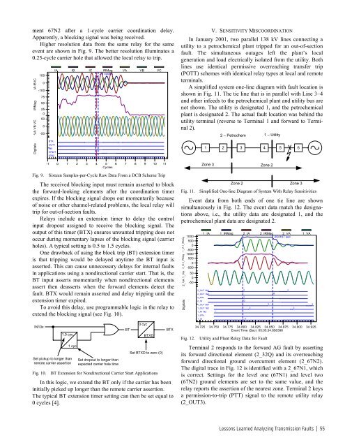
ment 67N2 after a 1-cycle carrier coordination delay.<br />
Apparently, a blocking signal was being received.<br />
Higher resolution data from the same relay for the same<br />
event are shown in Fig. 9. The better resolution illuminates a<br />
0.25-cycle carrier hole that allowed the local relay to trip.<br />
IA IB IC<br />
IRMag<br />
VA VB VC<br />
Digitals<br />
100<br />
0<br />
-100<br />
75<br />
50<br />
25<br />
0<br />
50<br />
0<br />
-50<br />
Fig. 9.<br />
BTX<br />
OUT1<br />
IN5<br />
67N2T<br />
67N2<br />
IA IB IC IRMag VA VB VC<br />
.25 cycles<br />
-1 0 1 2 3 4 5 6 7 8 9 10 11<br />
Cycles<br />
Sixteen Samples-per-Cycle Raw Data From a DCB Scheme Trip<br />
The received blocking input must remain asserted to block<br />
the forward-looking elements after the coordination timer<br />
expires. If the blocking signal drops out momentarily because<br />
<strong>of</strong> noise or other channel-related problems, the local relay will<br />
trip for out-<strong>of</strong>-section faults.<br />
Relays include an extension timer to delay the control<br />
input dropout assigned to receive the blocking signal. The<br />
output <strong>of</strong> this timer (BTX) ensures unwanted tripping does not<br />
occur during momentary lapses <strong>of</strong> the blocking signal (carrier<br />
holes). A typical setting is 0.5 to 1.5 cycles.<br />
One drawback <strong>of</strong> using the block trip (BT) extension timer<br />
is that tripping would be delayed anytime the BT input is<br />
asserted. This can cause unnecessary delays for internal faults<br />
in applications using a nondirectional carrier start. That is, the<br />
BT input asserts momentarily when nondirectional elements<br />
assert then deasserts when the forward elements detect the<br />
fault. BTX would remain asserted and delay tripping until the<br />
extension timer expired.<br />
To avoid this delay, use programmable logic in the relay to<br />
extend the blocking signal (see Fig. 10).<br />
IN10x<br />
1.0 cyc<br />
Set pickup to longer than<br />
remote carrier assertion<br />
Fig. 10.<br />
1 cyc<br />
Set dropout to longer than<br />
expected carrier hole time<br />
BT<br />
0 cyc<br />
BTXD<br />
Set BTXD to zero (0)<br />
BT Extension for Nondirectional Carrier Start Applications<br />
In this logic, we extend the BT only if the carrier has been<br />
initially picked up longer than the remote carrier assertion.<br />
The typical BT extension timer setting can then be set equal to<br />
0 cycles [4].<br />
BTX<br />
V. SENSITIVITY MISCOORDINATION<br />
In January 2001, two parallel 138 kV lines connecting a<br />
utility to a petrochemical plant tripped for an out-<strong>of</strong>-section<br />
fault. The simultaneous outages left the plant’s local<br />
generation and load electrically isolated from the utility. Both<br />
lines use identical permissive overreaching transfer trip<br />
(POTT) schemes with identical relay types at local and remote<br />
terminals.<br />
A simplified system one-line diagram with fault location is<br />
shown in Fig. 11. The tie line that is in parallel with Line 3–4<br />
and other infeeds to the petrochemical plant and utility bus are<br />
not shown. The utility is designated 1, and the petrochemical<br />
plant is designated 2. The actual fault location was behind the<br />
utility terminal (reverse to Terminal 1 and forward to Terminal<br />
2).<br />
2 – Petrochem 1 – Utility<br />
Fig. 11.<br />
1 2 3 4 5 6<br />
Zone 3 Zone 2<br />
Zone 2 Zone 3<br />
Simplified One-line Diagram <strong>of</strong> System With Relay Sensitivities<br />
Event data from both ends <strong>of</strong> one tie line are shown<br />
simultaneously in Fig. 12. The event data match the designations<br />
above, i.e., the utility data are designated 1, and the<br />
petrochemical plant data are designated 2.<br />
1_IA 1_IRMag<br />
2_IA 2_IRMag<br />
2_VA 1_VA<br />
Digitals<br />
1000<br />
500<br />
0<br />
-500<br />
1000<br />
500<br />
0<br />
-500<br />
50<br />
0<br />
-50<br />
Fig. 12.<br />
1_IA 1_IRMag 2_IA 2_IRMag 2_VA 1_VA<br />
.054167 sec<br />
2_OUT 3&4 3 3<br />
B<br />
2_OUT 1&2<br />
2_67N 1<br />
2_32 Q<br />
1_OUT 3&4 3 3<br />
1_OUT 1&2 2 2<br />
1_IN 1&2 1<br />
1_67N<br />
1_32 q<br />
34.725 34.750 34.775 34.800 34.825 34.850 34.875 34.900 34.925<br />
Event Time (Sec) 05:05:34.856396<br />
Utility and Plant Relay Data for Fault<br />
Terminal 2 responds to the forward AG fault by asserting<br />
its forward directional element (2_32Q) and its overreaching<br />
forward directional ground overcurrent element (2_67N2).<br />
The digital trace in Fig. 12 is identified with a 2_67N1, which<br />
is correct. Settings for the level one (67N1) and level two<br />
(67N2) ground elements are set to the same value, and the<br />
relay reports the assertion <strong>of</strong> the nearest zone. Terminal 2 keys<br />
a permission-to-trip (PTT) signal to the remote utility relay<br />
(2_OUT3).<br />
Lessons Learned Analyzing Transmission Faults | 55


