Magnetically Coded Safety Switches CMS - EUCHNER GmbH + Co ...
Magnetically Coded Safety Switches CMS - EUCHNER GmbH + Co ...
Magnetically Coded Safety Switches CMS - EUCHNER GmbH + Co ...

You also want an ePaper? Increase the reach of your titles
YUMPU automatically turns print PDFs into web optimized ePapers that Google loves.
EN<br />
DE<br />
<strong>Magnetically</strong> <strong><strong>Co</strong>ded</strong> <strong>Safety</strong> <strong>Switches</strong><br />
<strong>CMS</strong>
Internationally successful – the <strong>EUCHNER</strong> company<br />
Headquarters in Leinfelden-Echterdingen<br />
<strong>EUCHNER</strong> <strong>GmbH</strong> + <strong>Co</strong>. KG is a world-leading company in the area of industrial safety<br />
technology. <strong>EUCHNER</strong> has been developing and producing high-quality switching systems<br />
for mechanical and systems engineering for more than 50 years.<br />
The medium-sized family-operated company based in Leinfelden, Germany, employs<br />
more than 500 people around the world, 400 in Germany alone.<br />
In addition to the production locations in Unterböhringen and Shanghai/China, 14 subsidiaries<br />
and other sales partners in Germany and abroad work for our international<br />
success on the market.<br />
Quality and innovation – the <strong>EUCHNER</strong> products<br />
Logistics center in Leinfelden-Echterdingen<br />
A look into the past shows <strong>EUCHNER</strong> to be a company with a great inventive spirit.<br />
We take the technological and ecological challenges of the future as an incentive for<br />
extraordinary product developments.<br />
<strong>EUCHNER</strong> safety switches monitor safety doors on machines and installations, help to<br />
minimize dangers and risks and thereby reliably protect people and processes. Today,<br />
our products range from electromechanical and electronic components to intelligent<br />
integrated safety solutions. <strong>Safety</strong> for people, machines and products is one of our<br />
dominant themes.<br />
Production location in Unterböhringen<br />
made<br />
in<br />
Germany<br />
We defi ne future safety technology with the highest quality standards and reliable<br />
technology. Extraordinary solutions ensure the great satisfaction of our customers.<br />
The product ranges are subdivided as follows:<br />
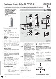
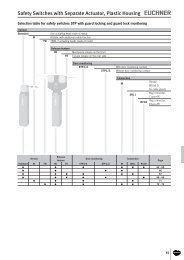
Transponder-coded <strong>Safety</strong> <strong>Switches</strong> (CES)<br />
Transponder-coded <strong>Safety</strong> <strong>Switches</strong> with guard locking (CET)<br />
Interlocking and guard locking systems (Multifunctional Gate Box MGB)<br />
Access management systems (Electronic-Key-System EKS)<br />
Electromechanical <strong>Safety</strong> <strong>Switches</strong><br />
<strong>Magnetically</strong> coded <strong>Safety</strong> <strong>Switches</strong> (<strong>CMS</strong>)<br />
Enabling <strong>Switches</strong><br />
<strong>Safety</strong> Relays<br />
Emergency Stop Devices<br />
Hand-Held Pendant Stations and Handwheels<br />
<strong>Safety</strong> <strong>Switches</strong> with AS-Interface<br />
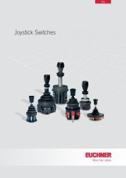
Joystick <strong>Switches</strong><br />
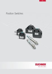
Position <strong>Switches</strong><br />
2
<strong>Co</strong>ntents<br />
Non-<strong>Co</strong>ntact <strong>Safety</strong> Systems <strong>CMS</strong><br />
System Overview 4<br />
Functional Description 5<br />
General Information 6<br />
Non-<strong>Co</strong>ntact <strong>Safety</strong> System <strong>CMS</strong>-E-AR 7<br />
Evaluation unit <strong>CMS</strong>-E-AR 8<br />
<strong>Co</strong>nnection examples safety system <strong>CMS</strong>-E-AR 10<br />
Read heads and actuators design A 12 - 15<br />
Read heads and actuators design B 16<br />
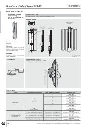
Read heads and actuators design C 18<br />
Read heads and actuators design E 20<br />
Non-<strong>Co</strong>ntact <strong>Safety</strong> System <strong>CMS</strong>-E-BR/<strong>CMS</strong>-E-ER/<strong>CMS</strong>-E-FR 23<br />
Evaluation unit <strong>CMS</strong>-E-BR 24<br />
Evaluation unit <strong>CMS</strong>-E-ER 26<br />
Evaluation unit <strong>CMS</strong>-E-FR 28<br />
<strong>Co</strong>nnection examples safety system <strong>CMS</strong>-E-BR 30<br />
<strong>Co</strong>nnection examples safety system <strong>CMS</strong>-E-ER 31<br />
<strong>Co</strong>nnection examples safety system <strong>CMS</strong>-E-FR 32<br />
Read heads and actuators design A 34<br />
Read heads and actuators design B 36<br />
Read heads and actuators design C 38<br />
Read heads and actuators design E 40<br />
Non-<strong>Co</strong>ntact <strong>Safety</strong> System for <strong>Safety</strong> Relay ESM 43<br />
<strong>Safety</strong> relays ESM-BA.. 44<br />
Read heads and actuators design A for ESM 50<br />
Read heads and actuators design B for ESM 52<br />
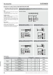
Accessories 54<br />
Item Index 55<br />
086824-08-10/12<br />
3
System Overview<br />
Evaluation unit Read heads Function<br />
Category<br />
acc. to<br />
EN ISO 13849-1<br />
1...2<br />
<strong>CMS</strong>-E-AR<br />
ff<br />
1 safety contact<br />
ff<br />
1 to 2 read heads (NO contacts wired in parallel) can be<br />
connected<br />
ff<br />
Category 3 according to EN ISO 13849-1<br />
ff<br />
PL d according to EN ISO 13849-1<br />
or<br />
Cat.<br />
3<br />
PLd<br />
ff<br />
3 to 30 read heads (NO contacts wired in series) can be<br />
connected<br />
3...30 ff<br />
Category 1 according to EN ISO 13849-1<br />
Cat.<br />
1<br />
ff<br />
PL c according to EN ISO 13849-1<br />
PLc<br />
ff<br />
(see page 8)<br />
1<br />
<strong>CMS</strong>-E-BR<br />
ff<br />
1 safety contact<br />
ff<br />
1 auxiliary contact<br />
ff<br />
1 feedback loop can be connected<br />
ff<br />
1 to 4 read heads can be connected<br />
ff<br />
Category 4 according to EN ISO 13849-1<br />
ff<br />
PL e according to EN ISO 13849-1<br />
or<br />
Cat.<br />
4<br />
PLe<br />
ff<br />
2 to 4 read heads can be connected<br />
ff<br />
Category 3 according to EN ISO 13849-1<br />
2...4 Cat.<br />
3<br />
ff<br />
PL d according to EN ISO 13849-1<br />
PLd<br />
(see page 24)<br />
1<br />
<strong>CMS</strong>-E-ER<br />
ff<br />
2 safety contacts<br />
ff<br />
1 auxiliary contact<br />
ff<br />
1 feedback loop can be connected<br />
ff<br />
1 read head can be connected<br />
ff<br />
Start button can be connected<br />
ff<br />
Category 4 according to EN ISO 13849-1<br />
ff<br />
PL e according to EN ISO 13849-1<br />
or<br />
Cat.<br />
4<br />
PLe<br />
ff<br />
2 to 30 read heads can be connected<br />
2...30 ff<br />
Category 3 according to EN ISO 13849-1<br />
Cat.<br />
3<br />
PLd<br />
ff<br />
PL d according to EN ISO 13849-1<br />
(see page 26)<br />
1<br />
<strong>CMS</strong>-E-FR<br />
ff<br />
2 safety contacts<br />
ff<br />
1 auxiliary contact<br />
ff<br />
6 monitoring outputs<br />
ff<br />
1 feedback loop can be connected<br />
ff<br />
1 read head can be connected<br />
ff<br />
Start button can be connected<br />
ff<br />
Category 4 according to EN ISO 13849-1<br />
ff<br />
PL e according to EN ISO 13849-1<br />
or<br />
Cat.<br />
4<br />
PLe<br />
ff<br />
2 to 30 read heads can be connected<br />
2...30 ff<br />
Category 3 according to EN ISO 13849-1<br />
Cat.<br />
3<br />
PLd<br />
ff<br />
PL d according to EN ISO 13849-1<br />
(see page 28)<br />
4<br />
Subject to technical modifications; no responsibility is accepted for the accuracy of this information.
General<br />
Functional Description<br />
The <strong><strong>Co</strong>ded</strong> Magnetic <strong>Safety</strong> systems <strong>CMS</strong> comprise three components:<br />
ff<br />
Actuator<br />
ff<br />
Read head<br />
ff<br />
Evaluation unit<br />
Several permanent magnets are accommodated in the actuator housing.<br />
The number of magnets, their position (polarization) in the housing and<br />
the magnetic field strength characterize the actuator type.<br />
For this reason they are also called coded actuators.<br />
Within a series, the individual actuator coding is identical. Using one<br />
actuator type on a machine or complete system allows for quick and<br />
easy replacement.<br />
Reed contacts are installed in the read head of the safety system <strong>CMS</strong>.<br />
The operating principle for the reed contacts (NC contacts or NO contacts),<br />
the number of reed contacts fitted and their physical arrangement<br />
determine the type of read head.<br />
The contact blades on the reed contacts will close when under the influence<br />
of the magnetic field from the actuator.<br />
The actuators and read heads are matched in pairs and are available in<br />
4 different housings.<br />
Depending on the application, the system operator can select a rectangular<br />
or cylindrical design.<br />
The read head only responds to the specific mating component, that is<br />
a specific actuator which is allocated to the read head type. The same<br />
applies to the allocation of the read head to the evaluation unit.<br />
The evaluation unit is the system unit which is downstream from the read<br />
head. Using internal relays, it switches the safety circuit as a function of<br />
the position of the reed contacts.<br />
The evaluation unit in degree of protection IP 20 is mounted in the control<br />
cabinet.<br />
<strong>EUCHNER</strong> offers various evaluation units. The unit is selected as a function<br />
of the number of read heads to be connected and the overall system<br />
category to be achieved according to EN ISO 13849‐1. The related evaluation<br />
units are described in detail in the following sections.<br />
In order to achieve a particular safety level, fault analyses must be carried<br />
out where safety-related components are used.<br />
A fault could be caused by a short circuit in the connecting lead or by<br />
welding of a reed contact in the closed position. If a reed contact is welded,<br />
the magnetic force might not be strong enough to open the contact. For<br />
reasons of safety, several reed contacts (2 or 3, depending on the switch<br />
type) are fitted to each read head.<br />
The NC contact/NO contact combination is used as an example. If the<br />
actuator is moved into the read head's operating distance, the reed contacts<br />
are switched by the magnets (in the actuator). Magnets with different<br />
polarization are assigned to the NC and NO contacts. The downstream<br />
evaluation unit monitors the read head: the NC/NO contacts in the read<br />
head must always have opposite states.<br />
If this is not the case, the safety contacts on the evaluation unit are not<br />
switched and the unit switches to the blocked state.<br />
If the actuator is moved away from the read head, the magnetic field<br />
around the reed contacts reduces with increasing distance. When the<br />
switch-off distance s ar<br />
is reached, the reed contacts return to their preloaded<br />
position (home position).<br />
The sensitivity of the reed contacts and the field strength of the magnets<br />
determine the switching distance between the actuator and the read head.<br />
Diagrams of the typical operating distances of the individual sensor units<br />
are shown in the technical data for the actuators and read heads.<br />
The illustration of the operating distance in x, y and z directions provides<br />
the user with information on how the actuator and read head must be<br />
positioned. When ideally positioned, the read head is in the middle of the<br />
operating distance.<br />
The actuator and read head sensor units have a large operating distance.<br />
The advantage of this fact is that the door clearance setting may vary<br />
within the limits of the operating distance.<br />
The safety systems <strong>CMS</strong> have switching characteristics with hysteresis<br />
(s ar<br />
> s ao<br />
).<br />
If the read head is adjusted just inside the actuator's s ao<br />
operating distance,<br />
the plant will not be switched off immediately if the door vibrates slightly.<br />
The switch-on and switch-off distances shown in the ordering tables refer<br />
to the approach of the sensor unit in the x direction (frontal approach<br />
direction). If the actuator approaches the read head from the side, the<br />
switching distances are likely to be reduced.<br />
The switch-on and switch-off distances in the x, y and z directions are<br />
given by the operating diagrams.<br />
An excessively low approach speed in the z direction (side approach direction)<br />
can result in an error in some evaluation units. For further information<br />
on the approach speed, refer to the individual product descriptions.<br />
The magnetic systems are notable for their high degree of protection and<br />
compact design. They are therefore particularly suitable for areas where<br />
dirt and cleaning are major factors.<br />
A major advantage of <strong>EUCHNER</strong>'s <strong>CMS</strong> safety switch is that the actuator<br />
and read head can be fitted behind stainless steel. This property makes<br />
it possible to use the system in the food industry in particular.<br />
The switching distances are, however, reduced in line with the material<br />
and wall thickness.<br />
Installation using the corrosion-resistant safety screws (supplied) provides<br />
tamper-proof mounting of the actuator and read head on the safety guard.<br />
The read head is fastened to the fixed part of the safety guard and is<br />
connected to the evaluation unit using a two-core or four-core cable.<br />
When the safety guard is closed, the actuator is moved towards the read<br />
head. As soon as there is an actuator in the operating distance (i.e. the<br />
switch-on distance s ao<br />
is reached) the reed contacts in the read head<br />
switch, i.e. they change their contact position.<br />
If the evaluation unit detects that the reed contacts are in a specific position<br />
on all read heads connected, i.e. all actuators are in the operating<br />
distance, the safety contact is switched on.<br />
Subject to technical modifications; no responsibility is accepted for the accuracy of this information.<br />
5
General<br />
General Information<br />
According to EN 1088, interlocking devices are mechanical or electrical<br />
devices which are designed to prevent the operation of a machine element<br />
for as long as the movable safety guard is left open.<br />
<strong>Safety</strong> switches without guard locking are used if the control concept is<br />
structured in such a way as to ensure that:<br />
ff<br />
the machine shuts down immediately upon opening the safety guard or<br />
ff<br />
the stop time (the time between the stop order being triggered by the<br />
interlocking device and the point of no further risk from hazardous<br />
machine function) is shorter than the access time.<br />
In the case of these safety switches, there are a number of different<br />
operating principles:<br />
ff<br />
Mechanical safety switches, e.g. <strong>EUCHNER</strong> safety switches series<br />
NZ, NP and NM<br />
ff<br />
Non-contact safety switches based on transponder technology, e.g.<br />
<strong>EUCHNER</strong> safety systems series CES<br />
ff<br />
Non-contact safety switches based on a magnetically coded principle,<br />
e.g. <strong>EUCHNER</strong> safety systems series <strong>CMS</strong><br />
<strong>Magnetically</strong> coded safety switches are interlocking devices which are<br />
designed to protect people and machines.<br />
<strong>Co</strong>mpared with electromechanical safety switches, they are used if:<br />
ff<br />
a high level of protection against tampering must be achieved<br />
ff<br />
strict hygiene requirements are to be met (e.g. in the food industry)<br />
ff<br />
a precise door guide is not possible<br />
ff<br />
machine doors are subjected to heavy vibration.<br />
The <strong>EUCHNER</strong> safety system <strong>CMS</strong> is based on the magnetic principle.<br />
The tamper-proof coded system was specifically developed to monitor<br />
moving machine components and movable safety guards.<br />
The<br />
safety system <strong>CMS</strong>... offers important<br />
advantages<br />
ff<br />
Non-contact safety guard monitoring<br />
ff<br />
No mechanical wear of the sensor units<br />
ff<br />
Long mechanical life (100 million operating cycles) of reed contacts<br />
ff<br />
The coding for all the actuators in a series is identical<br />
ff<br />
Quick easy replacement if required<br />
ff<br />
Evaluation units permit connection of various versions of actuators and<br />
read heads (whether rectangular or cylindrical)<br />
ff<br />
Actuator and read head have high degree of protection IP 67<br />
ff<br />
The actuator and read head can be fitted behind stainless steel<br />
ff<br />
Operates perfectly under extreme environmental conditions, e.g. dirt<br />
and moisture<br />
ff<br />
Large operating distance with hysteresis<br />
ff<br />
The sensor units can be approached from different directions<br />
ff<br />
Low costs with maximum benefits<br />
ff<br />
The rail in accordance with DIN EN 60715 TH35 ensures ease of assembly<br />
in the control cabinet.<br />
ff<br />
For connection to a safe control system with or without pulse signals<br />
ff<br />
LED displays<br />
ff<br />
Simplified diagnostics in case of service work<br />
ff<br />
Approval: TÜV and UL<br />
6<br />
Subject to technical modifications; no responsibility is accepted for the accuracy of this information.
Non-<strong>Co</strong>ntact <strong>Safety</strong> Systems <strong>CMS</strong><br />
Selection table for non-contact safety system <strong>CMS</strong>-E-AR<br />
Evaluation units <strong>Co</strong>nnection Design<br />
Read head<br />
contact<br />
assembly<br />
Assured switch-on distance<br />
S ao<br />
[mm]<br />
Assured switch-off distance<br />
S ar<br />
[mm]<br />
Number of<br />
read heads<br />
Category/<br />
PL<br />
according<br />
to<br />
EN ISO<br />
13849-1 Read head Actuator<br />
<strong>CMS</strong>-E-AR<br />
6 18<br />
<strong>CMS</strong>-R-AXD...<br />
<strong>CMS</strong>-M-AB<br />
Design A<br />
Page 12 - 15<br />
Rv<br />
18 34 CSM-R-AXE... <strong>CMS</strong>-M-AG<br />
9<br />
For<br />
contact<br />
status<br />
indication<br />
and<br />
LED: 7<br />
23<br />
For<br />
contact<br />
status<br />
indication<br />
and<br />
LED: 15<br />
1 ... 2 3 / PL d<br />
<strong>CMS</strong>-R-AXR...<br />
<strong>CMS</strong>-M-AI<br />
6 18<br />
<strong>CMS</strong>-R-AXF... <strong>CMS</strong>-M-AB<br />
3 ... 30 1 / PL c<br />
18 34 <strong>CMS</strong>-R-AXG... <strong>CMS</strong>-M-AG<br />
<strong>CMS</strong>-E-AR<br />
Design B<br />
6 17 1 ... 2 3 / PL d <strong>CMS</strong>-R-BXO...<br />
Hard-wired<br />
encapsulated<br />
connection cable/<br />
plug connector<br />
on the read head<br />
Page 16<br />
6 17 3 ... 30 1 / PL c <strong>CMS</strong>-R-BXP...<br />
<strong>CMS</strong>-M-BH<br />
Page 8<br />
Design C<br />
M25<br />
7 16 1 ... 2 3 / PL d <strong>CMS</strong>-R-CXA...<br />
<strong>CMS</strong>-M-CA<br />
Page 18<br />
7 16 3 ... 30 1 / PL c <strong>CMS</strong>-R-CXB...<br />
Design E<br />
M30<br />
7 16 1 ... 2 3 / PL d <strong>CMS</strong>-R-EXL...<br />
<strong>CMS</strong>-M-EF<br />
Page 20<br />
7 16 3 ... 30 1 / PL c <strong>CMS</strong>-R-EXN...<br />
Subject to technical modifications; no responsibility is accepted for the accuracy of this information.<br />
7
Non-<strong>Co</strong>ntact <strong>Safety</strong> Systems <strong>CMS</strong><br />
Evaluation unit <strong>CMS</strong>-E-AR<br />
ff<br />
Up to 30 read heads can be connected<br />
ff<br />
1 safety contact<br />
Evaluation unit <strong>CMS</strong>-E-AR<br />
Cat.<br />
1<br />
PLc<br />
Cat.<br />
3<br />
PLd<br />
Dimension drawing<br />
79,4 25<br />
74<br />
89<br />
Functional description<br />
The evaluation unit <strong>CMS</strong>-E-AR is suitable for the<br />
direct connection of up to 30 read heads.<br />
Suitable for 35 mm DIN rail acc. to DIN EN 60715 TH35<br />
A1<br />
A2<br />
13<br />
14<br />
1<br />
2<br />
3<br />
4<br />
5<br />
6<br />
7<br />
8<br />
Category/PL according to EN ISO 13849-1<br />
ff<br />
Category 1/PL c with 3 ... 30 read heads<br />
connected (NO contacts wired in series)<br />
ff<br />
Category 3/PL d with 1 ... 2 read heads connected<br />
(NO contacts wired in parallel)<br />
Block diagram<br />
A1<br />
D2<br />
A2<br />
D1<br />
UB<br />
1<br />
2<br />
3<br />
4<br />
13<br />
LED displays<br />
Actuator<br />
Channel 1<br />
in the operating<br />
distance<br />
Channel 2<br />
in the operating<br />
distance<br />
LED<br />
U B<br />
Operating<br />
voltage<br />
green<br />
l<br />
l<br />
D1<br />
green<br />
l<br />
D2<br />
green<br />
l<br />
gn<br />
channel 1<br />
K1<br />
K2<br />
channel 2<br />
gn<br />
D1<br />
K3<br />
gn<br />
D2<br />
<strong>CMS</strong>-E-AR<br />
5<br />
6<br />
7<br />
8<br />
14<br />
Ordering table<br />
Evaluation unit Scope of delivery Order No. / Item<br />
<strong>CMS</strong>-E-AR<br />
Evaluation unit<br />
One 3-pin jumper<br />
One 4-pin jumper<br />
085536<br />
<strong>CMS</strong>-E-AR<br />
8<br />
Subject to technical modifications; no responsibility is accepted for the accuracy of this information.
Non-<strong>Co</strong>ntact <strong>Safety</strong> Systems <strong>CMS</strong><br />
Technical data evaluation unit <strong>CMS</strong>-E-AR<br />
Parameter<br />
Housing material<br />
Value<br />
min. typ. max.<br />
Polyamide PA6.6<br />
Dimensions 89 x 79.4 x 25 mm<br />
Weight 0.13 kg<br />
Ambient temperature 0 - +50 °C<br />
Storage temperature -25 - +70 °C<br />
Degree of protection according to EN 60529 Terminals IP 20 / housing IP 40<br />
Degree of contamination 2<br />
Mounting<br />
Number of read heads<br />
<strong>Co</strong>nnection<br />
DIN rail 35 mm according to DIN EN 60715 TH35<br />
1 ... 30 in series 1) / 2 in parallel<br />
Plug-in connection terminals<br />
Operating voltage U B<br />
24 ±10% 2) V DC<br />
Internal fuse (operating voltage)<br />
(automatically resetting fuse PTC)<br />
Unit<br />
0.75 A<br />
Switching voltage U - - 250 V AC<br />
Current consumption - 70 - mA<br />
Switching current I at 24 V 2 - 3000 mA<br />
Breaking capacity P - - 750 VA<br />
External contact fuse (safety circuit)<br />
<strong>Safety</strong> contacts 1<br />
3 A gG<br />
Utilization category according to EN 60947-5-1 I e 3) U e 3)<br />
Switching load acc. to UL Class 2<br />
AC-1 3 A 250 V<br />
AC-15 0.9 A 250 V<br />
DC-13 1.8 A 24 V<br />
Input: 24 V AC/DC<br />
Output: 30 V AC / 24 V DC<br />
Rated insulation voltage U i<br />
250 V<br />
Vibration resistance According to EN 60947-5-2<br />
Mechanical operating cycles relays 10 x 10 6<br />
EMC compliance According to EN 60947-5-3<br />
Risk time according to EN 60947-5-3 10 ms<br />
Reliability values according to EN ISO 13849-1<br />
as a function of the switching current at 24 V DC ≤ = 0.1 A ≤ = 1 A ≤ = 3A<br />
Number of switching cycles/year < 96,000 < 75,000 < 18,000<br />
Mission time 20 years<br />
Category<br />
Performance Level (PL)<br />
PFH d<br />
2 read heads<br />
> 2 read heads<br />
2 read heads<br />
> 2 read heads<br />
2 read heads<br />
> 2 read heads<br />
3<br />
1<br />
d<br />
c<br />
4.3 x 10 --8<br />
1.1 x 10 -6<br />
1) For 3 m cable lengths. The number depends on the cable length.<br />
2) All the electrical connections must either be isolated from the mains supply by a safety transformer according to EN 61558-2-6 with limited output voltage in the event of a fault, or by other<br />
equivalent isolation measures.<br />
3) I e<br />
= max. switching current per contact, U e<br />
= switching voltage.<br />
Subject to technical modifications; no responsibility is accepted for the accuracy of this information.<br />
9
Non-<strong>Co</strong>ntact <strong>Safety</strong> Systems <strong>CMS</strong><br />
<strong>Co</strong>nnection examples evaluation unit <strong>CMS</strong>-E-AR<br />
<strong>Co</strong>nnection example 1<br />
ff<br />
One read head on one evaluation unit <strong>CMS</strong>-E-AR<br />
ff<br />
Read head 1: reed contacts wired in parallel<br />
read head 1<br />
<strong>Co</strong>nnection example 2<br />
ff<br />
Two read heads on one evaluation unit <strong>CMS</strong>-E-AR<br />
ff<br />
Read head 1 and 2: reed contacts wired in parallel<br />
read head 1<br />
BN<br />
GN<br />
YE<br />
WH<br />
BN<br />
GN<br />
YE<br />
WH<br />
1<br />
2<br />
3<br />
4<br />
1<br />
2<br />
3<br />
4<br />
Cat.<br />
3<br />
PLd<br />
<strong>CMS</strong>-E-AR<br />
5 6 7<br />
8<br />
Cat.<br />
3<br />
PLd<br />
<strong>CMS</strong>-E-AR<br />
5 6 7 8<br />
BN<br />
GN<br />
YE<br />
WH<br />
4-pin-jumper<br />
read head 2<br />
<strong>Co</strong>nnection example 3<br />
ff<br />
More than two read heads (max. of 30) on one evaluation unit <strong>CMS</strong>-E-AR<br />
ff<br />
Read head 1: reed contacts wired in parallel; read head 2 ... n: reed<br />
contacts wired in series<br />
read head 1<br />
BN GN YE WH<br />
1 2 3 4<br />
Cat.<br />
1<br />
PLc<br />
<strong>CMS</strong>-E-AR<br />
5 6 7<br />
8<br />
BN<br />
3-pol.-jumper<br />
WH<br />
WH<br />
BN<br />
read head 2<br />
read head 3...30<br />
Notes<br />
The following applies to all the illustrations:<br />
Evaluation unit electrically isolated, actuator not in the operating distance.<br />
10<br />
Subject to technical modifications; no responsibility is accepted for the accuracy of this information.
Non-<strong>Co</strong>ntact <strong>Safety</strong> Systems <strong>CMS</strong><br />
Subject to technical modifications; no responsibility is accepted for the accuracy of this information.<br />
11
Non-<strong>Co</strong>ntact <strong>Safety</strong> Systems <strong>CMS</strong><br />
Read heads and actuators design A<br />
ff<br />
For use with evaluation unit <strong>CMS</strong>-E-AR<br />
ff<br />
Cube-shaped version 88 x 25 mm<br />
ff<br />
With connection cable<br />
Read heads/actuators design A<br />
Dimension drawing<br />
Alignment of read head and actuator<br />
87,5<br />
67,5<br />
6<br />
25<br />
12<br />
9,5<br />
2,5 2,5<br />
6<br />
13<br />
2,5<br />
Y<br />
X<br />
Approach<br />
direction<br />
Z<br />
Alignment<br />
marking<br />
Actuator<br />
Active face<br />
Center offset m at s = 3 mm<br />
sao<br />
ca. ∅ 5,8<br />
0.34 mm²<br />
(6 x 0.25 mm²<br />
on <strong>CMS</strong>-R-AXR)<br />
∅ 5,5<br />
Note:<br />
The dimensions of the actuators are the same as<br />
those of the read heads, although the former have<br />
no connection cable or plug connector.<br />
78 ±0,1<br />
Yellow LED indicator<br />
Only on version <strong>CMS</strong>-R-AXR<br />
42<br />
Ordering table (Read heads and actuators each incl. 2 safety screws M4 x 14)<br />
Circuit diagram<br />
not actuated<br />
Rv<br />
BN<br />
YE<br />
GN<br />
WH<br />
BN<br />
WH<br />
BN<br />
YE<br />
GN<br />
WH<br />
PK<br />
GY<br />
Assured switch-on<br />
distance s ao<br />
[mm]<br />
Assured switch-off<br />
distance s ar<br />
[mm]<br />
6 18<br />
18 34<br />
6 18<br />
18 34<br />
9<br />
For contact status<br />
indication and LED:<br />
7<br />
23<br />
For contact status<br />
indication and LED:<br />
15<br />
Cable type<br />
V<br />
PVC<br />
P<br />
PUR<br />
V<br />
PVC<br />
P<br />
PUR<br />
V<br />
PVC<br />
P<br />
PUR<br />
V<br />
PVC<br />
P<br />
PUR<br />
V<br />
PVC<br />
P<br />
PUR<br />
Cable length<br />
[m]<br />
3<br />
5<br />
5<br />
1<br />
3<br />
5<br />
5<br />
3<br />
5<br />
5<br />
3<br />
5<br />
5<br />
5<br />
5<br />
Read head<br />
Order no./item<br />
084583<br />
<strong>CMS</strong>-R-AXD-03V<br />
085732<br />
<strong>CMS</strong>-R-AXD-05V<br />
103858<br />
<strong>CMS</strong>-R-AXD-05P<br />
102385<br />
<strong>CMS</strong>-R-AXE-01V<br />
084584<br />
<strong>CMS</strong>-R-AXE-03V<br />
085733<br />
<strong>CMS</strong>-R-AXE-05V<br />
103859<br />
<strong>CMS</strong>-R-AXE-05P<br />
084585<br />
<strong>CMS</strong>-R-AXF-03V<br />
085734<br />
<strong>CMS</strong>-R-AXF-05V<br />
103860<br />
<strong>CMS</strong>-R-AXF-05P<br />
084586<br />
<strong>CMS</strong>-R-AXG-03V<br />
085735<br />
<strong>CMS</strong>-R-AXG-05V<br />
103861<br />
<strong>CMS</strong>-R-AXG-05P<br />
093975 1)<br />
<strong>CMS</strong>-R-AXR-05VL<br />
103863 1)<br />
<strong>CMS</strong>-R-AXR-05PL<br />
Actuator<br />
Order no./item<br />
084591<br />
<strong>CMS</strong>-M-AB<br />
085654<br />
<strong>CMS</strong>-M-AG<br />
084591<br />
<strong>CMS</strong>-M-AB<br />
085654<br />
<strong>CMS</strong>-M-AG<br />
093976<br />
<strong>CMS</strong>-M-AI<br />
1) No approvals<br />
12<br />
Subject to technical modifications; no responsibility is accepted for the accuracy of this information.
10<br />
25<br />
Non-<strong>Co</strong>ntact <strong>Safety</strong> Systems <strong>CMS</strong><br />
Technical data read heads and actuators design A<br />
Parameter<br />
Value<br />
min. typ. max.<br />
Read heads<br />
Housing material<br />
Reinforced PPS<br />
Ambient temperature - 20 - +60 °C<br />
Degree of protection according to EN 60529 IP 67<br />
Installation position<br />
Any, alignment with actuator should be kept in mind (markings)<br />
<strong>Co</strong>nnection<br />
Molded cable with crimped ferrules<br />
Switching voltage 24 V<br />
Switching current I e<br />
- - 0.5 A<br />
<strong>Co</strong>ntact status indication (only <strong>CMS</strong>-A-AXR...)<br />
Switching voltage 24 V<br />
Switching current I e<br />
- - 0.015 A<br />
Method of operation<br />
Magnetic, reed contact<br />
Mechanical life<br />
100 x 10 6 operating cycles<br />
Vibration resistance<br />
10 ... 55 Hz, amplitude 1 mm<br />
Shock resistance<br />
30 g / 11 ms<br />
EMC compliance According to EN 60947-5-3<br />
Center offset m from actuator<br />
± 2.5 mm at a distance of s = 3 mm<br />
Switch-on distance s ao<br />
Switch-off distance s ar<br />
Switching contacts<br />
Actuator<br />
Housing material<br />
See ordering table<br />
and operating diagrams<br />
Reinforced PPS<br />
Ambient temperature - 20 - +60 °C<br />
Degree of protection according to EN 60529 IP 67<br />
Installation position<br />
Any, alignment with read head should be kept in mind (markings)<br />
Method of operation<br />
Magnetic<br />
Vibration resistance<br />
10 ... 55 Hz, amplitude 1 mm<br />
Shock resistance<br />
30 g / 11 ms<br />
Center offset m from read head<br />
± 2.5 mm at a distance of s = 3 mm<br />
Unit<br />
Switch-on distance s ao<br />
Switch-off distance s ar<br />
See ordering table<br />
and operating diagrams<br />
Operating diagrams design A<br />
<strong>CMS</strong>-R-AXD<br />
<strong>CMS</strong>-R-AXE<br />
<strong>CMS</strong>-R-AXF<br />
Y<br />
Y<br />
30<br />
25<br />
Y<br />
20<br />
20<br />
20<br />
15<br />
15<br />
15<br />
-20 5<br />
-30 -25 5<br />
-20 5<br />
10<br />
5<br />
10<br />
5<br />
10<br />
5<br />
10 15 20<br />
10 15 20 25 30<br />
10 15 20<br />
5<br />
5<br />
5<br />
5<br />
10<br />
Z<br />
10<br />
10 10<br />
Z<br />
X<br />
15<br />
15<br />
Z<br />
X<br />
15<br />
-15<br />
-20<br />
20<br />
-20<br />
X<br />
-30<br />
<strong>CMS</strong>-R-AXG<br />
<strong>CMS</strong>-R-AXR<br />
Y<br />
30<br />
Y<br />
25<br />
25<br />
-30 -25 5<br />
20<br />
15<br />
20<br />
15<br />
-25 5<br />
10<br />
5<br />
10<br />
5<br />
10 15 20 25 30<br />
10 15 20 25<br />
5<br />
5<br />
X<br />
25<br />
20<br />
15<br />
Z<br />
X<br />
20<br />
15<br />
10<br />
-25<br />
Z<br />
typical switch-on distance<br />
-30<br />
typical switch-off distance<br />
Subject to technical modifications; no responsibility is accepted for the accuracy of this information.<br />
13
Non-<strong>Co</strong>ntact <strong>Safety</strong> Systems <strong>CMS</strong><br />
Read heads and actuators design A<br />
ff<br />
For use with evaluation unit <strong>CMS</strong>-E-AR<br />
ff<br />
Cube-shaped version 88 x 25 mm<br />
ff<br />
With plug connector M8<br />
Read heads/actuators design A<br />
Dimension drawing<br />
87,5<br />
67,5<br />
7,2 ±0,25<br />
<strong>Co</strong>nnector assignment<br />
View of connection side<br />
Alignment of read head and actuator<br />
2<br />
4<br />
Y<br />
X<br />
Approach<br />
direction<br />
Z<br />
Alignment<br />
marking<br />
6<br />
25<br />
12<br />
9,5<br />
13<br />
2,5<br />
Actuator<br />
Center offset m at s = 3 mm<br />
2,5 2,5<br />
Active face<br />
sao<br />
1<br />
M8<br />
3<br />
7,2<br />
Note:<br />
The dimensions of the actuators are the same as<br />
those of the read heads, although the former have<br />
no connection cable or plug connector.<br />
5,5<br />
78 ±0,1<br />
5<br />
For connection cables see Accessories, page 54<br />
Ordering table (Read heads and actuators each incl. 2 safety screws M4 x 14)<br />
Circuit diagram<br />
not actuated<br />
1<br />
4<br />
3<br />
2<br />
1<br />
2<br />
Assured switch-on<br />
distance s ao<br />
[mm]<br />
Assured switch-off<br />
distance s ar<br />
[mm]<br />
Plug connectors<br />
6 18 M8<br />
18 34 M8<br />
6 18 M8<br />
18 34 M8<br />
Read head<br />
Order no./item<br />
100741<br />
<strong>CMS</strong>-R-AXD-SC<br />
100742<br />
<strong>CMS</strong>-R-AXE-SC<br />
100743<br />
<strong>CMS</strong>-R-AXF-SC<br />
100744<br />
<strong>CMS</strong>-R-AXG-SC<br />
Actuator<br />
Order no./item<br />
084591<br />
<strong>CMS</strong>-M-AB<br />
085654<br />
<strong>CMS</strong>-M-AG<br />
084591<br />
<strong>CMS</strong>-M-AB<br />
085654<br />
<strong>CMS</strong>-M-AG<br />
14<br />
Subject to technical modifications; no responsibility is accepted for the accuracy of this information.
25<br />
Non-<strong>Co</strong>ntact <strong>Safety</strong> Systems <strong>CMS</strong><br />
Technical data read heads and actuators design A<br />
Parameter<br />
Value<br />
min. typ. max.<br />
Read heads<br />
Housing material<br />
Reinforced PPS<br />
Ambient temperature - 20 - +60 °C<br />
Degree of protection according to EN 60529 IP 67<br />
Installation position<br />
Any, alignment with actuator should be kept in mind (markings)<br />
<strong>Co</strong>nnection<br />
M8 plug connector<br />
Switching voltage 24 V<br />
Switching current I e<br />
- - 0.5 A<br />
Method of operation<br />
Magnetic, reed contact<br />
Mechanical life<br />
100 x 10 6 operating cycles<br />
Vibration resistance<br />
10 ... 55 Hz, amplitude 1 mm<br />
Shock resistance<br />
30 g / 11 ms<br />
EMC compliance According to EN 60947-5-3<br />
Center offset m from actuator<br />
± 2.5 mm at a distance of s = 3 mm<br />
Switch-on distance s ao<br />
Switch-off distance s ar<br />
Switching contacts<br />
Actuator<br />
Housing material<br />
See ordering table<br />
and operating diagrams<br />
Reinforced PPS<br />
Ambient temperature - 20 - +60 °C<br />
Degree of protection according to EN 60529 IP 67<br />
Installation position<br />
Any, alignment with read head should be kept in mind (markings)<br />
Method of operation<br />
Magnetic<br />
Vibration resistance<br />
10 ... 55 Hz, amplitude 1 mm<br />
Shock resistance<br />
30 g / 11 ms<br />
Center offset m from read head<br />
± 2.5 mm at a distance of s = 3 mm<br />
Unit<br />
Switch-on distance s ao<br />
Switch-off distance s ar<br />
See ordering table<br />
and operating diagrams<br />
Operating diagrams design A<br />
<strong>CMS</strong>-R-AXD<br />
<strong>CMS</strong>-R-AXE<br />
Y<br />
30<br />
Y<br />
25<br />
20<br />
20<br />
-30 -25 5<br />
15<br />
15<br />
-20 5<br />
10<br />
5<br />
10<br />
5<br />
10 15 20<br />
10 15 20 25 30<br />
5<br />
5<br />
10<br />
Z<br />
10<br />
X<br />
15<br />
15<br />
Z<br />
-20<br />
20<br />
X<br />
-30<br />
<strong>CMS</strong>-R-AXG<br />
<strong>CMS</strong>-R-AXF<br />
Y<br />
30<br />
25<br />
Y<br />
-30 -25 5<br />
20<br />
15<br />
20<br />
15<br />
-20 5<br />
10<br />
5<br />
10<br />
5<br />
10 15 20 25 30<br />
10 15 20<br />
5<br />
5<br />
5<br />
10<br />
10 10<br />
Z<br />
20<br />
15<br />
Z<br />
X<br />
15<br />
-15<br />
-20<br />
typical switch-on distance<br />
X<br />
25<br />
-30<br />
typical switch-off distance<br />
Subject to technical modifications; no responsibility is accepted for the accuracy of this information.<br />
15
Non-<strong>Co</strong>ntact <strong>Safety</strong> Systems <strong>CMS</strong><br />
Read heads and actuators design B<br />
ff<br />
For use with evaluation unit <strong>CMS</strong>-E-AR<br />
ff<br />
Cube-shaped version 36 x 26 mm<br />
ff<br />
With connection cable or plug<br />
connector M8<br />
Read heads/actuators design B<br />
Dimension drawing<br />
With connection cable<br />
8,5<br />
19,2<br />
26,2<br />
13<br />
5<br />
Alignment of read head and actuator<br />
0,34 mm²<br />
ca. ∅ 5,8<br />
4,5<br />
Center offset m at s = 3 mm<br />
Actuator 2,5 2,5<br />
Active face<br />
Sao<br />
Y<br />
Approach<br />
direction<br />
Z<br />
X<br />
Alignment<br />
marking<br />
42<br />
22 7<br />
36<br />
With plug connector M8<br />
Note:<br />
The dimensions of the actuators are the same as<br />
those of the read heads, although the former have<br />
no connection cable or plug connector.<br />
<strong>Co</strong>nnector assignment<br />
View of connection side<br />
2<br />
4<br />
5,7<br />
12,9 ±0,25<br />
8,5<br />
5<br />
13<br />
1<br />
M8<br />
3<br />
Center offset m at s = 3 mm<br />
Actuator<br />
2,5 2,5<br />
Active face<br />
4,5<br />
sao<br />
17 9,2<br />
19,2<br />
26,2<br />
= =<br />
22<br />
36<br />
7<br />
For connection cables see Accessories, page 54<br />
Ordering table (Read heads and actuators each incl. 2 safety screws M4 x 14)<br />
Circuit diagram<br />
not actuated<br />
BN<br />
YE<br />
GN<br />
WH<br />
1<br />
4<br />
3<br />
2<br />
BN<br />
WH<br />
1<br />
2<br />
Assured switch-on<br />
distance s ao<br />
[mm]<br />
Assured switch-off<br />
distance s ar<br />
[mm]<br />
6 17<br />
6 17<br />
Cable type<br />
V<br />
PVC<br />
P<br />
PUR<br />
V<br />
PVC<br />
P<br />
PUR<br />
Plug connectors M8<br />
Plug connectors M8<br />
Cable length<br />
[m]<br />
5<br />
5<br />
5<br />
5<br />
Read head<br />
Order no./item<br />
092023<br />
<strong>CMS</strong>-R-BXO-05V<br />
103867<br />
<strong>CMS</strong>-R-BXO-05P<br />
100755<br />
<strong>CMS</strong>-R-BXO-SC<br />
092024<br />
<strong>CMS</strong>-R-BXP-05V<br />
103868<br />
<strong>CMS</strong>-R-BXP-05P<br />
100756<br />
<strong>CMS</strong>-R-BXP-SC<br />
Actuator<br />
Order no./item<br />
092025<br />
<strong>CMS</strong>-M-BH<br />
16<br />
Subject to technical modifications; no responsibility is accepted for the accuracy of this information.
5<br />
5<br />
Non-<strong>Co</strong>ntact <strong>Safety</strong> Systems <strong>CMS</strong><br />
Technical data read heads and actuators design B<br />
Parameter<br />
Read heads<br />
Housing material<br />
Value<br />
min. typ. max.<br />
Reinforced PPS<br />
Unit<br />
Ambient temperature - 20 - +60 °C<br />
Degree of protection according to EN 60529 IP 67<br />
Installation position<br />
<strong>Co</strong>nnection type<br />
Any, alignment with actuator should be kept in mind (markings)<br />
Molded cable with crimped ferrules / plug connector M8<br />
Switching current 24 V<br />
Switching current I e<br />
- - 0.5 A<br />
Method of operation<br />
Mechanical life<br />
Vibration resistance<br />
Shock resistance<br />
Magnetic, reed contact<br />
100 x 10 6 operating cycles<br />
10 ... 55 Hz, amplitude 1 mm<br />
30 g / 11 ms<br />
EMC compliance According to EN 60947-5-3<br />
Center offset m from actuator<br />
± 2.5 mm at a distance of s = 3 mm<br />
Switch-on distance S ao<br />
Switch-off distance S ar<br />
See ordering table and operating diagrams<br />
<strong>Co</strong>ntact elements<br />
Actuator<br />
Housing material<br />
Reinforced PPS<br />
Ambient temperature - 20 - +60 °C<br />
Degree of protection according to EN 60529 IP 67<br />
Installation position<br />
Method of operation<br />
Vibration resistance<br />
Shock resistance<br />
Center offset m from read head<br />
Any, alignment with read head should be kept in mind (markings)<br />
Magnetic<br />
10 ... 55 Hz, amplitude 1 mm<br />
30 g / 11 ms<br />
± 2.5 mm at a distance of s = 3 mm<br />
Switch-on distance S ao<br />
See ordering table and operating diagrams<br />
Switch-off distance S ar<br />
Operating diagrams design B<br />
<strong>CMS</strong>-R-BXO<br />
<strong>CMS</strong>-R-BXP<br />
Y<br />
25<br />
Y<br />
20<br />
20<br />
-25 -20<br />
15<br />
-20<br />
15<br />
10<br />
10<br />
5<br />
5<br />
5 10 15 20 25<br />
5 10 15 20<br />
10<br />
Z<br />
10<br />
Z<br />
X<br />
15<br />
15<br />
-20<br />
-20<br />
X<br />
20<br />
-25<br />
typical switch-on distance<br />
typical switch-off distance<br />
Subject to technical modifications; no responsibility is accepted for the accuracy of this information.<br />
17
Non-<strong>Co</strong>ntact <strong>Safety</strong> Systems <strong>CMS</strong><br />
Read heads and actuators design C<br />
ff<br />
In combination with evaluation units<br />
<strong>CMS</strong>-E-AR<br />
ff<br />
Cylindrical version M25<br />
ff<br />
With connection cable or<br />
plug connector M8<br />
Read heads design C<br />
Dimension drawing<br />
With connection cable<br />
42<br />
20<br />
36<br />
6<br />
s ao<br />
Alignment of read head and actuator<br />
Alignment<br />
marking<br />
M25x1,5<br />
0,34 mm²<br />
ca. ∅ 5,8<br />
With plug connector M8<br />
SW15<br />
SW32<br />
R1<br />
2,5<br />
2,5<br />
Actuator<br />
Center offset m<br />
at s = 3 mm<br />
Active face<br />
Y<br />
Approach<br />
direction<br />
Z<br />
X<br />
M25x1,5<br />
7,4 ±0,25<br />
5,2<br />
SW32<br />
Active face Actuator<br />
s ao<br />
2,5 2,5<br />
Center offset m at s = 3 mm<br />
M8<br />
9<br />
<strong>Co</strong>nnector<br />
assignment<br />
View of connection side<br />
4<br />
2<br />
3<br />
1<br />
6<br />
36<br />
For connection cables see Accessories, page 54<br />
Actuator design C<br />
Dimension drawing<br />
2<br />
15<br />
Active face<br />
Read head<br />
27,5<br />
∅ 25<br />
90°<br />
2,5 2,5<br />
Sao<br />
Center offset m<br />
at s = 3 mm<br />
∅5,5<br />
2,5<br />
13,4<br />
Ordering table (Actuator incl. 1 screw M5 x 25)<br />
Circuit diagram<br />
not actuated<br />
BN<br />
YE<br />
GN<br />
WH<br />
1<br />
4<br />
3<br />
2<br />
BN<br />
WH<br />
1<br />
Assured switch-on<br />
distance s ao<br />
[mm]<br />
Assured switch-off<br />
distance s ar<br />
[mm]<br />
7 16<br />
7 16<br />
Cable type<br />
V<br />
PVC<br />
P<br />
PUR<br />
V<br />
PVC<br />
P<br />
PUR<br />
Plug connectors M8<br />
Cable length<br />
[m]<br />
3<br />
5<br />
5<br />
3<br />
5<br />
5<br />
Read head<br />
Order no./item<br />
084574<br />
<strong>CMS</strong>-R-CXA-03V<br />
085739<br />
<strong>CMS</strong>-R-CXA-05V<br />
103870<br />
<strong>CMS</strong>-R-CXA-05P<br />
103965<br />
<strong>CMS</strong>-R-CXA-SC<br />
084576<br />
<strong>CMS</strong>-R-CXB-03V<br />
085740<br />
<strong>CMS</strong>-R-CXB-05V<br />
103871<br />
<strong>CMS</strong>-R-CXB-05P<br />
Actuator<br />
Order no./item<br />
084577<br />
<strong>CMS</strong>-M-CA<br />
2<br />
Plug connectors M8<br />
103966<br />
<strong>CMS</strong>-R-CXB-SC<br />
18<br />
Subject to technical modifications; no responsibility is accepted for the accuracy of this information.
Non-<strong>Co</strong>ntact <strong>Safety</strong> Systems <strong>CMS</strong><br />
Technical data read heads and actuators design C<br />
Parameter<br />
Value<br />
min. typ. max.<br />
Unit<br />
Read heads<br />
Housing material<br />
Reinforced PPS<br />
Ambient temperature - 20 - +60 °C<br />
Degree of protection according to EN 60529 IP 67<br />
Installation position<br />
Any, alignment with actuator should be kept in mind (markings)<br />
<strong>Co</strong>nnection type<br />
Molded cable with crimped ferrules / plug connector M8<br />
Switching current 24 V<br />
Switching current I e<br />
- - 0.5 A<br />
Method of operation<br />
Magnetic, reed contact<br />
Mechanical life<br />
100 x 10 6 operating cycles<br />
Vibration resistance<br />
10 ... 55 Hz, amplitude 1 mm<br />
Shock resistance<br />
30 g / 11 ms<br />
EMC compliance According to EN 60947-5-3<br />
Center offset m from actuator<br />
± 2.5 mm at a distance of s = 3 mm<br />
Switch-on distance S ao<br />
Switch-off distance S ar<br />
<strong>Co</strong>ntact elements<br />
Actuator<br />
Housing material<br />
See ordering table and operating diagrams<br />
Reinforced PPS<br />
Ambient temperature - 20 - +60 °C<br />
Degree of protection according to EN 60529 IP 67<br />
Installation position<br />
Any, alignment with read head should be kept in mind (markings)<br />
Method of operation<br />
Magnetic<br />
Vibration resistance<br />
10 ... 55 Hz, amplitude 1 mm<br />
Shock resistance<br />
30 g / 11 ms<br />
Center offset m from read head<br />
± 2.5 mm at a distance of s = 3 mm<br />
Switch-on distance S ao<br />
Switch-off distance S ar<br />
See ordering table and operating diagrams<br />
Operating diagrams design C<br />
<strong>CMS</strong>-R-CXA<br />
<strong>CMS</strong>-R-CXB<br />
Y<br />
-25<br />
25<br />
20<br />
15<br />
Y<br />
20<br />
15<br />
10<br />
5<br />
-20 -15<br />
10<br />
5<br />
5 10 15 20 25<br />
5 10 15 20<br />
5<br />
5<br />
X<br />
15<br />
10<br />
-20<br />
Z<br />
X<br />
15<br />
10<br />
-10<br />
-15<br />
-20<br />
Z<br />
typical switch-on distance<br />
typical switch-off distance<br />
Subject to technical modifications; no responsibility is accepted for the accuracy of this information.<br />
19
Non-<strong>Co</strong>ntact <strong>Safety</strong> Systems <strong>CMS</strong><br />
Read heads and actuators design E<br />
ff<br />
In combination with evaluation units<br />
<strong>CMS</strong>-E-AR<br />
ff<br />
Cylindrical version M30<br />
ff<br />
With connection cable or plug connector<br />
M8<br />
Read heads design E<br />
Dimension drawing<br />
42<br />
With connection cable<br />
20<br />
36<br />
8<br />
Sao<br />
Alignment of read head and actuator<br />
M30x1,5<br />
0,34 mm²<br />
ca. ∅ 5,8<br />
R1<br />
2,5 2,5<br />
Center offset m<br />
at s = 3 mm<br />
Alignment<br />
marking<br />
With plug connector M8<br />
SW15<br />
SW40<br />
Actuator<br />
Active face<br />
Y<br />
Approach<br />
direction<br />
Z<br />
X<br />
M30x1,5<br />
7,4 ±0,25<br />
5,2<br />
SW40<br />
Actuator<br />
Active face<br />
Sao<br />
2,5<br />
2,5<br />
Center offset m at s = 3 mm<br />
M8<br />
<strong>Co</strong>nnector<br />
assignment<br />
View of connection side<br />
9<br />
4<br />
2<br />
3<br />
1<br />
8<br />
36,2<br />
For connection cables see Accessories, page 54<br />
Actuator design E<br />
Dimension drawing<br />
2<br />
15<br />
Active face<br />
Read head<br />
32,6<br />
∅ 30<br />
90°<br />
2,5 2,5<br />
Sao<br />
Center offset m<br />
at s = 3 mm<br />
∅5,5<br />
2,5<br />
13<br />
Ordering table (Actuator incl. 1 screw M5 x 25)<br />
Circuit diagram<br />
not actuated<br />
BN<br />
YE<br />
GN<br />
WH<br />
1<br />
4<br />
3<br />
2<br />
BN<br />
WH<br />
1<br />
Assured switch-on<br />
distance s ao<br />
[mm]<br />
Assured switch-off<br />
distance s ar<br />
[mm]<br />
7 16<br />
7 16<br />
Cable type<br />
V<br />
PVC<br />
P<br />
PUR<br />
V<br />
PVC<br />
P<br />
PUR<br />
Plug connectors M8<br />
Cable length<br />
[m]<br />
3<br />
5<br />
5<br />
3<br />
5<br />
5<br />
Read head<br />
Order no./item<br />
085633<br />
<strong>CMS</strong>-R-EXL-03V<br />
085742<br />
<strong>CMS</strong>-R-EXL-05V<br />
103873<br />
<strong>CMS</strong>-R-EXL-05P<br />
103968<br />
<strong>CMS</strong>-R-EXL-SC<br />
085635<br />
<strong>CMS</strong>-R-EXN-03V<br />
085744<br />
<strong>CMS</strong>-R-EXN-05V<br />
103875<br />
<strong>CMS</strong>-R-EXN-05P<br />
Actuator<br />
Order no./item<br />
085636<br />
<strong>CMS</strong>-M-EF<br />
2<br />
Plug connectors M8<br />
103970<br />
<strong>CMS</strong>-R-EXN-SC<br />
20<br />
Subject to technical modifications; no responsibility is accepted for the accuracy of this information.
15<br />
Non-<strong>Co</strong>ntact <strong>Safety</strong> Systems <strong>CMS</strong><br />
Technical data read heads and actuators design E<br />
Parameter<br />
Read heads<br />
Housing material<br />
Value<br />
min. typ. max.<br />
Reinforced PPS<br />
Unit<br />
Ambient temperature - 20 - +60 °C<br />
Degree of protection according to EN 60529 IP 67<br />
Installation position<br />
<strong>Co</strong>nnection type<br />
Any, alignment with actuator should be kept in mind (markings)<br />
Molded cable with crimped ferrules / plug connector M8<br />
Switching current 24 V<br />
Switching current I e<br />
- - 0.5 A<br />
Method of operation<br />
Mechanical life<br />
Vibration resistance<br />
Shock resistance<br />
Magnetic, reed contact<br />
100 x 10 6 operating cycles<br />
10 ... 55 Hz, amplitude 1 mm<br />
30 g / 11 ms<br />
EMC compliance According to EN 60947-5-3<br />
Center offset m from actuator<br />
± 2.5 mm at a distance of s = 3 mm<br />
Switch-on distance S ao<br />
Switch-off distance S ar<br />
See ordering table and operating diagrams<br />
<strong>Co</strong>ntact elements<br />
Actuator<br />
Housing material<br />
Reinforced PPS<br />
Ambient temperature - 20 - +60 °C<br />
Degree of protection according to EN 60529 IP 67<br />
Installation position<br />
Method of operation<br />
Vibration resistance<br />
Shock resistance<br />
Center offset m from read head<br />
Any, alignment with read head should be kept in mind (markings)<br />
Magnetic<br />
10 ... 55 Hz, amplitude 1 mm<br />
30 g / 11 ms<br />
± 2.5 mm at a distance of s = 3 mm<br />
Switch-on distance S ao<br />
See ordering table and operating diagrams<br />
Switch-off distance S ar<br />
Operating diagrams design E<br />
<strong>CMS</strong>-R-EXL<br />
<strong>CMS</strong>-R-EXN<br />
Y<br />
-25<br />
25<br />
20<br />
15<br />
Y<br />
20<br />
15<br />
10<br />
5<br />
-20 -15<br />
10<br />
5<br />
5 10 15 20 20<br />
5 10 15 20<br />
5<br />
5<br />
10<br />
Z<br />
10<br />
Z<br />
X<br />
X<br />
15<br />
-15<br />
-20<br />
typical switch-on distance<br />
typical switch-off distance<br />
Subject to technical modifications; no responsibility is accepted for the accuracy of this information.<br />
21
Non-<strong>Co</strong>ntact <strong>Safety</strong> Systems <strong>CMS</strong><br />
22<br />
Subject to technical modifications; no responsibility is accepted for the accuracy of this information.
Non-<strong>Co</strong>ntact <strong>Safety</strong> Systems <strong>CMS</strong><br />
Selection table for non-contact safety system <strong>CMS</strong>-E-BR/<strong>CMS</strong>-E-ER/<strong>CMS</strong>-E-FR<br />
Evaluation<br />
units<br />
<strong>Co</strong>nnection<br />
Design<br />
Read head<br />
contact<br />
assembly<br />
Assured switch-on<br />
distance S ao<br />
[mm]<br />
Assured switch-on<br />
distance S ar<br />
[mm]<br />
Number of<br />
outputs<br />
Read heads<br />
Category/<br />
PL<br />
according<br />
to<br />
EN ISO<br />
13849-1<br />
Read head<br />
Actuator<br />
Design A<br />
<strong>CMS</strong>-E-BR<br />
1<br />
2 ... 4<br />
4 / PL e<br />
3 / PL d<br />
Page 34<br />
6 31<br />
<strong>CMS</strong>-E-ER/<strong>CMS</strong>-E-FR<br />
1 4 / PL e<br />
2 ... 30 3 / PL d<br />
<strong>CMS</strong>-R-AXH...<br />
<strong>CMS</strong>-M-AC<br />
Design B<br />
<strong>CMS</strong>-E-BR<br />
1<br />
2 ... 4<br />
4 / PL e<br />
3 / PL d<br />
<strong>CMS</strong>-E-BR<br />
<strong>CMS</strong>-E-ER<br />
<strong>CMS</strong>-E-FR<br />
Hard-wired<br />
encapsulated<br />
connection<br />
cable/plug<br />
connector<br />
on the<br />
read head<br />
Page 36<br />
Design C<br />
M25<br />
3 12<br />
<strong>CMS</strong>-E-ER/<strong>CMS</strong>-E-FR<br />
<strong>CMS</strong>-E-BR<br />
1 4 / PL e<br />
2 ... 30 3 / PL d<br />
1 4 / PL e<br />
2 ... 4 3 / PL d<br />
<strong>CMS</strong>-R-BXI...<br />
<strong>CMS</strong>-M-BD<br />
Page 24 - 29<br />
Page 38<br />
6 14<br />
<strong>CMS</strong>-E-ER/<strong>CMS</strong>-E-FR<br />
1 4 / PL e<br />
2 ... 30 3 / PL d<br />
<strong>CMS</strong>-R-CXC...<br />
<strong>CMS</strong>-M-CA<br />
Design E<br />
M30<br />
<strong>CMS</strong>-E-BR<br />
1<br />
2 ... 4<br />
4 / PL e<br />
3 / PL d<br />
Page 40<br />
6 17<br />
<strong>CMS</strong>-E-ER/<strong>CMS</strong>-E-FR<br />
1 4 / PL e<br />
2 ... 30 3 / PL d<br />
<strong>CMS</strong>-R-EXM...<br />
<strong>CMS</strong>-M-EF<br />
Subject to technical modifications; no responsibility is accepted for the accuracy of this information.<br />
23
Non-<strong>Co</strong>ntact <strong>Safety</strong> Systems <strong>CMS</strong><br />
Evaluation unit <strong>CMS</strong>-E-BR<br />
ff<br />
Up to 4 read heads can be connected<br />
ff<br />
1 safety contact<br />
ff<br />
1 auxiliary contact<br />
ff<br />
1 feedback loop can be connected<br />
Evaluation unit <strong>CMS</strong>-E-BR<br />
Dimension drawing<br />
75<br />
45<br />
Cat.<br />
3<br />
PLd<br />
Cat.<br />
4<br />
PLe<br />
105<br />
114,7<br />
Functional description<br />
The evaluation unit <strong>CMS</strong>-E-BR is suitable for the<br />
direct connection of up to 4 read heads.<br />
A1<br />
A2<br />
1<br />
2<br />
3<br />
4<br />
5<br />
6<br />
7<br />
8<br />
D21 D31<br />
D22<br />
D32<br />
Suitable for 35 mm DIN rail acc. to DIN EN 60715 TH35<br />
D11<br />
D41<br />
D12<br />
D42<br />
14<br />
13<br />
UB OUT<br />
Category/PL according to EN ISO 13849-1<br />
ff<br />
Category 3/PL d with more than one read<br />
head connected<br />
ff<br />
Category 4/PL e with only one read head<br />
connected<br />
Note:<br />
At low approach speeds in the z direction, the<br />
time between the switching the reed contacts<br />
must not be more than 150 ms.<br />
Block diagram<br />
A1 A2 1<br />
Y2<br />
Y1<br />
18<br />
17<br />
16<br />
15<br />
12<br />
11<br />
10<br />
9<br />
2<br />
D12<br />
rd<br />
3<br />
channel 1<br />
4<br />
24<br />
23<br />
5<br />
6<br />
D22<br />
rd<br />
7<br />
channel 2<br />
8<br />
13<br />
23<br />
D11<br />
gn<br />
K1<br />
gn<br />
D21<br />
gn<br />
D31<br />
gn<br />
gn<br />
D41<br />
control logic<br />
rd<br />
gn<br />
OUT<br />
K2<br />
K3<br />
K4<br />
channel 3<br />
D32<br />
channel 4<br />
D42<br />
feedback loop<br />
<strong>CMS</strong>-E-BR<br />
9<br />
10<br />
rd<br />
11<br />
12<br />
15<br />
16<br />
rd<br />
17<br />
18<br />
Y1<br />
Y2<br />
14<br />
24<br />
LED displays<br />
Actuator<br />
LED<br />
U B<br />
Operating<br />
voltage<br />
green<br />
Dx1<br />
green<br />
in the operating distance 1) l l l<br />
Dx2<br />
red<br />
green<br />
not in the operating distance 2) l l l<br />
not completely in the operating distance l l l l<br />
1) NC contact in the read head is open, NO contact in the read head is closed.<br />
All NO contacts in the previous channels are closed.<br />
2) NC contact in the read head is open, NO contact in the read head is closed.<br />
OUT<br />
red<br />
Ordering table<br />
Designation Scope of delivery Order No. / Item<br />
<strong>CMS</strong>-E-BR<br />
Evaluation unit<br />
Four 2-pin jumpers<br />
085537<br />
<strong>CMS</strong>-E-BR<br />
24<br />
Subject to technical modifications; no responsibility is accepted for the accuracy of this information.
Non-<strong>Co</strong>ntact <strong>Safety</strong> Systems <strong>CMS</strong><br />
Technical data evaluation unit <strong>CMS</strong>-E-BR<br />
Parameter<br />
Housing material<br />
Value<br />
min. typ. max.<br />
Polyamide PA6.6<br />
Dimensions 114.7 x 75 x 45 mm<br />
Weight 0.24 kg<br />
Ambient temperature 0 - +50 °C<br />
Storage temperature -25 - +70 °C<br />
Degree of protection according to EN 60529 Terminals IP 20 / housing IP 40<br />
Degree of contamination 2<br />
Mounting<br />
DIN rail 35 mm according to DIN EN 60715 TH35<br />
Number of read heads 1 ... 4<br />
<strong>Co</strong>nnection<br />
Plug-in connection terminals<br />
Operating voltage U B<br />
24 ±10% 1) V DC<br />
Internal fuse (operating voltage)<br />
(automatically resetting fuse PTC)<br />
Unit<br />
0.5 A<br />
Switching voltage U - - 250 V AC<br />
Current consumption - 250 mA<br />
Switching current I at 24 V 13 - 3000 mA<br />
Breaking capacity P - - 750 VA<br />
External contact fuse (safety circuit)<br />
<strong>Safety</strong> contact 1<br />
Auxiliary contact 1<br />
3 A gG<br />
Utilization category according to EN 60947-5-1 I e 2) U e 2)<br />
Switching load acc. to UL Class 2<br />
AC-1 3 A 250 V<br />
AC-1 3 A 24 V<br />
AC-15 1 A 250 V<br />
AC-15 1 A 24 V<br />
DC-13 3 A 24 V<br />
Input: 24 V AC/DC<br />
Output: 30 V AC / 24 V DC<br />
Rated insulation voltage U i<br />
250 V<br />
Vibration resistance According to EN 60947-5-2<br />
Mechanical operating cycles relays 30 x 10 6<br />
EMC compliance According to EN 60947-5-3<br />
Risk time according to EN 60947-5-3 20 ms<br />
Reliability values according to EN ISO 13849-1<br />
as a function of the switching current at 24 V DC ≤ = 0.1 A ≤ = 1 A ≤ = 3A<br />
Number of switching cycles/year < 100,000 < 18,500 < 9,000<br />
Mission time 20 years<br />
Category<br />
Performance Level (PL)<br />
PFH d<br />
1 read head<br />
>1 read head<br />
1 read head<br />
>1 read head<br />
1 read head<br />
>1 read head<br />
4<br />
3<br />
e<br />
d<br />
2.5 x 10 --8<br />
1.0 x 10 -7<br />
1) All the electrical connections must either be isolated from the mains supply by a safety transformer according to EN 61558-2-6 with limited output voltage in the event of a fault, or by other<br />
equivalent isolation measures.<br />
2) I e<br />
= max. switching current per contact, U e<br />
= switching voltage<br />
Subject to technical modifications; no responsibility is accepted for the accuracy of this information.<br />
25
Non-<strong>Co</strong>ntact <strong>Safety</strong> Systems <strong>CMS</strong><br />
Auswertegerät <strong>CMS</strong>-E-ER<br />
ff<br />
Up to 30 read heads can be connected<br />
ff<br />
2 safety contacts<br />
ff<br />
1 auxiliary contact<br />
ff<br />
1 feedback loop can be connected<br />
ff<br />
Start automatic/monitored/not monitored<br />
Evaluation unit <strong>CMS</strong>-E-ER<br />
Dimension drawing<br />
Cat.<br />
3<br />
PLd<br />
Cat.<br />
4<br />
PLe<br />
Functional description<br />
The evaluation unit <strong>CMS</strong>-E-ER is suitable for the<br />
direct connection of up to 30 read heads.<br />
A2<br />
A1<br />
<strong>Safety</strong> Switch <strong>CMS</strong><br />
H11 H22<br />
24 H12<br />
31 23 13<br />
Y1 Y2 Y3<br />
H73<br />
32<br />
Power<br />
K1<br />
K2<br />
22,5<br />
H74<br />
14<br />
Suitable for 35 mm DIN rail acc. to DIN EN 60715 TH35<br />
114<br />
99<br />
Category/PL according to EN ISO 13849-1<br />
ff<br />
Category 3/PL d with more than one read<br />
head connected<br />
ff<br />
Category 4/PL e with only one read head<br />
connected<br />
Block diagram<br />
Note:<br />
At low approach speeds in the z direction, the<br />
time between the switching the reed contacts<br />
must not be more than 0.6 ms.<br />
A1<br />
A2<br />
gn<br />
K1<br />
H11 H12 H22<br />
channel 1<br />
gn<br />
K2<br />
gn<br />
13<br />
23<br />
31<br />
K3<br />
channel 2<br />
Start/<br />
Feedback loop<br />
<strong>CMS</strong>-E-ER<br />
H73<br />
H74<br />
Y1<br />
Y2<br />
Y3<br />
14<br />
24<br />
32<br />
LED displays<br />
Actuator<br />
LED<br />
U B<br />
Operating<br />
voltage<br />
green<br />
K1<br />
Channel 1<br />
green<br />
K2<br />
Channel 2<br />
in the operating distance l l l<br />
none in the operating distance<br />
not completely in the operating distance l l or l<br />
l<br />
green<br />
Ordering table<br />
Designation Scope of delivery Order No. / Item<br />
Evaluation unit<br />
<strong>CMS</strong>-E-ER<br />
Evaluation unit<br />
One 2-pin jumper<br />
099182<br />
<strong>CMS</strong>-E-ER<br />
26<br />
Subject to technical modifications; no responsibility is accepted for the accuracy of this information.
Non-<strong>Co</strong>ntact <strong>Safety</strong> Systems <strong>CMS</strong><br />
Technical data evaluation unit <strong>CMS</strong>-E-ER<br />
Parameter<br />
Housing material<br />
Value<br />
min. typ. max.<br />
Polyamide PA6.6<br />
Dimensions 114 x 99 x 22.5 mm<br />
Weight 0.22 kg<br />
Ambient temperature 0 - +55 °C<br />
Storage temperature -25 - +70 °C<br />
Degree of protection according to EN 60529 Terminals IP 20 / housing IP 40<br />
Degree of contamination 2<br />
Mounting<br />
DIN rail 35 mm according to DIN EN 60715 TH35<br />
Number of read heads 1 ... 30<br />
<strong>Co</strong>nnection<br />
<strong>Co</strong>nnection terminals<br />
Operating voltage U B<br />
24 ±10% 1) V DC<br />
Internal fuse (operating voltage)<br />
(automatically resetting fuse PTC)<br />
<strong>Safety</strong> contacts<br />
Unit<br />
750 mA<br />
2 NO contacts<br />
Switching voltage U - - 240 V AC<br />
Current consumption at DC 24 V 10 - 120 mA<br />
Switching current I at 24 V - - 3 A<br />
Switching current I at 24 V 10 - - mA<br />
Breaking capacity P - - 720 VA<br />
External contact fuse<br />
(safety circuit acc. to EN IEC 60269-1)<br />
Auxiliary contact<br />
4 A gG<br />
1 NC contact<br />
Switching current I at 24 V - - 1.5 A<br />
Utilization category according to EN 60947-5-1 I e 2) U e 2)<br />
Switching load acc. to UL Class 2<br />
AC-1 3 A 230 V<br />
AC-1 3 A 24 V<br />
AC-15 0.9 A 240 V<br />
AC-15 0.9 A 24 V<br />
DC-13 1.5 A 24 V<br />
Input: 24 V AC/DC<br />
Output: 30 V AC / 24 V DC<br />
Rated insulation voltage U i<br />
250 V<br />
Vibration resistance According to EN 60947-5-2<br />
Mechanical operating cycles relays 10 x 10 6<br />
EMC compliance According to EN 60947-5-3<br />
Risk time according to EN 60947-5-3 20 ms<br />
Reliability values according to EN ISO 13849-1<br />
as a function of the switching current at 24 V DC ≤ = 0.1 A ≤ = 1 A<br />
Number of switching cycles/year < 166,000 < 70,000<br />
Mission time 20 years<br />
Category<br />
Performance Level (PL)<br />
PFH d<br />
1 read head<br />
>1 read head<br />
1 read head<br />
>1 read head<br />
1 read head<br />
>1 read head<br />
4<br />
3<br />
e<br />
d<br />
2.5 x 10 --8<br />
1.0 x 10 -7<br />
1) All the electrical connections must either be isolated from the mains supply by a safety transformer according to EN 61558-2-6 with limited output voltage in the event of a fault, or by other<br />
equivalent isolation measures.<br />
2) I e<br />
= max. switching current per contact, U e<br />
= switching voltage<br />
Subject to technical modifications; no responsibility is accepted for the accuracy of this information.<br />
27
Non-<strong>Co</strong>ntact <strong>Safety</strong> Systems <strong>CMS</strong><br />
Evaluation unit <strong>CMS</strong>-E-FR<br />
ff<br />
Up to 30 read heads can be connected<br />
ff<br />
2 safety contacts<br />
ff<br />
1 auxiliary contact<br />
ff<br />
6 monitoring outputs<br />
ff<br />
1 feedback loop can be connected<br />
ff<br />
Start automatic/monitored/not monitored<br />
Functional description<br />
The evaluation unit <strong>CMS</strong>-E-FR is suitable for the<br />
direct connection of up to 30 read heads.<br />
Evaluation unit <strong>CMS</strong>-E-FR<br />
Dimension drawing<br />
31 H11 13 23 H12 H31 H32 H42<br />
A1 Y1 Y2 Y3 H22 H51 H52 H62<br />
Power H1 H2<br />
K1<br />
H3 H4<br />
K2<br />
H5 H6<br />
A2 H73 H74 H83 H93 01 03 05<br />
32 14 H84 24 H94 02 04 06<br />
45<br />
Suitable for 35 mm DIN rail acc. to DIN EN 60715 TH35<br />
114<br />
99<br />
Cat.<br />
3<br />
PLd<br />
Cat.<br />
4<br />
PLe<br />
Category/PL according to EN ISO 13849-1<br />
ff<br />
Category 3/PL d with more than one read<br />
head connected<br />
ff<br />
Category 4/PL e with only one read head<br />
connected<br />
Block diagram<br />
Note:<br />
At low approach speeds in the z direction, the<br />
time between the switching the reed contacts<br />
must not be more than 0.6 ms.<br />
A1<br />
A2<br />
H11 H12 H22 H31 H32 H42 H51 H52 H62<br />
S1 S2<br />
S3 S4<br />
S5 S6<br />
channel 2a channel 2b channel 2c<br />
&<br />
13<br />
23<br />
31<br />
gn<br />
K1<br />
gn<br />
K2<br />
gn<br />
K3<br />
channel 1<br />
a | b | c<br />
Start/<br />
Feedback loop<br />
Monitoring outputs<br />
<strong>CMS</strong>-E-FR<br />
H73<br />
H74 H83<br />
H84H93<br />
H94<br />
Y1<br />
Y2<br />
Y3<br />
O1 O2 O3 O4 O5 O6<br />
14<br />
24<br />
32<br />
LED displays<br />
Actuator<br />
LED<br />
U B<br />
Operating<br />
voltage<br />
green<br />
K1<br />
Channel 1<br />
green<br />
K2<br />
Channel 2<br />
green<br />
H1 ... H6<br />
green<br />
in the operating distance l l l l 1)<br />
none in the operating distance<br />
not completely in the operating distance l l or l<br />
at least one not in the operating distance<br />
1) The LED indicator shows which actuators are in the operating distance.<br />
l<br />
l l 1)<br />
Ordering table<br />
Designation Scope of delivery Order No. / Item<br />
Evaluation unit<br />
<strong>CMS</strong>-E-FR<br />
Evaluation unit<br />
Two 3-pin jumpers<br />
099258<br />
<strong>CMS</strong>-E-FR<br />
28<br />
Subject to technical modifications; no responsibility is accepted for the accuracy of this information.
Non-<strong>Co</strong>ntact <strong>Safety</strong> Systems <strong>CMS</strong><br />
Technical data evaluation unit <strong>CMS</strong>-E-FR<br />
Parameter<br />
Housing material<br />
Value<br />
min. typ. max.<br />
Polyamide PA6.6<br />
Dimensions 114 x 99 x 45 mm<br />
Weight 0.3 kg<br />
Ambient temperature 0 - +55 °C<br />
Storage temperature -25 - +70 °C<br />
Degree of protection according to EN 60529 Terminals IP 20 / housing IP 40<br />
Degree of contamination 2<br />
Mounting<br />
DIN rail 35 mm according to DIN EN 60715 TH35<br />
Number of read heads 1 ... 30<br />
<strong>Co</strong>nnection<br />
<strong>Co</strong>nnection terminals<br />
Operating voltage U B<br />
24 ±10% 1) V DC<br />
Internal fuse (operating voltage)<br />
(automatically resetting fuse PTC)<br />
<strong>Safety</strong> contacts<br />
Unit<br />
750 mA<br />
2 NO contacts<br />
Switching voltage U - - 240 V AC<br />
Current consumption at DC 24 V 10 - 120 mA<br />
Switching current I at 24 V - - 3 A<br />
Switching current I at 24 V 10 - - mA<br />
Breaking capacity P - - 720 VA<br />
External contact fuse<br />
(safety circuit acc. to EN IEC 60269-1)<br />
Auxiliary contact<br />
4 A gG<br />
1 NC contact<br />
Switching current I at 24 V - - 1.5 A<br />
Monitoring output O1 ... O6<br />
DC 24 V / 50 mA per contact<br />
Utilization category according to EN 60947-5-1 I e 2) U e 2)<br />
Switching load acc. to UL Class 2<br />
AC-1 3 A 230 V<br />
AC-1 3 A 24 V<br />
AC-15 0.9 A 240 V<br />
AC-15 0.9 A 24 V<br />
DC-13 1.5 A 24 V<br />
Input: 24 V AC/DC<br />
Output: 30 V AC / 24 V DC<br />
Rated insulation voltage U i<br />
250 V<br />
Vibration resistance According to EN 60947-5-2<br />
Mechanical operating cycles relays 10 x 10 6<br />
EMC compliance According to EN 60947-5-3<br />
Risk time according to EN 60947-5-3 20 ms<br />
Reliability values according to EN ISO 13849-1<br />
as a function of the switching current at 24 V DC ≤ = 0.1 A ≤ = 1 A<br />
Number of switching cycles/year < 166,000 < 70,000<br />
Mission time 20 years<br />
Category<br />
Performance Level (PL)<br />
PFH d<br />
1 read head<br />
>1 read head<br />
1 read head<br />
>1 read head<br />
1 read head<br />
>1 read head<br />
4<br />
3<br />
e<br />
d<br />
2.5 x 10 --8<br />
1.0 x 10 -7<br />
1) All the electrical connections must either be isolated from the mains supply by a safety transformer according to EN 61558-2-6 with limited output voltage in the event of a fault, or by other<br />
equivalent isolation measures.<br />
2) I e<br />
= max. switching current per contact, U e<br />
= switching voltage<br />
Subject to technical modifications; no responsibility is accepted for the accuracy of this information.<br />
29
Non-<strong>Co</strong>ntact <strong>Safety</strong> Systems <strong>CMS</strong><br />
<strong>Co</strong>nnection examples evaluation unit <strong>CMS</strong>-E-BR<br />
<strong>Co</strong>nnection example 1<br />
ff<br />
One read head on one evaluation unit <strong>CMS</strong>-E-BR (without feedback loop)<br />
read head 1<br />
2-pin-jumper<br />
YE GN WH BN<br />
<strong>Co</strong>nnection examples for automatic start<br />
ff<br />
With feedback loop<br />
+24V<br />
feedback loop<br />
Y1 Y2<br />
13<br />
14<br />
23<br />
24<br />
ff<br />
Without feedback<br />
loop<br />
without<br />
feedback loop<br />
Y1 Y2<br />
Cat.<br />
4<br />
PLe<br />
1 2 3<br />
<strong>CMS</strong>-E-BR<br />
4<br />
5<br />
6<br />
7<br />
8<br />
K5<br />
K5<br />
2-pin-jumper<br />
9<br />
10<br />
11<br />
12<br />
15<br />
16<br />
17<br />
18<br />
GND<br />
2-pin-jumper<br />
2-pin-jumper<br />
<strong>Co</strong>nnection example 2<br />
ff<br />
Two read heads on one evaluation unit <strong>CMS</strong>-E-BR (without feedback loop)<br />
read head 1<br />
read head 2<br />
YE<br />
GN<br />
WH<br />
BN<br />
YE<br />
GN<br />
WH<br />
BN<br />
Cat.<br />
3<br />
PLd<br />
1 2 3<br />
<strong>CMS</strong>-E-BR<br />
4<br />
5<br />
6<br />
7<br />
8<br />
9<br />
10<br />
11<br />
12<br />
15<br />
16<br />
17<br />
18<br />
2-pin-jumper<br />
2-pin-jumper<br />
<strong>Co</strong>nnection example 3<br />
ff<br />
Four read heads on one evaluation unit <strong>CMS</strong>-E-BR (without feedback loop)<br />
read head 1<br />
read head 2<br />
YE<br />
GN<br />
WH<br />
BN<br />
YE<br />
GN<br />
WH<br />
BN<br />
1<br />
2<br />
3<br />
4<br />
5<br />
6<br />
7<br />
8<br />
Cat.<br />
3<br />
PLd<br />
<strong>CMS</strong>-E-BR<br />
9<br />
10<br />
11<br />
12<br />
15<br />
16<br />
17<br />
18<br />
YE GN WH BN YE GN WH BN<br />
read head 3<br />
read head 4<br />
Notes<br />
The following applies to all the illustrations:<br />
Evaluation unit electrically isolated, actuator not in the operating distance.<br />
30<br />
Subject to technical modifications; no responsibility is accepted for the accuracy of this information.
Non-<strong>Co</strong>ntact <strong>Safety</strong> Systems <strong>CMS</strong><br />
<strong>Co</strong>nnection examples evaluation unit <strong>CMS</strong>-E-ER<br />
<strong>Co</strong>nnection example 1<br />
ff<br />
One read head on one evaluation unit <strong>CMS</strong>-E-ER<br />
read head 1<br />
<strong>Co</strong>nnection examples for automatic start<br />
ff<br />
With feedback loop<br />
+24V<br />
ff<br />
Without feedback<br />
loop<br />
Cat.<br />
4<br />
PLe<br />
BN WH<br />
H11 H12 H22<br />
YE GN<br />
H73 H74<br />
Autostart<br />
with feedback loop<br />
Y1 Y2 Y3<br />
13<br />
14<br />
23<br />
24<br />
without<br />
feedback loop<br />
Y1 Y2 Y3<br />
<strong>CMS</strong>-E-ER<br />
K5<br />
K6<br />
K5<br />
K6<br />
2-pin-jumper<br />
GND<br />
<strong>Co</strong>nnection example 2<br />
ff<br />
Two read heads on one evaluation unit <strong>CMS</strong>-E-ER<br />
<strong>Co</strong>nnection examples for monitored start<br />
The safety contacts are closed only when the start button is released<br />
read head 2<br />
ff<br />
With feedback loop<br />
ff<br />
Without feedback<br />
loop<br />
BN<br />
WH<br />
YE<br />
GN<br />
+24V<br />
Cat.<br />
3<br />
PLd<br />
BN<br />
WH<br />
YE<br />
read head 1<br />
GN<br />
Start<br />
Monitored start<br />
with feedback loop<br />
Y1 Y2 Y3<br />
13<br />
14<br />
23<br />
24<br />
Start<br />
without<br />
feedback loop<br />
Y1 Y2 Y3<br />
H11<br />
H12<br />
H22<br />
H73<br />
H74<br />
K5<br />
K6<br />
<strong>CMS</strong>-E-ER<br />
K5<br />
K6<br />
GND<br />
<strong>Co</strong>nnection example 3<br />
ff<br />
More than 2 up to 30 read heads on one evaluation unit <strong>CMS</strong>-E-ER<br />
<strong>Co</strong>nnection examples for unmonitored start<br />
ff<br />
With feedback loop<br />
ff<br />
Without feedback<br />
loop<br />
read head 3...30<br />
+24V<br />
BN<br />
WH<br />
BN<br />
YE<br />
GN<br />
read head 2<br />
No monitored start<br />
with feedback loop<br />
Y1 Y2 Y3<br />
13<br />
14<br />
23<br />
24<br />
without<br />
feedback loop<br />
Y1 Y2 Y3<br />
Cat.<br />
3<br />
PLd<br />
WH<br />
BN<br />
YE<br />
GN<br />
read head 1<br />
Start<br />
K5<br />
K6<br />
K5<br />
K6<br />
Start<br />
WH<br />
YE<br />
GN<br />
GND<br />
H11<br />
H12<br />
H22<br />
H73<br />
H74<br />
<strong>CMS</strong>-E-ER<br />
Notes<br />
The following applies to all the illustrations:<br />
Evaluation unit electrically isolated, actuator not in the operating distance.<br />
Subject to technical modifications; no responsibility is accepted for the accuracy of this information.<br />
31
Non-<strong>Co</strong>ntact <strong>Safety</strong> Systems <strong>CMS</strong><br />
<strong>Co</strong>nnection examples evaluation unit <strong>CMS</strong>-E-FR<br />
<strong>Co</strong>nnection example 1<br />
ff<br />
One read head on one evaluation unit <strong>CMS</strong>-E-FR<br />
Cat.<br />
4<br />
PLe<br />
BN<br />
read head 1<br />
WH<br />
YE<br />
GN<br />
3-pin-jumper<br />
3-pin-jumper<br />
<strong>Co</strong>nnection examples for automatic start<br />
ff<br />
With feedback loop<br />
+24V<br />
Autostart<br />
with feedback loop<br />
Y1 Y2 Y3<br />
13<br />
14<br />
23<br />
24<br />
ff<br />
Without feedback<br />
loop<br />
without<br />
feedback loop<br />
Y1 Y2 Y3<br />
H11 H12 H22<br />
<strong>CMS</strong>-E-FR<br />
H73<br />
H74 H31 H32 H42 H83 H84 H51 H52 H62 H93 H94<br />
K5<br />
K6<br />
K5<br />
K6<br />
2-pin-jumper<br />
GND<br />
<strong>Co</strong>nnection example 2<br />
ff<br />
Three read heads on one evaluation unit <strong>CMS</strong>-E-FR<br />
<strong>Co</strong>nnection examples for monitored start<br />
The safety contacts are closed only when the start button is released<br />
Cat.<br />
3<br />
PLd<br />
ff<br />
With feedback loop<br />
+24V<br />
ff<br />
Without feedback<br />
loop<br />
BN<br />
read head 2 read head 1<br />
WH YE GN<br />
read head 3<br />
3-pin-jumper<br />
Monitored start<br />
with feedback loop<br />
Y1 Y2 Y3<br />
13<br />
14<br />
23<br />
24<br />
without<br />
feedback loop<br />
Y1 Y2 Y3<br />
BN<br />
WH<br />
YE<br />
GN<br />
BN<br />
WH<br />
YE<br />
GN<br />
H11<br />
H12<br />
H22<br />
H73<br />
H74<br />
H31<br />
H32<br />
H42<br />
H83<br />
H84 H51 H52 H62 H93 H94<br />
Start<br />
Start<br />
<strong>CMS</strong>-E-FR<br />
K5<br />
K6<br />
K5<br />
K6<br />
GND<br />
<strong>Co</strong>nnection example 3<br />
ff<br />
Six read heads on one evaluation unit <strong>CMS</strong>-E-FR<br />
Cat.<br />
3<br />
PLd<br />
<strong>Co</strong>nnection examples for unmonitored start<br />
ff<br />
With feedback loop<br />
+24V<br />
ff<br />
Without feedback<br />
loop<br />
read head 1 + 2 read head 3 + 4 read head 5 + 6<br />
#2<br />
#4<br />
#6<br />
BN<br />
WH YE GN BN<br />
WH YE GN BN<br />
WH YE<br />
GN<br />
No monitored start<br />
with feedback loop<br />
Y1 Y2 Y3<br />
13<br />
14<br />
23<br />
24<br />
without<br />
feedback loop<br />
Y1 Y2 Y3<br />
#1<br />
#3<br />
#5<br />
BN<br />
H11<br />
WH<br />
H12<br />
H22<br />
YE<br />
H73<br />
GN<br />
H74<br />
BN<br />
H31<br />
WH<br />
H32<br />
H42<br />
YE<br />
H83<br />
GN<br />
H84<br />
BN<br />
H51<br />
WH<br />
H52<br />
H62<br />
YE<br />
H93<br />
GN<br />
H94<br />
Start<br />
Start<br />
<strong>CMS</strong>-E-FR<br />
K5<br />
K6<br />
K5<br />
K6<br />
GND<br />
32<br />
Subject to technical modifications; no responsibility is accepted for the accuracy of this information.
Non-<strong>Co</strong>ntact <strong>Safety</strong> Systems <strong>CMS</strong><br />
Subject to technical modifications; no responsibility is accepted for the accuracy of this information.<br />
33
Non-<strong>Co</strong>ntact <strong>Safety</strong> Systems <strong>CMS</strong><br />
Read heads and actuators design A<br />
ff<br />
In combination with evaluation units<br />
<strong>CMS</strong>-E-BR/<strong>CMS</strong>-E-ER/<strong>CMS</strong>-E-FR<br />
ff<br />
Cube-shaped version 88 x 25 mm<br />
ff<br />
With connection cable or plug<br />
connector M8<br />
Read heads/actuators design A<br />
Dimension drawing<br />
With connection cable<br />
87,5<br />
67,5<br />
13<br />
2,5<br />
6<br />
Center offset m at s = 3 mm<br />
Alignment of read head and actuator<br />
Y<br />
X<br />
25<br />
12<br />
Actuator<br />
Active face<br />
9,5<br />
2,5 2,5<br />
Sao<br />
ca. ∅ 5,8<br />
0.34 mm²<br />
Approach<br />
direction<br />
Z<br />
Alignment<br />
marking<br />
6<br />
∅ 5,5<br />
78 ±0,1<br />
42<br />
With plug connector M8<br />
Note:<br />
The dimensions of the actuators are the same as<br />
those of the read heads, although the former have<br />
no connection cable or plug connector.<br />
13<br />
2,5<br />
87,5<br />
67,5<br />
7,2 ±0,25<br />
<strong>Co</strong>nnector assignment<br />
View of connection side<br />
2<br />
4<br />
Actuator<br />
Center offset m at s = 3 mm<br />
2,5 2,5<br />
1<br />
3<br />
Active face<br />
sao<br />
M8<br />
6<br />
7,2<br />
25<br />
12<br />
9,5<br />
5,5<br />
5<br />
78 ±0,1<br />
For connection cables see Accessories, page 54<br />
Ordering table (Read heads and actuators each incl. 2 safety screws M4 x 14)<br />
Circuit diagram<br />
not actuated<br />
Assured switchon<br />
distance s ao<br />
[mm]<br />
Assured switchoff<br />
distance s ar<br />
[mm]<br />
Cable type<br />
Cable length<br />
[m]<br />
Read head<br />
Order no./item<br />
Actuator<br />
Order no./item<br />
BN<br />
WH<br />
GN<br />
YE<br />
1<br />
2<br />
3<br />
4<br />
6 31<br />
V<br />
PVC<br />
P<br />
PUR<br />
Plug connectors M8<br />
3<br />
5<br />
5<br />
084587<br />
<strong>CMS</strong>-R-AXH-03V<br />
085736<br />
<strong>CMS</strong>-R-AXH-05V<br />
103862<br />
<strong>CMS</strong>-R-AXH-05P<br />
100745<br />
<strong>CMS</strong>-R-AXH-SC<br />
084592<br />
<strong>CMS</strong>-M-AC<br />
34<br />
Subject to technical modifications; no responsibility is accepted for the accuracy of this information.
Non-<strong>Co</strong>ntact <strong>Safety</strong> Systems <strong>CMS</strong><br />
Technical data read heads and actuators design A<br />
Parameter<br />
Read heads<br />
Housing material<br />
Value<br />
min. typ. max.<br />
Reinforced PPS<br />
Unit<br />
Ambient temperature - 20 - +60 °C<br />
Degree of protection according to EN 60529 IP 67<br />
Installation position<br />
<strong>Co</strong>nnection type<br />
Any, alignment with read head should be kept in mind (markings)<br />
Molded cable with crimped ferrules / plug connector M8<br />
Switching current 24 V<br />
Switching current I e<br />
- - 0.5 A<br />
Method of operation<br />
Mechanical life<br />
Vibration resistance<br />
Shock resistance<br />
Magnetic, reed contact<br />
100 x 10 6 operating cycles<br />
10 ... 55 Hz, amplitude 1 mm<br />
30 g / 11 ms<br />
EMC compliance According to EN 60947-5-3<br />
Center offset m from actuator<br />
± 2.5 mm at a distance of s = 3 mm<br />
Switch-on distance S ao<br />
Switch-off distance S ar<br />
See ordering table and operating diagrams<br />
<strong>Co</strong>ntact elements<br />
Actuator<br />
Housing material<br />
Reinforced PPS<br />
Ambient temperature - 20 - +60 °C<br />
Degree of protection according to EN 60529 IP 67<br />
Installation position<br />
Method of operation<br />
Vibration resistance<br />
Shock resistance<br />
Center offset m from read head<br />
Any, alignment with read head should be kept in mind (markings)<br />
Magnetic<br />
10 ... 55 Hz, amplitude 1 mm<br />
30 g / 11 ms<br />
± 2.5 mm at a distance of s = 3 mm<br />
Switch-on distance S ao<br />
See ordering table and operating diagrams<br />
Switch-off distance S ar<br />
Operating diagrams design A<br />
Y<br />
20<br />
-20<br />
15<br />
10<br />
5<br />
5 10 15 20<br />
5<br />
10<br />
Z<br />
15<br />
X<br />
-20<br />
typical switch-on distance<br />
typical switch-off distance<br />
Subject to technical modifications; no responsibility is accepted for the accuracy of this information.<br />
35
Non-<strong>Co</strong>ntact <strong>Safety</strong> Systems <strong>CMS</strong><br />
Read heads and actuators design B<br />
ff<br />
In combination with evaluation units<br />
<strong>CMS</strong>-E-BR/<strong>CMS</strong>-E-ER/<strong>CMS</strong>-E-FR<br />
ff<br />
Cube-shaped version 36 x 26 mm<br />
ff<br />
With connection cable or plug<br />
connector M8<br />
Read heads/actuators design B<br />
Dimension drawing<br />
With connection cable<br />
8,5<br />
Center offset m at s = 3 mm<br />
Actuator 2,5 2,5<br />
Active face<br />
19,2<br />
26,2<br />
13<br />
5<br />
4,5<br />
Alignment of read head and actuator<br />
0,34 mm²<br />
ca. ∅ 5,8<br />
Sao<br />
Y<br />
Approach<br />
direction<br />
Z<br />
X<br />
Alignment<br />
marking<br />
42<br />
22 7<br />
36<br />
With plug connector M8<br />
Note:<br />
The dimensions of the actuators are the same as<br />
those of the read heads, although the former have<br />
no connection cable or plug connector.<br />
<strong>Co</strong>nnector assignment<br />
View of connection side<br />
2<br />
4<br />
5,7<br />
12,9 ±0,25<br />
8,5<br />
5<br />
13<br />
1<br />
M8<br />
3<br />
Center offset m at s = 3 mm<br />
Actuator<br />
2,5 2,5<br />
Active face<br />
4,5<br />
sao<br />
17 9,2<br />
19,2<br />
26,2<br />
= =<br />
22<br />
36<br />
7<br />
For connection cables see Accessories, page 54<br />
Ordering table (Read heads and actuators each incl. 2 safety screws M4 x 14)<br />
Circuit diagram<br />
not actuated<br />
Assured switchon<br />
distance s ao<br />
[mm]<br />
Assured switchoff<br />
distance s ar<br />
[mm]<br />
Cable type<br />
Cable length<br />
[m]<br />
Read head<br />
Order no./item<br />
Actuator<br />
Order no./item<br />
BN<br />
WH<br />
GN<br />
YE<br />
1<br />
2<br />
3<br />
4<br />
3 12<br />
V<br />
PVC<br />
P<br />
PUR<br />
3<br />
5<br />
5<br />
7<br />
085530<br />
<strong>CMS</strong>-R-BXI-03V<br />
085737<br />
<strong>CMS</strong>-R-BXI-05V<br />
103866<br />
<strong>CMS</strong>-R-BXI-05P<br />
115117<br />
<strong>CMS</strong>-R-BXI-07P<br />
085531<br />
<strong>CMS</strong>-M-BD<br />
Plug connectors M8<br />
100696<br />
<strong>CMS</strong>-R-BXI-SC<br />
36<br />
Subject to technical modifications; no responsibility is accepted for the accuracy of this information.
Non-<strong>Co</strong>ntact <strong>Safety</strong> Systems <strong>CMS</strong><br />
Technical data read heads and actuators design B<br />
Parameter<br />
Read heads<br />
Housing material<br />
Value<br />
min. typ. max.<br />
Reinforced PPS<br />
Unit<br />
Ambient temperature - 20 - +60 °C<br />
Degree of protection according to EN 60529 IP 67<br />
Installation position<br />
<strong>Co</strong>nnection type<br />
Any, alignment with read head should be kept in mind (markings)<br />
Molded cable with crimped ferrules / plug connector M8<br />
Switching current 24 V<br />
Switching current I e<br />
- - 0.5 A<br />
Method of operation<br />
Mechanical life<br />
Vibration resistance<br />
Shock resistance<br />
Magnetic, reed contact<br />
100 x 10 6 operating cycles<br />
10 ... 55 Hz, amplitude 1 mm<br />
30 g / 11 ms<br />
EMC compliance According to EN 60947-5-3<br />
Center offset m from actuator<br />
± 2.5 mm at a distance of s = 3 mm<br />
Switch-on distance S ao<br />
Switch-off distance S ar<br />
See ordering table and operating diagrams<br />
<strong>Co</strong>ntact elements<br />
Actuator<br />
Housing material<br />
Reinforced PPS<br />
Ambient temperature - 20 - +60 °C<br />
Degree of protection according to EN 60529 IP 67<br />
Installation position<br />
Method of operation<br />
Vibration resistance<br />
Shock resistance<br />
Center offset m from read head<br />
Any, alignment with read head should be kept in mind (markings)<br />
Magnetic<br />
10 ... 55 Hz, amplitude 1 mm<br />
30 g / 11 ms<br />
± 2.5 mm at a distance of s = 3 mm<br />
Switch-on distance S ao<br />
See ordering table and operating diagrams<br />
Switch-off distance S ar<br />
Operating diagrams design B<br />
Y<br />
20<br />
-20<br />
15<br />
10<br />
5<br />
5 10 15 20<br />
5<br />
10<br />
Z<br />
15<br />
X<br />
-20<br />
typical switch-on distance<br />
typical switch-off distance<br />
Subject to technical modifications; no responsibility is accepted for the accuracy of this information.<br />
37
Non-<strong>Co</strong>ntact <strong>Safety</strong> Systems <strong>CMS</strong><br />
Read heads and actuators design C<br />
ff<br />
In combination with evaluation units<br />
<strong>CMS</strong>-E-BR/<strong>CMS</strong>-E-ER/<strong>CMS</strong>-E-FR<br />
ff<br />
Cylindrical version M25<br />
ff<br />
With connection cable or plug<br />
connector M8<br />
Read heads design C<br />
Dimension drawing<br />
With connection cable<br />
42<br />
20<br />
36<br />
6<br />
s ao<br />
Alignment of read head and actuator<br />
Alignment<br />
marking<br />
M25x1,5<br />
0,34 mm²<br />
ca. ∅ 5,8<br />
With plug connector M8<br />
SW15<br />
SW32<br />
R1<br />
2,5<br />
2,5<br />
Actuator<br />
Center offset m<br />
at s = 3 mm<br />
Active face<br />
Y<br />
Approach<br />
direction<br />
Z<br />
X<br />
M25x1,5<br />
7,4 ±0,25<br />
5,2<br />
SW32<br />
Active face Actuator<br />
s ao<br />
2,5 2,5<br />
Center offset m at s = 3 mm<br />
M8<br />
9<br />
<strong>Co</strong>nnector<br />
assignment<br />
View of connection side<br />
4<br />
2<br />
3<br />
1<br />
6<br />
36<br />
For connection cables see Accessories, page 54<br />
Actuator design C<br />
Dimension drawing<br />
2<br />
15<br />
Active face<br />
Read head<br />
27,5<br />
∅ 25<br />
90°<br />
2,5 2,5<br />
Sao<br />
Center offset m<br />
at s = 3 mm<br />
∅5,5<br />
2,5<br />
13,4<br />
Ordering table (Actuator incl. 1 screw M5 x 25)<br />
Circuit diagram<br />
not actuated<br />
Assured switchon<br />
distance s ao<br />
[mm]<br />
Assured switchoff<br />
distance s ar<br />
[mm]<br />
Cable type<br />
Cable length<br />
[m]<br />
Read head<br />
Order no./item<br />
Actuator<br />
Order no./item<br />
BN<br />
WH<br />
GN<br />
YE<br />
1<br />
2<br />
3<br />
4<br />
6 14<br />
V<br />
PVC<br />
P<br />
PUR<br />
Plug connectors M8<br />
3<br />
5<br />
5<br />
084575<br />
<strong>CMS</strong>-R-CXC-03V<br />
085741<br />
<strong>CMS</strong>-R-CXC-05V<br />
103872<br />
<strong>CMS</strong>-R-CXC-05P<br />
103967<br />
<strong>CMS</strong>-R-CXC-SC<br />
084577<br />
<strong>CMS</strong>-M-CA<br />
38<br />
Subject to technical modifications; no responsibility is accepted for the accuracy of this information.
15<br />
Non-<strong>Co</strong>ntact <strong>Safety</strong> Systems <strong>CMS</strong><br />
Technical data read heads and actuators design C<br />
Parameter<br />
Read heads<br />
Housing material<br />
Value<br />
min. typ. max.<br />
Reinforced PPS<br />
Unit<br />
Ambient temperature - 20 - +60 °C<br />
Degree of protection according to EN 60529 IP 67<br />
Installation position<br />
<strong>Co</strong>nnection type<br />
Any, alignment with read head should be kept in mind (markings)<br />
Molded cable with crimped ferrules / plug connector M8<br />
Switching current 24 V<br />
Switching current I e<br />
- - 0.5 A<br />
Method of operation<br />
Mechanical life<br />
Vibration resistance<br />
Shock resistance<br />
Magnetic, reed contact<br />
100 x 10 6 operating cycles<br />
10 ... 55 Hz, amplitude 1 mm<br />
30 g / 11 ms<br />
EMC compliance According to EN 60947-5-3<br />
Center offset m from actuator<br />
± 2.5 mm at a distance of s = 3 mm<br />
Switch-on distance S ao<br />
Switch-off distance S ar<br />
See ordering table and operating diagrams<br />
<strong>Co</strong>ntact elements<br />
Actuator<br />
Housing material<br />
Reinforced PPS<br />
Ambient temperature - 20 - +60 °C<br />
Degree of protection according to EN 60529 IP 67<br />
Installation position<br />
Method of operation<br />
Vibration resistance<br />
Shock resistance<br />
Center offset m from read head<br />
Any, alignment with read head should be kept in mind (markings)<br />
Magnetic<br />
10 ... 55 Hz, amplitude 1 mm<br />
30 g / 11 ms<br />
± 2.5 mm at a distance of s = 3 mm<br />
Switch-on distance S ao<br />
See ordering table and operating diagrams<br />
Switch-off distance S ar<br />
Operating diagrams design C<br />
Y<br />
-20<br />
20<br />
15<br />
10<br />
5<br />
5 10 15 20<br />
5<br />
10<br />
Z<br />
X<br />
typical switch-on distance<br />
typical switch-off distance<br />
Subject to technical modifications; no responsibility is accepted for the accuracy of this information.<br />
39
Non-<strong>Co</strong>ntact <strong>Safety</strong> Systems <strong>CMS</strong><br />
Read heads and actuators design E<br />
ff<br />
In combination with evaluation units<br />
<strong>CMS</strong>-E-BR/<strong>CMS</strong>-E-ER/<strong>CMS</strong>-E-FR<br />
ff<br />
Cylindrical version M30<br />
ff<br />
With connection cable or plug<br />
connector M8<br />
Read heads design E<br />
Dimension drawing<br />
42<br />
With connection cable<br />
20<br />
36<br />
8<br />
Sao<br />
Alignment of read head and actuator<br />
M30x1,5<br />
0,34 mm²<br />
ca. ∅ 5,8<br />
R1<br />
2,5 2,5<br />
Center offset m<br />
at s = 3 mm<br />
Alignment<br />
marking<br />
With plug connector M8<br />
SW15<br />
SW40<br />
Actuator<br />
Active face<br />
Y<br />
Approach<br />
direction<br />
Z<br />
X<br />
M30x1,5<br />
7,4 ±0,25<br />
5,2<br />
SW40<br />
Actuator<br />
Active face<br />
Sao<br />
2,5<br />
2,5<br />
Center offset m at s = 3 mm<br />
M8<br />
<strong>Co</strong>nnector<br />
assignment<br />
View of connection side<br />
9<br />
4<br />
2<br />
3<br />
1<br />
8<br />
36,2<br />
For connection cables see Accessories, page 54<br />
Actuator design E<br />
Dimension drawing<br />
2<br />
15<br />
Active face<br />
Read head<br />
32,6<br />
∅ 30<br />
90°<br />
2,5 2,5<br />
Sao<br />
Center offset m<br />
at s = 3 mm<br />
∅5,5<br />
2,5<br />
13<br />
Ordering table (Actuator incl. 1 screw M5 x 25)<br />
Circuit diagram<br />
not actuated<br />
Assured switchon<br />
distance s ao<br />
[mm]<br />
Assured switchoff<br />
distance s ar<br />
[mm]<br />
Cable type<br />
Cable length<br />
[m]<br />
Read head<br />
Order no./item<br />
Actuator<br />
Order no./item<br />
BN<br />
WH<br />
GN<br />
YE<br />
1<br />
2<br />
3<br />
4<br />
6 17<br />
V<br />
PVC<br />
P<br />
PUR<br />
Plug connectors M8<br />
3<br />
5<br />
5<br />
085634<br />
<strong>CMS</strong>-R-EXM-03V<br />
085743<br />
<strong>CMS</strong>-R-EXM-05V<br />
103874<br />
<strong>CMS</strong>-R-EXM-05P<br />
103969<br />
<strong>CMS</strong>-R-EXM-SC<br />
085636<br />
<strong>CMS</strong>-M-EF<br />
40<br />
Subject to technical modifications; no responsibility is accepted for the accuracy of this information.
Non-<strong>Co</strong>ntact <strong>Safety</strong> Systems <strong>CMS</strong><br />
Technical data read heads and actuators design E<br />
Parameter<br />
Value<br />
min. typ. max.<br />
Unit<br />
Read heads<br />
Housing material<br />
Reinforced PPS<br />
Ambient temperature - 20 - +60 °C<br />
Degree of protection according to EN 60529 IP 67<br />
Installation position<br />
Any, alignment with read head should be kept in mind (markings)<br />
<strong>Co</strong>nnection type<br />
Molded cable with crimped ferrules / plug connector M8<br />
Switching current 24 V<br />
Switching current I e<br />
- - 0.5 A<br />
Method of operation<br />
Magnetic, reed contact<br />
Mechanical life<br />
100 x 10 6 operating cycles<br />
Vibration resistance<br />
10 ... 55 Hz, amplitude 1 mm<br />
Shock resistance<br />
30 g / 11 ms<br />
EMC compliance According to EN 60947-5-3<br />
Center offset m from actuator<br />
± 2.5 mm at a distance of s = 3 mm<br />
Switch-on distance S ao<br />
Switch-off distance S ar<br />
<strong>Co</strong>ntact elements<br />
Actuator<br />
Housing material<br />
See ordering table and operating diagrams<br />
Reinforced PPS<br />
Ambient temperature - 20 - +60 °C<br />
Degree of protection according to EN 60529 IP 67<br />
Installation position<br />
Any, alignment with read head should be kept in mind (markings)<br />
Method of operation<br />
Magnetic<br />
Vibration resistance<br />
10 ... 55 Hz, amplitude 1 mm<br />
Shock resistance<br />
30 g / 11 ms<br />
Center offset m from read head<br />
± 2.5 mm at a distance of s = 3 mm<br />
Switch-on distance S ao<br />
Switch-off distance S ar<br />
See ordering table and operating diagrams<br />
Operating diagrams design E<br />
Y<br />
-20<br />
20<br />
15<br />
10<br />
5<br />
5 10 15 20<br />
5<br />
15<br />
X<br />
10<br />
Z<br />
-20<br />
typical switch-on distance<br />
typical switch-off distance<br />
Subject to technical modifications; no responsibility is accepted for the accuracy of this information.<br />
41
Non-<strong>Co</strong>ntact <strong>Safety</strong> Systems <strong>CMS</strong><br />
42<br />
Subject to technical modifications; no responsibility is accepted for the accuracy of this information.
Non-<strong>Co</strong>ntact <strong>Safety</strong> Systems <strong>CMS</strong><br />
Selection table for non-contact safety system ESM<br />
Evaluation units <strong>Co</strong>nnection Design<br />
<strong>Co</strong>ntact<br />
assembly<br />
Read head<br />
Assured switch-on<br />
distance S ao<br />
[mm]<br />
Assured switch-off<br />
distance S ar<br />
[mm]<br />
Category/<br />
PL<br />
according<br />
to<br />
EN ISO<br />
13849-1<br />
Read head<br />
Actuator<br />
Design A<br />
F1<br />
F2<br />
Rv<br />
9<br />
For<br />
contact<br />
status<br />
indication<br />
and<br />
LED: 7<br />
20<br />
For<br />
contact<br />
status<br />
indication<br />
and<br />
LED: 15<br />
4 / PL e <strong>CMS</strong>-R-AZA...<br />
<strong>CMS</strong>-M-AI<br />
ESM -BA...<br />
Hard-wired<br />
encapsulated<br />
connection cable/<br />
plug connector<br />
on the read head<br />
Page 50<br />
F1<br />
F2<br />
9 22 4 / PL e <strong>CMS</strong>-R-AZC...<br />
Page 44 - 49<br />
Design B<br />
F1<br />
F2<br />
7 20 4 / PL e <strong>CMS</strong>-R-BZB... <strong>CMS</strong>-M-BH<br />
Page 52<br />
Subject to technical modifications; no responsibility is accepted for the accuracy of this information.<br />
43
Non-<strong>Co</strong>ntact <strong>Safety</strong> Systems <strong>CMS</strong><br />
<strong>Safety</strong> relays ESM-BA..<br />
ff<br />
ESM-BA.. up to category 4 according to<br />
EN ISO 13849 -1<br />
ff<br />
LED status indicators<br />
ff<br />
1-channel or 2-channel control<br />
ff<br />
Up to 7 redundant safety contacts<br />
ff<br />
Auxiliary contact (signaling contact)<br />
optional<br />
ff<br />
Short circuit and earth fault/ground<br />
fault monitoring optional<br />
<strong>Safety</strong> relay ESM-BA2..<br />
STOP<br />
Dimension drawing<br />
ESM-BA2...<br />
ESM-BA201P<br />
Cat.<br />
4<br />
STOP<br />
0<br />
Suitable for 35 mm DIN rail<br />
According to DIN EN 60715 TH35<br />
Plug-in connection terminals<br />
please order separately<br />
13 23<br />
A1 S11 S14 S21<br />
13 23<br />
A1 S11 S14 S21<br />
13 23<br />
K1<br />
13 23<br />
K1<br />
99<br />
K2<br />
14 24<br />
99<br />
K2<br />
14 24<br />
Relay outputs<br />
The outputs are electrically decoupled and of<br />
redundant design.<br />
ESM-BA2<br />
S12 S13 S10 A2<br />
14 24<br />
K2<br />
K1<br />
ESM-BA2<br />
S12 S13 S10 A2<br />
14 24<br />
<strong>Co</strong>nnection options<br />
By using suitable wiring the following functions<br />
can be selected:<br />
ff<br />
Relay start with automatic start or a start<br />
button<br />
ff<br />
Monitoring of downstream relays or contactors<br />
On the series ESM‐BA.. safety relays, by using<br />
suitable wiring it is also possible to select:<br />
ff<br />
Simultaneity monitoring to monitor safety<br />
components over time<br />
ff<br />
Relay start using a monitored start button<br />
ff<br />
Short circuit monitoring to detect short circuits<br />
between the connection cables and to shut<br />
down the outputs or prevent relay starting if<br />
necessary<br />
ff<br />
Earth fault/ground fault monitoring to detect<br />
short circuits between the connection cables<br />
and earth or ground and to shut down the<br />
outputs or prevent relay starting if necessary.<br />
Auxiliary contacts<br />
On series ESM-BA3.. and ESM-BA7.. relays an<br />
electrically separate normally closed contact is<br />
available as an auxiliary contact.<br />
<strong>Co</strong>nnection terminals<br />
Optionally the ESM‐BA... devices are also available<br />
as version with plug-in connection terminals.<br />
For detailed information, refer to catalog<br />
<strong>Safety</strong> Relays ESM and System Manual ESM.<br />
22,5<br />
Block diagram<br />
Technical data outputs<br />
Parameter<br />
A1 A2<br />
~ - -<br />
Power<br />
supply<br />
Min. switching current at DC 24 V<br />
Switching voltage max.<br />
Utilization category<br />
According to EN 60947-5-1<br />
114<br />
S21 S10 S11 S12 S13 S14<br />
Start<br />
Inputs<br />
U e<br />
= switching voltage<br />
I e<br />
= max. switching current per contact<br />
S I e<br />
= max. switching current on all safety contacts (cumulative current)<br />
K1<br />
K2<br />
22,5<br />
13<br />
14<br />
23<br />
24<br />
Value<br />
20 mA<br />
DC 24 V / AC 250 V<br />
U e<br />
I e<br />
S I e<br />
AC-12 250 V 6 A<br />
AC-15 230 V 4 A<br />
12 A<br />
DC-12 24 V 1.25 A<br />
DC-13 24 V 2 A<br />
Ordering table<br />
Series Version <strong>Co</strong>ntacts Type AC/DC 24 V AC 115 V AC 230 V<br />
ESM<br />
BA<br />
<strong>Safety</strong> relay<br />
2<br />
2 NO<br />
1) Please order plug-in connection terminals separately (see page 54)<br />
085610<br />
Screw terminals<br />
ESM-BA201<br />
Plug-in connection 097226<br />
terminals 1) ESM-BA201P<br />
085611<br />
ESM-BA202<br />
085612<br />
ESM-BA203<br />
- -<br />
44<br />
Subject to technical modifications; no responsibility is accepted for the accuracy of this information.
Non-<strong>Co</strong>ntact <strong>Safety</strong> Systems <strong>CMS</strong><br />
Technical data safety relay ESM-BA2...<br />
Parameter Value Unit<br />
Housing material<br />
Polyamide PA6.6<br />
Dimensions 114 x 99 x 22.5 mm<br />
Weight Approx. 0.25 kg<br />
<strong>Co</strong>nnection terminals 0.14 ... 2.5 mm²<br />
Ambient temperature for U B<br />
= 24 V DC -15 ... +60<br />
for U B<br />
= 115/230 V AC -15 ... +40<br />
Degree of protection according to EN 60529 IP 20<br />
Degree of contamination 2<br />
Mounting DIN rail 35 mm according to DIN EN 60715 TH 35<br />
Life Mechanical 1 x 10 7 operating<br />
cycles<br />
Operating voltage ESM-BA201 24 ± 10% 1) V AC/DC<br />
Reverse polarity protection<br />
ESM-BA202 115 ± 10% V AC<br />
ESM-BA203 230 ± 10% V AC<br />
On ESM-BA201<br />
Rated supply frequency 50 ... 60 Hz<br />
Power consumption<br />
Approx. 3 VA / 1.8 W<br />
<strong>Co</strong>ntrol voltage for start button 18.6 ... 26 V DC<br />
<strong>Co</strong>ntrol cable length (cross-section 0.75 mm²) Max. 1000 m<br />
<strong>Co</strong>ntrol current for start button Approx. 40 mA<br />
External contact fuse (safety circuit)<br />
acc. to EN IEC 60269-1<br />
10 A gG (T4A / F6A)<br />
Rated impulse withstand voltage,<br />
leakage path and air gap according to DIN VDE 0110‐1<br />
4 kV<br />
Rated insulation voltage 250 V<br />
<strong>Safety</strong> contacts<br />
2 NO contacts (redundant)<br />
Min. switching current at 24 V DC 20 mA<br />
Switching voltage max. 24 V DC<br />
250 V AC<br />
Breaking capacity acc. to<br />
6 A 250 V AC<br />
2 A 24 V DC<br />
Utilization category according to EN 60947‐5‐1 U e<br />
I e<br />
Σ I e<br />
AC-12 250 V 6 A<br />
AC-15 230 V 4 A<br />
DC-12 24 V 1.25 A<br />
12 A<br />
DC-13 24 V 2 A<br />
LED indicators<br />
2, status display for relays K1 and K2<br />
Reliability figures according to EN ISO 13849‐1 as a<br />
function of the switching current at 24 V DC ≤ 0.1 A ≤ 1 A ≤ 2 A<br />
Number of switching cycles/year < 400,000 < 73,000 < 17,000<br />
Mission time 20 years<br />
Category 4<br />
Performance Level (PL)<br />
e<br />
PFH d<br />
1.2 x 10 -8<br />
1) All the electrical connections must either be isolated from the mains supply by a safety transformer according to EN 61558-2-6 with limited output voltage in the event<br />
of a fault, or by other equivalent isolation measures.<br />
U e<br />
= switching voltage I e<br />
= max. switching current per contact Σ I e<br />
= max. switching current on all safety contacts (cumulative current)<br />
°C<br />
Subject to technical modifications; no responsibility is accepted for the accuracy of this information.<br />
45
Non-<strong>Co</strong>ntact <strong>Safety</strong> Systems <strong>CMS</strong><br />
<strong>Safety</strong> relay ESM-BA3..<br />
STOP<br />
Cat.<br />
4<br />
STOP<br />
0<br />
Dimension drawing<br />
ESM-BA3...<br />
ESM-BA301P<br />
Suitable for 35 mm DIN rail<br />
According to DIN EN 60715 TH35<br />
Plug-in connection terminals<br />
please order separately<br />
13 23 33 41<br />
A1 S11 S14 S21<br />
13 23 33 41<br />
A1 S11 S14 S21<br />
99<br />
13 23 33 41<br />
K1<br />
K2<br />
14 24 34 42<br />
99<br />
13 23 33 41<br />
K1<br />
K2<br />
14 24 34 42<br />
K2<br />
ESM-BA3<br />
S12 S13 S10 A2<br />
14 24 34 42<br />
K1<br />
ESM-BA3<br />
S12 S13 S10 A2<br />
14 24 34 42<br />
22,5<br />
114<br />
22,5 114<br />
Block diagram<br />
A1 A2<br />
S21 S10 S11 S12 S13 S14 13 23 33 41<br />
~ - -<br />
Start<br />
Inputs<br />
K1<br />
Power<br />
supply<br />
K2<br />
14<br />
24<br />
34<br />
42<br />
Technical data outputs<br />
Parameter<br />
Min. switching current at DC 24 V<br />
Switching voltage max.<br />
Utilization category<br />
According to EN 60947-5-1<br />
1) With a housing distance of 10 mm. 8 A closely spaced at 40 °C.<br />
U e<br />
= switching voltage<br />
I e<br />
= max. switching current per contact<br />
S I e<br />
= max. switching current on all safety contacts (cumulative current)<br />
Value<br />
5 mA<br />
DC 24 V / AC 250 V<br />
U e<br />
I e<br />
S I e<br />
AC-12 250 V 8 A<br />
AC-15 250 V 3 A<br />
DC-12 50 V 8 A<br />
15 A 1)<br />
DC-13 24 V 2 A<br />
Ordering table<br />
Series Version <strong>Co</strong>ntacts Type AC/DC 24 V AC 115 V AC 230 V<br />
ESM<br />
BA<br />
<strong>Safety</strong> relay<br />
3<br />
3 NO + 1 NC<br />
1) Please order plug-in connection terminals separately (see page 54)<br />
Screw terminals<br />
085613<br />
ESM-BA301<br />
Plug-in connection<br />
terminals 1) 097230<br />
ESM-BA301P<br />
087412<br />
ESM-BA302<br />
087413<br />
ESM-BA303<br />
- -<br />
46<br />
Subject to technical modifications; no responsibility is accepted for the accuracy of this information.
Non-<strong>Co</strong>ntact <strong>Safety</strong> Systems <strong>CMS</strong><br />
Technical data safety relay ESM-BA3...<br />
Parameter Value Unit<br />
Housing material<br />
Polyamide PA6.6<br />
Dimensions 114 x 99 x 22.5 mm<br />
Weight Approx. 0.25 kg<br />
<strong>Co</strong>nnection terminals 0.14 ... 2.5 mm²<br />
Ambient temperature for U B<br />
= 24 V DC -15 ... +40<br />
for U B<br />
= 115/230 V AC -15 ... +40<br />
Degree of protection according to EN 60529 IP 20<br />
Degree of contamination 2<br />
Mounting DIN rail 35 mm according to DIN EN 60715 TH 35<br />
Life Mechanical 1 x 10 7 operating<br />
cycles<br />
Operating voltage ESM-BA301 24 ± 10% 1) V AC/DC<br />
Reverse polarity protection<br />
ESM-BA302 115 ± 10% V AC<br />
ESM-BA303 230 ± 10% V AC<br />
On ESM-BA301<br />
Rated supply frequency 50 ... 60 Hz<br />
Power consumption Approx. 7 VA<br />
<strong>Co</strong>ntrol voltage for start button 18.6 ... 26 V DC<br />
<strong>Co</strong>ntrol cable length (cross-section 0.75 mm²) Max. 1000 m<br />
<strong>Co</strong>ntrol current for start button Approx. 60 mA<br />
External contact fuse (safety circuit)<br />
acc. to EN IEC 60269-1<br />
10 A gG (T6A / F8A)<br />
Rated impulse withstand voltage,<br />
leakage path and air gap according to DIN VDE 0110‐1<br />
4 kV<br />
Rated insulation voltage 250 V<br />
<strong>Safety</strong> contacts<br />
3 NO contacts (redundant)<br />
Cumulative current of all contacts acc. to Max. 15 A<br />
Min. switching current at 24 V DC 5 mA<br />
Switching voltage max. 50 V DC<br />
250 V AC<br />
Breaking capacity acc. to ESM-BA301 8 A 250 V AC / 2 A 24 V DC<br />
ESM-BA302<br />
ESM-BA303<br />
8 A 250 V AC / 3 A 24 V DC<br />
Utilization category according to EN 60947‐5‐1 U e<br />
I e<br />
Σ I e<br />
°C<br />
AC-15 250 V 3 A<br />
AC-12 250 V 8 A 2)<br />
DC-12 50 V 8 A 2)<br />
15 A 3)<br />
DC-13 24 V 3 A<br />
LED indicators<br />
2, status display for relays K1 and K2<br />
Signaling contact<br />
1 NC contact<br />
Switching voltage max. 24 V DC<br />
250 V AC<br />
Breaking capacity acc. to ESM-BA301 2 A 250 V AC / 1.5 A 24 V DC<br />
ESM-BA302<br />
ESM-BA303<br />
2 A 250 V AC / 2 A 24 V DC<br />
Utilization category according to EN 60947‐5‐1 U e<br />
I e<br />
AC-12 250 V 2 A<br />
AC-15 250 V 1.5 A<br />
DC-12 50 V 2 A<br />
DC-13 24 V 1.25 A<br />
Reliability figures according to EN ISO 13849‐1 as a<br />
function of the switching current at 24 V DC ≤ 0.1 A ≤ 1 A ≤ 2 A<br />
Number of switching cycles/year 500,000 350,000 50,000<br />
Mission time 20 years<br />
Category 4<br />
Performance Level (PL)<br />
e<br />
PFH d<br />
1.2 x 10 -8<br />
1) All the electrical connections must either be isolated from the mains supply by a safety transformer according to EN 61558-2-6 with limited output voltage in the event<br />
of a fault, or by other equivalent isolation measures.<br />
2) With Ohmic load.<br />
3) If several ESM-BA3.. are closely spaced under load, the max. cumulative current at an ambient temperature of 20 °C = 9 A; at 30 °C = 3 A; at 40 °C = 1 A. If these currents<br />
are exceeded, a spacing of 5 mm between the devices must be observed.<br />
U e<br />
= switching voltage I e<br />
= max. switching current per contact Σ I e<br />
= max. switching current on all safety contacts (cumulative current)<br />
Subject to technical modifications; no responsibility is accepted for the accuracy of this information.<br />
47
Non-<strong>Co</strong>ntact <strong>Safety</strong> Systems <strong>CMS</strong><br />
<strong>Safety</strong> relay ESM-BA7..<br />
STOP<br />
Cat.<br />
4<br />
STOP<br />
0<br />
Dimension drawing<br />
Plug-in connection terminals<br />
please order separately<br />
13 23 33 81<br />
S21 S11 S14 91<br />
43 53 63 73<br />
101 O1 O2 A1<br />
99<br />
13 23 33 81 91 43 53 6373<br />
101<br />
K1<br />
K2<br />
14 24 34 82 92 44 546474 102 112<br />
Pwr<br />
K1<br />
K2<br />
S12 S13 S10 92<br />
14 24 34 82<br />
ESM-BA701<br />
102 112 0V A2<br />
44 54 64 74<br />
45 114<br />
Suitable for 35 mm DIN rail<br />
According to DIN EN 60715 TH35<br />
Block diagram<br />
A1 A2<br />
S21 S10 S11 S12 S13 S14 13 23 33<br />
81<br />
91<br />
43<br />
53<br />
63<br />
73<br />
101<br />
~ - -<br />
Start<br />
Inputs<br />
K1<br />
Power<br />
supply<br />
Monitoring<br />
outputs<br />
K2<br />
0V<br />
O1<br />
O2<br />
14<br />
24<br />
34 82<br />
92<br />
44<br />
54<br />
64<br />
74 102 112<br />
Technical data outputs<br />
Parameter<br />
Min. switching current at DC 24 V<br />
Switching voltage max.<br />
Utilization category<br />
According to EN 60947-5-1<br />
1) With a housing distance of 10 mm. 25 A closely spaced at 40 °C.<br />
U e<br />
= switching voltage<br />
I e<br />
= max. switching current per contact<br />
S I e<br />
= max. switching current on all safety contacts (cumulative current)<br />
Value<br />
5 mA<br />
DC 50 V / AC 250 V<br />
U e<br />
I e<br />
S I e<br />
AC-12 250 V 8 A<br />
AC-15 250 V 3 A<br />
DC-12 50 V 8 A<br />
35 A 1)<br />
DC-13 24 V 3 A<br />
Ordering table<br />
Series Version <strong>Co</strong>ntacts Type AC/DC 24 V AC 115 V AC 230 V<br />
ESM<br />
BA<br />
<strong>Safety</strong> relay<br />
7<br />
7 NO + 4 NC<br />
Plug-in connection<br />
terminals 1) 097 225<br />
ESM-BA701P<br />
1) Please order plug-in connection terminals separately (see page 54). Two connection kits are required for devices from series ESM-BA701P.<br />
- -<br />
48<br />
Subject to technical modifications; no responsibility is accepted for the accuracy of this information.
Non-<strong>Co</strong>ntact <strong>Safety</strong> Systems <strong>CMS</strong><br />
Technical data safety relay ESM-BA7...<br />
Parameter Value Unit<br />
Housing material<br />
Polyamide PA6.6<br />
Dimensions 114 x 99 x 45 mm<br />
Weight Approx. 0.35 kg<br />
<strong>Co</strong>nnection terminals 0.14 ... 2.5 mm²<br />
Ambient temperature for U B<br />
= 24 V DC -15 ... +40<br />
for U B<br />
= 115/230 V AC -15 ... +40<br />
Degree of protection according to EN 60529 IP 20<br />
Degree of contamination 2<br />
Mounting DIN rail 35 mm according to DIN EN 60715 TH 35<br />
Life Mechanical 1 x 10 6 operating<br />
cycles<br />
Operating voltage 24 ± 10% 1) V AC/DC<br />
Reverse polarity protection<br />
Rated supply frequency 50 ... 60 Hz<br />
Power consumption Approx. 7 VA<br />
<strong>Co</strong>ntrol voltage for start button 18.6 ... 26 V DC<br />
<strong>Co</strong>ntrol cable length (cross-section 0.75 mm²) Max. 1000 m<br />
<strong>Co</strong>ntrol current for start button Approx. 100 mA<br />
External contact fuse (safety circuit)<br />
acc. to EN IEC 60269-1<br />
10 A gG (T6A / F8A)<br />
Rated impulse withstand voltage,<br />
leakage path and air gap according to DIN VDE 0110‐1<br />
4 kV<br />
Rated insulation voltage 250 V<br />
<strong>Safety</strong> contacts<br />
7 NO contacts (redundant)<br />
Min. switching current at 24 V DC 5 mA<br />
Switching voltage max. 50 V DC<br />
250 V AC<br />
Breaking capacity acc. to<br />
8 A 250 V AC<br />
2 A 24 V DC<br />
Utilization category according to EN 60947‐5‐1 U e<br />
I e<br />
Σ I e<br />
AC-12 250 V 8 A<br />
AC-15 250 V 3 A<br />
DC-12 50 V 8 A<br />
35 A 2)<br />
DC-13 24 V 3 A<br />
LED indicators<br />
2, status display for relays K1 and K2<br />
Auxiliary contacts<br />
4 NC contacts<br />
Switching voltage max. 50 V DC<br />
250 V AC<br />
Breaking capacity acc. to<br />
2 A 250 V AC<br />
1.5 A 24 V DC<br />
Utilization category according to EN 60947‐5‐1 U e<br />
I e<br />
AC-12 250 V 8 A<br />
AC-15 250 V 3 A<br />
DC-12 50 V 8 A<br />
DC-13 24 V 3 A<br />
Door monitoring outputs<br />
2 semiconductor outputs<br />
Semiconductor output current Max. 30 mA<br />
Semiconductor output voltage 24 V DC<br />
Reliability figures according to EN ISO 13849‐1 as a<br />
function of the switching current at 24 V DC ≤ 0.1 A ≤ 1 A ≤ 2 A<br />
Number of switching cycles/year 500,000 350,000 50,000<br />
Mission time 20 years<br />
Category 4<br />
Performance Level (PL)<br />
e<br />
PFH d<br />
2.5 x 10 -8<br />
1) All the electrical connections must either be isolated from the mains supply by a safety transformer according to EN 61558-2-6 with limited output voltage in the event<br />
of a fault, or by other equivalent isolation measures.<br />
2) With a housing distance of 10 mm. 20 A closely spaced at 40 °C.<br />
U e<br />
= switching voltage I e<br />
= max. switching current per contact Σ I e<br />
= max. switching current on all safety contacts (cumulative current)<br />
Yes<br />
°C<br />
Subject to technical modifications; no responsibility is accepted for the accuracy of this information.<br />
49
Non-<strong>Co</strong>ntact <strong>Safety</strong> Systems <strong>CMS</strong><br />
Read heads and actuators design A for ESM<br />
ff<br />
In combination with evaluation units<br />
ESM-BA...<br />
ff<br />
Cube-shaped version 88 x 25 mm<br />
Read heads/actuators design A for ESM<br />
Dimension drawing<br />
87,5<br />
67,5<br />
With connection cable<br />
13<br />
6<br />
2,5<br />
Center offset m at s = 3 mm<br />
Alignment of read head and actuator<br />
Y<br />
X<br />
25<br />
12<br />
Actuator<br />
Active face<br />
9,5<br />
2,5 2,5<br />
sao<br />
ca. ∅ 5,8<br />
0.34 mm²<br />
Approach<br />
direction<br />
Z<br />
6<br />
∅ 5,5<br />
Alignment<br />
marking<br />
78 ±0,1<br />
Yellow LED indicator<br />
Only on version <strong>CMS</strong>-R-AZA<br />
42<br />
Note:<br />
The dimensions of the actuators are the same as<br />
those of the read heads, although the former have<br />
no connection cable or plug connector.<br />
With plug connector M8<br />
87,5<br />
67,5<br />
7,2 ±0,25<br />
<strong>Co</strong>nnector assignment<br />
View of connection side<br />
2<br />
4<br />
6<br />
25<br />
12<br />
9,5<br />
13<br />
2,5<br />
Actuator<br />
Center offset m at s = 3 mm<br />
2,5 2,5<br />
1<br />
3<br />
Active face<br />
sao<br />
M8<br />
7,2<br />
5,5<br />
5<br />
78 ±0,1<br />
For connection cables see Accessories, page 54<br />
Ordering table (Read heads and actuators each incl. 2 safety screws M4 x 14)<br />
Circuit diagram<br />
not actuated<br />
F1<br />
F2<br />
Rv<br />
F1<br />
F2<br />
BN<br />
WH<br />
GN<br />
YE<br />
PK<br />
GY<br />
1<br />
2<br />
3<br />
4<br />
Assured switch-on<br />
distance s ao<br />
[mm]<br />
9<br />
For contact status<br />
indication and LED: 7<br />
Assured switch-off<br />
distance s ar<br />
[mm]<br />
20<br />
For contact status<br />
indication and LED:<br />
15<br />
Cable type<br />
V<br />
PVC<br />
9 22 Plug connectors M8<br />
Cable length<br />
[m]<br />
5<br />
10<br />
Read head<br />
Order no./item<br />
094702<br />
<strong>CMS</strong>-R-AZA-05VL<br />
095558<br />
<strong>CMS</strong>-R-AZA-10VL<br />
102275<br />
<strong>CMS</strong>-R-AZC-SC<br />
Actuator<br />
Order no./item<br />
093976<br />
<strong>CMS</strong>-M-AI<br />
50<br />
Subject to technical modifications; no responsibility is accepted for the accuracy of this information.
Non-<strong>Co</strong>ntact <strong>Safety</strong> Systems <strong>CMS</strong><br />
Technical data read heads and actuators design A for ESM<br />
Parameter<br />
Read heads<br />
Housing material<br />
Value<br />
min. typ. max.<br />
Reinforced PPS<br />
Unit<br />
Ambient temperature - 20 - +60 °C<br />
Degree of protection according to EN 60529 IP 67<br />
Installation position<br />
<strong>Co</strong>nnection type<br />
Any, alignment with read head should be kept in mind (markings)<br />
Molded cable with crimped ferrules / plug connector M8<br />
Switching current 24 V<br />
Switching current I e<br />
- - 0.1 A<br />
<strong>Co</strong>ntact status indication (only <strong>CMS</strong>-R-AZA...)<br />
Switching current 24 V<br />
Switching current I e<br />
- - 0.015 A<br />
Method of operation<br />
Mechanical life<br />
Vibration resistance<br />
Shock resistance<br />
Magnetic, reed contact<br />
100 x 10 6 operating cycles<br />
10 ... 55 Hz, amplitude 1 mm<br />
30 g / 11 ms<br />
EMC compliance According to EN 60947-5-3<br />
Center offset m from actuator<br />
± 2.5 mm at a distance of s = 3 mm<br />
Switch-on distance S ao<br />
Switch-off distance S ar<br />
See ordering table and operating diagrams<br />
<strong>Co</strong>ntact elements<br />
Actuator<br />
Housing material<br />
Reinforced PPS<br />
Ambient temperature - 20 - +60 °C<br />
Degree of protection according to EN 60529 IP 67<br />
Installation position<br />
Method of operation<br />
Vibration resistance<br />
Shock resistance<br />
Center offset m from read head<br />
Any, alignment with read head should be kept in mind (markings)<br />
Magnetic<br />
10 ... 55 Hz, amplitude 1 mm<br />
30 g / 11 ms<br />
± 2.5 mm at a distance of s = 3 mm<br />
Switch-on distance S ao<br />
See ordering table and operating diagrams<br />
Switch-off distance S ar<br />
Reliability values according to EN ISO 13849‐1<br />
B 10d<br />
20 x 10 6 operating cycles<br />
Operating diagrams design A for ESM<br />
Y<br />
20<br />
15<br />
10<br />
5<br />
-20 -15 5<br />
10 15 20<br />
5<br />
10<br />
Z<br />
15<br />
X<br />
-20<br />
typical switch-on distance<br />
typical switch-off distance<br />
Subject to technical modifications; no responsibility is accepted for the accuracy of this information.<br />
51
Non-<strong>Co</strong>ntact <strong>Safety</strong> Systems <strong>CMS</strong><br />
Read heads and actuators design B for ESM<br />
ff<br />
In combination with evaluation units<br />
ESM-BA...<br />
ff<br />
Cube-shaped version 36 x 26 mm<br />
Read heads/actuators design B for ESM<br />
Dimension drawing<br />
With connection cable<br />
8,5<br />
13<br />
5<br />
Alignment of read head and actuator<br />
0,34 mm²<br />
ca. ∅ 5,8<br />
4,5<br />
Center offset m at s = 3 mm<br />
Actuator 2,5 2,5<br />
Active face<br />
Sao<br />
Y<br />
X<br />
19,2<br />
26,2<br />
Approach<br />
direction<br />
Z<br />
Alignment<br />
marking<br />
42<br />
22 7<br />
36<br />
Note:<br />
The dimensions of the actuators are the same as<br />
those of the read heads, although the former have<br />
no connection cable or plug connector.<br />
<strong>Co</strong>nnector assignment<br />
View of connection side<br />
2<br />
4<br />
With plug connector M8<br />
5,7<br />
12,9 ±0,25<br />
8,5<br />
19,2<br />
26,2<br />
13<br />
5<br />
1<br />
M8<br />
3<br />
Center offset m at s = 3 mm<br />
Actuator<br />
2,5 2,5<br />
Active face<br />
4,5<br />
sao<br />
17 9,2<br />
= =<br />
22<br />
36<br />
7<br />
For connection cables see Accessories, page 54<br />
Ordering table (Read heads and actuators each incl. 2 safety screws M4 x 14)<br />
Circuit diagram<br />
not actuated<br />
F1<br />
F2<br />
F1<br />
F2<br />
BN<br />
WH<br />
GN<br />
YE<br />
1<br />
2<br />
3<br />
4<br />
Assured switch-on<br />
distance s ao<br />
[mm]<br />
Assured switch-off<br />
distance s ar<br />
[mm]<br />
7 20<br />
Cable type<br />
V<br />
PVC<br />
7 20 Plug connectors M8<br />
Cable length<br />
[m]<br />
3<br />
Read head<br />
Order no./item<br />
097368<br />
<strong>CMS</strong>-R-BZB-03V<br />
100753<br />
<strong>CMS</strong>-R-BZB-SC<br />
Actuator<br />
Order no./item<br />
092025<br />
<strong>CMS</strong>-M-BH<br />
52<br />
Subject to technical modifications; no responsibility is accepted for the accuracy of this information.
-20 -15<br />
Non-<strong>Co</strong>ntact <strong>Safety</strong> Systems <strong>CMS</strong><br />
Technical data read heads and actuators design B for ESM<br />
Parameter<br />
Read heads<br />
Housing material<br />
Value<br />
min. typ. max.<br />
Reinforced PPS<br />
Unit<br />
Ambient temperature - 20 - +60 °C<br />
Degree of protection according to EN 60529 IP 67<br />
Installation position<br />
<strong>Co</strong>nnection type<br />
Any, alignment with read head should be kept in mind (markings)<br />
Molded cable with crimped ferrules / plug connector M8<br />
Switching current 24 V<br />
Switching current I e<br />
- - 0.1 A<br />
Method of operation<br />
Mechanical life<br />
Vibration resistance<br />
Shock resistance<br />
Magnetic, reed contact<br />
100 x 10 6 operating cycles<br />
10 ... 55 Hz, amplitude 1 mm<br />
30 g / 11 ms<br />
EMC compliance According to EN 60947-5-3<br />
Center offset m from actuator<br />
± 2.5 mm at a distance of s = 3 mm<br />
Switch-on distance S ao<br />
Switch-off distance S ar<br />
See ordering table and operating diagrams<br />
<strong>Co</strong>ntact elements<br />
Actuator<br />
Housing material<br />
Reinforced PPS<br />
Ambient temperature - 20 - +60 °C<br />
Degree of protection acc. to EN IEC 60529 IP 67<br />
Installation position<br />
Method of operation<br />
Vibration resistance<br />
Shock resistance<br />
Center offset m from read head<br />
Any, alignment with read head should be kept in mind (markings)<br />
Magnetic<br />
10 ... 55 Hz, amplitude 1 mm<br />
30 g / 11 ms<br />
± 2.5 mm at a distance of s = 3 mm<br />
Switch-on distance S ao<br />
See ordering table and operating diagrams<br />
Switch-off distance S ar<br />
Reliability values according to EN ISO 13849‐1<br />
B 10d<br />
20 x 10 6 operating cycles<br />
Operating diagrams design B for ESM<br />
Y<br />
20<br />
15<br />
10<br />
5<br />
5 10 15 20<br />
5<br />
10<br />
Z<br />
15<br />
X<br />
-20<br />
typical switch-on distance<br />
typical switch-off distance<br />
Subject to technical modifications; no responsibility is accepted for the accuracy of this information.<br />
53
Non-<strong>Co</strong>ntact <strong>Safety</strong> Systems <strong>CMS</strong><br />
Accessories<br />
ff<br />
<strong>Co</strong>nnection cables for <strong>CMS</strong> read heads<br />
ff<br />
Jumpers for <strong>CMS</strong> evaluation units<br />
30<br />
40<br />
7<br />
4 (YE)<br />
2 (WH)<br />
4,9<br />
9,8<br />
3 (GN)<br />
1 (BN)<br />
Ordering table<br />
Designation Use Cable length [m] Order no./item<br />
<strong>Co</strong>nnection cable<br />
PVC<br />
4 x 0.25 mm²<br />
with<br />
plug connector M8<br />
4-pin<br />
2-pole jumper<br />
(Packaging unit 10 ea.)<br />
3-pole jumper<br />
(Packaging unit 10 ea.)<br />
4-pole jumper<br />
(Packaging unit 10 ea.)<br />
For read heads <strong>CMS</strong><br />
with plug connector M8<br />
For evaluation unit <strong>CMS</strong>-E-BR/ER -<br />
For evaluation unit <strong>CMS</strong>-E-AR/FR -<br />
For evaluation unit <strong>CMS</strong>-E-AR -<br />
1<br />
3<br />
5<br />
10<br />
104142<br />
C-M08F04-04X025PV01,0-ES-104142<br />
104143<br />
C-M08F04-04X025PV03,0-ES-104143<br />
104144<br />
C-M08F04-04X025PV05,0-ES-104144<br />
104145<br />
C-M08F04-04X025PV10,0-ES-104145<br />
085665<br />
<strong>CMS</strong>-A-J2<br />
085666<br />
<strong>CMS</strong>-A-J3<br />
085667<br />
<strong>CMS</strong>-A-J4<br />
Accessories for safety modules ESM<br />
ff<br />
<strong>Co</strong>nnection kit ESM...P with screw terminals or spring terminals<br />
Important: One connection kit is required, depending on the device (see information on the corresponding product page). Two connection kits are<br />
required for devices from series ESM-BA701P.<br />
Ordering table<br />
Designation Description Order no./item<br />
<strong>Co</strong>nnection kit<br />
ESM...P<br />
with screw terminals<br />
<strong>Co</strong>nnection kit<br />
ESM...P<br />
with spring terminals<br />
<strong>Co</strong>mprising:<br />
4 plug-in screw terminals (can be coded)<br />
2 jumpers<br />
coding pins<br />
<strong>Co</strong>mprising:<br />
4 plug-in spring terminals (can be coded)<br />
2 jumpers<br />
coding pins<br />
097194<br />
ESM-F-AK4<br />
097195<br />
ESM-F-KK4<br />
54<br />
Subject to technical modifications; no responsibility is accepted for the accuracy of this information.
Item Index<br />
Index by item designation<br />
Item Order No. Page Order No. Item Page<br />
C-M08F04-04X025PV01,0-ES-104142 104142 54 <strong>CMS</strong>-R-CXB-05P 103871 18<br />
C-M08F04-04X025PV03,0-ES-104143 104143 54 <strong>CMS</strong>-R-CXB-05V 085740 18<br />
C-M08F04-04X025PV05,0-ES-104144 104144 54 <strong>CMS</strong>-R-CXB-SC 103966 18<br />
C-M08F04-04X025PV10,0-ES-104145 104145 54 <strong>CMS</strong>-R-CXC-03V 084575 38<br />
<strong>CMS</strong>-A-J2 085665 54 <strong>CMS</strong>-R-CXC-05P 103872 38<br />
<strong>CMS</strong>-A-J3 085666 54 <strong>CMS</strong>-R-CXC-05V 085741 38<br />
<strong>CMS</strong>-A-J4 085667 54 <strong>CMS</strong>-R-CXC-SC 103967 38<br />
<strong>CMS</strong>-E-AR 085536 8 <strong>CMS</strong>-R-EXL-03V 085633 20<br />
<strong>CMS</strong>-E-BR 085537 24 <strong>CMS</strong>-R-EXL-05P 103873 20<br />
<strong>CMS</strong>-E-ER 099182 26 <strong>CMS</strong>-R-EXL-05V 085742 20<br />
<strong>CMS</strong>-E-FR 099258 28 <strong>CMS</strong>-R-EXL-SC 103968 20<br />
<strong>CMS</strong>-M-AB 084591 12/14 <strong>CMS</strong>-R-EXM-03V 085634 40<br />
<strong>CMS</strong>-M-AC 084592 34 <strong>CMS</strong>-R-EXM-05P 103874 40<br />
<strong>CMS</strong>-M-AG 085654 12/14 <strong>CMS</strong>-R-EXM-05V 085743 40<br />
<strong>CMS</strong>-M-AI 093976 12/50 <strong>CMS</strong>-R-EXM-SC 103969 40<br />
<strong>CMS</strong>-M-BD 085531 36 <strong>CMS</strong>-R-EXN-03V 085635 20<br />
<strong>CMS</strong>-M-BH 092025 16/52 <strong>CMS</strong>-R-EXN-05P 103875 20<br />
<strong>CMS</strong>-M-CA 084577 18/38 <strong>CMS</strong>-R-EXN-05V 085744 20<br />
<strong>CMS</strong>-M-EF 085636 20/40 <strong>CMS</strong>-R-EXN-SC 103970 20<br />
<strong>CMS</strong>-R-AXD-03V 084583 12 ESM-BA201 085610 44<br />
<strong>CMS</strong>-R-AXD-05P 103858 12 ESM-BA201P 097226 44<br />
<strong>CMS</strong>-R-AXD-05V 085732 12 ESM-BA202 085611 44<br />
<strong>CMS</strong>-R-AXD-SC 100741 14 ESM-BA203 085612 44<br />
<strong>CMS</strong>-R-AXE-01V 102385 12 ESM-BA301 085613 46<br />
<strong>CMS</strong>-R-AXE-03V 084584 12 ESM-BA301P 097230 46<br />
<strong>CMS</strong>-R-AXE-05P 103859 12 ESM-BA302 087412 46<br />
<strong>CMS</strong>-R-AXE-05V 085733 12 ESM-BA303 087413 46<br />
<strong>CMS</strong>-R-AXE-SC 100742 14 ESM-BA701P 097225 48<br />
<strong>CMS</strong>-R-AXF-03V 084585 12 ESM-F-AK4 097194 54<br />
<strong>CMS</strong>-R-AXF-05P 103860 12 ESM-F-KK4 097195 54<br />
<strong>CMS</strong>-R-AXF-05V 085734 12<br />
<strong>CMS</strong>-R-AXF-SC 100743 14<br />
<strong>CMS</strong>-R-AXG-03V 084586 12<br />
<strong>CMS</strong>-R-AXG-05P 103861 12<br />
<strong>CMS</strong>-R-AXG-05V 085735 12<br />
<strong>CMS</strong>-R-AXG-SC 100744 14<br />
<strong>CMS</strong>-R-AXH-03V 084587 34<br />
<strong>CMS</strong>-R-AXH-05P 103862 34<br />
<strong>CMS</strong>-R-AXH-05V 085736 34<br />
<strong>CMS</strong>-R-AXH-SC 100745 34<br />
<strong>CMS</strong>-R-AXR-05PL 103863 12<br />
<strong>CMS</strong>-R-AXR-05VL 093975 12<br />
<strong>CMS</strong>-R-AZA-05VL 094702 50<br />
<strong>CMS</strong>-R-AZA-10VL 095558 50<br />
<strong>CMS</strong>-R-AZA-SC 102275 50<br />
<strong>CMS</strong>-R-BXI-03V 085530 36<br />
<strong>CMS</strong>-R-BXI-05P 103866 36<br />
<strong>CMS</strong>-R-BXI-05V 085737 36<br />
<strong>CMS</strong>-R-BXI-07P 115117 36<br />
<strong>CMS</strong>-R-BXI-SC 100696 36<br />
<strong>CMS</strong>-R-BXO-05P 103867 16<br />
<strong>CMS</strong>-R-BXO-05V 092023 16<br />
<strong>CMS</strong>-R-BXO-SC 100755 16<br />
<strong>CMS</strong>-R-BXP-05P 103868 16<br />
<strong>CMS</strong>-R-BXP-05V 092024 16<br />
<strong>CMS</strong>-R-BXP-SC 100756 16<br />
<strong>CMS</strong>-R-BZB-03V 097368 52<br />
<strong>CMS</strong>-R-BZB-SC 100753 52<br />
<strong>CMS</strong>-R-CXA-03V 084574 18<br />
<strong>CMS</strong>-R-CXA-05P 103870 18<br />
<strong>CMS</strong>-R-CXA-05V 085739 18<br />
<strong>CMS</strong>-R-CXA-SC 103965 18<br />
<strong>CMS</strong>-R-CXB-03V 084576 18<br />
55
Item Index<br />
Index by order number<br />
Order No. Item Page Order No. Item Page<br />
084574 <strong>CMS</strong>-R-CXA-03V 18 100755 <strong>CMS</strong>-R-BXO-SC 16<br />
084575 <strong>CMS</strong>-R-CXC-03V 38 100756 <strong>CMS</strong>-R-BXP-SC 16<br />
084576 <strong>CMS</strong>-R-CXB-03V 18 102275 <strong>CMS</strong>-R-AZA-SC 50<br />
084577 <strong>CMS</strong>-M-CA 18/38 102385 <strong>CMS</strong>-R-AXE-01V 12<br />
084583 <strong>CMS</strong>-R-AXD-03V 12 103858 <strong>CMS</strong>-R-AXD-05P 12<br />
084584 <strong>CMS</strong>-R-AXE-03V 12 103859 <strong>CMS</strong>-R-AXE-05P 12<br />
084585 <strong>CMS</strong>-R-AXF-03V 12 103860 <strong>CMS</strong>-R-AXF-05P 12<br />
084586 <strong>CMS</strong>-R-AXG-03V 12 103861 <strong>CMS</strong>-R-AXG-05P 12<br />
084587 <strong>CMS</strong>-R-AXH-03V 34 103862 <strong>CMS</strong>-R-AXH-05P 34<br />
084591 <strong>CMS</strong>-M-AB 12/14 103863 <strong>CMS</strong>-R-AXR-05PL 12<br />
084592 <strong>CMS</strong>-M-AC 34 103866 <strong>CMS</strong>-R-BXI-05P 36<br />
085530 <strong>CMS</strong>-R-BXI-03V 36 103867 <strong>CMS</strong>-R-BXO-05P 16<br />
085531 <strong>CMS</strong>-M-BD 36 103868 <strong>CMS</strong>-R-BXP-05P 16<br />
085536 <strong>CMS</strong>-E-AR 8 103870 <strong>CMS</strong>-R-CXA-05P 18<br />
085537 <strong>CMS</strong>-E-BR 24 103871 <strong>CMS</strong>-R-CXB-05P 18<br />
085610 ESM-BA201 44 103872 <strong>CMS</strong>-R-CXC-05P 38<br />
085611 ESM-BA202 44 103873 <strong>CMS</strong>-R-EXL-05P 20<br />
085612 ESM-BA203 44 103874 <strong>CMS</strong>-R-EXM-05P 40<br />
085613 ESM-BA301 46 103875 <strong>CMS</strong>-R-EXN-05P 20<br />
085633 <strong>CMS</strong>-R-EXL-03V 20 103965 <strong>CMS</strong>-R-CXA-SC 18<br />
085634 <strong>CMS</strong>-R-EXM-03V 40 103966 <strong>CMS</strong>-R-CXB-SC 18<br />
085635 <strong>CMS</strong>-R-EXN-03V 20 103967 <strong>CMS</strong>-R-CXC-SC 38<br />
085636 <strong>CMS</strong>-M-EF 20/40 103968 <strong>CMS</strong>-R-EXL-SC 20<br />
085654 <strong>CMS</strong>-M-AG 12/14 103969 <strong>CMS</strong>-R-EXM-SC 40<br />
085665 <strong>CMS</strong>-A-J2 54 103970 <strong>CMS</strong>-R-EXN-SC 20<br />
085666 <strong>CMS</strong>-A-J3 54 104142 C-M08F04-04X025PV01,0-ES-104142 54<br />
085667 <strong>CMS</strong>-A-J4 54 104143 C-M08F04-04X025PV03,0-ES-104143 54<br />
085732 <strong>CMS</strong>-R-AXD-05V 12 104144 C-M08F04-04X025PV05,0-ES-104144 54<br />
085733 <strong>CMS</strong>-R-AXE-05V 12 104145 C-M08F04-04X025PV10,0-ES-104145 54<br />
085734 <strong>CMS</strong>-R-AXF-05V 12 115117 <strong>CMS</strong>-R-BXI-07P 36<br />
085735 <strong>CMS</strong>-R-AXG-05V 12<br />
085736 <strong>CMS</strong>-R-AXH-05V 34<br />
085737 <strong>CMS</strong>-R-BXI-05V 36<br />
085739 <strong>CMS</strong>-R-CXA-05V 18<br />
085740 <strong>CMS</strong>-R-CXB-05V 18<br />
085741 <strong>CMS</strong>-R-CXC-05V 38<br />
085742 <strong>CMS</strong>-R-EXL-05V 20<br />
085743 <strong>CMS</strong>-R-EXM-05V 40<br />
085744 <strong>CMS</strong>-R-EXN-05V 20<br />
087412 ESM-BA302 46<br />
087413 ESM-BA303 46<br />
092023 <strong>CMS</strong>-R-BXO-05V 16<br />
092024 <strong>CMS</strong>-R-BXP-05V 16<br />
092025 <strong>CMS</strong>-M-BH 16/52<br />
093975 <strong>CMS</strong>-R-AXR-05VL 12<br />
093976 <strong>CMS</strong>-M-AI 12/50<br />
094702 <strong>CMS</strong>-R-AZA-05VL 50<br />
095558 <strong>CMS</strong>-R-AZA-10VL 50<br />
097194 ESM-F-AK4 54<br />
097195 ESM-F-KK4 54<br />
097225 ESM-BA701P 48<br />
097226 ESM-BA201P 44<br />
097230 ESM-BA301P 46<br />
097368 <strong>CMS</strong>-R-BZB-03V 52<br />
099182 <strong>CMS</strong>-E-ER 26<br />
099258 <strong>CMS</strong>-E-FR 28<br />
100696 <strong>CMS</strong>-R-BXI-SC 36<br />
100741 <strong>CMS</strong>-R-AXD-SC 14<br />
100742 <strong>CMS</strong>-R-AXE-SC 14<br />
100743 <strong>CMS</strong>-R-AXF-SC 14<br />
100744 <strong>CMS</strong>-R-AXG-SC 14<br />
100745 <strong>CMS</strong>-R-AXH-SC 34<br />
100753 <strong>CMS</strong>-R-BZB-SC 52<br />
56
For Your Notes<br />
57
Representatives<br />
International<br />
Australia<br />
Micromax Sensors & Automation<br />
Unit 2, 106-110 Beaconsfield Street<br />
Silverwater, NSW 2128<br />
Tel. +61 2 87482800<br />
Fax +61 2 96482345<br />
info@micromaxsa.com.au<br />
Austria<br />
<strong>EUCHNER</strong> <strong>GmbH</strong><br />
Süddruckgasse 4<br />
2512 Tribuswinkel<br />
Tel. +43 2252 42191<br />
Fax +43 2252 45225<br />
info@euchner.at<br />
Benelux<br />
<strong>EUCHNER</strong> (BENELUX) BV<br />
Visschersbuurt 23<br />
3356 AE Papendrecht<br />
Tel. +31 78 615-4766<br />
Fax +31 78 615-4311<br />
info@euchner.nl<br />
Brazil<br />
<strong>EUCHNER</strong> Ltda<br />
Av. Prof. Luiz Ignácio Anhaia Mello,<br />
no. 4387<br />
S. Lucas<br />
São Paulo - SP - Brasil<br />
CEP 03295-000<br />
Tel. +55 11 29182200<br />
Fax +55 11 23010613<br />
euchner@euchner.com.br<br />
Canada<br />
IAC & Associates Inc.<br />
2180 Fasan Drive<br />
Unit A<br />
Oldcastle, Ontario<br />
N0R 1L0<br />
Tel. +1 519 737-0311<br />
Fax +1 519 737-0314<br />
sales@iacnassociates.com<br />
China<br />
<strong>EUCHNER</strong> (Shanghai)<br />
Trading <strong>Co</strong>., Ltd.<br />
No. 8 Workshop A, Hi-Tech Zone<br />
503 Meinengda Road Songjiang<br />
201613 Shanghai<br />
Tel. +86 21 5774-7090<br />
Fax +86 21 5774-7599<br />
info@euchner.com.cn<br />
Czech Republic<br />
<strong>EUCHNER</strong> electric s.r.o.<br />
Videňská 134/102<br />
61900 Brno<br />
Tel. +420 533 443-150<br />
Fax +420 533 443-153<br />
info@euchner.cz<br />
Denmark<br />
Duelco A/S<br />
Systemvej 8<br />
9200 Aalborg SV<br />
Tel. +45 7010 1007<br />
Fax +45 7010 1008<br />
info@duelco.dk<br />
Finland<br />
Sähkölehto Oy<br />
Holkkitie 14<br />
00880 Helsinki<br />
Tel. +358 9 7746420<br />
Fax +358 9 7591071<br />
office@sahkolehto.fi<br />
France<br />
<strong>EUCHNER</strong> France S.A.R.L.<br />
Parc d‘Affaires des Bellevues<br />
Allée Rosa Luxembourg<br />
Bâtiment le <strong>Co</strong>lorado<br />
95610 ERAGNY sur OISE<br />
Tel. +33 1 3909-9090<br />
Fax +33 1 3909-9099<br />
info@euchner.fr<br />
Hong Kong<br />
Imperial<br />
Engineers & Equipment <strong>Co</strong>. Ltd.<br />
Unit B 12/F<br />
Cheung Lee Industrial Building<br />
9 Cheung Lee Street Chai Wan<br />
Hong Kong<br />
Tel. +852 2889 0292<br />
Fax +852 2889 1814<br />
info@imperial-elec.com<br />
Hungary<br />
<strong>EUCHNER</strong> Ges.mbH<br />
Magyarországi Fióktelep<br />
2045 Törökbálint<br />
FSD Park 2.<br />
Tel. +36 2342 8374<br />
Fax +36 2342 8375<br />
info@euchner.hu<br />
India<br />
<strong>EUCHNER</strong> (India) Pvt. Ltd.<br />
401, Bremen Business Center,<br />
City Survey No. 2562,<br />
University Road<br />
Aundh, Pune - 411007<br />
Tel. +91 20 64016384<br />
Fax +91 20 25885148<br />
info@euchner.in<br />
Israel<br />
Ilan & Gavish Automation Service Ltd.<br />
26 Shenkar St. Qiryat Arie 49513<br />
P.O. Box 10118<br />
Petach Tikva 49001<br />
Tel. +972 3 9221824<br />
Fax +972 3 9240761<br />
mail@ilan-gavish.com<br />
Italy<br />
TRITECNICA S.r.l.<br />
Viale Lazio 26<br />
20135 Milano<br />
Tel. +39 02 541941<br />
Fax +39 02 55010474<br />
info@tritecnica.it<br />
Japan<br />
<strong>EUCHNER</strong><br />
Representative Office Japan<br />
8-20-24 Kamitsurumahoncho<br />
Minami-ku, Sagamihara-shi<br />
Kanagawa 252-0318<br />
Tel. +81 42 8127767<br />
Fax +81 42 7642708<br />
hayashi@euchner.jp<br />
Solton <strong>Co</strong>. Ltd.<br />
2-13-7, Shin-Yokohama<br />
Kohoku-ku, Yokohama<br />
Japan 222-0033<br />
Tel. +81 45 471-7711<br />
Fax +81 45 471-7717<br />
sales@solton.co.jp<br />
Korea<br />
<strong>EUCHNER</strong> Korea <strong>Co</strong>., Ltd.<br />
RM 810 Daerung Technotown 3rd<br />
#448 Gasang-Dong<br />
Gumcheon-gu, Seoul<br />
Tel. +82 2 2107-3500<br />
Fax +82 2 2107-3999<br />
info@euchner.co.kr<br />
Mexico<br />
SEPIA S.A. de C.V.<br />
Maricopa # 10<br />
302, <strong>Co</strong>l. Napoles.<br />
Del. Benito Juarez<br />
03810 Mexico D.F.<br />
Tel. +52 55 55367787<br />
Fax +52 55 56822347<br />
alazcano@sepia.mx<br />
Poland<br />
ELTRON<br />
Pl. Wolności 7B<br />
50-071 Wrocław<br />
Tel. +48 71 3439755<br />
Fax +48 71 3460225<br />
eltron@eltron.pl<br />
Republic of South Africa<br />
RUBICON<br />
ELECTRICAL DISTRIBUTORS<br />
4 Reith Street, Sidwell<br />
6061 Port Elizabeth<br />
Tel. +27 41 451-4359<br />
Fax +27 41 451-1296<br />
sales@rubiconelectrical.com<br />
Romania<br />
First Electric SRL<br />
Str. Ritmului Nr. 1 Bis<br />
Ap. 2, Sector 2<br />
021675 Bucuresti<br />
Tel. +40 21 2526218<br />
Fax +40 21 3113193<br />
office@firstelectric.ro<br />
Singapore<br />
Sentronics<br />
Automation & Marketing Pte Ltd.<br />
Blk 3, Ang Mo Kio Industrial Park 2A<br />
#05-06<br />
Singapore 568050<br />
Tel. +65 6744 8018<br />
Fax +65 6744 1929<br />
sentronics@pacific.net.sg<br />
Slovakia<br />
<strong>EUCHNER</strong> electric s.r.o.<br />
Videňská 134/102<br />
61900 Brno<br />
Tel. +420 533 443-150<br />
Fax +420 533 443-153<br />
info@euchner.cz<br />
Slovenia<br />
SMM proizvodni sistemi d.o.o.<br />
Jaskova 18<br />
2000 Maribor<br />
Tel. +386 2 4502326<br />
Fax +386 2 4625160<br />
franc.kit@smm.si<br />
Spain<br />
<strong>EUCHNER</strong>, S.L.<br />
Gurutzegi 12 - Local 1<br />
Polígono Belartza<br />
20018 San Sebastian<br />
Tel. +34 943 316-760<br />
Fax +34 943 316-405<br />
comercial@euchner.es<br />
Sweden<br />
Censit AB<br />
Box 331<br />
33123 Värnamo<br />
Tel. +46 370 691010<br />
Fax +46 370 18888<br />
info@censit.se<br />
Switzerland<br />
<strong>EUCHNER</strong> AG<br />
Grofstrasse 17<br />
8887 Mels<br />
Tel. +41 81 720-4590<br />
Fax +41 81 720-4599<br />
info@euchner.ch<br />
Taiwan<br />
Daybreak Int‘l (Taiwan) <strong>Co</strong>rp.<br />
3F, No. 124, Chung-Cheng Road<br />
Shihlin 11145, Taipei<br />
Tel. +886 2 8866-1234<br />
Fax +886 2 8866-1239<br />
day111@ms23.hinet.net<br />
Turkey<br />
Entek Otomasyon Urunleri<br />
San.ve Tic.Ltd.Sti.<br />
Perpa Tic.Mer. B Blok<br />
Kat: 11 No:1622 - 1623<br />
34384 Okmeydani / Istanbul<br />
Tel. +90 212 320-2000 / 01<br />
Fax +90 212 320-1188<br />
entekotomasyon@entek.com.tr<br />
United Kingdom<br />
<strong>EUCHNER</strong> (UK) Ltd.<br />
Unit 2 Petre Drive,<br />
Sheffield<br />
South Yorkshire<br />
S4 7PZ<br />
Tel. +44 114 2560123<br />
Fax +44 114 2425333<br />
info@euchner.co.uk<br />
USA<br />
<strong>EUCHNER</strong> USA Inc.<br />
6723 Lyons Street<br />
East Syracuse, NY 13057<br />
Tel. +1 315 701-0315<br />
Fax +1 315 701-0319<br />
info@euchner-usa.com<br />
<strong>EUCHNER</strong> USA Inc.<br />
Detroit Office<br />
130 Hampton Circle<br />
Rochester Hills, MI 48307<br />
Tel. +1 248 537-1092<br />
Fax +1 248 537-1095<br />
info@euchner-usa.com<br />
Germany<br />
Chemnitz<br />
<strong>EUCHNER</strong> <strong>GmbH</strong> + <strong>Co</strong>. KG<br />
Ingenieur- und Vertriebsbüro<br />
Am Vogelherd 2<br />
09627 Bobritzsch<br />
Tel. +49 37325 906000<br />
Fax +49 37325 906004<br />
jens.zehrtner@euchner.de<br />
Düsseldorf<br />
<strong>EUCHNER</strong> <strong>GmbH</strong> + <strong>Co</strong>. KG<br />
Ingenieur- und Vertriebsbüro<br />
Sundernholz 24<br />
45134 Essen<br />
Tel. +49 201 43083-93<br />
Fax +49 201 43083-94<br />
juergen.eumann@euchner.de<br />
Essen/Dortmund<br />
Thomas Kreißl<br />
fördern - steuern - regeln<br />
Hackenberghang 8a<br />
45133 Essen<br />
Tel. +49 201 84266-0<br />
Fax +49 201 84266-66<br />
info@kreissl-essen.de<br />
Wiesbaden<br />
<strong>EUCHNER</strong> <strong>GmbH</strong> + <strong>Co</strong>. KG<br />
Ingenieur- und Vertriebsbüro<br />
Schiersteiner Straße 28<br />
65187 Wiesbaden<br />
Tel. +49 611 98817644<br />
Fax +49 611 98895071<br />
giancarlo.pasquesi@euchner.de<br />
Freiburg<br />
<strong>EUCHNER</strong> <strong>GmbH</strong> + <strong>Co</strong>. KG<br />
Ingenieur- und Vertriebsbüro<br />
Steige 5<br />
79206 Breisach<br />
Tel. +49 7664 4038-33<br />
Fax +49 7664 4038-34<br />
peter.seifert@euchner.de<br />
Hamburg<br />
<strong>EUCHNER</strong> <strong>GmbH</strong> + <strong>Co</strong>. KG<br />
Ingenieur- und Vertriebsbüro<br />
Bleickenallee 13<br />
22763 Hamburg<br />
Tel. +49 40 636740-57<br />
Fax +49 40 636740-58<br />
volker.behrens@euchner.de<br />
Magdeburg<br />
<strong>EUCHNER</strong> <strong>GmbH</strong> + <strong>Co</strong>. KG<br />
Ingenieur- und Vertriebsbüro<br />
Tismartraße 10<br />
39108 Magdeburg<br />
Tel. +49 391 736279-22<br />
Fax +49 391 736279-23<br />
bernhard.scholz@euchner.de<br />
München<br />
<strong>EUCHNER</strong> <strong>GmbH</strong> + <strong>Co</strong>. KG<br />
Ingenieur- und Vertriebsbüro<br />
Obere Bahnhofstraße 6<br />
82110 Germering<br />
Tel. +49 89 800846-85<br />
Fax +49 89 800846-90<br />
st.kornes@euchner.de<br />
Nürnberg<br />
<strong>EUCHNER</strong> <strong>GmbH</strong> + <strong>Co</strong>. KG<br />
Ingenieur- und Vertriebsbüro<br />
Steiner Straße 22a<br />
90522 Oberasbach<br />
Tel. +49 911 669-3829<br />
Fax +49 911 669-6722<br />
ralf.paulus@euchner.de<br />
Stuttgart<br />
<strong>EUCHNER</strong> <strong>GmbH</strong> + <strong>Co</strong>. KG<br />
Ingenieur- und Vertriebsbüro<br />
Kohlhammerstraße 16<br />
70771 Leinfelden-Echterdingen<br />
Tel. +49 711 7597-0<br />
Fax +49 711 7597-303<br />
oliver.laier@euchner.de<br />
uwe.kupka@euchner.de<br />
01/13<br />
58
Support hotline<br />
You have technical questions about our products or how they can be used<br />
For further questions please contact your local sales representative.<br />
<strong>Co</strong>mprehensive download area<br />
You are looking for more information about our products<br />
You can simply and quickly download operating instructions, CAD or ePLAN data and<br />
accompanying software for our products at www.euchner.com.<br />
Customer-specifi c solutions<br />
You need a specifi c solution or have a special requirement<br />
Please contact us. We can manufacture your custom product even in small quantities.<br />
<strong>EUCHNER</strong> near you<br />
You are looking for a contact at your location Along with the headquarters in Leinfelden-Echterdingen,<br />
the worldwide sales network includes 14 subsidiaries and numerous<br />
representatives in Germany and abroad – you will defi nitely also fi nd us near you.<br />
www.euchner.com<br />
59
EN<br />
<strong>EUCHNER</strong> <strong>GmbH</strong> + <strong>Co</strong>. KG<br />
Kohlhammerstraße 16<br />
70771 Leinfelden-Echterdingen<br />
Germany<br />
Tel. +49 711 7597-0<br />
Fax +49 711 753316<br />
info@euchner.de<br />
www.euchner.com<br />
086824-08-10/12 Subject to technical modifi cations without notice, no liability will be assumed for any detail. © <strong>EUCHNER</strong> <strong>GmbH</strong> + <strong>Co</strong>. KG · TA