Safety Relays ESM - EUCHNER GmbH + Co. KG
Safety Relays ESM - EUCHNER GmbH + Co. KG
Safety Relays ESM - EUCHNER GmbH + Co. KG
- No tags were found...

Create successful ePaper yourself
Turn your PDF publications into a flip-book with our unique Google optimized e-Paper software.
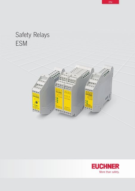
Internationally successful – the <strong>EUCHNER</strong> companyHeadquarters in Leinfelden-Echterdingen<strong>EUCHNER</strong> <strong>GmbH</strong> + <strong>Co</strong>. <strong>KG</strong> is a world-leading company in the area of industrial safetytechnology. <strong>EUCHNER</strong> has been developing and producing high-quality switching systemsfor mechanical and systems engineering for more than 50 years.The medium-sized family-operated company based in Leinfelden, Germany, employsmore than 500 people around the world, 400 in Germany alone.In addition to the production locations in Unterböhringen and Shanghai/China, 14 subsidiariesand other sales partners in Germany and abroad work for our internationalsuccess on the market.Quality and innovation – the <strong>EUCHNER</strong> productsLogistics center in Leinfelden-EchterdingenA look into the past shows <strong>EUCHNER</strong> to be a company with a great inventive spirit.We take the technological and ecological challenges of the future as an incentive forextraordinary product developments.<strong>EUCHNER</strong> safety switches monitor safety doors on machines and installations, help tominimize dangers and risks and thereby reliably protect people and processes. Today,our products range from electromechanical and electronic components to intelligentintegrated safety solutions. <strong>Safety</strong> for people, machines and products is one of ourdominant themes.Production location in UnterböhringenmadeinGermanyWe defi ne future safety technology with the highest quality standards and reliabletechnology. Extraordinary solutions ensure the great satisfaction of our customers.The product ranges are subdivided as follows:Transponder-coded <strong>Safety</strong> Switches (CES)Transponder-coded <strong>Safety</strong> Switches with guard locking (CET)Interlocking and guard locking systems (Multifunctional Gate Box MGB)Access management systems (Electronic-Key-System EKS)Electromechanical <strong>Safety</strong> SwitchesMagnetically coded <strong>Safety</strong> Switches (CMS)Enabling Switches<strong>Safety</strong> <strong>Relays</strong>Emergency Stop DevicesHand-Held Pendant Stations and Handwheels<strong>Safety</strong> Switches with AS-InterfaceJoystick SwitchesPosition Switches2
<strong>Co</strong>ntents<strong>Safety</strong> <strong>Relays</strong> <strong>ESM</strong>General information 4The <strong>ESM</strong> modular principle 4Approvals 4Explanation of symbols 4<strong>Safety</strong> relays <strong>ESM</strong> 7<strong>Safety</strong> relay <strong>ESM</strong>-BL.. and <strong>ESM</strong>-BA.. 8<strong>Safety</strong> relay time-delayed <strong>ESM</strong>-BT.. 12<strong>Safety</strong> relay 2-hand <strong>ESM</strong>-2H.. 13<strong>Co</strong>ntact expansion <strong>ESM</strong>-ES.. 14<strong>Co</strong>ntact expansion time-delayed <strong>ESM</strong>-TE.. 15Accessories 16Technical data 17Appendix 26Glossary 26<strong>Co</strong>nnection examples 26Item index 29110651-05-02/133
<strong>Safety</strong> <strong>Relays</strong> <strong>ESM</strong>General informationFor machines and systems that can produce a risk for people when inoperation, the EU Machinery directive defines minimum requirements thatare intended to reduce to a minimum the specific hazards and the relatedrisks of accident.If all sources of danger cannot be eliminated by design measures, appropriateprotective measures must be taken. Using safety guards, suchas fences or similar, it is intended to prevent people entering the dangerarea. If users need to have access to the danger area during operation,movable safety guards such as safety doors, flaps, etc, are used. This isthe case, for example, for loading or unloading, troubleshooting, machinesetup or cleaning work.To safeguard this access area, safety switches with various principles ofoperation are used. These switches are designed to monitor the positionof the safety guard and, when the safety guard is opened, to generatea signal which will safely interrupt the supply of power to the potentiallyhazardous parts of the system or which will ensure that the safety circuitsare safely interrupted. The <strong>EUCHNER</strong> safety relays series <strong>ESM</strong> ensure thatthe safety circuits are interrupted. On the one hand they safely evaluatecomponents connected such asApprovalsTo demonstrate conformity, the Machinery Directive also includes thepossibility of type examination. Although all relevant standards are takeninto account during development, we have all our switchgear subjectedto additional type examinations by a notified body.Furthermore, numerous items of switchgear are listed by UnderwritersLaboratories (UL). These items of switchgear can be used in countries inwhich this listing is required. The approval symbols on the individual pagesof the catalog indicate which body tested the switchgear.With the aid of the approval symbols listed below you can quickly seewhich approvals are available for the related switchgear:Switches with this symbol are approved byUnderwriters Laboratories (UL)Switches with this symbol are approved byTÜV Rheinlandffffffffmechanical safety switches with and without guard locking,non-contact safety switches,emergency stop controlsnon-contact protective equipment, etc.Explanation of symbols<strong>Co</strong>nnection optionswhile on the other hand they safely shut down potentially hazardousmachine functions.The safety relays impress with their compact DIN rail housing and theirsuitability for applications up to safety category 4/PLe in accordancewith EN ISO 13849‐1.STOPSuitable for the connectionof emergency stopSuitable for the connection of safetyswitches according to EN 1088The <strong>ESM</strong> modular principleThe majority of modules in the safety relay series <strong>ESM</strong> are installed in ahousing that is only 22.5 mm wide. Various safety relays are available towhich contact expansions can be added on the output side. The contactexpansions can be non-time-delay or time-delayed. The advantage of thismodular principle is that only a few devices are required to be able torealize a large number of different safety evaluations.The relays can be operated with various types of starting. The devicescan be started manually or automatically using suitable wiring. The manualstart can also monitor the start button.Using suitable wiring it is also possible to integrate a feedback loop suchthat safety-related parts of a machine or system downstream can alsobe monitored.In the <strong>ESM</strong> series the majority of the devices are available with a varietyof input voltage ranges.Fault detectionSuitable for the connection of non-contactprotective equipment, e. g. light curtainsSuitable for the connectionof 2-hand circuitsShort circuit is detectedGround fault is detectedEarth fault is detectedTime-delay<strong>Safety</strong> contacts switch time-delayed4Subject to technical modifications; no responsibility is accepted for the accuracy of this information.
<strong>Safety</strong> <strong>Relays</strong> <strong>ESM</strong><strong>Safety</strong> categoryCat.3Suitable up to category 3 according toEN ISO 13849‐1Cat.4Suitable up to category 4 according toEN ISO 13849‐1Stop categorySTOP0Immediate shutdownStop category 0 according to EN 60204-1STOP1Time-delayed shutdownStop category 1 according to EN 60204-1Technical dataMechanical dataElectrical dataSubject to technical modifications; no responsibility is accepted for the accuracy of this information.5
<strong>Safety</strong> <strong>Relays</strong> <strong>ESM</strong>6Subject to technical modifications; no responsibility is accepted for the accuracy of this information.
<strong>Safety</strong> relay <strong>ESM</strong>Selection table for safety relays <strong>ESM</strong><strong>Safety</strong> relaysBL Non-time-delay category 3BA Non-time-delay category 4BT Time-delay category 3/non-time delay category 42H 2-hand requirement level IIIC according to EN 574, category 4<strong>Co</strong>ntact expansionES Non-time-delay category 4TE Time-delay category 4Category according to EN ISO 13849‐1K Category according to EN ISO 13849‐1Enable pathSUSVM<strong>Safety</strong> contacts non-time-delay<strong>Safety</strong> contacts time-delayMonitored Start buttonRelay startAMUAutomatic startStart buttonMonitored Start buttonMonitoringRQEMFeedback loopShort circuitmonitoringEarth faultmonitoringGround faultmonitoringDevices Outputs Start MonitoringPageBL BA BT 2H ES TE K SU SV M A M U R Q E M● 3 2 ● ● ● 8● 4 2 ● ● ● ● ● ● ● 9● 4 3 1 ● ● ● ● ● ● ● 10● 4 7 4 ● ● ● ● ● ● ● 11● 4/3 1 3 ● ● ● ● ● ● ● 12● 4/3 2 2 ● ● ● ● ● ● ● 12● 4/3 3 1 ● ● ● ● ● ● ● 12● 4 2 ● ● ● ● ● 13● 4 3 1 ● ● 14● 3 3 1 ● ● 157
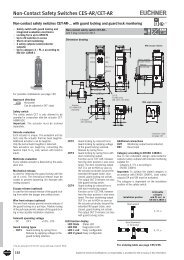
<strong>Safety</strong> <strong>Relays</strong> <strong>ESM</strong><strong>Safety</strong> relays <strong>ESM</strong>‐BL.. and <strong>ESM</strong>‐BA..ff<strong>ESM</strong>‐BL.. Usage up to category 3according to EN ISO 13849‐1ff<strong>ESM</strong>‐BA.. Usage up to category 4according to EN ISO 13849‐1ffLED status indicatorsff1-channel or 2-channel controlffUp to 7 redundant safety contactsffAuxiliary contact (signaling contact)optionalffShort circuit and earth fault/groundfault monitoring optional<strong>Safety</strong> relay <strong>ESM</strong>‐BL..STOPDimension drawingSuitable for 35 mm DIN railto DIN EN 60715 TH 35Cat.3STOP0A1 13 23 S219913 23K1K214 24<strong>ESM</strong>-BL2S11 14 24 A2Relay outputsThe outputs are electrically decoupled and ofredundant design.<strong>Co</strong>nnection optionsBy using suitable wiring the following functionscan be selected:ffRelay start with automatic start or a startbuttonffMonitoring of downstream relays or contactorsOn the series <strong>ESM</strong>‐BA.. safety relays, by usingsuitable wiring it is also possible to select:ffSimultaneity monitoring to monitor safetycomponents over timeffShort circuit monitoring to detect short circuitsbetween the connection cables and to shutdown the outputs or prevent relay starting ifnecessaryffEarth fault/ground fault monitoring to detectshort circuits between the connection cablesand earth or ground and to shut down theoutputs or prevent relay starting if necessary.Auxiliary contactsThe relays in the series <strong>ESM</strong>‐BA3.. and <strong>ESM</strong>‐BA7...are available with electrically separate normallyclosed contacts and auxiliary contacts.<strong>Co</strong>nnection terminalsOptionally the <strong>ESM</strong>‐BA... devices are also availableas version with plug-in connection terminals.Block diagramTechnical data outputsParameterMin. switching current at DC 24 VSwitching voltage max.Utilization category *According to EN 60947-5-122,5 114A1 A2~ - -PowersupplyS21 S11StartInputsU e = switching voltageI e = max. switching current per contactΣ I e = max. switching current on all safety contacts (cumulative current)* See page 26 for information about the utilization categoryK1K213142324Value20 mADC 24 V / AC 250 VU e I e Σ I eAC-12 250 V 6 AAC-15 230 V 4 A12 ADC-12 24 V 1.25 ADC-13 24 V 2 AOrdering tableSeries Version Outputs AC/DC 24 V AC 115 V AC 230 V<strong>ESM</strong>BL<strong>Safety</strong> relay22 NO085607<strong>ESM</strong>‐BL201085608<strong>ESM</strong>‐BL202085609<strong>ESM</strong>‐BL2038Subject to technical modifications; no responsibility is accepted for the accuracy of this information.
<strong>Safety</strong> <strong>Relays</strong> <strong>ESM</strong><strong>Safety</strong> relay <strong>ESM</strong>‐BA2..STOPCat.4STOP0Dimension drawing<strong>ESM</strong>‐BA2...Suitable for 35 mm DIN railto DIN EN 60715 TH 35<strong>ESM</strong>‐BA201PPlug-in connection terminalsplease order separately13 23A1 S11 S14 S2113 23A1 S11 S14 S219913 23K1K214 249913 23K1K214 24K2<strong>ESM</strong>-BA2S12 S13 S10 A214 24K1<strong>ESM</strong>-BA2S12 S13 S10 A214 2422,511422,5Block diagramA1 A2S21 S10 S11 S12 S13 S141323~ - -StartInputsK1PowersupplyK21424Technical data outputsParameterMin. switching current at DC 24 VSwitching voltage max.Utilization category *According to EN 60947-5-1U e = switching voltageI e = max. switching current per contactΣ I e = max. switching current on all safety contacts (cumulative current)* See page 26 for information about the utilization categoryValue20 mADC 24 V / AC 250 VU e I e Σ I eAC-12 250 V 6 AAC-15 230 V 4 A12 ADC-12 24 V 1.25 ADC-13 24 V 2 AOrdering tableSeries Version Outputs Version AC/DC 24 V AC 115 V AC 230 V<strong>ESM</strong>BA<strong>Safety</strong> relay1) Please order plug-in connection terminals separately (see page 16)22 NO085610Screw terminals<strong>ESM</strong>‐BA201Plug-in097226connection terminals 1) <strong>ESM</strong>‐BA201P085611<strong>ESM</strong>‐BA202085612<strong>ESM</strong>‐BA203- -For technical data see page 17Subject to technical modifications; no responsibility is accepted for the accuracy of this information.9
<strong>Safety</strong> <strong>Relays</strong> <strong>ESM</strong><strong>Safety</strong> relay <strong>ESM</strong>‐BA3..STOPCat.4STOP0Dimension drawing<strong>ESM</strong>‐BA3...Suitable for 35 mm DIN railto DIN EN 60715 TH 35Plug-in connection terminalsplease order separately<strong>ESM</strong>‐BA301P13 23 33 41A1 S11 S14 S2113 23 33 41A1 S11 S14 S219913 23 33 41K1K214 24 34 429913 23 33 41K1K214 24 34 42K2<strong>ESM</strong>-BA3S12 S13 S10 A214 24 34 42K1<strong>ESM</strong>-BA3S12 S13 S10 A214 24 34 4222,511422,5 114Block diagramA1 A2S21 S10 S11 S12 S13 S14 13 23 33 41~ - -StartInputsK1PowersupplyK214243442Technical data outputsParameterMin. switching current at DC 24 VSwitching voltage max.Utilization category *According to EN 60947-5-1Value5 mADC 24 V / AC 250 VU e I e Σ I eAC-12 250 V 8 AAC-15 250 V 3 ADC-12 50 V 8 A15 A 1)DC-13 24 V 3 A1) If several <strong>ESM</strong>‐BA3.. are closely spaced under load, the max. cumulative current at an ambient temperature of 20 °C = 9 A; at 30 °C = 3 A; at 40 °C = 1 A. If these currents are exceeded, aspacing of 5 mm between the devices must be observed.U e = switching voltageI e = max. switching current per contactΣ I e = max. switching current on all safety contacts (cumulative current)* See page 26 for information about the utilization categoryOrdering tableSeries Version Outputs Version AC/DC 24 V AC 115 V AC 230 V<strong>ESM</strong>BA<strong>Safety</strong> relay1) Please order plug-in connection terminals separately (see page 16)33 NO + 1 NC085613Screw terminals<strong>ESM</strong>‐BA301Plug-in097230connection terminals 1) <strong>ESM</strong>‐BA301P087412<strong>ESM</strong>‐BA302087413<strong>ESM</strong>‐BA303- -10Subject to technical modifications; no responsibility is accepted for the accuracy of this information.
<strong>Safety</strong> <strong>Relays</strong> <strong>ESM</strong><strong>Safety</strong> relay <strong>ESM</strong>‐BA7..STOPCat.4STOP0Dimension drawingPlug-in connection terminalsplease order separately13 23 33 81S21 S11 S14 9143 53 63 73101 O1 O2 A19913 23 33 81 91 43 53 6373101K1K214 24 34 82 92 44 546474 102 112PwrK1K2S12 S13 S10 9214 24 34 82<strong>ESM</strong>-BA701102 112 0V A244 54 64 7445 114Suitable for 35 mm DIN railto DIN EN 60715 TH 35Block diagramA1 A2S21 S10 S11 S12 S13 S14 13 23 33819143536373101~ - -StartInputsK1PowersupplyMonitoringoutputsK20VO1O2142434 829244546474 102 112Technical data outputsParameterMin. switching current at DC 24 VSwitching voltage max.Utilization category *According to EN 60947-5-11) With a housing distance of 10 mm. 20 A closely spaced at 40 °CValue5 mADC 50 V / AC 250 VU e I e Σ I eAC-12 250 V 8 AAC-15 250 V 3 ADC-12 50 V 8 A35 A 1)DC-13 24 V 3 AU e = switching voltageI e = max. switching current per contactΣ I e = max. switching current on all safety contacts (cumulative current)* See page 26 for information about the utilization categoryOrdering tableSeries Version Outputs Version AC/DC 24 V AC 115 V AC 230 V<strong>ESM</strong>BA<strong>Safety</strong> relay77 NO + 4 NCPlug-inconnection terminals 1) 097225<strong>ESM</strong>‐BA701P1) Please order plug-in connection terminals separately (see page 16). Two connection kits are required for devices from series <strong>ESM</strong>‐BA701P.- -For technical data see page 17Subject to technical modifications; no responsibility is accepted for the accuracy of this information.11
<strong>Safety</strong> <strong>Relays</strong> <strong>ESM</strong><strong>Safety</strong> relays <strong>ESM</strong>‐2H..ffUsage up to category 4 accordingto EN ISO 13849-1ffRequirement level IIIC accordingto EN 574ffLED status indicatorsffOperation using 2-hand controlff2 redundant safety contactsffShort-circuit and earth fault/groundfault monitoring can be selected<strong>Safety</strong> relay <strong>ESM</strong>‐2H..Dimension drawingSuitable for 35 mm DIN railto DIN EN 60715 TH 35Cat.4STOP0X1 X2 13 23A1 S11 S12 S139913 23K1K214 24<strong>ESM</strong>-2H2S21 S22 S23 A214 24Relay outputsThe outputs are electrically decoupled and ofredundant design.<strong>Co</strong>nnectionffTwo buttons each with one normally closedcontact and one normally open contact thatare monitored for simultaneity according toEN 574. In this way a high level of protectionagainst tampering is provided.ffShort circuit monitoring to detect short circuitsbetween the connection cables and to shutdown the outputs or prevent relay starting ifnecessary.ffEarth fault/ground fault monitoring to detectshort circuits between the connection cablesand earth or ground and to shut down theoutputs or prevent relay starting if necessary.Block diagram22,5 114A1 A2~ - -PowersupplyS11 S12 S13 S21 S22 S23X1Channel 1 Channel 2InputsFeedbackloopX2K1K213142324<strong>Co</strong>nnection optionBy using suitable wiring the following functioncan be selected:ffMonitoring of downstream relays or contactorsTechnical data outputsParameterMin. switching current at DC 24 VSwitching voltage max.Utilization category *According to EN 60947-5-1U e = switching voltageI e = max. switching current per contactΣ I e = max. switching current on all safety contacts (cumulative current)* See page 26 for information about the utilization categoryValue20 mADC 24 V / AC 250 VU e I e Σ I eAC-12 250 V 6 AAC-15 230 V 4 A8.4 ADC-12 24 V 1.25 ADC-13 24 V 2 AOrdering tableSeries Version Outputs AC/DC 24 V AC 115 V AC 230 V<strong>ESM</strong>2H<strong>Safety</strong> relay22 NO085620<strong>ESM</strong>‐2H201098345<strong>ESM</strong>‐2H202-For technical data see page 17Subject to technical modifications; no responsibility is accepted for the accuracy of this information.13
<strong>Safety</strong> <strong>Relays</strong> <strong>ESM</strong><strong>Co</strong>ntact expansion <strong>ESM</strong>‐ES..ffUsage up to category 4 according toEN ISO 13849-1ffLED status indicatorsff<strong>Co</strong>ntrol using safety relaysff3 redundant safety contactsff1 door auxiliary contactffEarth fault/ground fault monitoring canbe selected<strong>Co</strong>ntact expansion <strong>ESM</strong>‐ES..Dimension drawingCat.4STOP0Suitable for 35 mm DIN railto DIN EN 60715 TH 3513 23 33A1 S11 S15 S169913 23 33 S23K1K214 24 34 S24<strong>ESM</strong>-ES3S23 S24 S10 A214 24 34Relay outputsThe outputs are electrically decoupled and ofredundant design.22,5 114<strong>Co</strong>nnection optionBy using suitable wiring the following functioncan be selected:ffEarth fault/ground fault monitoring to detectshort circuits between the connection cablesand earth or ground and to shut down theoutputs or prevent relay starting if necessary.Block diagramA1 A2~ - -S10 S11 S15 S16 S23 13 23 33Inputs K1PowersupplyK2S24142434Technical data outputsParameterMin. switching current at DC 24 VSwitching voltage max.Utilization category *According to EN 60947-5-1U e = switching voltageI e = max. switching current per contactΣ I e = max. switching current on all safety contacts (cumulative current)* See page 26 for information about the utilization categoryValue5 mADC 50 V / AC 250 VU e I e Σ I eAC-12 250 V 6 AAC-15 230 V 4 A10.5 ADC-12 24 V 1.25 ADC-13 24 V 2 AOrdering tableSeries Version Outputs AC/DC 24 V AC 115 V AC 230 V<strong>ESM</strong>ES<strong>Co</strong>ntact expansion33 NO + 1 NC085614<strong>ESM</strong>‐ES301085615<strong>ESM</strong>‐ES302085616<strong>ESM</strong>‐ES30314Subject to technical modifications; no responsibility is accepted for the accuracy of this information.
<strong>Safety</strong> <strong>Relays</strong> <strong>ESM</strong><strong>Co</strong>ntact expansion <strong>ESM</strong>‐ES..ffUsage up to category 3 according toEN ISO 13849-1ffLED status indicatorsff<strong>Co</strong>ntrol using safety relaysff3 redundant time-delayed safety contactsffTime-delay range between 1 s and 30 sffFixed time delay of 0.5 s optionalff1 auxiliary contactffEarth fault/ground fault monitoring canbe selected<strong>Co</strong>ntact expansion <strong>ESM</strong>‐ES..Dimension drawingSuitable for 35 mm DIN railto DIN EN 60715 TH 35Cat.3STOP117 27 37A1 S11 S15 S169917 27 37 S25K1K218 28 38 S26t<strong>ESM</strong>-TE3S25 S26 S10 A218 28 38Relay outputsThe outputs are electrically decoupled and ofredundant design.22,5 114<strong>Co</strong>nnection optionBy using suitable wiring the following functioncan be selected:ffEarth fault/ground fault monitoring to detectshort circuits between the connection cablesand earth or ground and to shut down theoutputs or prevent relay starting if necessary.Block diagramA1 A2S10 S11 S15 S16 S25 17 27 37Inputs K1Time-delayed shutdownThe release time for the time-delay contacts canbe set as required using a potentiometer on thesafety relay.~ - -PowersupplyK2S26182838Technical data outputsParameterMin. switching current at DC 24 VSwitching voltage max.Utilization category *According to EN 60947-5-1U e = switching voltageI e = max. switching current per contactΣ I e = max. switching current on all safety contacts (cumulative current)* See page 26 for information about the utilization categoryValue5 mADC 50 V / AC 250 VU e I e Σ I eAC-12 250 V 6 AAC-15 250 V 4 A10.5 ADC-12 24 V 1.25 ADC-13 24 V 2 AOrdering tableSeries Version Outputs Time-delay AC/DC 24 V AC 115 V AC 230 V<strong>ESM</strong>TE<strong>Co</strong>ntact expansion33 NO + 1 NC timedelayedAdjustable1 s ... 30 sFixed0.5 s085617<strong>ESM</strong>‐TE301097223<strong>ESM</strong>‐TE301-05S085618<strong>ESM</strong>‐TE302085619<strong>ESM</strong>‐TE303- -For technical data see page 17Subject to technical modifications; no responsibility is accepted for the accuracy of this information.15
AccessoriesAccessories for <strong>Safety</strong> System <strong>ESM</strong>ff<strong>Co</strong>nnection kit <strong>ESM</strong>...P with screw terminals or spring terminalsImportant: One connection kit is required, depending on the device (see information on the corresponding product page). Two connection kits arerequired for devices from series <strong>ESM</strong>-BA701P.Ordering tableDesignation Description Order No.<strong>Co</strong>nnection kit<strong>ESM</strong>...Pwith screw terminals<strong>Co</strong>nnection kit<strong>ESM</strong>...Pwith spring terminals<strong>Co</strong>mprising:4 plug-in screw terminals (can be coded)2 jumperscoding pins<strong>Co</strong>mprising:4 plug-in spring terminals (can be coded)2 jumperscoding pins097194<strong>ESM</strong>-F-AK4097195<strong>ESM</strong>-F-KK416Subject to technical modifications; no responsibility is accepted for the accuracy of this information.
Technical DataOverview safety relays <strong>ESM</strong><strong>Safety</strong> relays <strong>ESM</strong>BL Non-time-delay category 3BA Non-time-delay category 4BT Time-delay category 3/non-time delay category 42H 2-hand requirement level IIIC according to EN 574, category 4<strong>Co</strong>ntact expansion <strong>ESM</strong>ES Non-time-delay category 4TE Time-delay category 4<strong>Safety</strong> relay <strong>ESM</strong>PageBL BA BT 2H ES TE● 18● 19● 22● 23● 24● 2517
Technical Data <strong>Safety</strong> Relay <strong>ESM</strong>HousingParameter Value UnitHousing materialPolyamide PA6.6Dimensions 114 x 99 x 22.5 (<strong>ESM</strong>-BA7... 114 x 99 x 45) mmWeight Approx. 0.25 (<strong>ESM</strong>-BA7... approx. 0.35) kg<strong>Co</strong>nnection<strong>Co</strong>nnection terminals<strong>Co</strong>nnection terminals 0.14 … 2.5 mm 2Ambient temperature Base <strong>ESM</strong>-BL2.. <strong>ESM</strong>-BA2.. <strong>ESM</strong>-BA3.. <strong>ESM</strong>-BA7.. <strong>ESM</strong>-BT4.. <strong>ESM</strong>-2H2..at U B = 24 V DC -15 ... +60 -15 … +40 -15 … +40 -15 ... +60 °Cat U B = 115/230 V AC -15 ... +40 -15 ... +40 - -15 ... +40 °C<strong>Co</strong>ntact expansion<strong>ESM</strong>-ES3.. <strong>ESM</strong>-TE3…at U B = 24 V DC -15 … +60 °Cat U B = 115/230 V AC -15 ... +40 °CDegree of protection according to EN 60529 IP 20Degree of contamination 2Mounting DIN rail 35 mm according to DIN EN 60715 TH 35Life Base <strong>ESM</strong>-BL2.. <strong>ESM</strong>-BA2..<strong>ESM</strong>-BA3..<strong>ESM</strong>-BA7.. <strong>ESM</strong>-BT4.. <strong>ESM</strong>-2H2..Mechanical 1 x 10 7 1 x 10 6 1 x 10 6 1 x 10 7 operating cyclesElectrical 1 x 10 5 1 x 10 6 1 x 10 5 1 x 10 5 operating cycles<strong>Co</strong>ntact expansion<strong>ESM</strong>-ES3.. <strong>ESM</strong>-TE3…Mechanical 1 x 10 7 operating cyclesElectrical 1 x 10 5 operating cycles<strong>Co</strong>nnection <strong>ESM</strong>-BL2..Parameter Value UnitOperating voltage <strong>ESM</strong>-BL201 24 ± 10% 1) V AC/DC<strong>ESM</strong>-BL202 115 ± 10% V AC<strong>ESM</strong>-BL203 230 ± 10% V ACReverse polarity protectionOn <strong>ESM</strong>-BL201Rated supply frequency 50 ... 60 HzPower consumptionApprox. 3 VA / 1.8 W<strong>Co</strong>ntrol voltage for start button 18.6 … 26 V DC<strong>Co</strong>ntrol cable length (cross-section 0.75 mm²) Max. 1000 m<strong>Co</strong>ntrol current for start button Approx. 40 mAExternal contact fuse (safety circuit) acc. to EN IEC 60269-110 A gG (T4A / F6A)Test voltage (control voltage/contacts) 2.5 kVRated impulse withstand voltage,Leakage path and air gaps acc. to DIN VDE 0110-14 kVRated insulation voltage 250 VOver voltage category according to DIN VDE 0110-1 3<strong>Safety</strong> contacts2 NO contacts (redundant)Min. switching current at 24 V DC 20 mASwitching voltage max. 24 V DC250 V ACBreaking capacity acc. to6 A 250 V AC2 A 24 V DCUtilization category 2)U e I e Σ I eAccording to EN 60947-5-1AC-12 250 V 6 AAC-15 230 V 4 ADC-12 24 V 1.25 A12 ADC-13 24 V 2 ALED indicators2, status display for relays K1 and K2Reliability values acc. to EN ISO 13849‐1Category 3Performance Level PLd1) All the electrical connections must either be isolated from the mains supply by a safety transformer according to EN 61558-2-6 with limited output voltage in the event of a fault, or by otherequivalent isolation measures.2) See page 26 for information about the utilization category.U e = switching voltage I e = max. switching current per contact Σ I e = max. switching current on all safety contacts (cumulative current)18Subject to technical modifications; no responsibility is accepted for the accuracy of this information.
Technical Data <strong>Safety</strong> Relay <strong>ESM</strong><strong>Co</strong>nnection <strong>ESM</strong>-BA2..Parameter Value UnitOperating voltage <strong>ESM</strong>-BA201 24 ± 10% 1) V AC/DC<strong>ESM</strong>-BA202 115 ± 10% V AC<strong>ESM</strong>-BA203 230 ± 10% V ACReverse polarity protectionOn <strong>ESM</strong>-BA201Rated supply frequency 50 ... 60 HzPower consumptionApprox. 3 VA / 1.8 W<strong>Co</strong>ntrol voltage for start button 18.6 … 26 V DC<strong>Co</strong>ntrol cable length (cross-section 0.75 mm²) Max. 1000 m<strong>Co</strong>ntrol current for start button Approx. 40 mAExternal contact fuse (safety circuit) acc. to EN IEC 60269-110 A gG (T4A / F6A)Test voltage (control voltage/contacts) 2.5 kVRated impulse withstand voltage,Leakage path and air gaps acc. to DIN VDE 0110-14 kVRated insulation voltage 250 VOver voltage category according to DIN VDE 0110-1 3<strong>Safety</strong> contacts2 NO contacts (redundant)Min. switching current at 24 V DC 20 mASwitching voltage max. 24 V DC250 V ACBreaking capacity acc. to6 A 250 V AC2 A 24 V DCUtilization category 2)U e I e Σ I eAccording to EN 60947-5-1AC-12 250 V 6 AAC-15 230 V 4 ADC-12 24 V 1.25 A12 ADC-13 24 V 2 ALED indicators2, status display for relays K1 and K2Reliability values acc. to EN ISO 13849‐1Category 4Performance Level PLe1) All the electrical connections must either be isolated from the mains supply by a safety transformer according to EN 61558-2-6 with limited output voltage in the event of a fault, or by otherequivalent isolation measures.2) See page 26 for information about the utilization category.U e = switching voltage I e = max. switching current per contact Σ I e = max. switching current on all safety contacts (cumulative current)Subject to technical modifications; no responsibility is accepted for the accuracy of this information.19
Technical Data <strong>Safety</strong> Relay <strong>ESM</strong><strong>Co</strong>nnection <strong>ESM</strong>-BA3..AC-12 V 8 4)Parameter Value UnitOperating voltage <strong>ESM</strong>-BA301 24 ± 10% 1) V AC/DC<strong>ESM</strong>-BA302 115 ± 10% V AC<strong>ESM</strong>-BA303 230 ± 10% V ACReverse polarity protectionOn <strong>ESM</strong>-BA301Rated supply frequency 50 ... 60 HzPower consumption Approx. 7 VA<strong>Co</strong>ntrol voltage for start button 18.6 … 26 V DC<strong>Co</strong>ntrol cable length (cross-section 0.75 mm²) Max. 1000 m<strong>Co</strong>ntrol current for start button Approx. 60 mAExternal contact fuse (safety circuit) acc. to EN IEC 60269-110 A gG (T6A / F8A)Test voltage (control voltage/contacts) 2.5 kVRated impulse withstand voltage,Leakage path and air gaps acc. to DIN VDE 0110-14 kVRated insulation voltage 250 VOver voltage category according to DIN VDE 0110-1 3<strong>Safety</strong> contacts3 NO contacts (redundant)Cumulative current on all contacts acc. to Max. 15 AMin. switching current at 24 V DC 5 mASwitching voltage max. 50 V DC250 V ACBreaking capacity acc. to <strong>ESM</strong>-BA301 8 A 250 V AC / 2 A 24 V DC<strong>ESM</strong>-BA302<strong>ESM</strong>-BA3038 A 250 V AC / 3 A 24 V DCUtilization category 2)U e I e Σ I eAccording to EN 60947-5-1250 AAC-15 250 V 3 ADC-12 50 V 8 A 4)15 A 3)DC-13 24 V 3 ALED indicators2, status display for relays K1 and K2Signaling contact1 NC contactSwitching voltage max. 24 V DC250 V ACBreaking capacity acc. to <strong>ESM</strong>-BA301 2 A 250 V AC / 1.5 A 24 V DC<strong>ESM</strong>-BA302<strong>ESM</strong>-BA3032 A 250 V AC / 2 A 24 V DCUtilization category 2)According to EN 60947-5-1U eAC-12 250 V 2 AAC-15 250 V 1.5 ADC-12 50 V 2 ADC-13 24 V 1.25 AReliability values acc. to EN ISO 13849‐1Category 4Performance Level PLe1) All the electrical connections must either be isolated from the mains supply by a safety transformer according to EN 61558-2-6 with limited output voltage in the event of a fault, or by otherequivalent isolation measures.2) See page 26 for information about the utilization category.3) If several <strong>ESM</strong>-BA3.. are closely spaced under load, the max. cumulative current at an ambient temperature of 20 °C = 9 A; at 30 °C = 3 A; at 40 °C = 1 A. If these currents are exceeded, aspacing of 5 mm between the devices must be observed.4) With Ohmic load.U e = switching voltage I e = max. switching current per contact Σ I e = max. switching current on all safety contacts (cumulative current)I e20Subject to technical modifications; no responsibility is accepted for the accuracy of this information.
Technical Data <strong>Safety</strong> Relay <strong>ESM</strong><strong>Co</strong>nnection <strong>ESM</strong>-BA7..Parameter Value UnitOperating voltage 24 ± 10% 1) V AC/DCReverse polarity protectionYesRated supply frequency 50 ... 60 HzPower consumption Approx. 7 VA<strong>Co</strong>ntrol voltage for start button 18.6 … 26 V DC<strong>Co</strong>ntrol cable length (cross-section 0.75 mm²) Max. 1000 m<strong>Co</strong>ntrol current for start button Approx. 100 mAExternal contact fuse (safety circuit) acc. to EN IEC 60269-110 A gG (T6A / F8A)Test voltage (control voltage/contacts) 2.5 kVRated impulse withstand voltage,Leakage path and air gaps acc. to DIN VDE 0110-14 kVRated insulation voltage 250 VOver voltage category according to DIN VDE 0110-1 3<strong>Safety</strong> contacts7 NO contacts (redundant)Min. switching current at 24 V DC 5 mASwitching voltage max. 50 V DC250 V ACBreaking capacity acc. to (per contact) 8 A 250 V AC2 A 24 V DCUtilization category 2)U e I e Σ I eAccording to EN 60947-5-1AC-12 250 V 8 AAC-15 250 V 3 ADC-12 50 V 8 A35 A 3)DC-13 24 V 3 ALED indicators2, status display for relays K1 and K2Auxiliary contacts4 NC contactsSwitching voltage max. 50 V DC250 V ACBreaking capacity acc. to2 A 250 V AC1.5 A 24 V DCUtilization category 2)U eI eAccording to EN 60947-5-1AC-12 250 V 8 AAC-15 250 V 3 ADC-12 50 V 8 ADC-13 24 V 3 ADoor monitoring outputs2 semiconductor outputsSemiconductor output current Max. 30 mASemiconductor output voltage 24 V DCReliability values acc. to EN ISO 13849‐1Category 4Performance Level PLe1) All the electrical connections must either be isolated from the mains supply by a safety transformer according to EN 61558-2-6 with limited output voltage in the event of a fault, or by otherequivalent isolation measures.2) See page 26 for information about the utilization category.3) With a housing distance of 10 mm. 20 A closely spaced at 40 °C.U e = switching voltage I e = max. switching current per contact Σ I e = max. switching current on all safety contacts (cumulative current)Subject to technical modifications; no responsibility is accepted for the accuracy of this information.21
Technical Data <strong>Safety</strong> Relay <strong>ESM</strong><strong>Co</strong>nnection <strong>ESM</strong>-BT4..AC-12 V 8 4)Parameter Value UnitOperating voltage 24 ± 10% 1) V AC/DCReverse polarity protectionYesRated supply frequency 50 ... 60 HzPower consumption Approx. 4.6 WTime-delay range 1 ... 30 s<strong>Co</strong>ntrol voltage for start button 18.6 … 26 V DC<strong>Co</strong>ntrol cable length (cross-section 0.75 mm²) Max. 1000 m<strong>Co</strong>ntrol current for start button Approx. 190 mAExternal contact fuse (safety circuit) acc. to EN IEC 60269-110 A gG (T6A / F8A)Test voltage (control voltage/contacts) 2.5 kVRated impulse withstand voltage,Leakage path and air gaps acc. to DIN VDE 0110-14 kVRated insulation voltage 250 VOver voltage category according to DIN VDE 0110-1 3<strong>Safety</strong> contacts4 NO contacts (redundant)Cumulative current on all contacts acc. to Max. 15 AMin. switching current at 24 V DC 5 mASwitching voltage max. 50 V DC250 V ACBreaking capacity acc. to (per contact) 6 A 250 V AC2 A 24 V DCUtilization category 2)U e I e Σ I eAccording to EN 60947-5-1250 AAC-15 250 V 3 ADC-12 50 V 8 A 4)15 A 3)DC-13 24 V 3 ALED indicators4, status display for relays K1 to K4Reliability values acc. to EN ISO 13849‐1Category4 (non-time-delayed) / 3 (time-delayed)Performance Level PLe1) All the electrical connections must either be isolated from the mains supply by a safety transformer according to EN 61558-2-6 with limited output voltage in the event of a fault, or by otherequivalent isolation measures.2) See page 26 for information about the utilization category.3) With a housing distance of 5 mm. 9 A closely spaced at 40 °C.4) With Ohmic load.U e = switching voltage I e = max. switching current per contact Σ I e = max. switching current on all safety contacts (cumulative current)22Subject to technical modifications; no responsibility is accepted for the accuracy of this information.
Technical Data <strong>Safety</strong> Relay <strong>ESM</strong><strong>Co</strong>nnection <strong>ESM</strong>-2H2..AC-12 V 6 3)Parameter Value UnitOperating voltage <strong>ESM</strong>-2H201 24 ± 10% 1) V AC/DC<strong>ESM</strong>-2H202 115 ± 10% V ACReverse polarity protectionOn <strong>ESM</strong>-2H201Rated supply frequency 50 ... 60 HzPower consumption Approx. 4 VA<strong>Co</strong>ntrol voltage on start buttons S12 - S13 and S22 - S23 18.6 … 26 V DC<strong>Co</strong>ntrol cable length (cross-section 0.75 mm²) Max. 1000 m<strong>Co</strong>ntrol current for both buttons Each 20 mAExternal contact fuse (safety circuit) acc. to EN IEC 60269-110 A gG (T4A / F6A)Test voltage (control voltage/contacts) 2.5 kVRated impulse withstand voltage,Leakage path and air gaps acc. to DIN VDE 0110-14 kVRated insulation voltage 250 VOver voltage category according to DIN VDE 0110-1 3<strong>Safety</strong> contacts2 NO contacts (redundant)Synchronization time Max. 0.5 sRelease time for the safety relay (response time) Max. 20 msMin. switching current at 24 V DC 20 mASwitching voltage max. 24 V DC250 V ACBreaking capacity acc. to6 A 250 V AC2 A 24 V DCUtilization category 2)U e I e Σ I eAccording to EN 60947-5-1250 AAC-15 230 V 4 ADC-12 24 V 1.25 A 3)8.4 ADC-13 24 V 2 ALED indicators2, status display for relays K1 and K2Reliability values acc. to EN ISO 13849‐1Category 4Performance Level PLe1) All the electrical connections must either be isolated from the mains supply by a safety transformer according to EN 61558-2-6 with limited output voltage in the event of a fault, or by otherequivalent isolation measures.2) See page 26 for information about the utilization category.3) With Ohmic load.U e = switching voltage I e = max. switching current per contact Σ I e = max. switching current on all safety contacts (cumulative current)Subject to technical modifications; no responsibility is accepted for the accuracy of this information.23
Technical Data <strong>Safety</strong> Relay <strong>ESM</strong><strong>Co</strong>nnection <strong>ESM</strong>-ES3..AC-12 V 6 3)Parameter Value UnitOperating voltage <strong>ESM</strong>-ES301 24 ± 10% 1) V AC/DC<strong>ESM</strong>-ES302 115 ± 10% V AC<strong>ESM</strong>-ES303 230 ± 10% V ACReverse polarity protectionOn <strong>ESM</strong>-ES301Rated supply frequency 50 ... 60 HzPower consumptionApprox. 4 VA / 2 W<strong>Co</strong>ntrol voltage at inputs 18.6 … 26 V DC<strong>Co</strong>ntrol cable length (cross-section 0.75 mm²) Max. 1000 mExternal contact fuse (safety circuit) acc. to EN IEC 60269-110 A gG (T4A / F6A)Test voltage (control voltage/contacts) 2.5 kVRated impulse withstand voltage,Leakage path and air gaps acc. to DIN VDE 0110-14 kVRated insulation voltage 250 VOver voltage category according to DIN VDE 0110-1 3Cumulative current on all contacts acc. to Max. 10.5 A<strong>Safety</strong> contacts3 NO contacts (redundant)Min. switching current at 24 V DC 20 mASwitching voltage max. 50 V DC250 V ACBreaking capacity acc. to (per contact) 6 A 250 V AC2 A 24 V DCUtilization category 2)U e I e Σ I eAccording to EN 60947-5-1250 AAC-15 230 V 4 ADC-12 24 V 1.25 A 3)10.5 ADC-13 24 V 2 ALED indicators2, status display for relays K1 and K2Auxiliary contact1 NC contact<strong>Co</strong>ntinuous current max. 500 4) mASwitching voltage max. 24 V AC/DCReliability values acc. to EN ISO 13849‐1Category 4Performance Level PLe1) All the electrical connections must either be isolated from the mains supply by a safety transformer according to EN 61558-2-6 with limited output voltage in the event of a fault, or by otherequivalent isolation measures.2) See page 26 for information about the utilization category.3) With Ohmic load.4) As monitoring contact for safety relay.U e = switching voltage I e = max. switching current per contact Σ I e = max. switching current on all safety contacts (cumulative current)24Subject to technical modifications; no responsibility is accepted for the accuracy of this information.
Technical Data <strong>Safety</strong> Relay <strong>ESM</strong><strong>Co</strong>nnection <strong>ESM</strong>-TE3..AC-12 V 6 4)Parameter Value UnitOperating voltage <strong>ESM</strong>-TE301 24 ± 10% 1) V AC/DC<strong>ESM</strong>-TE302 115 ± 10% V AC<strong>ESM</strong>-TE303 230 ± 10% V ACReverse polarity protectionOn <strong>ESM</strong>-TE301Rated supply frequency 50 ... 60 HzPower consumption Approx. 4 VATime-delay range 1 ... 30 sFixed time delay <strong>ESM</strong>-TE301-05S 0.5 2) s<strong>Co</strong>ntrol voltage at inputs 18.6 … 26 V DC<strong>Co</strong>ntrol cable length (cross-section 0.75 mm²) Max. 1000 mExternal contact fuse (safety circuit) acc. to EN IEC 60269-110 A gG (T4A / F6A)Test voltage (control voltage/contacts) 2.5 kVRated impulse withstand voltage,Leakage path and air gaps acc. to DIN VDE 0110-14 kVRated insulation voltage 250 VOver voltage category according to DIN VDE 0110-1 3Cumulative current on all contacts acc. to Max. 10.5 A<strong>Safety</strong> contacts3 NO contacts (redundant)Min. switching current at 24 V DC 20 mASwitching voltage max. 50 V DC250 V ACBreaking capacity acc. to (per contact) 6 A 250 V AC2 A 24 V DCUtilization category 3)U e I e Σ I eAccording to EN 60947-5-1250 AAC-15 250 V 4 ADC-12 24 V 1.25 A 4)10.5 ADC-13 24 V 2 ALED indicators2, status display for relays K1 and K2Auxiliary contact1 NC contact<strong>Co</strong>ntinuous current max. 500 5) mASwitching voltage max. 24 V DCReliability values acc. to EN ISO 13849‐1Category 3Performance Level PLd1) All the electrical connections must either be isolated from the mains supply by a safety transformer according to EN 61558-2-6 with limited output voltage in the event of a fault, or by otherequivalent isolation measures.2) On <strong>ESM</strong>‐TE301-05S the potentiometer is not required.3) See page 26 for information about the utilization category.4) With Ohmic load.5) As monitoring contact for safety relay.U e = switching voltage I e = max. switching current per contact Σ I e = max. switching current on all safety contacts (cumulative current)Subject to technical modifications; no responsibility is accepted for the accuracy of this information.25
AppendixGlossaryFeedback loop<strong>Co</strong>mponents connected downstream of the safety relay can be monitoredfor correct function. For this purpose normally closed contacts on thesecomponents are integrated into the feedback loop on the relay.<strong>Co</strong>nnection examples safety relay <strong>ESM</strong><strong>Safety</strong> relay <strong>ESM</strong>-BL..Automatic start without integration of the feedback loopRelay startAfter the relay has switched off due to a request from a safety componentconnected, the relay must be re-started. On this topic please pay attentionto section 5.2.2 of EN ISO 13849‐1:2008.ffAutomatic startThe relay switches on automatically as soon as the safety componentconnected changes back to the safe state.ffManual startThe relay is started by actuating a button. First the safe state of the safetycomponents connected must be re-established.ffMonitored, manual startThe relay is started by actuating a button. The button is monitored forjamming or possible tampering. Prior to starting the relay the safe stateof the safety components connected must be re-established.Single-channel safety circuitA single positively driven contact in the safety component is connectedto the relay. This connection is suitable for categories 1 or 2 accordingto EN ISO 13849‐1.S11 S21Manual start without integration of the feedback loopSS11 S21Automatic start with integration of the feedback loopDual-channel safety circuitTwo contacts of which at least one is a positively driven contact areconnected to the relay. This connection is suitable for categories 3 or 4according to EN ISO 13849‐1.Utilization category according to EN 60947-5-1 (extract)KAKBS11 S21 13 2314 24+Voltage typeACDCUtilizationcategoryAC-12AC-15DC-12DC-13Typical applications<strong>Co</strong>ntrolling resistive load andsemiconductor load in input circuitsof optocouplers<strong>Co</strong>ntrolling electro-magnetic load(> 72 VA)<strong>Co</strong>ntrolling resistive load andsemiconductor load in input circuitsof optocouplers<strong>Co</strong>ntrolling electro-magnetic loadswith economy resistors in the circuitKAKBManual start with integration of the feedback loopSKA+KBS11 S21 13 2314 24KAKBEmergency stop/safety circuitA1U BA2A1 A2STOPU BSTOP1-channel2-channel26Subject to technical modifications; no responsibility is accepted for the accuracy of this information.
Appendix<strong>Safety</strong> relays <strong>ESM</strong>-BA../<strong>ESM</strong>-BT..Monitored start without integration of the feedback loopAutomatic start with integration of the feedback loopKA+S11S21S12(S14)KBS11 S12 S21 13 23Un-monitored start without integration of the feedback loopKA14 24KBS11S21S12(S14)1-channel emergency stop/safety circuitAutomatic start without integration of the feedback loop+STOPS11 S21 S12 13 23(S14)S11 S12 S10 S13 S1414 24KAKBMonitored start with integration of the feedback loopS2-channel emergency stop/safety circuitwith ground fault/short circuit detectionSTOPKA+KBS11 S21 13 23S11 S12 S10 S13 S1414 24KAKBUn-monitored start with integration of the feedback loopS2-channel emergency stop/safety circuitwith connection for MGB, CES-AR and light curtains+ 24 V DCKA+KBS11 S12 S21 13 23S12S14S10S1314 24KAKBSubject to technical modifications; no responsibility is accepted for the accuracy of this information.27
Appendix<strong>Safety</strong> relay <strong>ESM</strong>-2H2..<strong>Safety</strong> contact expansion <strong>ESM</strong>-ES../<strong>ESM</strong>-TE..Monitoring a 2-hand controlIntegration of the contact expansionT1T2S11S12S13S21S22S23<strong>ESM</strong>-B...13 S11K 2K<strong>ESM</strong>-ES /<strong>ESM</strong>-TE14S15 S16With integration of the feedback loop<strong>Co</strong>nnection of the contact expansionwith automatic start and with integration of the feedback loopKAKB++X1 X2 13 2314 24S21<strong>ESM</strong>-BA.../<strong>ESM</strong>-BT...S12(S14)13 S11K 214S23<strong>ESM</strong>-ES /<strong>ESM</strong>-TES15 S16 S2413 2314 24KAKBKAKBKAKBWithout integration of the feedback loop<strong>Co</strong>nnection of the contact expansionwith manual start and with integration of the feedback loopS++X1 X2 13 2314 24S21<strong>ESM</strong>-BA.../<strong>ESM</strong>-BT...S12(S14)13 S11K 214S23<strong>ESM</strong>-ES /<strong>ESM</strong>-TES15 S16 S2413 2314 24KAKBKAKBKAKB28Subject to technical modifications; no responsibility is accepted for the accuracy of this information.
Item IndexIndex by item designationIndex by order numberItem Order no. Page Order no. Item Page<strong>ESM</strong>-2H201 085 620 13<strong>ESM</strong>-2H202 098 345 13<strong>ESM</strong>-BA201 085 610 9<strong>ESM</strong>-BA201P 097 226 9<strong>ESM</strong>-BA202 085 611 9<strong>ESM</strong>-BA203 085 612 9<strong>ESM</strong>-BA301 085 613 10<strong>ESM</strong>-BA301P 097 230 10<strong>ESM</strong>-BA302 087 412 10<strong>ESM</strong>-BA303 087 413 10<strong>ESM</strong>-BA701P 097 225 11<strong>ESM</strong>-BL201 085 607 8<strong>ESM</strong>-BL202 085 608 8<strong>ESM</strong>-BL203 085 609 8<strong>ESM</strong>-BT401 090 818 12<strong>ESM</strong>-BT411 090 819 12<strong>ESM</strong>-BT421 090 820 12<strong>ESM</strong>-ES301 085 614 14<strong>ESM</strong>-ES302 085 615 14<strong>ESM</strong>-ES303 085 616 14<strong>ESM</strong>-F-AK4 097 194 16<strong>ESM</strong>-F-KK4 097 195 16<strong>ESM</strong>-TE301 085 617 15<strong>ESM</strong>-TE301-05S 097 223 15<strong>ESM</strong>-TE302 085 618 15<strong>ESM</strong>-TE303 085 619 15085 607 <strong>ESM</strong>-BL201 8085 608 <strong>ESM</strong>-BL202 8085 609 <strong>ESM</strong>-BL203 8085 610 <strong>ESM</strong>-BA201 9085 611 <strong>ESM</strong>-BA202 9085 612 <strong>ESM</strong>-BA203 9085 613 <strong>ESM</strong>-BA301 10085 614 <strong>ESM</strong>-ES301 14085 615 <strong>ESM</strong>-ES302 14085 616 <strong>ESM</strong>-ES303 14085 617 <strong>ESM</strong>-TE301 15085 618 <strong>ESM</strong>-TE302 15085 619 <strong>ESM</strong>-TE303 15085 620 <strong>ESM</strong>-2H201 13087 412 <strong>ESM</strong>-BA302 10087 413 <strong>ESM</strong>-BA303 10090 818 <strong>ESM</strong>-BT401 12090 819 <strong>ESM</strong>-BT411 12090 820 <strong>ESM</strong>-BT421 12097 194 <strong>ESM</strong>-F-AK4 16097 195 <strong>ESM</strong>-F-KK4 16097 223 <strong>ESM</strong>-TE301-05S 15097 225 <strong>ESM</strong>-BA701P 11097 226 <strong>ESM</strong>-BA201P 9097 230 <strong>ESM</strong>-BA301P 10098 345 <strong>ESM</strong>-2H202 1329
RepresentativesInternationalAustraliaMicromax Sensors & AutomationUnit 2, 106-110 Beaconsfield StreetSilverwater, NSW 2128Tel. +61 2 87482800Fax +61 2 96482345info@micromaxsa.com.auAustria<strong>EUCHNER</strong> <strong>GmbH</strong>Süddruckgasse 42512 TribuswinkelTel. +43 2252 42191Fax +43 2252 45225info@euchner.atBenelux<strong>EUCHNER</strong> (BENELUX) BVVisschersbuurt 233356 AE PapendrechtTel. +31 78 615-4766Fax +31 78 615-4311info@euchner.nlBrazil<strong>EUCHNER</strong> LtdaAv. Prof. Luiz Ignácio Anhaia Mello,no. 4387S. LucasSão Paulo - SP - BrasilCEP 03295-000Tel. +55 11 29182200Fax +55 11 23010613euchner@euchner.com.brCanadaIAC & Associates Inc.2180 Fasan DriveUnit AOldcastle, OntarioN0R 1L0Tel. +1 519 737-0311Fax +1 519 737-0314sales@iacnassociates.comChina<strong>EUCHNER</strong> (Shanghai)Trading <strong>Co</strong>., Ltd.No. 8 Workshop A, Hi-Tech Zone503 Meinengda Road Songjiang201613 ShanghaiTel. +86 21 5774-7090Fax +86 21 5774-7599info@euchner.com.cnCzech Republic<strong>EUCHNER</strong> electric s.r.o.Videňská 134/10261900 BrnoTel. +420 533 443-150Fax +420 533 443-153info@euchner.czDenmarkDuelco A/SSystemvej 89200 Aalborg SVTel. +45 7010 1007Fax +45 7010 1008info@duelco.dkFinlandSähkölehto OyHolkkitie 1400880 HelsinkiTel. +358 9 7746420Fax +358 9 7591071office@sahkolehto.fiFrance<strong>EUCHNER</strong> France S.A.R.L.Parc d‘Affaires des BellevuesAllée Rosa LuxembourgBâtiment le <strong>Co</strong>lorado95610 ERAGNY sur OISETel. +33 1 3909-9090Fax +33 1 3909-9099info@euchner.frHong KongImperialEngineers & Equipment <strong>Co</strong>. Ltd.Unit B 12/FCheung Lee Industrial Building9 Cheung Lee Street Chai WanHong KongTel. +852 2889 0292Fax +852 2889 1814info@imperial-elec.comHungary<strong>EUCHNER</strong> Ges.mbHMagyarországi Fióktelep2045 TörökbálintFSD Park 2.Tel. +36 2342 8374Fax +36 2342 8375info@euchner.huIndia<strong>EUCHNER</strong> (India) Pvt. Ltd.401, Bremen Business Center,City Survey No. 2562,University RoadAundh, Pune - 411007Tel. +91 20 64016384Fax +91 20 25885148info@euchner.inIsraelIlan & Gavish Automation Service Ltd.26 Shenkar St. Qiryat Arie 49513P.O. Box 10118Petach Tikva 49001Tel. +972 3 9221824Fax +972 3 9240761mail@ilan-gavish.comItalyTRITECNICA S.r.l.Viale Lazio 2620135 MilanoTel. +39 02 541941Fax +39 02 55010474info@tritecnica.itJapan<strong>EUCHNER</strong>Representative Office Japan8-20-24 KamitsurumahonchoMinami-ku, Sagamihara-shiKanagawa 252-0318Tel. +81 42 8127767Fax +81 42 7642708hayashi@euchner.jpSolton <strong>Co</strong>. Ltd.2-13-7, Shin-YokohamaKohoku-ku, YokohamaJapan 222-0033Tel. +81 45 471-7711Fax +81 45 471-7717sales@solton.co.jpKorea<strong>EUCHNER</strong> Korea <strong>Co</strong>., Ltd.RM 810 Daerung Technotown 3rd#448 Gasang-DongGumcheon-gu, SeoulTel. +82 2 2107-3500Fax +82 2 2107-3999info@euchner.co.krMexicoSEPIA S.A. de C.V.Maricopa # 10302, <strong>Co</strong>l. Napoles.Del. Benito Juarez03810 Mexico D.F.Tel. +52 55 55367787Fax +52 55 56822347alazcano@sepia.mxPolandELTRONPl. Wolności 7B50-071 WrocławTel. +48 71 3439755Fax +48 71 3460225eltron@eltron.plRepublic of South AfricaRUBICONELECTRICAL DISTRIBUTORS4 Reith Street, Sidwell6061 Port ElizabethTel. +27 41 451-4359Fax +27 41 451-1296sales@rubiconelectrical.comRomaniaFirst Electric SRLStr. Ritmului Nr. 1 BisAp. 2, Sector 2021675 BucurestiTel. +40 21 2526218Fax +40 21 3113193office@firstelectric.roSingaporeSentronicsAutomation & Marketing Pte Ltd.Blk 3, Ang Mo Kio Industrial Park 2A#05-06Singapore 568050Tel. +65 6744 8018Fax +65 6744 1929sentronics@pacific.net.sgSlovakia<strong>EUCHNER</strong> electric s.r.o.Videňská 134/10261900 BrnoTel. +420 533 443-150Fax +420 533 443-153info@euchner.czSloveniaSMM proizvodni sistemi d.o.o.Jaskova 182000 MariborTel. +386 2 4502326Fax +386 2 4625160franc.kit@smm.siSpain<strong>EUCHNER</strong>, S.L.Gurutzegi 12 - Local 1Polígono Belartza20018 San SebastianTel. +34 943 316-760Fax +34 943 316-405comercial@euchner.esSwedenCensit ABBox 33133123 VärnamoTel. +46 370 691010Fax +46 370 18888info@censit.seSwitzerland<strong>EUCHNER</strong> AGGrofstrasse 178887 MelsTel. +41 81 720-4590Fax +41 81 720-4599info@euchner.chTaiwanDaybreak Int‘l (Taiwan) <strong>Co</strong>rp.3F, No. 124, Chung-Cheng RoadShihlin 11145, TaipeiTel. +886 2 8866-1234Fax +886 2 8866-1239day111@ms23.hinet.netTurkeyEntek Otomasyon UrunleriSan.ve Tic.Ltd.Sti.Perpa Tic.Mer. B BlokKat: 11 No:1622 - 162334384 Okmeydani / IstanbulTel. +90 212 320-2000 / 01Fax +90 212 320-1188entekotomasyon@entek.com.trUnited Kingdom<strong>EUCHNER</strong> (UK) Ltd.Unit 2 Petre Drive,SheffieldSouth YorkshireS4 7PZTel. +44 114 2560123Fax +44 114 2425333info@euchner.co.ukUSA<strong>EUCHNER</strong> USA Inc.6723 Lyons StreetEast Syracuse, NY 13057Tel. +1 315 701-0315Fax +1 315 701-0319info@euchner-usa.com<strong>EUCHNER</strong> USA Inc.Detroit Office130 Hampton CircleRochester Hills, MI 48307Tel. +1 248 537-1092Fax +1 248 537-1095info@euchner-usa.comGermanyChemnitz<strong>EUCHNER</strong> <strong>GmbH</strong> + <strong>Co</strong>. <strong>KG</strong>Ingenieur- und VertriebsbüroAm Vogelherd 209627 BobritzschTel. +49 37325 906000Fax +49 37325 906004jens.zehrtner@euchner.deDüsseldorf<strong>EUCHNER</strong> <strong>GmbH</strong> + <strong>Co</strong>. <strong>KG</strong>Ingenieur- und VertriebsbüroSundernholz 2445134 EssenTel. +49 201 43083-93Fax +49 201 43083-94juergen.eumann@euchner.deEssen/DortmundThomas Kreißlfördern - steuern - regelnHackenberghang 8a45133 EssenTel. +49 201 84266-0Fax +49 201 84266-66info@kreissl-essen.deWiesbaden<strong>EUCHNER</strong> <strong>GmbH</strong> + <strong>Co</strong>. <strong>KG</strong>Ingenieur- und VertriebsbüroSchiersteiner Straße 2865187 WiesbadenTel. +49 611 98817644Fax +49 611 98895071giancarlo.pasquesi@euchner.deFreiburg<strong>EUCHNER</strong> <strong>GmbH</strong> + <strong>Co</strong>. <strong>KG</strong>Ingenieur- und VertriebsbüroSteige 579206 BreisachTel. +49 7664 4038-33Fax +49 7664 4038-34peter.seifert@euchner.deHamburg<strong>EUCHNER</strong> <strong>GmbH</strong> + <strong>Co</strong>. <strong>KG</strong>Ingenieur- und VertriebsbüroBleickenallee 1322763 HamburgTel. +49 40 636740-57Fax +49 40 636740-58volker.behrens@euchner.deMagdeburg<strong>EUCHNER</strong> <strong>GmbH</strong> + <strong>Co</strong>. <strong>KG</strong>Ingenieur- und VertriebsbüroTismartraße 1039108 MagdeburgTel. +49 391 736279-22Fax +49 391 736279-23bernhard.scholz@euchner.deMünchen<strong>EUCHNER</strong> <strong>GmbH</strong> + <strong>Co</strong>. <strong>KG</strong>Ingenieur- und VertriebsbüroObere Bahnhofstraße 682110 GermeringTel. +49 89 800846-85Fax +49 89 800846-90st.kornes@euchner.deNürnberg<strong>EUCHNER</strong> <strong>GmbH</strong> + <strong>Co</strong>. <strong>KG</strong>Ingenieur- und VertriebsbüroSteiner Straße 22a90522 OberasbachTel. +49 911 669-3829Fax +49 911 669-6722ralf.paulus@euchner.deStuttgart<strong>EUCHNER</strong> <strong>GmbH</strong> + <strong>Co</strong>. <strong>KG</strong>Ingenieur- und VertriebsbüroKohlhammerstraße 1670771 Leinfelden-EchterdingenTel. +49 711 7597-0Fax +49 711 7597-303oliver.laier@euchner.deuwe.kupka@euchner.de02/1330
Support hotlineYou have technical questions about our products or how they can be used?For further questions please contact your local sales representative.<strong>Co</strong>mprehensive download areaYou are looking for more information about our products?You can simply and quickly download operating instructions, CAD or ePLAN data andaccompanying software for our products at www.euchner.com.Customer-specifi c solutionsYou need a specifi c solution or have a special requirement?Please contact us. We can manufacture your custom product even in small quantities.<strong>EUCHNER</strong> near youYou are looking for a contact at your location? Along with the headquarters in Leinfelden-Echterdingen,the worldwide sales network includes 14 subsidiaries and numerousrepresentatives in Germany and abroad – you will defi nitely also fi nd us near you.www.euchner.com31
EN<strong>EUCHNER</strong> <strong>GmbH</strong> + <strong>Co</strong>. <strong>KG</strong>Kohlhammerstraße 1670771 Leinfelden-EchterdingenGermanyTel. +49 711 7597-0Fax +49 711 753316info@euchner.dewww.euchner.com110651-05-02/13 Subject to technical modifi cations without notice, no liability will be assumed for any detail. © <strong>EUCHNER</strong> <strong>GmbH</strong> + <strong>Co</strong>. <strong>KG</strong> · TA