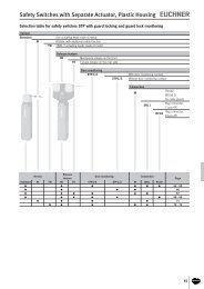
Position Switches - EUCHNER GmbH + Co. KG
Position Switches - EUCHNER GmbH + Co. KG
Position Switches - EUCHNER GmbH + Co. KG

You also want an ePaper? Increase the reach of your titles
YUMPU automatically turns print PDFs into web optimized ePapers that Google loves.
EN<br />
DE<br />
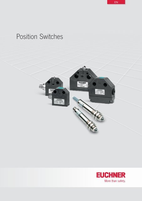
<strong>Position</strong> <strong>Switches</strong>
Internationally successful – the <strong>EUCHNER</strong> company<br />
Headquarters in Leinfelden-Echterdingen<br />
<strong>EUCHNER</strong> <strong>GmbH</strong> + <strong>Co</strong>. <strong>KG</strong> is a world-leading company in the area of industrial safety<br />
technology. <strong>EUCHNER</strong> has been developing and producing high-quality switching systems<br />
for mechanical and systems engineering for more than 60 years.<br />
The medium-sized family-operated company based in Leinfelden, Germany, employs<br />
more than 600 people around the world.<br />
In addition to the production locations in Unterböhringen and Shanghai/China, 15 subsidiaries<br />
and other sales partners in Germany and abroad work for our international<br />
success on the market.<br />
Quality and innovation – the <strong>EUCHNER</strong> products<br />
Logistics center in Leinfelden-Echterdingen<br />
A look into the past shows <strong>EUCHNER</strong> to be a company with a great inventive spirit.<br />
We take the technological and ecological challenges of the future as an incentive for<br />
extraordinary product developments.<br />
<strong>EUCHNER</strong> safety switches monitor safety doors on machines and installations, help to<br />
minimize dangers and risks and thereby reliably protect people and processes. Today,<br />
our products range from electromechanical and electronic components to intelligent<br />
integrated safety solutions. Safety for people, machines and products is one of our<br />
dominant themes.<br />
Production location in Unterböhringen<br />
made<br />
in<br />
Germany<br />
We defi ne future safety technology with the highest quality standards and reliable<br />
technology. Extraordinary solutions ensure the great satisfaction of our customers.<br />
The product ranges are subdivided as follows:<br />
Transponder-coded Safety <strong>Switches</strong> (CES)<br />
Transponder-coded Safety <strong>Switches</strong> with guard locking (CET)<br />
Interlocking and guard locking systems (Multifunctional Gate Box MGB)<br />
Access management systems (Electronic-Key-System EKS)<br />
Electromechanical Safety <strong>Switches</strong><br />
Magnetically coded Safety <strong>Switches</strong> (CMS)<br />
Enabling <strong>Switches</strong><br />
Safety Relays<br />
Emergency Stop Devices<br />
Hand-Held Pendant Stations and Handwheels<br />
Safety <strong>Switches</strong> with AS-Interface<br />
Joystick <strong>Switches</strong><br />
<strong>Position</strong> <strong>Switches</strong><br />
2
<strong>Co</strong>ntents<br />
<strong>Position</strong> switches<br />
General information 4<br />
Precision single hole fixing limit switches 9<br />
with reed contact 10<br />
with snap-action switching element 16<br />
with slow-action switching element 23<br />
Multiple clamping strip for precision single hole fixing limit switches M12 x 1 24<br />
Precision single limit switches 25<br />
Design N01 26<br />
Design NB01 29<br />
Design SN01 29<br />
Design N1A 32<br />
Design N10 36<br />
Design N11 37<br />
Inductive single limit switches 39<br />
Design ENA 40<br />
Design ESN 42<br />
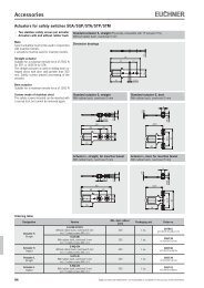
Accessories 46<br />
Round plug connector M12 46<br />
Round plug connector M8 48<br />
LED function display 49<br />
Cable glands 49<br />
Additional products 49<br />
Appendix 50<br />
Terms and explanations 50<br />
Item index 52<br />
094550-10-12/13<br />
3
<strong>Position</strong> <strong>Switches</strong><br />
General information<br />
Precision single hole fixing limit switches with reed contact or<br />
snap-action switching element<br />
<strong>EUCHNER</strong> precision single hole fixing limit switches are technically sophisticated<br />
control switches which have been proving their reliability, day in<br />
and day out, for decades in rough industrial applications.<br />
These mechanically actuated precision single hole fixing limit switches<br />
are IP 67 rated and are entirely maintenance-free.<br />
<strong>EUCHNER</strong> precision single hole fixing limit switches feature a thread on the<br />
upper part and can thus be inserted or screwed through the mounting hole<br />
either from the cable end or from the actuator end. Setting the position<br />
of the operating point opposite the part of the machine to be sensed is<br />
easy with this thread.<br />
The compact overall size and the round design allow installation directly<br />
at the sensing points. This feature dispenses with the complicated levers<br />
or linkages associated with a high level of design complexity and expense.<br />
Precision single limit switches<br />
<strong>EUCHNER</strong> precision single limit switches are technically precise control<br />
switches which have been developed on the basis of practical requirements<br />
in close collaboration with machine tool manufacturers.<br />
The use of high-quality materials, the interplay of sophisticated technology<br />
and practically oriented design guarantee operation under even the<br />
toughest conditions.<br />
<strong>EUCHNER</strong> precision single limit switches are used for positioning and<br />
controlling machines and in industrial installations.<br />
The different designs, with a choice of five different types of plunger, and<br />
easy adjustability from longitudinal to transverse actuation offer the user<br />
a broad range of individual possible applications.<br />
Inductive single limit switches<br />
Inductive single limit switches are used for positioning and control in<br />
all areas of mechanical and systems engineering. Inductive single limit<br />
switches are used for automation tasks in machinery in the wood, textile<br />
and plastics industry.<br />
Due to their non-contact and thus wear-free principle of operation, inductive<br />
single limit switches are insensitive to heavy vibration, heavy soiling<br />
and have an above average mechanical life even in aggressive ambient<br />
conditions.<br />
Interchangeability with mechanical single limit switches means that it is<br />
possible to straightforwardly modify machines. The switches can therefore<br />
be retrofitted on existing machine installations to take full advantage of<br />
the benefits of non-contact switches.<br />
4<br />
Subject to technical modifications; no responsibility is accepted for the accuracy of this information.
<strong>Position</strong> <strong>Switches</strong><br />
Switching elements with reed contact<br />
Reed contact<br />
The reed contact comprises two ferromagnetic contacts in a glass bulb.<br />
When the reed contact is placed in a magnetic field, the contacts adopt<br />
opposite polarities and are closed.<br />
For series EGT with reed contact.<br />
Mechanical switching elements<br />
Changeover contact with snap-action function<br />
Snap-action switching element 1) with single gap and three connections.<br />
For series EGT with snap-action switch and series N01, NB01, SN01 with<br />
soldered connection.<br />
Snap-action switching element 1) with one normally open contact<br />
(NO) and one normally closed contact (NC)<br />
With double gap and electrically isolated switching bridge. The two moving<br />
contacts are electrically isolated from each other. Switching element with<br />
four connections.<br />
For series SN01 with soldered connection and series N1A, N10, N11.<br />
Safety switching element with slow-action switching contact 2)<br />
With one positively driven NC contact and double gap. Switching contact<br />
with two connections.<br />
For use in single limit switches with safety function.<br />
For series NB01 with safety function and series N1A with safety function.<br />
Safety switching element with snap-action switching contact 1)<br />
With one positively driven NC contact and one NO contact. Double gap<br />
and electrically isolated switching bridge. Switching contact with four<br />
connections.<br />
For use in single limit switches with safety function.<br />
For series N1A with safety function.<br />
Solenoid<br />
1) A snap-action contact element has a switching contact that opens and closes independently of the approach speed during actuation.<br />
2) A slow-action contact element has a switching contact that opens and closes depending on the approach speed during actuation.<br />
Subject to technical modifications; no responsibility is accepted for the accuracy of this information.<br />
5
<strong>Position</strong> <strong>Switches</strong><br />
Positively driven contact<br />
Positively driven contacts are used in some switching elements. These<br />
are special switching contacts that are designed to ensure the switching<br />
contacts are always reliably separated. Even if contacts are welded<br />
together, the connection is opened by the actuating force.<br />
It is a common feature of all safety switching elements that at least one<br />
switching contact is designed as a positively driven contact. Often two<br />
positively driven contacts are employed to increase safety using the principle<br />
of duplicated design (redundancy). This dual-channel design ensures<br />
that on the failure of one channel or on a fault in the control circuit (e.g.<br />
in the machine wiring), the interlocking can still be provided with the aid<br />
of the second channel.<br />
Positively driven position switch.<br />
Safety switching elements marked with this symbol are<br />
not available as replacement switching elements.<br />
Inductive switching elements<br />
NO function<br />
The NO function means that the load current flows when the active face<br />
of the inductive switching element is activated and that no current flows<br />
when the active face is not activated.<br />
1<br />
4<br />
3<br />
DC NO contact, PNP<br />
NC function<br />
The NC function means that the load current does not flow when the active<br />
face of the inductive switching element is activated and that current flows<br />
when the active face is not activated.<br />
1<br />
2<br />
3<br />
DC NC, PNP<br />
NO + NC function<br />
The NO + NC function incorporates both an NO function and an NC function.<br />
Associated circuit diagrams and wiring diagrams are given in the technical<br />
data.<br />
1<br />
2<br />
4<br />
3<br />
DC NO + NC contact, PNP<br />
6<br />
Subject to technical modifications; no responsibility is accepted for the accuracy of this information.
<strong>Position</strong> <strong>Switches</strong><br />
Precision single limit switches<br />
Design<br />
Plunger<br />
The die-cast aluminum housings for the <strong>EUCHNER</strong> single limit switches<br />
have been proven in even the harshest conditions with their high strength<br />
and resistance to corrosion.<br />
They do not require a protective paint finish, but can be painted at any<br />
time without prior treatment.<br />
Depending on the design, the hardened plungers made of stainless steel<br />
run precisely in either the anodic oxidized guide bore in the housing or in<br />
a sintered bronze sleeve. These maintenance-free sliding elements make<br />
a key contribution to the reliability and correct operation of the switches.<br />
Even beyond the guaranteed mechanical life.<br />
LED indicator<br />
Cable entry<br />
Switching<br />
element<br />
Exterior diaphragm<br />
To provide protection against resinous cooling lubricants and against the<br />
penetration of very small particles, e.g. saw dust, graphite and glass dust,<br />
and to provide protection against freezing in the low temperature range,<br />
a series with an exterior diaphragm is available.<br />
The exterior diaphragm provides additional sealing of the plunger outside<br />
the housing.<br />
The plunger guides in the housing are thus reliably protected from the<br />
penetration of the cooling lubricant. Plunger sticking is prevented and the<br />
replacement of the switch or plunger is unnecessary. Technical data for<br />
this series see page 35.<br />
Seals<br />
<strong>EUCHNER</strong> uses the high-quality and proven acrylonitrile-butadiene rubber<br />
(NBR) for all seals and sealed areas. This material is resistant to oils,<br />
greases, fuels, hydraulic fluids and most known cooling lubricants. Moreover,<br />
NBR possesses high mechanical strength over a wide temperature<br />
range and so it is perfectly suitable for the highly stressed diaphragm seal,<br />
which separates the plunger compartment and the interior of the switch.<br />
The material of the diaphragm seal is a key criterion for the quality,<br />
mechanical life and precision of the <strong>EUCHNER</strong> precision multiple limit<br />
switches. The same material is used for the cover seal and the cable entry.<br />
Seals made of Viton or silicone are available on request for special<br />
applications.<br />
Seals made<br />
of NBR<br />
Subject to technical modifications; no responsibility is accepted for the accuracy of this information.<br />
7
<strong>Position</strong> <strong>Switches</strong><br />
Adjustability<br />
On the chisel plungers and the roller plungers (normal and extended) the<br />
approach direction can be changed by 90° at any time. After unscrewing<br />
the locking pin, the plunger can be rotated by 90°.<br />
LED function display<br />
If required, the <strong>EUCHNER</strong> single limit switches of design N1A can be<br />
equipped with an LED function display (AC/DC 10 - 60 V or AC 110/230 V,<br />
color red).<br />
Built-in electronic regulation ensures that the luminosity remains constant<br />
independent of the voltage applied.<br />
<strong>EUCHNER</strong><br />
X1 X2<br />
LE060 rt 12-60V<br />
Cable connection<br />
<strong>EUCHNER</strong> position switches are tested to degree of protection IP 67 in<br />
accordance with IEC 60529. In order to obtain this degree of protection,<br />
only high-quality metal cable glands with a captive sealing ring are used.<br />
A selection for different cable diameters is listed on page 49.<br />
8<br />
Subject to technical modifications; no responsibility is accepted for the accuracy of this information.
<strong>Position</strong> <strong>Switches</strong><br />
Single hole fixing limit switches – cylindrical design<br />
The round design with simple, single-hole assembly allows installation of<br />
the controls directly at the scanning points. Exact adjustment is permitted<br />
by means of the precision metric thread. The limit switches with inert gas<br />
contact (reed contact) can be operated up to a water column pressure of<br />
30 meters with degree of protection IP 68.<br />
Features<br />
ff<br />
6 basic types M12 x 1 to M18 x 1.5<br />
ff<br />
Housing of nickel-plated brass or stainless steel<br />
ff<br />
Mechanical life up to 30 million operating cycles<br />
ff<br />
Degree of protection IP 68 / IP 67<br />
ff<br />
Operating point accuracy ± 0.01 mm max.<br />
ff<br />
With hard-wired cable or with M12 plug connection<br />
ff<br />
Temperature range -30 °C to +120 °C<br />
Subject to technical modifications; no responsibility is accepted for the accuracy of this information.<br />
9
<strong>Position</strong> <strong>Switches</strong><br />
Precision single hole fixing<br />
limit switches<br />
Ambient temperature up to 120 °C<br />
Design EGT12, M12 x 1, dome plunger<br />
<strong>Co</strong>nnection cable, double insulated<br />
Design EGT12, M12 x 1, dome plunger<br />
<strong>Co</strong>nnection cable, double insulated<br />
ff<br />
With reed contact and protective diode<br />
ff<br />
Plunger material stainless steel<br />
ff<br />
Any installation position<br />
Dimension drawings<br />
M12x1<br />
R2,5<br />
∅ 6<br />
R2,5<br />
M12x1<br />
∅ 6<br />
54<br />
34<br />
4<br />
4<br />
4<br />
0,8 -0,6<br />
2,5 ±0,3<br />
End position<br />
0,5<br />
Differential travel<br />
34<br />
End position<br />
0,5<br />
Differential travel<br />
Operating point<br />
4<br />
0,8 -0,6<br />
2,5 ±0,3<br />
Operating point<br />
SW17<br />
61<br />
SW17<br />
∅ 5,8<br />
∅ 12,6<br />
∅ 5,4<br />
∅ 12,6<br />
Never switch incandescent lamps. Not even<br />
for test purposes.<br />
Single hole fixing limit switches must not be<br />
used as an end stop.<br />
Wiring diagrams<br />
BN<br />
WH<br />
BN<br />
BU<br />
BN<br />
WH<br />
BN<br />
BU<br />
Technical data<br />
Housing material<br />
Sleeve Stainless steel Plastic<br />
Threaded section Stainless steel Stainless steel<br />
Degree of protection acc. to IEC 60529 IP 65 IP 68<br />
Ambient temperature [°C] -25 1) … +120 -25 1) … +80<br />
Approach speed, max. [m/min] 8 8<br />
Mechanical life<br />
axial actuation 30 x 10 6 operating cycles (1 x 10 6 at 120 °C) 30 x 10 6 operating cycles<br />
radial actuation - 1 x 10 6 operating cycles (dog 30°)<br />
Operating point accuracy 2) [mm] ± 0.01 ± 0.01<br />
Actuating force (end position) [N] approx. 16 approx. 16<br />
Switching element Reed contact Reed contact<br />
Switching contact 1 NO or 1 NC 1 NO or 1 NC<br />
<strong>Co</strong>ntact material Rhodium Rhodium<br />
Rated insulation voltage U i [V] 50 50 <br />
Utilization category according to IEC 60947-5-1<br />
AC-12 U e 30 V I e 0.3 A<br />
DC-13 U e 24 V I e 0.3 A<br />
AC-12 U e 30 V I e 0.3 A<br />
DC-13 U e 24 V I e 0.3 A<br />
Switching current, min., at 24 V [mA] 1 1<br />
Switching voltage, min. [V DC] 1 1<br />
Short circuit protection<br />
(control circuit fuse)<br />
[A gG] 0.4 0.4<br />
<strong>Co</strong>nnection Silicone cable 2 x 0.5 mm² PUR cable 2 x 0.5 mm²<br />
1) Cable hard wired.<br />
2) The reproducible operating point accuracy relates to axial actuation, after run-in of approx. 2,000 operating cycles.<br />
3) Mating connector see page 46 and 47.<br />
Ordering table<br />
1 NO<br />
<strong>Co</strong>nnection cable 3 m<br />
104223<br />
EGT12A3000C2250<br />
<strong>Co</strong>nnection cable 5 m -<br />
-<br />
082201<br />
EGT12A5000<br />
Plug connector - -<br />
<strong>Co</strong>nnection cable 3 m On request -<br />
1 NC<br />
<strong>Co</strong>nnection cable 5 m -<br />
078848<br />
EGT12R5000<br />
Plug connector - -<br />
10<br />
Subject to technical modifications; no responsibility is accepted for the accuracy of this information.
<strong>Position</strong> <strong>Switches</strong><br />
Design EGT12, M12 x 1, dome plunger<br />
Plug connector M12 with PE connection<br />
Design EGT12, M12 x 1, dome plunger<br />
Plug connector M12, long plunger<br />
Dimension drawings<br />
R2,5<br />
M12x1<br />
∅ 6<br />
0,8 -0,6<br />
2,5 ±0,3<br />
R 2,5<br />
12x1<br />
∅ 6<br />
0,8 -0,6<br />
6,5±0,3<br />
75 4<br />
34<br />
4<br />
SW17<br />
0,5<br />
End position<br />
Differential travel<br />
8<br />
4,5<br />
75<br />
Operating point<br />
34<br />
4<br />
SW 17<br />
End position<br />
Differential travel<br />
Operating point<br />
∅ 10,5<br />
∅ 10,5<br />
M12x1<br />
12x1<br />
Wiring diagrams<br />
5<br />
4 3<br />
1<br />
4<br />
5<br />
<br />
5<br />
4 3<br />
1<br />
4<br />
5<br />
<br />
1 2<br />
1<br />
4<br />
5<br />
<br />
1 2<br />
1<br />
4<br />
5<br />
<br />
Brass, nickel-plated<br />
Stainless steel<br />
IP 67<br />
Mating connector inserted and screwed tight<br />
Brass, nickel-plated<br />
Stainless steel<br />
IP 67<br />
Mating connector inserted and screwed tight<br />
-25 … +80 -25 … +80<br />
8 5<br />
30 x 10 6 operating cycles<br />
5 x 10 6 operating cycles<br />
1 x 10 6 operating cycles (dog 30°)<br />
± 0.01 ± 0.01<br />
approx. 16 approx. 16<br />
Reed contact<br />
Reed contact<br />
1 NO or 1 NC 1 NO or 1 NC<br />
Rhodium<br />
Rhodium<br />
50 50<br />
AC-12 U e 30 V I e 0.3 A<br />
DC-13 U e 24 V I e 0.3 A<br />
AC-12 U e 30 V I e 0.3 ADC-13 U e 24 V I e 0.3 A<br />
1 1<br />
1 1<br />
0.4 0.4<br />
Plug connector M12 3) Plug connector M12 3)<br />
- -<br />
- -<br />
075426<br />
EGT12ASFM5<br />
095112<br />
EGT12ASFM5C2083<br />
- -<br />
- -<br />
075427<br />
EGT12RSFM5<br />
On request<br />
Subject to technical modifications; no responsibility is accepted for the accuracy of this information.<br />
11
<strong>Position</strong> <strong>Switches</strong><br />
Precision single hole fixing<br />
limit switches<br />
Design EGT11, M14 x 1, ball plunger<br />
<strong>Co</strong>nnection cable 0.5 m with plug connector M8<br />
Design EGT11, M14 x 1, ball plunger<br />
Plug connector M12 with PE connection<br />
ff<br />
With reed contact and protective diode<br />
ff<br />
Plunger material stainless steel<br />
ff<br />
Any installation position<br />
Dimension drawings<br />
R2<br />
∅ 15,8<br />
M14x1<br />
∅ 6<br />
0,8 -0,6<br />
2,5 ±0,3<br />
R2<br />
∅ 15,8<br />
M14x1<br />
∅ 6<br />
0,8 -0,6<br />
2,5 ±0,3<br />
61<br />
4<br />
34<br />
3<br />
SW10<br />
4<br />
SW15<br />
0,5<br />
End position<br />
Differential travel<br />
Operating point<br />
75 4<br />
34<br />
4 3<br />
SW10<br />
SW15<br />
0,5<br />
End position<br />
Differential travel<br />
Operating point<br />
50 +10<br />
M8<br />
M12x1<br />
Never switch incandescent lamps. Not even<br />
for test purposes.<br />
Single hole fixing limit switches must not be<br />
used as an end stop.<br />
Technical data<br />
Housing material<br />
Degree of protection acc. to IEC 60529<br />
Wiring diagrams<br />
2 4<br />
1 3<br />
2<br />
4<br />
5<br />
4 3<br />
1 2<br />
Sleeve Brass, nickel-plated Brass, nickel-plated<br />
Threaded section Stainless steel Stainless steel<br />
IP 67<br />
Mating connector inserted and screwed tight<br />
1<br />
4<br />
5<br />
1<br />
4<br />
5<br />
<br />
<br />
IP 67<br />
Mating connector inserted and screwed tight<br />
Ambient temperature [°C] -5 … +65 -25 … +80<br />
Approach speed, max. [m/min] 60 60<br />
Mechanical life<br />
axial actuation 30 x 10 6 operating cycles 30 x 10 6 operating cycles<br />
radial actuation - 5 x 10 6 operating cycles (dog 15°)<br />
Operating point accuracy 2) [mm] ± 0.01 ± 0.01<br />
Actuating force (end position) [N] approx. 2 approx. 3<br />
Switching element Reed contact Reed contact<br />
Switching contact 1 NC 1 NO or 1 NC<br />
<strong>Co</strong>ntact material Rhodium Rhodium<br />
Rated insulation voltage U i [V] 50 50<br />
Utilization category according to IEC 60947-5-1<br />
AC-12 U e 30 V I e 0.3 A<br />
DC-13 U e 24 V I e 0.3 A<br />
AC-12 U e 30 V I e 0.3 A<br />
DC-13 U e 24 V I e 0.3 A<br />
Switching current, min., at 24 V [mA] 1 1<br />
Switching voltage, min. [V DC] 1 1<br />
Short circuit protection<br />
(control circuit fuse)<br />
[A gG] 0.4 0.4<br />
<strong>Co</strong>nnection Plug connector M8 3) Plug connector M12 3)<br />
1) Cable hard wired.<br />
2) The reproducible operating point accuracy relates to axial actuation, after run-in of approx. 2,000 operating cycles.<br />
3) Mating connector M8 see page 48. Mating connector M12 see page 46 and 47<br />
Ordering table<br />
1 NO<br />
1 NC<br />
<strong>Co</strong>nnection cable 0.5 m<br />
with plug connector M8<br />
- -<br />
<strong>Co</strong>nnection cable 5 m - -<br />
Plug connector -<br />
<strong>Co</strong>nnection cable 0.5 m<br />
with plug connector M8<br />
084000<br />
EGT11R2N50SAM4<br />
093352<br />
EGT11A2NSFM5<br />
<strong>Co</strong>nnection cable 5 m - -<br />
Plug connector -<br />
-<br />
091848<br />
EGT11R2NSFM5<br />
12<br />
Subject to technical modifications; no responsibility is accepted for the accuracy of this information.
<strong>Position</strong> <strong>Switches</strong><br />
Design EGT12, M12 x 1, roller plunger<br />
Plug connector M12, double insulated<br />
Dimension drawings<br />
R2,5<br />
M12x1<br />
SW10<br />
0,8 -0,6<br />
4<br />
0,5<br />
2,5 ±0,3<br />
SW17<br />
77<br />
36<br />
3<br />
End position<br />
Differential travel<br />
Operating point<br />
4<br />
∅ 10,5<br />
M12x1<br />
Wiring diagrams<br />
4 3<br />
1<br />
2<br />
4<br />
1 2<br />
1<br />
2<br />
Brass, nickel-plated<br />
Stainless steel<br />
IP 67<br />
Mating connector inserted and screwed tight<br />
-25 … +80<br />
20<br />
30 x 10 6 operating cycles<br />
± 0.01<br />
approx. 16<br />
Reed contact<br />
1 NO or 1 NC<br />
Rhodium<br />
50 <br />
AC-12 U e 30 V I e 0.3 A<br />
DC-13 U e 24 V I e 0.3 A<br />
1<br />
1<br />
0.4<br />
Plug connector M12 3)<br />
-<br />
-<br />
078483<br />
EGT12ARSEM4C1888<br />
-<br />
-<br />
079139<br />
EGT12RRSEM4C1888<br />
Subject to technical modifications; no responsibility is accepted for the accuracy of this information.<br />
13
<strong>Position</strong> <strong>Switches</strong><br />
Precision single hole fixing<br />
limit switches<br />
Design EGT1/4, M14 x 1, ball plunger<br />
<strong>Co</strong>nnection cable, double insulated/ connector M12<br />
5)<br />
For mating connector<br />
with LED display<br />
Design EGT1/4, M14 x 1, ball plunger<br />
Plug connector M12<br />
ff<br />
With reed contact<br />
ff<br />
Plunger material stainless steel<br />
ff<br />
Any installation position<br />
Dimension drawings<br />
∅ 15,8<br />
R2<br />
M14x1<br />
∅ 6<br />
0,8 -0,6<br />
R2<br />
∅ 15,8<br />
M14x1<br />
∅ 6<br />
4<br />
0,8 -0,6<br />
2,5 ±0,3<br />
34<br />
4 3<br />
SW10<br />
0,5<br />
SW15<br />
63<br />
4<br />
2,5 ±0,3<br />
3<br />
SW10<br />
34<br />
4<br />
0,5<br />
End position<br />
Differential travel<br />
Operating point<br />
End position<br />
Differential travel<br />
Operating point<br />
50<br />
SW15<br />
63<br />
∅ 12,6<br />
∅ 5,4<br />
M12x1<br />
M12x1<br />
Never switch incandescent lamps. Not even<br />
for test purposes.<br />
Single hole fixing limit switches must not be<br />
used as an end stop.<br />
Wiring diagrams<br />
BN<br />
BU<br />
4 3<br />
3<br />
4<br />
4 3<br />
BN<br />
BU<br />
1 2<br />
1<br />
2<br />
1 2<br />
1<br />
4<br />
Technical data<br />
Housing material<br />
Sleeve Plastic Brass, nickel-plated Brass, nickel-plated<br />
Threaded section Stainless steel Stainless steel<br />
IP 67<br />
Degree of protection acc. to IEC 60529 IP 68 IP 67 4) Mating connector inserted and screwed tight<br />
Ambient temperature [°C] -25 1) … +80 -25 … +80 -25 … +80<br />
Approach speed, max. [m/min] 8 8<br />
Mechanical life (axial) 30 x 10 6 operating cycles 30 x 10 6 operating cycles<br />
Operating point accuracy 2) [mm] ± 0.01 ± 0.01<br />
Actuating force (end position) [N] Approx. 16 / 3 on request Approx. 16 / 3 on request<br />
Switching element Reed contact Reed contact<br />
Switching contact 1 NO or 1 NC 1 NO or 1 NC<br />
<strong>Co</strong>ntact material Rhodium Rhodium<br />
Rated insulation voltage U i [V] 250 50 50<br />
Utilization category<br />
according to IEC 60947-5-1<br />
AC-12<br />
U e 230 V I e 0.03 A<br />
U e 24 V I e 0.3 A<br />
U e 30 V I e 0.3 A<br />
U e 24 V I e 0.3 A<br />
AC-12 U e 30 V I e 0.3 A<br />
DC-13 U e 24 V I e 0.3 A<br />
DC-13<br />
Switching current, min., at 24 V [mA] 1 1<br />
Switching voltage, min. [V DC] 1 1<br />
Short circuit protection<br />
(control circuit fuse)<br />
[A gG] 0.4 0.4<br />
<strong>Co</strong>nnection<br />
PUR cable<br />
2 x 0.5 mm², Plug connector M12 3) Plug connector M12 3)<br />
encapsulated<br />
1) Cable hard wired.<br />
2) The reproducible operating point accuracy relates to axial actuation, after run-in of approx. 2,000 operating cycles.<br />
3) Mating connector see page 46 and 47.<br />
Ordering table<br />
1 NO<br />
1 NC<br />
<strong>Co</strong>nnection cable 2 m<br />
<strong>Co</strong>nnection cable 5 m<br />
Plug connector<br />
<strong>Co</strong>nnection cable 2 m<br />
<strong>Co</strong>nnection cable 5 m<br />
Plug connector<br />
001366 5)<br />
EGT1/4A2000<br />
001368 5)<br />
EGT1/4A5000<br />
033976<br />
EGT1/4ASEM4<br />
001371 5)<br />
EGT1/4R2000<br />
001372 5)<br />
EGT1/4R5000<br />
033982<br />
EGT1/4RSEM4<br />
-<br />
-<br />
075644<br />
EGT1/4ASEM4C1802<br />
-<br />
-<br />
-<br />
14<br />
Subject to technical modifications; no responsibility is accepted for the accuracy of this information.
<strong>Position</strong> <strong>Switches</strong><br />
Made of high-quality<br />
stainless steel<br />
Design EGT1/4, M14 x 1, ball plunger<br />
<strong>Co</strong>nnection cable, max. pressure 300 kPa<br />
With scraper made of PU<br />
Design EGT1/4, M14 x 1, ball plunger<br />
Plug connector M12<br />
With scraper made of PU<br />
Design EGT1/4, M14 x 1, dome plunger<br />
Plug connector M12<br />
Dimension drawings<br />
∅ 15,8<br />
M14x1<br />
∅ 6<br />
-0,6<br />
0,8<br />
0,5<br />
±0,3<br />
2,5<br />
Scraper<br />
Material PU<br />
91 Shore A<br />
<strong>Co</strong>lor gray<br />
∅ 15,8<br />
M14x1<br />
∅ 6<br />
0,8-0,6<br />
7,5±0,3<br />
Scraper<br />
Material PU<br />
91 Shore A<br />
<strong>Co</strong>lor gray<br />
∅ 15,8<br />
M14x1<br />
∅ 6<br />
EGT..A... 4,5<br />
EGT..R... 9,0<br />
0,8 -0,6<br />
11,3±0,3<br />
50<br />
34<br />
3<br />
4<br />
4<br />
9<br />
SW10<br />
SW15<br />
Differential travel<br />
End position<br />
Operating point<br />
34<br />
4<br />
SW 15<br />
63<br />
5<br />
End position<br />
Differential travel<br />
Operating point<br />
47<br />
4<br />
12,5<br />
SW 15<br />
76<br />
End position<br />
(dimension type<br />
dependent)<br />
Differential travel<br />
Operating point<br />
∅ 6,5<br />
∅ 12,6<br />
M12x1<br />
M12x1<br />
Wiring diagrams<br />
BN<br />
BU<br />
4 3<br />
1 2<br />
3<br />
4<br />
1<br />
2<br />
4 3<br />
1 2<br />
3<br />
4<br />
1<br />
2<br />
High-quality stainless steel<br />
IP 68<br />
Brass, nickel-plated<br />
Stainless steel<br />
IP 67<br />
Mating connector inserted and screwed tight<br />
Brass, nickel-plated<br />
Stainless steel<br />
IP 67<br />
Mating connector inserted and screwed tight<br />
-25 … +80 -25 … +80 -25 … +80<br />
8 approx. 16 8<br />
30 x 10 6 operating cycles 5 x 10 6 operating cycles 30 x 10 6 operating cycles<br />
± 0.01 ± 0.01 ± 0.01<br />
approx. 16 approx. 16 approx. 16<br />
Reed contact Reed contact Reed contact<br />
1 NO 1 NO or 1 NC 1 NO<br />
Rhodium Rhodium Rhodium<br />
50 50 50<br />
AC-12 U e 30 V I e 0.3 A<br />
DC-13 U e 24 V I e 0.3 A<br />
AC-12 U e 30 V I e 0.3 A<br />
DC-13 U e 24 V I e 0.3 A<br />
AC-12 U e 30 V I e 0.3 A<br />
DC-13 U e 24 V I e 0.3 A<br />
1 1 1<br />
1 1 1<br />
0.4 0.4 0.4<br />
Hydrofirm cable 2 x 0.5 mm², encapsulated Plug connector M12 3) Plug connector M12 3)<br />
094982<br />
EGT1/4A2000C2079<br />
-<br />
102476<br />
EGT1/4A2000C2137<br />
- - -<br />
-<br />
095278<br />
EGT1/4ASEM4C2088<br />
098071<br />
EGT1/4ASEM4C2137<br />
- - -<br />
- - -<br />
-<br />
104316<br />
EGT1/4RSEM4C2088<br />
104372<br />
EGT1/4RSEM4C2137<br />
Subject to technical modifications; no responsibility is accepted for the accuracy of this information.<br />
15
<strong>Position</strong> <strong>Switches</strong><br />
Precision single hole fixing<br />
limit switches<br />
Design EGM12, M12 x 1, flat plunger<br />
<strong>Co</strong>nnection cable, double insulated<br />
Design EGM12, M12 x 1, flat plunger<br />
Plug connector M12<br />
ff<br />
With snap-action switching element<br />
ff<br />
Plunger material stainless steel<br />
ff<br />
Any installation position<br />
Dimension drawings<br />
1,5 +0,2<br />
M12x1<br />
∅ 5,5<br />
0,5<br />
0,12 ±0,06<br />
1 ±0,3<br />
1,5 +0,2<br />
M12x1<br />
0,5<br />
0,12 ±0,06<br />
1 ±0,3<br />
1200 40<br />
16<br />
8<br />
∅ 6<br />
30<br />
End position<br />
Differential travel<br />
Operating point<br />
16<br />
4<br />
57<br />
14<br />
SW17 ∅ 10,5<br />
End position<br />
Differential travel<br />
Operating point<br />
∅ 14<br />
Single hole fixing limit switches must not be<br />
used as an end stop.<br />
Wiring diagrams<br />
BN<br />
BU<br />
BK<br />
… C1791<br />
BN<br />
GN<br />
WH<br />
… C1820<br />
4 3<br />
1 2<br />
1<br />
2<br />
4<br />
Technical data<br />
Housing material Stainless steel Stainless steel<br />
Degree of protection acc. to IEC 60529 IP 65<br />
IP 65<br />
Mating connector inserted and screwed tight<br />
Ambient temperature [°C] -20 1) … +80 -30 … +80 -20 … +80 -30 … +85<br />
Approach speed, max. [m/min] 8 8<br />
Mechanical life (axial) 1 x 10 6 operating cycles 1 x 10 6 operating cycles<br />
Operating point accuracy 2) [mm] ± 0.01 ± 0.01<br />
Actuating force (end position) [N] approx. 16 approx. 16<br />
Switching element Snap-action switching contact Snap-action switching contact<br />
Switching contact 1 changeover contact 1 changeover contact<br />
<strong>Co</strong>ntact material Silver alloy, gold-plated Silver alloy, gold-plated<br />
Rated insulation voltage U i [V] 250 50<br />
Rated impulse withstand voltage U imp 2.5 1.5<br />
Utilization category according to IEC 60947-5-1<br />
AC-15 U e 230 V I e 0.5 A<br />
DC-13 U e 24 V I e 0.6 A<br />
AC-15 U e 50 V I e 0.5 A<br />
DC-13 U e 24 V I e 0.6 A<br />
Switching current, min., at 24 V [mA] 10 10<br />
Switching voltage, min. [V DC] 12 12<br />
Short circuit protection<br />
(control circuit fuse)<br />
[A gG] 2 2<br />
<strong>Co</strong>nnection<br />
PUR cable<br />
3 x 0.5 mm²<br />
Silicone cable<br />
3 x 0.5 mm²<br />
1) Cable hard wired.<br />
2) The reproducible operating point accuracy relates to axial actuation, after run-in of approx. 2,000 operating cycles.<br />
3) Mating connector see page 46, 47 and 48.<br />
Plug connector M12 3)<br />
Ordering table<br />
1 changeover contact<br />
<strong>Co</strong>nnection cable 1.2 m<br />
075556<br />
EGM12-1200C1791<br />
076464<br />
EGM12-1200C1820<br />
<strong>Co</strong>nnection cable 2 m - - -<br />
<strong>Co</strong>nnection cable 4 m<br />
076154<br />
EGM12-4000C1791<br />
- -<br />
<strong>Co</strong>nnection cable 5 m - - -<br />
Plug connector - -<br />
082205<br />
EGM12SEM4<br />
-<br />
093733<br />
EGM12SEM4C1820<br />
16<br />
Subject to technical modifications; no responsibility is accepted for the accuracy of this information.
<strong>Position</strong> <strong>Switches</strong><br />
Design EGM12, M12 x 1, flat plunger<br />
Plug connector M8<br />
Design EGT1, M12 x 1, ball plunger<br />
<strong>Co</strong>nnection cable with PE connection<br />
Design EGT1, M12 x 1, ball plunger<br />
Plug connector M12<br />
Dimension drawings<br />
M12x1<br />
M12x1<br />
1,5 +0,2<br />
M12x1<br />
∅ 5,5<br />
>0,2<br />
±0,06<br />
0,12<br />
1 ±0,3<br />
4<br />
∅ 6<br />
4<br />
∅ 6<br />
50<br />
10,8<br />
4,8<br />
SW17<br />
8 4<br />
3<br />
4 16<br />
End position<br />
Differential travel<br />
∅ 15,8<br />
Operating point<br />
65<br />
27<br />
18<br />
3<br />
SW17<br />
∅ 12,6<br />
0,5<br />
End position<br />
0,15<br />
Differential travel<br />
±0,3<br />
3<br />
3,5<br />
Operating point<br />
74<br />
27<br />
18<br />
3<br />
SW17<br />
∅ 12,6<br />
0,5<br />
End position<br />
0,15<br />
Differential travel<br />
±0,3<br />
3,5<br />
Operating point<br />
M8x1<br />
M12x1<br />
SW10<br />
∅ 6,0<br />
M12x1<br />
Wiring diagrams<br />
1<br />
4<br />
3<br />
1<br />
4<br />
BN<br />
BU<br />
BK<br />
GNYE<br />
<br />
4 3<br />
1<br />
2<br />
4<br />
1 2<br />
Stainless steel Brass, nickel-plated Brass, nickel-plated<br />
IP 65<br />
Mating connector inserted and screwed tight<br />
IP 67<br />
IP 67<br />
Mating connector inserted and screwed tight<br />
-20 … +85 -25 1) … +80 -25 … +80<br />
8 8 8<br />
1 x 10 6 operating cycles 1 x 10 6 operating cycles 1 x 10 6 operating cycles<br />
± 0.01 ± 0.01 ± 0.01<br />
approx. 16 approx. 20 approx. 20<br />
Snap-action switching contact Snap-action switching contact Snap-action switching contact<br />
1 NO 1 changeover contact 1 changeover contact<br />
Silver alloy, gold-plated Silver alloy, gold-plated Silver alloy, gold-plated<br />
50 250 50<br />
1.5 2.5 2.5<br />
AC-15 U e 24 V I e 0.5 A<br />
DC-13 U e 24 V I e 0.6 A<br />
AC-15 U e 230 V I e 0.5A<br />
DC-13 U e 24 V I e 0.6 A<br />
AC-15 U e 50 V I e 0.5 A<br />
DC-13 U e 24 V I e 0.6 A<br />
10 10 10<br />
12 12 12<br />
2 2 2<br />
Plug connector M8 3) PUR cable 4 x 0.5 mm² Plug connector M12 3)<br />
- - -<br />
-<br />
092695<br />
EGT1M12-2000<br />
-<br />
- - -<br />
-<br />
077228<br />
EGM12SAM3C1868<br />
093364<br />
EGT1M12-5000<br />
-<br />
-<br />
093365<br />
EGT1M12SEM4<br />
Subject to technical modifications; no responsibility is accepted for the accuracy of this information.<br />
17
<strong>Position</strong> <strong>Switches</strong><br />
Precision single hole fixing<br />
limit switches<br />
ff<br />
With snap-action switching element<br />
ff<br />
Plunger material stainless steel<br />
ff<br />
Any installation position<br />
Design EGT1, M14 x 1, ball plunger<br />
<strong>Co</strong>nnection cable with PE connection<br />
Dimension drawings<br />
∅ 15,8<br />
M14x1<br />
∅ 6<br />
Design EGT1, M14 x 1, ball plunger<br />
Plug connector M12<br />
∅ 15,8<br />
M14x1<br />
∅ 6<br />
74<br />
3<br />
65<br />
27<br />
4<br />
4<br />
3<br />
SW 15<br />
0,5<br />
End position<br />
0,15<br />
Differential travel<br />
±0,3<br />
3,5<br />
Operating point<br />
27<br />
SW 15<br />
4<br />
0,5<br />
End position<br />
0,15<br />
Differential travel<br />
±0,3<br />
3,5<br />
Operating point<br />
4<br />
SW 10<br />
∅ 6,0<br />
∅ 12<br />
M12x1<br />
Single hole fixing limit switches must not be<br />
used as an end stop.<br />
Wiring diagrams<br />
BN<br />
4 3<br />
BU<br />
1<br />
BK<br />
3<br />
GNYE 4<br />
1 2<br />
Technical data<br />
Housing material Brass, nickel-plated Brass, nickel-plated<br />
Degree of protection acc. to IEC 60529 IP 67<br />
IP 67<br />
Mating connector inserted and screwed tight<br />
Ambient temperature [°C] -25 1) … +80 -25 … +80<br />
Approach speed, max. [m/min] 8 8<br />
Mechanical life (axial) 1 x 10 6 operating cycles 1 x 10 6 operating cycles<br />
Operating point accuracy 2) [mm] ± 0.01 ± 0.01<br />
Actuating force (end position) [N] approx. 20 approx. 20<br />
Switching element Snap-action switching contact Snap-action switching contact<br />
Switching contact 1 changeover contact 1 changeover contact<br />
<strong>Co</strong>ntact material Silver alloy, gold-plated Silver alloy, gold-plated<br />
Rated insulation voltage U i [V] 250 50<br />
Rated impulse withstand voltage U imp 2.5 2.5<br />
Utilization category according to IEC 60947-5-1<br />
AC-15 U e 230 V I e 0.5 A<br />
DC-13 U e 24 V I e 0.6 A<br />
AC-15 U e 50 V I e 0.5 A<br />
DC-13 U e 24 V I e 0.6 A<br />
Switching current, min., at 24 V [mA] 10 10<br />
Switching voltage, min. [V DC] 12 12<br />
Short circuit protection<br />
(control circuit fuse)<br />
[A gG] 2 2<br />
<strong>Co</strong>nnection PUR cable 4 x 0.5 mm² Plug connector M12 3)<br />
1) Cable hard wired.<br />
2) The reproducible operating point accuracy relates to axial actuation, after run-in of approx. 2,000 operating cycles.<br />
3) Mating connector see page 46 and 47.<br />
Ordering table<br />
1 changeover contact<br />
<strong>Co</strong>nnection cable 2 m<br />
<strong>Co</strong>nnection cable 5 m<br />
001732<br />
EGT1-2000<br />
001733<br />
EGT1-5000<br />
Plug connector -<br />
-<br />
-<br />
019727<br />
EGT1SEM4<br />
18<br />
Subject to technical modifications; no responsibility is accepted for the accuracy of this information.
<strong>Position</strong> <strong>Switches</strong><br />
For plug connector<br />
with LED display<br />
Design EGT1, M14 x 1, ball plunger<br />
Plug connector M12<br />
Suitable for aggressive coolants,<br />
diaphragm made out of Viton<br />
Design EGT1, M14 x 1, ball plunger<br />
Plug connector M12<br />
Dimension drawings<br />
∅ 15,8<br />
M14x1<br />
∅ 6<br />
∅ 15,8<br />
M14x1<br />
∅ 6<br />
27<br />
0,5<br />
0,15<br />
3,5<br />
4<br />
74<br />
3<br />
SW 15<br />
±0,3<br />
4<br />
27<br />
End position<br />
Differential travel<br />
Operating point<br />
0,5<br />
0,15<br />
74<br />
3<br />
SW 15<br />
±0,3<br />
3,5<br />
4<br />
4<br />
End position<br />
Differential travel<br />
Operating point<br />
M12x1<br />
M12x1<br />
Wiring diagrams<br />
+<br />
BN<br />
1<br />
4 3<br />
1<br />
WH<br />
2<br />
2<br />
BK 4<br />
GN YE YE<br />
4<br />
BU<br />
-<br />
3<br />
1 2<br />
3<br />
4 3<br />
1 2<br />
1<br />
3<br />
4<br />
Brass, nickel-plated<br />
IP 67<br />
Mating connector inserted and screwed tight<br />
Brass, nickel-plated<br />
IP 67<br />
Mating connector inserted and screwed tight<br />
-25 … +80 -5 … +80<br />
8 8<br />
1 x 10 6 operating cycles 1 x 10 6 operating cycles<br />
± 0.01 ± 0.01<br />
approx. 20 approx. 20<br />
Snap-action switching contact<br />
Snap-action switching contact<br />
1 changeover contact 1 changeover contact<br />
Silver alloy, gold-plated<br />
Silver alloy, gold-plated<br />
50 50<br />
2.5 2.5<br />
DC-13 U e 24 V I e 0.6 A<br />
AC-15 U e 50 V I e 0.5 ADC-13 U e 24 V I e 0.6 A<br />
10 10<br />
12 12<br />
2 2<br />
Plug connector M12 3) Plug connector M12 3)<br />
- -<br />
- -<br />
054250<br />
EGT1SEM4C1613<br />
077347<br />
EGT1SEM4C1832<br />
Subject to technical modifications; no responsibility is accepted for the accuracy of this information.<br />
19
<strong>Position</strong> <strong>Switches</strong><br />
Precision single hole fixing<br />
limit switches<br />
ff<br />
With snap-action switching element<br />
ff<br />
Plunger material stainless steel<br />
ff<br />
Any installation position<br />
Design EGT2, M18 x 1.5, ball plunger<br />
<strong>Co</strong>nnection cable with PE connection<br />
Dimension drawings<br />
∅ 24<br />
M18x1,5<br />
∅ 9<br />
Design EGT2, M18 x 1.5, ball plunger<br />
Plug connector M12<br />
∅ 24<br />
M18x1,5<br />
∅ 9<br />
5<br />
32<br />
32<br />
SW 22<br />
93<br />
85<br />
4<br />
5<br />
4<br />
SW 22<br />
4<br />
0,5<br />
0,5<br />
4<br />
End position<br />
Differential travel<br />
Operating point<br />
4<br />
0,5<br />
0,5<br />
4<br />
End position<br />
Differential travel<br />
Operating point<br />
∅ 16<br />
∅ 16<br />
SW 14<br />
∅ 7,2<br />
M12x1<br />
Single hole fixing limit switches must not be<br />
used as an end stop.<br />
Wiring diagrams<br />
BN<br />
BU<br />
BK<br />
BK<br />
GNYE<br />
<br />
2 4<br />
1 3<br />
1<br />
2<br />
3<br />
4<br />
Technical data<br />
Housing material Brass, nickel-plated Brass chromium plated<br />
Degree of protection acc. to IEC 60529 IP 67<br />
IP 67<br />
Mating connector inserted and screwed tight<br />
Ambient temperature [°C] -5 … +60 -5 … +60<br />
Approach speed, max. [m/min] 10 10<br />
Mechanical life 1 x 10 6 operating cycles 1 x 10 6 operating cycles<br />
Operating point accuracy 1) [mm] ± 0.01 ± 0.01<br />
Actuating force (end position) [N] approx. 24 approx. 24<br />
Switching element Snap-action switching contact Snap-action switching contact<br />
Switching contact 1 NC and 1 NO 1 NC and 1 NO<br />
<strong>Co</strong>ntact material Fine silver gold-plated Fine silver gold-plated<br />
Rated insulation voltage U i [V] 250 50<br />
Rated impulse withstand voltage U imp 2.5 2.5<br />
Utilization category according to IEC 60947-5-1<br />
AC-15 U e 230 V I e 2 A<br />
DC-13 U e 24 V I e 1 A<br />
AC-15 U e 30 V I e 2 A<br />
DC-13 U e 24 V I e 1 A<br />
Switching current, min., at 24 V [mA] 10 10<br />
Switching voltage, min. [V DC] 12 12<br />
Short circuit protection<br />
(control circuit fuse)<br />
[A gG] 2 2<br />
<strong>Co</strong>nnection PUR cable 5 x 0.75 mm² Plug connector M12 2)<br />
1) The reproducible operating point accuracy relates to axial actuation, after run-in of approx. 2,000 operating cycles.<br />
2) Mating connector see page 46 and 47.<br />
Ordering table<br />
1 NC + 1 NO<br />
<strong>Co</strong>nnection cable 2 m<br />
<strong>Co</strong>nnection cable 5 m<br />
001864<br />
EGT2-2000<br />
001865<br />
EGT2-5000<br />
Plug connector -<br />
-<br />
-<br />
052504<br />
EGT2SEM4<br />
20<br />
Subject to technical modifications; no responsibility is accepted for the accuracy of this information.
<strong>Position</strong> <strong>Switches</strong><br />
Design EGT2, M18 x 1.5, ball plunger<br />
Plug connector M12 with PE connection<br />
Switch head can be used<br />
as end stop<br />
Design EGT3, ∅ 18, ball plunger<br />
<strong>Co</strong>nnection cable with PE connection<br />
Switch head can be used<br />
as end stop<br />
Design EGT3, ∅ 18, ball plunger<br />
Plug connector M12<br />
Dimension drawings<br />
5<br />
4<br />
∅ 24<br />
M18x1,5<br />
∅ 9<br />
5,1<br />
∅ 26,8<br />
∅ 24<br />
Hardened<br />
end stop<br />
5,1<br />
∅ 26,8<br />
∅ 24<br />
Hardened<br />
end stop<br />
SW 22<br />
93<br />
32<br />
4<br />
0,5<br />
0,5<br />
4<br />
End position<br />
Differential travel<br />
Operating point<br />
35 2<br />
9,5<br />
3,7<br />
7<br />
2<br />
R18<br />
∅ 9<br />
0,5<br />
Differential travel<br />
1<br />
Operating point<br />
1,5<br />
End position<br />
35 2<br />
9,5<br />
3,7<br />
7<br />
2<br />
R18<br />
∅ 9<br />
0,5<br />
Differential travel<br />
1<br />
Operating point<br />
1,5<br />
End position<br />
∅ 16<br />
88<br />
O-ring seals and<br />
holds switch in hole<br />
∅18 H9<br />
Steel<br />
Brass<br />
96<br />
O-ring seals and<br />
holds switch in hole<br />
∅18 H9<br />
Steel<br />
Brass<br />
∅ 16<br />
∅ 16<br />
M12x1<br />
∅ 7,2<br />
M12x1<br />
Wiring diagrams<br />
5<br />
4 3<br />
1 2<br />
1<br />
2<br />
3<br />
4<br />
5 <br />
BN<br />
BU<br />
BK<br />
BK<br />
GNYE<br />
<br />
4 3<br />
1 2<br />
1<br />
2<br />
3<br />
4<br />
Brass chromium plated Steel/brass Steel/brass<br />
IP 67<br />
Mating connector inserted and screwed tight<br />
IP 67<br />
IP 67<br />
Mating connector inserted and screwed tight<br />
-5 … +60 -5 … +60 -5 … +60<br />
10 <strong>Co</strong>ntact force max. 40 kN <strong>Co</strong>ntact force max. 40 kN<br />
1 x 10 6 operating cycles 1 x 10 6 operating cycles 1 x 10 6 operating cycles<br />
± 0.01 ± 0.01 ± 0.01<br />
approx. 24 approx. 18 approx. 18<br />
Snap-action switching contact Snap-action switching contact Snap-action switching contact<br />
1 NC and 1 NO 1 NC and 1 NO 1 NC and 1 NO<br />
Fine silver gold-plated Fine silver gold-plated Fine silver gold-plated<br />
50 250 50<br />
2.5 2.5 2.5<br />
AC-15 U e 30 V I e 2 A<br />
DC-13 U e 24 V I e 1 A<br />
AC-15 U e 230 V I e 2 A<br />
DC-13 U e 24 V I e 1 A<br />
AC-15 U e 30 V I e 2 A<br />
DC-13 U e 24 V I e 1 A<br />
10 10 10<br />
12 12 12<br />
2 2 2<br />
Plug connector M12 2) PUR cable 5 x 0.75 mm² Plug connector M12 2)<br />
-<br />
-<br />
042819<br />
EGT2SEM5<br />
001896<br />
EGT3-2000<br />
001897<br />
EGT3-5000<br />
-<br />
-<br />
-<br />
070834<br />
EGT3SEM4<br />
Subject to technical modifications; no responsibility is accepted for the accuracy of this information.<br />
21
<strong>Position</strong> <strong>Switches</strong><br />
Precision single hole fixing<br />
limit switches<br />
With 4 switching contacts<br />
Design EGT4, M18 x 1.5, ball plunger<br />
<strong>Co</strong>nnection cable with PE connection<br />
ff<br />
With snap-action switching element<br />
ff<br />
Plunger material stainless steel<br />
ff<br />
Any installation position<br />
Dimension drawings<br />
32<br />
4<br />
4<br />
5<br />
SW22<br />
∅ 24<br />
M18x1,5<br />
∅ 9<br />
0,5<br />
3,5 ±0,7<br />
1,2<br />
End position<br />
Operating point<br />
Differential travel<br />
Distance between the<br />
two switching points<br />
max. 0.7 mm<br />
∅ 24,5<br />
max. 115<br />
∅ 8,6 ±0,4<br />
Single hole fixing limit switches must not be<br />
used as an end stop.<br />
Wiring diagrams<br />
<br />
1 2 3 4<br />
5 6 7 8 GNYE<br />
Technical data<br />
Housing material<br />
Brass, nickel-plated<br />
Degree of protection acc. to IEC 60529 IP 67<br />
Ambient temperature [°C] -25 1) … +70<br />
Approach speed, max. [m/min] 10<br />
Mechanical life<br />
5 x 10 5 operating cycles<br />
Operating point accuracy 2) [mm] ± 0.01<br />
Actuating force (end position) [N] approx. 25<br />
Switching element<br />
Snap-action switching contact<br />
Switching contact<br />
2 NC and 2 NO<br />
<strong>Co</strong>ntact material<br />
Fine silver gold-plated<br />
Rated insulation voltage U i [V] 250<br />
Rated impulse withstand voltage U imp 2.5<br />
Utilization category according to IEC 60947-5-1<br />
AC-15 U e 230 V I e 2 A<br />
DC-13 U e 24 V I e 1 A<br />
Switching current, min., at 24 V [mA] 10<br />
Switching voltage, min. [V DC] 12<br />
Short circuit protection<br />
(control circuit fuse)<br />
[A gG] 2<br />
<strong>Co</strong>nnection<br />
PUR cable 9 x 0.5 mm²<br />
1) Cable hard wired.<br />
2) The reproducible operating point accuracy relates to axial actuation, after run-in of approx. 2,000 operating cycles.<br />
Ordering table<br />
2 NC + 1 NO<br />
<strong>Co</strong>nnection cable 2 m<br />
<strong>Co</strong>nnection cable 5 m<br />
<strong>Co</strong>nnection cable 10 m<br />
094339<br />
EGT4-2000<br />
092026<br />
EGT4-5000<br />
093967<br />
EGT4-10000<br />
22<br />
Subject to technical modifications; no responsibility is accepted for the accuracy of this information.
<strong>Position</strong> <strong>Switches</strong><br />
Precision single hole fixing<br />
limit switches<br />
Switching element, with 3 switching contacts<br />
Design EGZ12, M12 x 1, dome plunger<br />
<strong>Co</strong>nnection cable with PE connection<br />
2)<br />
ff<br />
With slow-action switching element<br />
ff<br />
Plunger and housing made of<br />
high-quality stainless steel<br />
ff<br />
Any installation position<br />
ff<br />
Threaded section M12 x 1<br />
Dimension drawings<br />
mm<br />
5<br />
Total<br />
stroke<br />
Actuating<br />
direction<br />
M12x1<br />
Ø6<br />
R 2,5<br />
Do not press<br />
plunger all the<br />
way to the stop<br />
ES12<br />
0<br />
36<br />
123<br />
13-14<br />
21-22<br />
31-32<br />
Travel diagram<br />
ES03<br />
3<br />
11-12<br />
21-22<br />
31-32<br />
SW 10<br />
1<br />
2<br />
SW 17<br />
3<br />
4<br />
3,4<br />
4,2<br />
5<br />
Cable length "L"<br />
Ø 6,5<br />
Ø28<br />
Single hole fixing limit switches must not be<br />
used as an end stop.<br />
Wiring diagrams<br />
ES12<br />
ES03<br />
Technical data<br />
Housing material<br />
Plunger material<br />
31<br />
21<br />
13<br />
32 5 - 6<br />
22 3 - 4<br />
14 1 - 2<br />
GNYE<br />
31<br />
21<br />
11<br />
32 5 - 6<br />
22 3 - 4<br />
12 1 - 2<br />
GNYE<br />
Stainless steel<br />
Stainless steel 60 HRC hardened and polish-ground<br />
Degree of protection acc. to IEC 60529 IP 67<br />
Ambient temperature [°C] -20 1) … +80<br />
Approach speed, max. [m/min] 8<br />
Mechanical life<br />
3 x 10 6 operating cycles<br />
Actuating force at 20 °C [N] < 16<br />
Switching element<br />
Slow-action switching contact<br />
Switching contact<br />
See travel diagram<br />
<strong>Co</strong>ntact material<br />
Silver alloy, gold flashed<br />
Rated insulation voltage U i [V] 250<br />
Rated impulse withstand voltage U imp 2.5<br />
Utilization category according to IEC 60947-5-1<br />
AC-15 U e 230 V I e 4 A<br />
DC-13 U e 24 V I e 4 A<br />
Switching current, min., at 24 V [mA] 1<br />
Switching voltage, min. [V DC] 12<br />
Short circuit protection<br />
(control circuit fuse)<br />
[A gG] 4<br />
<strong>Co</strong>nnection<br />
PUR cable 7 x 0.5 mm²<br />
1) Cable hard wired.<br />
Ordering table<br />
<strong>Co</strong>nnection cable ES12 ES03<br />
<strong>Co</strong>nnection cable 5 m<br />
094823 2)<br />
EGZ12-12-5000<br />
On request<br />
Subject to technical modifications; no responsibility is accepted for the accuracy of this information.<br />
23
n<br />
<strong>Position</strong> <strong>Switches</strong><br />
Multiple clamping strip<br />
ff<br />
For single hole fixing limit switches with<br />
threaded section M12 x 1<br />
ff<br />
Switch position as for multiple limit<br />
switches according to DIN 43697<br />
ff<br />
For 2, 4 or 6 single hole fixing limit<br />
switches<br />
Spacing 12 mm<br />
Dimension drawings<br />
55<br />
26<br />
15<br />
∅ 10,5<br />
l 1<br />
n<br />
∅ 12<br />
M max. = 130 Ncm<br />
20<br />
14<br />
30<br />
39<br />
12<br />
12<br />
The multiple clamping strip is used for mounting<br />
several single hole fixing limit switches of design<br />
EGT 12 / EGM 12.<br />
The robust actuator-sensor bracket with quick-action<br />
fastening system is mounted on an aluminum<br />
flange with fastening holes in accordance with<br />
DIN 43697.<br />
34<br />
30<br />
22<br />
8<br />
∅ 6,6<br />
∅ 6<br />
100<br />
∅ 6<br />
∅ 6,6<br />
120<br />
Ordering table<br />
Item Number of brackets Dimension l 1 [mm] Order no.<br />
RGKB02N12 2 62 084511<br />
RGKB04N12 4 86 084514<br />
RGKB06N12 6 110 084510<br />
24<br />
Subject to technical modifications; no responsibility is accepted for the accuracy of this information.
<strong>Position</strong> <strong>Switches</strong><br />
Precision single limit switches<br />
These switches are used in mechanical and systems engineering for<br />
controlling and positioning tasks. The robust housings made of die-cast<br />
anodized aluminum are characterized by their high level of mechanical<br />
endurance and corrosion resistance.<br />
Features<br />
ff<br />
9 basic types in die-cast aluminum housings<br />
ff<br />
From the miniature version 40 x 40 mm to the standard size according<br />
to DIN 43693<br />
ff<br />
Mechanical life up to 30 million operating cycles<br />
ff<br />
Versions with safety function for mechanical and personal protection<br />
ff<br />
4 different plunger types<br />
ff<br />
Cable entry or M12 plug connection<br />
ff<br />
Temperature range -40 °C to +180 °C<br />
Subject to technical modifications; no responsibility is accepted for the accuracy of this information.<br />
25
<strong>Position</strong> <strong>Switches</strong><br />
Precision single limit switches<br />
ff<br />
Plunger material stainless steel<br />
Design N01<br />
Cable entry M12 x 1.5<br />
For temperatures up to 180 °C<br />
Design N01<br />
Cable entry M12 x 1.5<br />
Dimension drawings<br />
Dog<br />
Plunger depending on design<br />
Free position dimension same for all plungers<br />
∅ 6<br />
30° max.<br />
120°<br />
Dog<br />
Plunger depending on design<br />
Free position dimension same for all plungers<br />
∅ 6<br />
30° max.<br />
120°<br />
40<br />
27<br />
11<br />
9,5<br />
M12x1,5<br />
2<br />
40<br />
-0,4<br />
12,5<br />
13,5<br />
Operating<br />
point<br />
Free position<br />
Differential travel 0.1<br />
40<br />
27<br />
11<br />
9,5<br />
M12x1,5<br />
2<br />
40<br />
-0,4<br />
12,5<br />
13,5<br />
Operating<br />
point<br />
Free position<br />
Differential travel 0.1<br />
∅ 8<br />
∅ 8<br />
20<br />
4,2<br />
20<br />
4,2<br />
∅ 4,3<br />
25<br />
∅ 4,3<br />
25<br />
Wiring diagrams<br />
ES550/ES562<br />
1<br />
2<br />
4<br />
<br />
1<br />
2<br />
4<br />
<br />
ES572<br />
Technical data<br />
Housing material Die-cast aluminum, anodized Die-cast aluminum, anodized<br />
Degree of protection acc. to IEC 60529 IP 67 IP 67<br />
Ambient temperature [°C] -5 … +80 -5 … +180<br />
Plunger type Chisel Roller Ball Chisel Roller Ball<br />
Operating point accuracy 1) [mm] ± 0.02 ± 0.05 ± 0.03 ± 0.02 ± 0.05 ± 0.03<br />
Approach speed, max. 2) [m/min] 20 50 8 20 50 8<br />
Approach speed, min. [m/min] 0.01 0.01<br />
Actuating force, max. [N] 15 15<br />
Switching element ES550 ES562 ES572<br />
Switching contact 1 changeover contact 1 changeover contact<br />
Switching principle Snap-action switching contact Snap-action switching contact<br />
Mechanical life<br />
1 x 10 7 operating cycles<br />
5 x 10 5 operating cycles at -5 … +125 °C,<br />
200 h at +180 °C<br />
Rated impulse withstand voltage U imp [kV] 2.5 2.5<br />
Rated insulation voltage U i [V] 250 250<br />
Utilization category according to IEC 60947-5-1<br />
AC-15 U e 230 V I e 2 A<br />
DC-13 U e 24 V I e 2 A<br />
DC-13 U e 30 V I e<br />
100 mA<br />
AC-15 U e 230 V I e 4 A<br />
DC-13 U e 24 V I e 1 A<br />
<strong>Co</strong>ntact material Silver, gold-plated Gold alloy Fine silver<br />
Switching current, min., at<br />
[mA] 10 5 10<br />
switching voltage<br />
[V DC] 24 5 24<br />
Short circuit protection<br />
(control circuit fuse)<br />
[A gG] 6 0.125 5<br />
<strong>Co</strong>nnection Soldered connection, 1.0 mm² max. Soldered connection, 1.0 mm² max.<br />
1) The reproducible operating point accuracy relates to axial actuation, after run-in of approx. 2,000 operating cycles.<br />
2) The approach speed applies to a trip dog approach angle of 30°, 100 mm long, hardened and ground.<br />
3) Mating connector see page 46 and 47.<br />
Ordering table<br />
Plunger type ES550 ES562 ES572<br />
Chisel plunger<br />
084902<br />
N01D550-M<br />
087151<br />
N01D562-M<br />
087162<br />
N01D572-M<br />
Roller plunger<br />
R<br />
R = 2.5 mm<br />
084903<br />
N01R550-M<br />
085243<br />
N01R562-M<br />
087163<br />
N01R572-M<br />
Ball plunger<br />
084904<br />
N01K550-M<br />
087152<br />
N01K562-M<br />
087164<br />
N01K572-M<br />
26<br />
Subject to technical modifications; no responsibility is accepted for the accuracy of this information.
<strong>Position</strong> <strong>Switches</strong><br />
Design N01<br />
Cable gland M12 x 1.5<br />
Design N01<br />
<strong>Co</strong>nnection cable, length 5 m<br />
Design N01<br />
M12 plug adjustable, 4-pin + PE<br />
Dimension drawings<br />
Dog<br />
Plunger depending on design<br />
Free position dimension same for all plungers<br />
∅ 6<br />
30° max.<br />
120°<br />
Dog<br />
Plunger depending on design<br />
Free position dimension same for all plungers<br />
∅ 6<br />
30° max.<br />
120°<br />
Dog<br />
Plunger depending on design<br />
Free position dimension same for all plungers<br />
∅ 6<br />
30° max.<br />
120°<br />
40<br />
27<br />
11<br />
9,5<br />
Cable diameter<br />
4 - 6.5 mm<br />
∅ 8<br />
20<br />
12,5<br />
13,5<br />
M12x1,5<br />
2<br />
40<br />
4,2<br />
Operating<br />
point<br />
Free position<br />
Differential travel 0.1<br />
40<br />
27<br />
11<br />
9,5<br />
2<br />
40<br />
20<br />
∅ 8<br />
4,2<br />
20<br />
Operating 12,5<br />
point<br />
13,5<br />
Free position<br />
Differential travel 0.1<br />
40<br />
27<br />
11<br />
9,5<br />
40<br />
∅ 8<br />
4,2<br />
Operating 12,5<br />
point<br />
13,5<br />
Free position<br />
Differential travel 0.1<br />
∅ 4,3<br />
25<br />
20<br />
∅ 4,3<br />
25<br />
24<br />
∅ 4,3<br />
25<br />
Wiring diagrams<br />
1<br />
2<br />
4<br />
<br />
ES550<br />
BN<br />
BU<br />
BK<br />
GNYE<br />
ES550<br />
<br />
5<br />
4 3<br />
1 2<br />
ES550<br />
1<br />
2<br />
4<br />
5 <br />
Die-cast aluminum, anodized Die-cast aluminum, anodized Die-cast aluminum, anodized<br />
IP 67 IP 67<br />
IP 67<br />
Mating connector inserted and screwed tight<br />
-5 … +80 -5 … +80 -5 … +80<br />
Chisel Roller Ball Chisel Chisel Roller Ball<br />
± 0.02 ± 0.05 ± 0.03 ± 0.02 ± 0.02 ± 0.05 ± 0.03<br />
20 50 8 20 20 50 8<br />
0.01 0.01 0.01<br />
15 15 15<br />
ES550 ES550 ES550 ES562<br />
1 changeover contact 1 changeover contact 1 changeover contact<br />
Snap-action switching contact Snap-action switching contact Snap-action switching contact<br />
1 x 10 7 operating cycles 1 x 10 7 operating cycles 1 x 10 7 operating cycles<br />
2.5 2.5 2.5<br />
250 250 50 50<br />
AC-15 U e 230 V I e 2 A<br />
DC-13 U e 24 V I e 2 A<br />
AC-15 U e 230 V I e 2 A<br />
DC-13 e 24 V I e 2 A<br />
AC-15 U e 30 V I e 2 A<br />
DC-13 U e 24 V I e 3 A<br />
DC-13 U e 30 V I e<br />
100 mA<br />
Silver, gold-plated Silver, gold-plated Silver, gold-plated Gold alloy<br />
10 10 10 5<br />
24 24 24 5<br />
6 6 4 0.125<br />
Soldered connection, 1.0 mm² max. PUR cable 4 x 0.5 mm² Plug connector M12 3)<br />
ES550 ES550 ES550 ES562<br />
085708<br />
N01D550-MC2018<br />
088978<br />
N01D550X5000-M<br />
088623<br />
N01D550SVM5-M<br />
-<br />
094856<br />
N01R550-MC2018<br />
088982<br />
N01R550X5000-M<br />
088622<br />
N01R550SVM5-M<br />
093426<br />
N01R562SVM5-M<br />
089619<br />
N01K550-MC2018<br />
088986<br />
N01K550X5000-M<br />
088624<br />
N01K550SVM5-M<br />
-<br />
Subject to technical modifications; no responsibility is accepted for the accuracy of this information.<br />
27
<strong>Position</strong> <strong>Switches</strong><br />
Precision single limit switches<br />
ff<br />
Plunger material stainless steel<br />
For plug connector<br />
with LED display<br />
Design N01<br />
M12 plug, 4-pin<br />
For operating voltage 230 V<br />
Design N01<br />
M12-plug, 4-pin + PE<br />
Dimension drawings<br />
Dog<br />
Plunger depending on design<br />
Free position dimension same for all plungers<br />
∅ 6<br />
30° max.<br />
120°<br />
Dog<br />
Plunger depending on design<br />
Free position dimension same for all plungers<br />
∅ 6<br />
30° max.<br />
120°<br />
20<br />
40<br />
27<br />
11<br />
9,5<br />
40<br />
∅ 8<br />
4,2<br />
20<br />
Operating 12,5<br />
point<br />
13,5<br />
Free position<br />
Differential travel 0.1<br />
40<br />
27<br />
11<br />
9,5<br />
12,5<br />
13,5<br />
40<br />
∅ 8<br />
4,2<br />
Operating<br />
point<br />
Free position<br />
Differential travel 0.1<br />
∅ 4,3<br />
∅ 4,3<br />
15<br />
25<br />
15<br />
25<br />
To achieve the positively driven travel, the<br />
dimension 11-0,5 must be maintained by<br />
the trip dog. Actuating elements such as<br />
cam approach guides must be positively<br />
mounted in accordance with EN 1088,<br />
i.e. riveted, welded or otherwise secured<br />
against becoming loose.<br />
Wiring diagrams<br />
+<br />
BN<br />
WH<br />
1<br />
2<br />
4 3<br />
BK 4<br />
GN YE YE<br />
BU<br />
-<br />
3<br />
1 2<br />
1<br />
2<br />
4<br />
3<br />
ES550<br />
5<br />
4 3<br />
1 2<br />
ES550<br />
1<br />
2<br />
4<br />
5 <br />
Technical data<br />
Housing material Die-cast aluminum, anodized Die-cast aluminum, anodized<br />
Degree of protection acc. to IEC 60529<br />
IP 67<br />
Mating connector inserted and screwed tight<br />
IP 67<br />
Mating connector inserted and screwed tight<br />
Ambient temperature [°C] -5 … +80 -5 … +80<br />
Plunger type Chisel Roller Ball Chisel Roller Ball<br />
Operating point accuracy 1) [mm] ± 0.02 ± 0.05 ± 0.03 ± 0.02 ± 0.05 ± 0.03<br />
Approach speed, max. 2) [m/min] 20 50 8 20 50 8<br />
Approach speed, min. [m/min] 0.01 0.01<br />
Actuating force, max. [N] 15 15<br />
Switching element ES550 ES550<br />
Switching contact 1 changeover contact 1 changeover contact<br />
Switching principle Snap-action switching contact Snap-action switching contact<br />
Mechanical life 1 x 10 7 operating cycles 1 x 10 7 operating cycles<br />
Rated impulse withstand voltage U imp [kV] 2.5 2.5<br />
Rated insulation voltage U i [V] 50 250<br />
Utilization category according to IEC 60947-5-1<br />
DC-13 U e 24 V I e 2 A<br />
AC-15 U e 230 V I e 2 A<br />
DC-13 U e 24 V I e 2 A<br />
<strong>Co</strong>ntact material Silver, gold-plated Silver, gold-plated<br />
Switching current, min., at<br />
[mA] 10 10<br />
switching voltage<br />
[V DC] 24 24<br />
Short circuit protection<br />
(control circuit fuse)<br />
[A gG] 4 4<br />
<strong>Co</strong>nnection Plug connector M12 3) Plug connector M12, B-coded 3)<br />
1) The reproducible operating point accuracy relates to axial actuation, after run-in of approx. 2,000 operating cycles.<br />
2) The approach speed applies to a trip dog approach angle of 30°, 100 mm long, hardened and ground.<br />
3) Mating connector see page 46 and 47<br />
Ordering table<br />
Plunger type ES550 ES550<br />
Chisel plunger<br />
091003<br />
N01D550-MC1526<br />
-<br />
Roller plunger<br />
R<br />
R = 2.5 mm<br />
091001<br />
N01R550-MC1526<br />
091257<br />
N01R550SEM5-M<br />
Ball plunger<br />
091002<br />
N01K550-MC1526<br />
-<br />
28<br />
Subject to technical modifications; no responsibility is accepted for the accuracy of this information.
<strong>Position</strong> <strong>Switches</strong><br />
With safety switching element<br />
Design NB01<br />
Cable entry M12 x 1.5<br />
Design NB01<br />
Cable entry M12 x 1.5<br />
Design SN01<br />
Cable entry M16 x 1.5<br />
Dimension drawings<br />
58<br />
Dog<br />
27<br />
11-0,5<br />
Plunger depending on design<br />
Free position dimension same for all plungers<br />
∅ 6<br />
∅ 8<br />
20<br />
9,5<br />
M12x1,5<br />
2<br />
30° max.<br />
40<br />
±0,3<br />
12,5<br />
13,5<br />
Operating<br />
point<br />
Free position<br />
120°<br />
44<br />
Dog<br />
27<br />
Plunger depending on design<br />
Free position dimension same for all plungers<br />
∅ 6<br />
11<br />
9,5<br />
M12x1,5<br />
2<br />
30° max.<br />
40<br />
∅ 8<br />
120°<br />
Operating 12,5<br />
point<br />
13,5<br />
Free position<br />
Differential travel 0.2<br />
4,2<br />
50<br />
Dog<br />
27<br />
11<br />
9,5<br />
M16x1,5<br />
Plunger depending on design<br />
Free position dimension same for all plungers<br />
∅ 6<br />
30° max.<br />
45<br />
∅ 8<br />
12,5<br />
13,5<br />
20<br />
Operating<br />
point<br />
Free position<br />
120°<br />
4,2<br />
22<br />
4,2<br />
0.2 (ES553)<br />
0.5 (ES558)<br />
Differential travel<br />
∅ 4,3<br />
25<br />
∅ 4,3<br />
25<br />
∅ 4,3<br />
25<br />
Wiring diagrams<br />
1<br />
2<br />
<br />
ES588<br />
1<br />
2<br />
4<br />
<br />
ES556<br />
1<br />
2<br />
4<br />
<br />
ES553<br />
ES558<br />
1<br />
2<br />
3<br />
4<br />
<br />
Die-cast aluminum, anodized Die-cast aluminum, anodized Die-cast aluminum, anodized<br />
IP 67 IP 67 IP 67<br />
-25 … +60 -5 … +80 -5 … +80<br />
Chisel Roller Chisel Roller Ball Chisel Roller Ball<br />
± 0.02 ± 0.05 ± 0.02 ± 0.05 ± 0.03 ± 0.02 ± 0.05 ± 0.03<br />
20 50 20 50 8 20 50 8<br />
0.01 0.01 0.01<br />
15 15 15<br />
ES588 ES556 ES553 ES558<br />
1 NC 1 changeover contact 1 changeover contact 1 NO + 1 NC<br />
Slow-action switching contact Snap-action switching contact Snap-action switching contact<br />
1 x 10 7 operating cycles 1 x 10 7 operating cycles 1 x 10 7 operating cycles<br />
2.5 2.5 2.5<br />
250 250 250<br />
AC-15 U e 230 V I e 4 A<br />
DC-13 U e 24 V I e 3 A<br />
AC-15 U e 230 V I e 2 A<br />
DC-13 U e 24 V I e 2 A<br />
AC-15 U e 230 V I e 2 A<br />
DC-13 U e 24 V I e 2 A<br />
AC-15 U e 230 V I e 4 A<br />
DC-13 U e 24 V I e 3 A<br />
Fine silver Silver, gold-plated Silver, gold-plated Silver<br />
1 - - 10<br />
5 - - 5<br />
10 6 6 4<br />
Screw terminal, 1.0 mm² max.<br />
Screw terminal, 1.0 mm² max.<br />
Screw terminal, 1.0 mm²<br />
max.<br />
Soldered connection,<br />
1.0 mm² max.<br />
ES588 ES556 ES553 ES558<br />
088584<br />
NB01D588-M<br />
085245<br />
NB01D556-M<br />
085252<br />
SN01D553-M<br />
085260<br />
SN01D558-M<br />
088583<br />
NB01R588-M<br />
085246<br />
NB01R556-M<br />
085253<br />
SN01R553-M<br />
085261<br />
SN01R558-M<br />
-<br />
085247<br />
NB01K556-M<br />
085254<br />
SN01K553-M<br />
085262<br />
SN01K558-M<br />
Subject to technical modifications; no responsibility is accepted for the accuracy of this information.<br />
29
<strong>Position</strong> <strong>Switches</strong><br />
Precision single limit switches<br />
ff<br />
Plunger material stainless steel<br />
Design SN01<br />
M12 plug adjustable, 4-pin + PE<br />
Design SN01<br />
<strong>Co</strong>nnection cable, length 2 m<br />
Dimension drawings<br />
Dog<br />
Plunger depending on design<br />
Free position dimension same for all plungers<br />
∅ 6<br />
120°<br />
Dog<br />
Plunger depending on design<br />
R2,5<br />
∅ 6<br />
30° max.<br />
30° max.<br />
50<br />
27<br />
11<br />
9,5<br />
12,5<br />
13,5<br />
20<br />
22<br />
45<br />
∅ 8<br />
22<br />
4,2<br />
50<br />
27<br />
11<br />
9,5<br />
12,5<br />
13,5<br />
Operating<br />
point<br />
Free position<br />
Differential travel 0.5<br />
20<br />
45<br />
∅ 8<br />
4,2<br />
Operating<br />
point<br />
Free position<br />
Differential travel 0.5<br />
∅ 4,3<br />
25<br />
∅ 4,3<br />
25<br />
To achieve the positively driven travel, the<br />
dimension 12-0,5 must be maintained by<br />
the trip dog. Actuating elements such as<br />
cam approach guides must be positively<br />
mounted in accordance with EN 1088,<br />
i.e. riveted, welded or otherwise secured<br />
against becoming loose.<br />
Wiring diagrams<br />
5<br />
4 3<br />
1 2<br />
1<br />
2<br />
3<br />
4<br />
5<br />
ES558<br />
1<br />
3<br />
<br />
2<br />
4<br />
BN/1<br />
BU/2<br />
BK/3<br />
BK/4<br />
GNYE<br />
ES558<br />
1 2<br />
3 4<br />
<br />
Technical data<br />
Housing material Die-cast aluminum, anodized Die-cast aluminum, anodized<br />
Degree of protection acc. to IEC 60529<br />
IP 67<br />
Mating connector inserted and screwed tight<br />
IP 67<br />
Ambient temperature [°C] -5 … +80 -5 … +80<br />
Plunger type Chisel Roller Ball Roller<br />
Operating point accuracy 1) [mm] ± 0.02 ± 0.05 ± 0.03 ± 0.05<br />
Approach speed, max. 2) [m/min] 20 50 8 50<br />
Approach speed, min. [m/min] 0.01 0.01<br />
Actuating force, max. [N] 15 15<br />
Switching element ES558 ES558<br />
Switching contact 1 NO + 1 NC 1 NO + 1 NC<br />
Switching principle Snap-action switching contact Snap-action switching contact<br />
Mechanical life 1 x 10 7 operating cycles 1 x 10 7 operating cycles<br />
Rated impulse withstand voltage U imp [kV] 2.5 2.5<br />
Rated insulation voltage U i [V] 30 250<br />
Utilization category according to IEC 60947-5-1<br />
AC-15 U e 36 V I e 4 A<br />
DC-13 U e 24 V I e 3 A<br />
AC-15 U e 230 V I e 4 A<br />
DC-13 U e 24 V I e 3 A<br />
<strong>Co</strong>ntact material Silver Silver<br />
Switching current, min., at<br />
[mA] 10 10<br />
switching voltage<br />
[V DC] 5 5<br />
Short circuit protection<br />
(control circuit fuse)<br />
[A gG] 4 4<br />
<strong>Co</strong>nnection Plug connector M12 3) PUR cable 5 x 0.5 mm²<br />
1) The reproducible operating point accuracy relates to axial actuation, after run-in of approx. 2,000 operating cycles.<br />
2) The approach speed applies to a trip dog approach angle of 30°, 100 mm long, hardened and ground.<br />
3) Mating connector 46 and 47.<br />
Ordering table<br />
Plunger type ES558 ES558<br />
Chisel plunger<br />
088625<br />
SN01D558SVM5-M<br />
-<br />
Roller plunger<br />
R<br />
SN01: R = 2.5 mm<br />
N1A: R = 4.0 mm<br />
088626<br />
SN01R558SVM5-M<br />
090515<br />
SN01R558X2000-M<br />
Ball plunger<br />
088627<br />
SN01K558SVM5-M<br />
-<br />
30<br />
Subject to technical modifications; no responsibility is accepted for the accuracy of this information.
<strong>Position</strong> <strong>Switches</strong><br />
Subject to technical modifications; no responsibility is accepted for the accuracy of this information.<br />
31
<strong>Position</strong> <strong>Switches</strong><br />
Precision single limit switches<br />
ff<br />
Plunger material stainless steel<br />
ff<br />
Housing according to DIN 43693<br />
ff<br />
Low temperature down to -40 °C<br />
With safety switching element<br />
Design N1A<br />
Cable entry M16 x 1.5<br />
Dimension drawings<br />
Dog<br />
60 (ES508) / 76 (ES514)<br />
39<br />
12-0,5<br />
M16x1,5<br />
Plunger depending on design<br />
Free position dimension same for all plungers<br />
26 ±0,1<br />
∅10<br />
18<br />
8<br />
30° max.<br />
4 H12<br />
120°<br />
Operating<br />
14 ±0,1<br />
point<br />
16<br />
Free position<br />
Differential travel 0.6 (ES514)<br />
With safety switching element, silicone diaphragm<br />
(interior) and low-temperature grease<br />
Design N1A<br />
Cable entry M16 x 1.5<br />
Dog<br />
60<br />
39<br />
12-0,5<br />
M16x1,5<br />
Plunger depending on design<br />
Free position dimension same for all plungers<br />
26 ±0,1<br />
∅10<br />
18<br />
8<br />
30° max.<br />
76<br />
4 H12<br />
120°<br />
14 ±0,1<br />
16<br />
28<br />
Operating<br />
point<br />
Free position<br />
76<br />
6,8<br />
28<br />
6,8<br />
∅7<br />
35<br />
∅11<br />
∅7<br />
35<br />
∅11<br />
Wiring diagrams<br />
21<br />
22<br />
<br />
ES508<br />
Technical data<br />
Housing material Die-cast aluminum, anodized Die-cast aluminum, anodized<br />
Degree of protection acc. to IEC 60529 IP 67 IP 67<br />
Ambient temperature [°C] -25 … +80 -40 … +80<br />
Plunger type Chisel Roller Dome Chisel Roller 3) Dome<br />
Operating point accuracy 1) [mm] ± 0.002 ± 0.01 ± 0.002 ± 0.002 ± 0.01 ± 0.002<br />
Approach speed, max. 2) [m/min] 40 80 10 40 80 10<br />
Approach speed, min. [m/min] 0.01 0.01<br />
Actuating force, max. [N] ≥ 15 ≥ 30 ≥ 15<br />
Switching element ES508 4) ES514 ES508 4)<br />
Switching contact 1 NC 1 NO + 1 NC 1 NC<br />
Switching principle<br />
Slow-action switching Snap-action switching<br />
contact<br />
contact<br />
Slow-action switching contact<br />
Mechanical life 30 x 10 6 operating cycles 1 x 10 6 operating cycles 1 x 10 6 operating cycles<br />
Rated impulse withstand voltage U imp [kV] 2.5 2.5<br />
Rated insulation voltage U i [V] 250 250<br />
Utilization category according to IEC 60947-5-1<br />
AC-15 U e 230V I e 6A<br />
DC-13 U e 24V I e 6A<br />
21<br />
22<br />
13<br />
14<br />
<br />
ES514<br />
AC-15 U e 230V I e 2.5A<br />
DC-13 U e 24V I e 6A<br />
21<br />
22<br />
<br />
ES508<br />
AC-15 U e 230V I e 6A<br />
DC-13 U e 24V I e 6A<br />
<strong>Co</strong>ntact material Silver, gold-plated Silver, gold-plated<br />
Switching current, min., at<br />
[mA] 10 5 10<br />
switching voltage<br />
[V DC] 24 24 24<br />
Short circuit protection<br />
(control circuit fuse)<br />
[A gG] 10 10<br />
<strong>Co</strong>nnection Screw terminal 0.34 … 1.5 mm² Screw terminal 0.34 … 1.5 mm²<br />
1) The reproducible operating point accuracy relates to axial actuation, after run-in of approx. 2,000 operating cycles.<br />
2) The approach speed applies to a trip dog approach angle of 30°, 100 mm long, hardened and ground.<br />
3) Version with bearing for high speeds and long travel distances on request.<br />
Ordering table<br />
Plunger type ES508 ES514 ES508<br />
Chisel plunger<br />
083886<br />
N1AD508-M<br />
083849<br />
N1AD514-M<br />
103237<br />
N1AD508-MC2222<br />
Roller plunger<br />
R<br />
SN01: R = 2.5 mm<br />
N1A: R = 4.0 mm<br />
083887<br />
N1AR508-M<br />
078487<br />
N1AR514-M<br />
103221<br />
N1AR508-MC2222<br />
Ball plunger - - -<br />
Dome plunger<br />
087205<br />
N1AW508-M<br />
083850<br />
N1AW514-M<br />
103222<br />
N1AW508-MC2222<br />
32<br />
Subject to technical modifications; no responsibility is accepted for the accuracy of this information.
<strong>Position</strong> <strong>Switches</strong><br />
With safety switching element, silicone diaphragm<br />
(int./ext.) and low-temperature grease<br />
Design N1A<br />
Cable entry M16 x 1.5<br />
Design N1A<br />
Cable entry M16 x 1.5<br />
With safety switching element<br />
Design N1A<br />
M12 plug adjustable, 4-pin + PE<br />
Dimension drawings<br />
120°<br />
120°<br />
120°<br />
Dog<br />
78<br />
41<br />
28<br />
12-0,5<br />
M16x1,5<br />
Plunger depending on design<br />
Free position dimension same for all plungers<br />
26 ±0,1<br />
∅ 7<br />
20<br />
10<br />
30° max.<br />
76<br />
4 H12<br />
Operating<br />
14 ±0,1<br />
point<br />
16<br />
Free position<br />
Differential travel 0.8 (ES502)<br />
6,8<br />
Dog<br />
60<br />
20<br />
39<br />
12 +1<br />
-0,5<br />
M16x1,5<br />
28<br />
Plunger depending on design<br />
Free position dimension same for all plungers<br />
26 ±0,1<br />
∅10<br />
18<br />
8<br />
30° max.<br />
76<br />
4 H12<br />
Operating<br />
14 ±0,1<br />
point<br />
Free position<br />
16<br />
Differential travel 0.8<br />
6,8<br />
LED<br />
indicator 4)<br />
Dog<br />
76<br />
28 39<br />
12-0,5<br />
20<br />
Plunger depending on design<br />
Free position dimension same for all plungers<br />
18<br />
8<br />
30° max.<br />
26 ±0,1<br />
∅10<br />
76<br />
4 H12<br />
6,8<br />
Operating<br />
14 ±0,1<br />
point<br />
Free position<br />
16<br />
Differential travel 0.6<br />
∅7<br />
35<br />
∅11<br />
∅7<br />
35<br />
∅11<br />
∅7<br />
35<br />
∅11<br />
Wiring diagrams<br />
21<br />
22<br />
ES514<br />
1<br />
2<br />
ES502E<br />
5<br />
4 3<br />
1<br />
2<br />
ES514<br />
21<br />
22<br />
13<br />
14<br />
<br />
3<br />
4<br />
<br />
1 2<br />
3<br />
4<br />
5<br />
13<br />
<br />
14<br />
Die-cast aluminum, anodized Die-cast aluminum, anodized Die-cast aluminum, anodized<br />
IP 67 IP 67<br />
IP 67<br />
Mating connector inserted and screwed tight<br />
-30 … +80 -5 … +80 -25 … +80<br />
Chisel Roller Chisel Roller 3) Ball Chisel Roller Dome<br />
± 0.002 ± 0.01 ± 0.002 ± 0.01 ± 0.01 ± 0.002 ± 0.01 ± 0.002<br />
40 80 40 80 10 40 80 10<br />
0.01 0.01 0.01<br />
≥ 30 ≥ 20 ≥ 30<br />
ES502E ES502E 4) ES514<br />
1 NO + 1 NC 1 NO + 1 NC 1 NO + 1 NC<br />
Snap-action switching contact Snap-action switching contact Snap-action switching contact<br />
1 x 10 6 operating cycles 30 x 10 6 operating cycles 1 x 10 6 operating cycles<br />
2.5 2.5 2.5<br />
250 250 30<br />
AC-15 U e 230V I e 2.5A<br />
DC-13 U e 24V I e 6A<br />
AC-12 U e 230V I e 10A / AC-15 U e 230V I e 6A<br />
DC-13 U e 24V I e 6A<br />
AC-15 U e 36V I e 2.5A<br />
DC-13 U U e e 24V I e 4A<br />
Silver, gold-plated Silver, gold-plated Silver, gold-plated<br />
5 10 5<br />
24 24 24<br />
10 10 4<br />
Screw terminal 0.34 … 1.5 mm² Screw terminal 0.34 … 1.5 mm² Plug connector M12 5)<br />
4) Version with LED function display AC/DC 10-60V or AC 110/230 V on request.<br />
5) Mating connector see page 46 and 47.<br />
ES514 ES502E ES514<br />
110462<br />
N1AD514AM-MC2222<br />
103247<br />
N1AR514AM-MC2222<br />
-<br />
079265<br />
N1AD502-M<br />
078485<br />
N1AR502-M<br />
083847<br />
N1AK502-M<br />
087603<br />
N1AD514SVM5-M<br />
087604<br />
N1AR514SVM5-M<br />
-<br />
- -<br />
090743<br />
N1AW514SVM5-M<br />
Subject to technical modifications; no responsibility is accepted for the accuracy of this information.<br />
33
<strong>Position</strong> <strong>Switches</strong><br />
Precision single limit switches<br />
ff<br />
Plunger material stainless steel<br />
ff<br />
Housing according to DIN 43693<br />
Design N1A<br />
M12 plug adjustable, 4-pin + PE<br />
For plug connectors<br />
with LED indicator<br />
Design N1A<br />
M12 plug adjustable, 4-pin + PE<br />
Dimension drawings<br />
Dog<br />
60<br />
28 39<br />
12 +1<br />
-0,5<br />
20<br />
Plunger depending on design<br />
Free position dimension same for all plungers<br />
18<br />
8<br />
30° max.<br />
26 ±0,1<br />
∅10<br />
76<br />
4 H12<br />
Operating<br />
14 ±0,1<br />
point<br />
Free position<br />
16<br />
Differential travel 0.8<br />
6,8<br />
120°<br />
Dog<br />
60<br />
28 39<br />
12 +1<br />
-0,5<br />
20<br />
Plunger depending on design<br />
Free position dimension same for all plungers<br />
26 ±0,1<br />
∅10<br />
* Free position dimension applies to all plunger types * Free position dimension applies to all plunger types<br />
18<br />
8<br />
30° max.<br />
76<br />
4 H12<br />
Operating<br />
14 ±0,1<br />
point<br />
Free position<br />
16<br />
Differential travel 0.8<br />
6,8<br />
120°<br />
∅7<br />
35<br />
∅11<br />
∅7<br />
35<br />
∅11<br />
To achieve the positively driven travel, the<br />
dimension 31-0,5 must be maintained by<br />
the trip dog. Actuating elements such as<br />
cam approach guides must be positively<br />
mounted in accordance with EN 1088,<br />
i.e. riveted, welded or otherwise secured<br />
against becoming loose.<br />
Wiring diagrams<br />
5<br />
4 3<br />
1 2<br />
1<br />
2<br />
3<br />
4<br />
5<br />
ES502E<br />
21<br />
13<br />
<br />
22<br />
14<br />
5<br />
4 3<br />
1 2<br />
1<br />
2<br />
3<br />
4<br />
5<br />
ES502E<br />
21<br />
13<br />
<br />
22<br />
14<br />
Technical data<br />
Housing material Die-cast aluminum, anodized Die-cast aluminum, anodized<br />
Degree of protection acc. to IEC 60529<br />
IP 67<br />
Mating connector inserted and screwed tight<br />
IP 67<br />
Mating connector inserted and screwed tight<br />
Ambient temperature [°C] -5 … +80 -5 … +80<br />
Plunger type Chisel Roller Ball Chisel Roller Ball<br />
Operating point accuracy 1) [mm] ± 0.002 ± 0.01 ± 0.01 ± 0.002 ± 0.01 ± 0.01<br />
Approach speed, max. 2) [m/min] 40 80 10 40 80 10<br />
Approach speed, min. [m/min] 0.01 0.01<br />
Actuating force, max. [N] ≥ 20 ≥ 20<br />
Switching element ES502E ES502E<br />
Switching contact 1 NO + 1 NC 1 NO + 1 NC<br />
Switching principle Snap-action switching contact Snap-action switching contact<br />
Mechanical life 30 x 10 6 operating cycles 30 x 10 6 operating cycles<br />
Rated impulse withstand voltage U imp [kV] 2.5 2.5<br />
Rated insulation voltage U i [V] 50 50<br />
Utilization category according to IEC 60947-5-1<br />
AC-15 U e 30V I e 4A<br />
DC-13 U e 24V I e 4A<br />
AC-15 U e 30V I e 4A<br />
DC-13 U e 24V Ie 4A<br />
<strong>Co</strong>ntact material Silver, gold-plated Silver, gold-plated<br />
Switching current, min., at<br />
[mA] 10 10<br />
switching voltage<br />
[V DC] 24 24<br />
Short circuit protection<br />
(control circuit fuse)<br />
[A gG] 4 4<br />
<strong>Co</strong>nnection Plug connector M12 4) Plug connector M12 4)<br />
1) The reproducible operating point accuracy relates to axial actuation, after run-in of approx. 2,000 operating cycles.<br />
2) The approach speed applies to a trip dog approach angle of 30°, 100 mm long, hardened and ground.<br />
Ordering table<br />
Plunger type ES502E ES502E<br />
Chisel plunger<br />
087487<br />
N1AD502SVM5-M<br />
091471<br />
N1AD502SVM5-MC1883<br />
Roller plunger<br />
R<br />
SN01: R = 2.5 mm<br />
N1A … AM: R = 4.0 mm<br />
087488<br />
N1AR502SVM5-M<br />
On request<br />
Ball plunger<br />
087489<br />
N1AK502SVM5-M<br />
087496<br />
N1AK502SVM5-MC1883<br />
Extended roller<br />
plunger<br />
- -<br />
34<br />
Subject to technical modifications; no responsibility is accepted for the accuracy of this information.
<strong>Position</strong> <strong>Switches</strong><br />
With safety switching element<br />
With exterior diaphragm<br />
Design N1A, extended roller plunger<br />
Cable entry M16 x 1.5<br />
Design N1A, extended roller plunger<br />
Cable entry M16 x 1.5<br />
Design N1A<br />
Cable entry M16 x 1.5<br />
Dimension drawings<br />
Dog<br />
26 ±0,1<br />
60 (ES508) / 75 (ES514)<br />
39<br />
31-0,5<br />
18<br />
8<br />
M16x1,5<br />
30° max.<br />
R9<br />
4 H12<br />
33<br />
35<br />
Operating<br />
point<br />
Free position<br />
Differential travel 0.6 (ES514)<br />
Dog<br />
60<br />
20<br />
39<br />
31 +1<br />
-0,5<br />
M16x1,5<br />
18<br />
8<br />
30° max.<br />
R9<br />
26 ±0,1<br />
4 H12<br />
33<br />
35<br />
Operating<br />
point<br />
Free position<br />
Differential travel 0.8<br />
Dog<br />
60<br />
20<br />
39<br />
12-0,5<br />
M16x1,5<br />
Plunger depending on design<br />
Free position dimension same for all plungers<br />
26 ±0,1<br />
∅ 7<br />
18<br />
8<br />
30° max.<br />
4 H12<br />
14 ±0,1<br />
120°<br />
16<br />
Operating<br />
point<br />
Free position<br />
Differential travel 0.8 (ES502)<br />
76<br />
76<br />
LED<br />
indicator 3)<br />
76<br />
LED<br />
indicator<br />
28<br />
6,8<br />
28<br />
6,8<br />
28<br />
6,8<br />
∅7<br />
35<br />
∅11<br />
∅7<br />
35<br />
∅11<br />
∅7<br />
35<br />
∅11<br />
Wiring diagrams<br />
21<br />
22<br />
<br />
ES508<br />
21<br />
22<br />
13<br />
14<br />
<br />
ES514<br />
ES502E<br />
21<br />
22<br />
13<br />
14<br />
<br />
ES502E<br />
21<br />
22<br />
13<br />
14<br />
<br />
21<br />
22<br />
<br />
ES508<br />
Die-cast aluminum, anodized Die-cast aluminum, anodized Die-cast aluminum, anodized<br />
IP 67 IP 67 IP 67<br />
-25 … +80 -5 … +80 -5 … +80 (ES502E) -25 … +80 (ES508)<br />
Extended roller Extended roller Chisel Roller Ball<br />
0.1 0.1 ± 0.002 ± 0.01 ± 0.01<br />
20 20 40 80 10<br />
0.01 0.01 0.01<br />
≥ 15 ≥ 30 ≥ 20 ≥ 20 ≥ 15<br />
ES508 ES514 ES502E 3) ES502E ES508<br />
1 NC 1 NO + 1 NC 1 NO + 1 NC 1 NO + 1 NC 1 NC<br />
Slow-action switch. contact Slow-action switch. contact Snap-action switching contact Slow-action switch. contact Slow-action switch. contact<br />
30 x 10 6 operating cycles 1 x 10 6 operating cycles 30 x 10 6 operating cycles 30 x 10 6 operating cycles<br />
AC-15 U e 230V I e 6A<br />
DC-13 U e 24V I e 6A<br />
2.5 2.5 2.5<br />
250 250 250<br />
AC-15 U e 230V I e 2.5A<br />
DC-13 U e 24V I e 6A<br />
AC-12 U e 230V I e 10A<br />
AC-15 U e 230V I e 6A<br />
DC-13 U e 24V I e 6A<br />
AC-12 U e 230V I e 10A<br />
AC-15 U e 230V I e 6A<br />
DC-13 U e 24V I e 6A<br />
Silver, gold-plated Silver, gold-plated Silver, gold-plated<br />
10 5 10 10<br />
24 24 24 24<br />
10 10 10<br />
AC-15 U e 230V I e 6A<br />
DC-13 U e 24V I e 6A<br />
Screw terminal 0.34 … 1.5 mm² Screw terminal 0.34 … 1.5 mm² Screw terminal 0.34 … 1.5 mm²<br />
4) Version with LED function display AC/DC 10-60V or AC 110/230 V on request.<br />
5) Mating connector see page 46 and 47.<br />
ES508 ES514 ES502E ES502E ES508<br />
- - -<br />
- - -<br />
- - -<br />
090542<br />
N1AD502AM-M<br />
090541<br />
N1AR502AM-M<br />
091059<br />
N1AK502AM-M<br />
090546<br />
N1AD508AM-M<br />
090547<br />
N1AR508AM-M<br />
-<br />
087147<br />
N1ARL508-M<br />
087204<br />
N1ARL514-M<br />
083848<br />
N1ARL502-M<br />
- -<br />
Subject to technical modifications; no responsibility is accepted for the accuracy of this information.<br />
35
<strong>Position</strong> <strong>Switches</strong><br />
Precision single limit switches<br />
ff<br />
Plunger material stainless steel<br />
Design N10<br />
Cable entry M20 x 1.5<br />
Design N10, extended roller plunger<br />
Cable entry M20 x 1.5<br />
Dimension drawings<br />
Dog<br />
Dog<br />
48<br />
65<br />
Plunger depending on design<br />
Free position dimension same for all plungers<br />
∅ 10<br />
22 -1<br />
19<br />
M20x1,5<br />
30° max.<br />
120°<br />
Operating 24<br />
point<br />
Free position 25,5<br />
Differential travel 0.8<br />
48<br />
65<br />
41 -1<br />
19<br />
M20x1,5<br />
30° max.<br />
R9<br />
43<br />
44,5<br />
Operating point<br />
Free position<br />
Differential travel 0.8<br />
∅ 5,5<br />
62<br />
∅ 5,5<br />
62<br />
30<br />
20<br />
14<br />
30<br />
20<br />
14<br />
∅ 9,4<br />
36<br />
∅ 9,4<br />
36<br />
Technical data<br />
Wiring diagrams<br />
ES502V<br />
21<br />
22<br />
13<br />
14<br />
<br />
ES502V<br />
21<br />
22<br />
13<br />
14<br />
<br />
Housing material Die-cast aluminum, anodized Die-cast aluminum, anodized<br />
Degree of protection acc. to IEC 60529 IP 67 IP 67<br />
Ambient temperature [°C] -5 … +80 -5 … +80<br />
Plunger type Chisel Roller Ball Extended roller<br />
Operating point accuracy 1) [mm] ± 0.002 ± 0.01 ± 0.01 ± 0.1<br />
Approach speed, max. 2) [m/min] 40 80 10 20<br />
Approach speed, min. [m/min] 0.01 0.01<br />
Actuating force, max. [N] ≥ 20 ≥ 20<br />
Switching element ES502V ES502V<br />
Switching contact 1 NO + 1 NC 1 NO + 1 NC<br />
Switching principle Snap-action switching contact Snap-action switching contact<br />
Mechanical life 30 x 10 6 operating cycles 30 x 10 6 operating cycles<br />
Rated impulse withstand voltage U imp [kV] 2.5 2.5<br />
Rated insulation voltage U i [V] 250 250<br />
Utilization category according to IEC 60947-5-1<br />
AC-12 U e 230V I e 16A/AC-15 U e 230V I e 10A<br />
DC-13 U e 24V I e 6A<br />
AC-12 U e 230V I e 16A/AC-15 U e 230V I e 10A<br />
DC-13 U e 24V I e 6A<br />
<strong>Co</strong>ntact material Silver, gold-plated Silver, gold-plated<br />
Switching current, min., at<br />
[mA] 20 20<br />
switching voltage<br />
[V DC] 24 24<br />
Short circuit protection<br />
(control circuit fuse)<br />
[A gG] 16 16<br />
<strong>Co</strong>nnection Screw terminal, 1.5 mm² max. Screw terminal, 1.5 mm² max.<br />
1) The reproducible operating point accuracy relates to axial actuation, after run-in of approx. 2,000 operating cycles.<br />
2) The approach speed applies to a trip dog approach angle of 30°, 100 mm long, hardened and ground.<br />
Ordering table<br />
Plunger type ES502V ES502V<br />
Chisel plunger<br />
086293<br />
N10D-M<br />
-<br />
Roller plunger<br />
R<br />
086294<br />
N10R-M<br />
-<br />
Ball plunger<br />
088589<br />
N10K-M<br />
-<br />
Extended roller<br />
plunger<br />
-<br />
088587<br />
N10RL-M<br />
36<br />
Subject to technical modifications; no responsibility is accepted for the accuracy of this information.
<strong>Position</strong> <strong>Switches</strong><br />
Design N11<br />
Cable entry M20 x 1.5<br />
Design N11, extended roller plunger<br />
Cable entry M20 x 1.5<br />
Dimension drawings<br />
Plunger depending on design<br />
Dog<br />
Free position dimension same for all plungers<br />
∅ 10<br />
65<br />
14<br />
10<br />
30<br />
48<br />
22 -1<br />
19<br />
10<br />
M20x1,5<br />
30° max.<br />
24<br />
25,5<br />
Operating<br />
point<br />
Free position<br />
120°<br />
Differential travel 0.8<br />
Dog<br />
41 -1<br />
65<br />
48<br />
19<br />
10<br />
30° max.<br />
R9<br />
43<br />
44,5<br />
Operating<br />
point<br />
Free position<br />
Differential travel 0.8<br />
M20x1,5<br />
∅ 5,5<br />
62<br />
46<br />
∅ 5,5<br />
30<br />
14<br />
10<br />
62<br />
46<br />
Wiring diagrams<br />
ES502V<br />
21<br />
22<br />
13<br />
14<br />
<br />
ES502V<br />
21<br />
22<br />
13<br />
14<br />
<br />
Die-cast aluminum, anodized<br />
Die-cast aluminum, anodized<br />
IP 67 IP 67<br />
-5 … +80 -5 … +80<br />
Chisel Roller Ball Extended roller<br />
± 0.002 ± 0.01 ± 0.01 ± 0.1<br />
40 80 10 20<br />
0.01 0.01<br />
≥ 20 ≥ 20<br />
ES502V<br />
ES502V<br />
1 NO + 1 NC 1 NO + 1 NC<br />
Snap-action switching contact<br />
Snap-action switching contact<br />
30 x 10 6 operating cycles 30 x 10 6 operating cycles<br />
2.5 2.5<br />
250 250<br />
AC-12 U e 230V I e 16A/AC-15 U e 230V I e 10A<br />
DC-13 U e 24V I e 6A<br />
Silver, gold-plated<br />
AC-12 U e 230V I e 16A/AC-15 U e 230V I e 10A<br />
DC-13 U e 24V I e 6A<br />
Silver, gold-plated<br />
20 20<br />
24 24<br />
16 16<br />
Screw terminal, 1.5 mm² max.<br />
Screw terminal, 1.5 mm² max.<br />
ES502V<br />
086298<br />
N11D-M<br />
086313<br />
N11R-M<br />
088585<br />
N11K-M<br />
-<br />
ES502V<br />
-<br />
-<br />
-<br />
086299<br />
N11RL-M<br />
Subject to technical modifications; no responsibility is accepted for the accuracy of this information.<br />
37
<strong>Position</strong> <strong>Switches</strong><br />
38<br />
Subject to technical modifications; no responsibility is accepted for the accuracy of this information.
<strong>Position</strong> <strong>Switches</strong><br />
Inductive single limit switches<br />
Inductive single limit switches are non-contact in operation. They are<br />
used as an alternative to mechanical switches. The main advantage is<br />
their wear-free operating mode. They are noted for their insensitivity to<br />
corrosive ambient conditions and their virtually unlimited mechanical life.<br />
Features<br />
ff<br />
High approach speed and high switching frequency<br />
ff<br />
Resistant to strong vibrations and coarse fouling<br />
ff<br />
Resistant to most cutting oils and coolants<br />
ff<br />
Replacement for precision single limit switch of the same design<br />
Subject to technical modifications; no responsibility is accepted for the accuracy of this information.<br />
39
<strong>Position</strong> <strong>Switches</strong><br />
Inductive single limit switch design ENA, DC version<br />
ff<br />
Housing according to DIN 43693<br />
ff<br />
Rated operating distance 5 mm<br />
ff<br />
LED function display optional<br />
Design ENA<br />
Cable entry M16 x 1.5<br />
Dimension drawings<br />
M16x1,5<br />
LED function indicator (optional)<br />
Active face<br />
Type of installation:<br />
flush (can be placed in a row)<br />
Wiring diagrams<br />
1<br />
2<br />
4<br />
3<br />
DC NO + NC contact, PNP<br />
1<br />
2<br />
4<br />
3<br />
DC NO + NC contact, NPN<br />
Technical data<br />
Parameter Value Unit<br />
Rated operating distance s n 5 mm<br />
Assured operating distance s a 0 … 4 mm<br />
Switching function<br />
NO + NC<br />
Output<br />
PNP or NPN (see ordering table)<br />
LED function display<br />
See ordering table<br />
Operating voltage U B DC 10 … 55 V<br />
Voltage drop U d ≤ 2.5 V<br />
Rated insulation voltage U i DC 60 V<br />
Rated operating current I e ≤ 250 mA<br />
Off-state current I r ≤ 0.001 mA<br />
No-load current I 0 ≤ 15 mA<br />
Short circuit and overload protection, pulsed<br />
Yes<br />
Reverse polarity protection<br />
Yes<br />
Wire break safety<br />
Yes<br />
EMC compliance as per IEC 60947‐5‐2<br />
Hysteresis H ≤ 0.5 mm<br />
Repeat accuracy R ≤ 5 %<br />
Switching frequency f ≤ 500 Hz<br />
Utilization category according to IEC 60947‐5‐2<br />
DC-13<br />
Housing material<br />
Die-cast aluminum, anodized<br />
Material for the sensing face<br />
PBT<br />
Degree of protection acc. to IEC 60529 IP 67<br />
Ambient temperature T - 25 … + 70 °C<br />
<strong>Co</strong>nnection<br />
Screw terminal<br />
<strong>Co</strong>nductor cross-section, max. 2 x 1.5 (per contact) mm²<br />
Mass 0.2 kg<br />
Ordering table<br />
LED function display PNP NPN<br />
with<br />
Order no. ENA 086280<br />
Item<br />
ENA10B050UP048LKK10-M<br />
On request<br />
without<br />
Order no. ENA 086099 ENA 086282<br />
Item ENA10B050UP048NKK10-M ENA10B050UN048NKK10-M<br />
40<br />
Subject to technical modifications; no responsibility is accepted for the accuracy of this information.
<strong>Position</strong> <strong>Switches</strong><br />
Inductive single limit switch design ENA, AC version<br />
ff<br />
Housing according to DIN 43693<br />
ff<br />
Rated operating distance 5 mm<br />
Design ENA<br />
Cable entry M16 x 1.5<br />
Dimension drawings<br />
M16x1,5<br />
Active face<br />
Type of installation:<br />
flush (can be placed in a row)<br />
Wiring diagrams<br />
3<br />
L1<br />
1<br />
L1<br />
4<br />
N<br />
2<br />
N<br />
AC NO contact<br />
AC NC contact<br />
Technical data<br />
Parameter Value Unit<br />
Rated operating distance s n 5 mm<br />
Assured operating distance s a 0 … 4 mm<br />
Switching function<br />
NO or NC (see ordering table)<br />
Output<br />
AC<br />
LED function indicator on the switching element<br />
Yes<br />
Short circuit protection No V<br />
Operating voltage U B AC 20 … 250 V<br />
Voltage drop U d ≤ 8 V<br />
Rated insulation voltage U i AC 250 V<br />
Rated operating current I e ≤ 250 mA<br />
Switch-on current I k (20 ms) 1.5 A<br />
Off-state current I r 110 V ≤ 1.5 / 230 V ≤ 2.0 mA<br />
Minimum operating current I m 5 mA<br />
EMC compliance as per IEC 60947‐5‐2<br />
Hysteresis H ≤ 0.5 mm<br />
Repeat accuracy R ≤ 5 %<br />
Switching frequency f ≤ 10 Hz<br />
Utilization category according to IEC 60947‐5‐2 AC-140 Hz<br />
Rated supply frequency 50 … 60 Hz<br />
Housing material<br />
Die-cast aluminum, anodized<br />
Material for the sensing face<br />
PBT<br />
Degree of protection acc. to IEC 60529 IP 67<br />
Ambient temperature T - 25 … + 70 °C<br />
<strong>Co</strong>nnection<br />
Screw terminal<br />
Max. conductor cross-section 2 x 1.5 (per contact) mm²<br />
Mass 0.2 kg<br />
Ordering table<br />
LED function display NO NC<br />
on the switching element<br />
Order no. ENA 086284 ENA 088775<br />
Item ENA10B050AW250NNK10-M ENA10B050RW250NNK10-M<br />
LED visible from the exterior on request.<br />
Subject to technical modifications; no responsibility is accepted for the accuracy of this information.<br />
41
<strong>Position</strong> <strong>Switches</strong><br />
Inductive single limit switch design ESN, DC version<br />
ff<br />
<strong>Co</strong>mpact design with connection cable<br />
ff<br />
Rated operating distance 5 mm<br />
ff<br />
LED function display<br />
Design ESN<br />
<strong>Co</strong>nnection cable 5 m PUR<br />
Dimension drawings<br />
Active face<br />
Type of installation:<br />
flush (can be placed in a row)<br />
Wiring diagrams<br />
BN<br />
BK<br />
BU<br />
DC NO contact, PNP<br />
BN<br />
WH<br />
BK<br />
BU<br />
DC NO + NC contact, PNP<br />
Technical data<br />
Parameter Value Unit<br />
Rated operating distance s n 5 mm<br />
Assured operating distance s a 0 … 4 mm<br />
Output and switching function<br />
PNP NO or NO + NC (see ordering table)<br />
LED function display<br />
Yes<br />
Operating voltage U B DC 10 … 55 V<br />
Voltage drop U d ≤ 2.5 V<br />
Rated insulation voltage U i DC 60 V<br />
Rated operating current I e ≤ 250 mA<br />
Off-state current I r ≤ 0.05 mA<br />
No-load current I 0 ≤ 15 mA<br />
Short circuit and overload protection, pulsed<br />
Yes<br />
Reverse polarity protection<br />
Yes<br />
Wire break safety<br />
Yes<br />
EMC compliance as per IEC 60947‐5‐2<br />
Hysteresis H ≤ 0.5 mm<br />
Repeat accuracy R ≤ 5 %<br />
Switching frequency f ≤ 500 Hz<br />
Utilization category according to IEC 60947‐5‐2<br />
DC-13<br />
Housing material<br />
Die-cast aluminum, anodized<br />
Material for the sensing face<br />
PBT<br />
Degree of protection acc. to IEC 60529 IP 67<br />
Ambient temperature T - 25 … + 70 °C<br />
<strong>Co</strong>nnection<br />
NO PUR cable 3 x 0.25 mm²<br />
NO + NC PUR cable 4 x 0.25<br />
Mass 0.3 kg<br />
Ordering table<br />
<strong>Co</strong>nnection cable PNP NO PNP NO + NC<br />
5 m PUR<br />
Order no. ESN 088769 ESN 088771<br />
Item ESN10B050AP048LK05P-M ESN10B050UP048LK05P-M<br />
Other cable lengths on request. Output NPN NO + NC on request.<br />
42<br />
Subject to technical modifications; no responsibility is accepted for the accuracy of this information.
<strong>Position</strong> <strong>Switches</strong><br />
Inductive single limit switch design ESN, DC version<br />
ff<br />
<strong>Co</strong>mpact design with plug connector<br />
ff<br />
Rated operating distance 5 mm<br />
ff<br />
LED function display<br />
Design ESN<br />
Plug connector M12, 4-pin<br />
Dimension drawings<br />
Active face<br />
Type of installation:<br />
flush (can be placed in a row)<br />
Plug connectors see page 46/47<br />
Wiring diagrams<br />
BN<br />
BK<br />
BU<br />
DC NO contact, PNP<br />
4 3<br />
1 2<br />
1<br />
2<br />
4<br />
3<br />
DC NO + NC contact, PNP<br />
Technical data<br />
Parameter Value Unit<br />
Rated operating distance s n 5 mm<br />
Assured operating distance s a 0 … 4 mm<br />
Output and switching function<br />
PNP NO or PNP NO + NC (see ordering table)<br />
LED function display<br />
Yes<br />
Operating voltage U B DC 10 … 55 V<br />
Voltage drop U d ≤ 2.5 V<br />
Rated insulation voltage U i DC 60 V<br />
Rated operating current I e ≤ 250 mA<br />
Off-state current I r ≤ 0.05 mA<br />
No-load current I 0 ≤ 15 mA<br />
Short circuit and overload protection, pulsed<br />
Yes<br />
Reverse polarity protection<br />
Yes<br />
Wire break safety<br />
Yes<br />
EMC compliance as per IEC 60947‐5‐2<br />
Hysteresis H ≤ 0.5 mm<br />
Repeat accuracy R ≤ 5 %<br />
Switching frequency f ≤ 500 Hz<br />
Utilization category according to IEC 60947‐5‐2<br />
DC-13<br />
Housing material<br />
Die-cast aluminum, anodized<br />
Material for the sensing face<br />
PBT<br />
Degree of protection acc. to IEC 60529 IP 67<br />
Ambient temperature T - 25 … + 70 °C<br />
<strong>Co</strong>nnection Plug connector M12 1)<br />
Mass 0.1 kg<br />
1) Degree of protection only guaranteed on the usage of the plug connectors on page 46 and 47.<br />
Ordering table<br />
Plug connector system PNP NO PNP NO + NC<br />
Plug connector S01<br />
(M12, 4-pin)<br />
Order no. ESN 090439 ESN 088770<br />
Item ESN10B050AP048LKS01-M ESN10B050UP048LKS01-M<br />
Subject to technical modifications; no responsibility is accepted for the accuracy of this information.<br />
43
<strong>Position</strong> <strong>Switches</strong><br />
Inductive single limit switch design ESN, AC version<br />
ff<br />
<strong>Co</strong>mpact design with connection cable<br />
ff<br />
Rated operating distance 5 mm<br />
ff<br />
LED function display<br />
Design ESN<br />
<strong>Co</strong>nnection cable 5 m PVC<br />
Dimension drawings<br />
Active face<br />
Type of installation:<br />
flush (can be placed in a row)<br />
Wiring diagrams<br />
BN<br />
BU<br />
GNYE<br />
L1<br />
N<br />
<br />
BN<br />
BU<br />
GNYE<br />
L1<br />
N<br />
<br />
AC NO contact<br />
AC NC contact<br />
Technical data<br />
Parameter Value Unit<br />
Rated operating distance s n 5 mm<br />
Assured operating distance s a 0 … 4 mm<br />
Switching function<br />
NO or NC (see ordering table)<br />
Output<br />
AC<br />
LED function display<br />
Yes<br />
Short circuit protection No V<br />
Operating voltage U B AC 20 … 250 V<br />
Voltage drop U d ≤ 8 V<br />
Rated insulation voltage U i AC 250 V<br />
Rated operating current I e ≤ 250 mA<br />
Switch-on current I k (20 ms) 1.5 A<br />
Off-state current I r 110 V ≤ 1.5 / 230 V ≤ 2.0 mA<br />
Minimum operating current I m 5 mA<br />
EMC compliance as per IEC 60947‐5‐2<br />
Hysteresis H ≤ 0.5 mm<br />
Repeat accuracy R ≤ 5 %<br />
Switching frequency f ≤ 10 Hz<br />
Utilization category according to IEC 60947‐5‐2 AC-140 Hz<br />
Rated supply frequency 50 … 60 Hz<br />
Housing material<br />
Die-cast aluminum, anodized<br />
Material for the sensing face<br />
PBT<br />
Degree of protection acc. to IEC 60529 IP 67<br />
Ambient temperature T - 25 … + 70 °C<br />
<strong>Co</strong>nnection PVC cable 3 x 0.5 mm²<br />
Mass 0.3 kg<br />
Ordering table<br />
<strong>Co</strong>nnection cable PNP NO PNP NO + NC<br />
5 m PVC<br />
Order no. ESN 088773 ESN 088774<br />
Item ESN10B050AW250LN05V-M ESN10B050RW250LN05V-M<br />
Other cable lengths on request.<br />
44<br />
Subject to technical modifications; no responsibility is accepted for the accuracy of this information.
<strong>Position</strong> <strong>Switches</strong><br />
Subject to technical modifications; no responsibility is accepted for the accuracy of this information.<br />
45
<strong>Position</strong> <strong>Switches</strong><br />
Round plug connector M12<br />
ff<br />
Straight design and elbow connector<br />
ff<br />
Screw connection<br />
ff<br />
Molded cable<br />
ff<br />
4-pin and 5-pin<br />
Straight plug connector M12<br />
4-pin / 4-pin + PE<br />
Dimension drawings<br />
Straight plug connector M12, coded<br />
4-pin + PE<br />
Design SGLF<br />
42<br />
Design SGLF<br />
42<br />
∅ 15<br />
∅ 15<br />
Wiring diagrams<br />
1 BN<br />
2 WH<br />
4 BK<br />
3 BU<br />
4 3<br />
1 BN<br />
2<br />
4<br />
3<br />
WH<br />
BK<br />
BU<br />
5 GNYE<br />
5<br />
4 3<br />
1 BN<br />
2<br />
4<br />
3<br />
WH<br />
BK<br />
BU<br />
5 GNYE<br />
5<br />
4 3<br />
1 2<br />
1 2<br />
1 2<br />
Technical data<br />
Number of pins 4 4+PE 4+PE<br />
Housing material Grip TPU self-extinguishing TPU self-extinguishing<br />
<strong>Co</strong>ntact carrier TPU self-extinguishing TPU self-extinguishing<br />
Sheath material PUR, halogen-free, flame retardant PVC, halogen-free, flame retardant<br />
Sheath color Black Orange<br />
Degree of protection acc. to IEC 60529<br />
(inserted and screwed tight)<br />
IP 67 IP 67<br />
Ambient temperature [°C] -25 ... +80 -25 ... +90<br />
<strong>Co</strong>ntact material CuSn nickel-plated, 0.3 µm gold-plated CuSn nickel-plated, 0.8 µm gold-plated<br />
<strong>Co</strong>nnection cross-section [mm²] 4 x 0.34 5 x 0.5 4 x 0.34 / 1 x 0.5<br />
Cable diameter [mm] 6 5<br />
<strong>Co</strong>ntact resistance [mΩ] ≤ 5 ≤ 5<br />
Test voltage (60 s) [kV rms] 2 1.5 2<br />
Rated voltage [V] AC 250/DC 300 AC 30/DC 36 AC 250/DC 300<br />
Rated current [A] 4 4<br />
Ordering table<br />
Plug connector M12, without LED,<br />
<strong>Co</strong>nnection cable 5 m<br />
Plug connector M12, with 3 LEDs,<br />
<strong>Co</strong>nnection cable 5 m<br />
035613<br />
SGLF4-5000P<br />
073461<br />
SGLF5-5000P<br />
045524<br />
SGLF5PE-5000<br />
- - -<br />
46<br />
Subject to technical modifications; no responsibility is accepted for the accuracy of this information.
<strong>Position</strong> <strong>Switches</strong><br />
Right-angle plug connector M12<br />
4-pin / 4-pin + PE<br />
Right-angle plug connector M12, coded<br />
4-pin + PE<br />
Plug connector M12 with 3 LEDs<br />
4-pin<br />
Dimension drawings<br />
Design SWLF<br />
27<br />
Design SWLF<br />
27<br />
27<br />
3 LEDs<br />
∅ 15<br />
∅ 15<br />
∅ 15<br />
38<br />
38<br />
38<br />
Wiring diagrams<br />
1 BN<br />
2 WH<br />
4 BK<br />
3 BU<br />
1 BN<br />
2<br />
4<br />
3<br />
WH<br />
BK<br />
BU<br />
5 GNYE<br />
1 BN<br />
2<br />
4<br />
3<br />
WH<br />
BK<br />
BU<br />
5 GNYE<br />
+<br />
BN<br />
WH<br />
1<br />
2<br />
BK<br />
GN YE YE<br />
4<br />
BU<br />
-<br />
3<br />
4 3<br />
5<br />
4 3<br />
5<br />
4 3<br />
4 3<br />
1 2<br />
1 2<br />
1 2<br />
1 2<br />
4 4+PE 4+PE 4<br />
TPU self-extinguishing TPU self-extinguishing TPU self-extinguishing<br />
TPU self-extinguishing TPU self-extinguishing TPU self-extinguishing<br />
PUR, halogen-free, flame retardant PVC, halogen-free, flame retardant PUR, halogen-free, flame retardant<br />
Black Orange Black<br />
IP 67 IP 67 IP 67<br />
-25 ... +80 -25 ... +90 -25 ... +80<br />
CuSn nickel-plated, 0.3 µm gold-plated CuSn nickel-plated, 0.8 µm gold-plated CuSn nickel-plated, 0.3 µm gold-plated<br />
4 x 0.34 5 x 0.5 5 x 0.5 4 x 0.34<br />
6 5 5<br />
≤ 5 ≤ 5 ≤ 5<br />
2 1.5 2 -<br />
AC 250/DC 300 AC 30/DC 36 AC 250/DC 300 DC 10 … 30<br />
4 4 4<br />
035618<br />
SWLF4-5000P<br />
073462<br />
SWLF5-5000P<br />
045523<br />
SWLF5PE-5000<br />
- - -<br />
-<br />
041091<br />
SWLF4P-5000P<br />
Subject to technical modifications; no responsibility is accepted for the accuracy of this information.<br />
47
<strong>Position</strong> <strong>Switches</strong><br />
Round plug connector M8<br />
ff<br />
Straight design and elbow connector<br />
ff<br />
Screw connection<br />
ff<br />
Molded cable<br />
ff<br />
4-pin<br />
Straight plug connector M8<br />
4-pin<br />
Dimension drawings<br />
Right-angle plug connector M8<br />
4-pin<br />
31<br />
22,5<br />
26,5<br />
∅10<br />
18,5<br />
10<br />
∅10<br />
Wiring diagrams<br />
1 BN<br />
1 BN<br />
2<br />
WH<br />
2<br />
WH<br />
4<br />
BK<br />
4<br />
BK<br />
3<br />
BU<br />
3<br />
BU<br />
4 2<br />
4 2<br />
3 1<br />
3 1<br />
Technical data<br />
Number of pins 4 4<br />
Housing material Grip PUR PUR<br />
<strong>Co</strong>ntact carrier PUR PUR<br />
Sheath material PVC, self-extinguishing and flame retardant PVC, self-extinguishing and flame retardant<br />
Sheath color Black Black<br />
Degree of protection acc. to IEC 60529<br />
(inserted and screwed tight)<br />
IP 67 IP 67<br />
Ambient temperature [°C] -10 ... +70 -10 ... +70<br />
<strong>Co</strong>ntact material CuSn nickel-plated, gold-plated CuSn nickel-plated, gold-plated<br />
<strong>Co</strong>nnection cross-section [mm²] 4 x 0.25 4 x 0.25<br />
Cable diameter [mm] 5 5<br />
Ordering table<br />
Plug connector M8, connection cable 2 m<br />
Plug connector M8, connection cable 5 m<br />
Plug connector M8, connection cable 10 m<br />
Plug connector M8, connection cable 15 m<br />
Plug connector M8, connection cable 25 m<br />
Plug connector M8, connection cable 50 m<br />
088812<br />
C-M08F04-04X025PV02,0-ZN<br />
088813<br />
C-M08F04-04X025PV05,0-ZN<br />
088814<br />
C-M08F04-04X025PV10,0-ZN<br />
088815<br />
C-M08F04-04X025PV15,0-ZN<br />
095035<br />
C-M08F04-04X025PV25,0-ZN<br />
097100<br />
C-M08F04-04X025PV50,0-ZN<br />
-<br />
-<br />
084703<br />
C-M08F04-04X025PV10,0-ZN-084703<br />
-<br />
-<br />
-<br />
48<br />
Subject to technical modifications; no responsibility is accepted for the accuracy of this information.
<strong>Position</strong> <strong>Switches</strong><br />
LED function display<br />
On request, versions with voltage ranges AC 110/230 V are available.<br />
Operating voltage [V] <strong>Co</strong>lor Item Order no.<br />
Red LE 060 rt 035495<br />
AC/DC 12 - 60<br />
Green LE 060 gr 035496<br />
Yellow LE 060 ge 035497<br />
Cable glands<br />
Material nickel-plated brass, degree of protection IP 67<br />
E<br />
A<br />
B<br />
M<br />
Item<br />
Metric thread<br />
M<br />
Cable outer diameter<br />
[mm]<br />
A<br />
[mm]<br />
B<br />
[mm]<br />
E<br />
[mm]<br />
SW<br />
[mm]<br />
Order no.<br />
EKVM12/04 M12 x 1.5 4 - 6.5 20 5 15.5 14 086327<br />
EKVM16/04 M16 x 1.5 4 - 6.5 20 6 20 18 086328<br />
EKVM16/06 M16 x 1.5 6.5 - 9.5 20 6 20 18 086330<br />
EKVM20/06 M20 x 1.5 6.5 - 9.5 20 6 24.4 22 077683<br />
SW<br />
Additional products<br />
Trip rails/trip dogs<br />
U-trip rails<br />
enable the trip dogs to be adjusted from the switch side. The trip dogs can<br />
be installed and adjusted quickly and easily in any location.<br />
U-trip dogs<br />
are designed for usage in U-trip rails. They have an expansion plate clamp<br />
and enable precise adjustment, even when the limit switch is activated.<br />
G-trip rails<br />
enable the trip dogs to be adjusted from the side opposite the switch. They<br />
are made of steel and are protected from corrosion by a special surface<br />
treatment. Trip rails can be ordered pre-assembled or as a component<br />
for self-assembly.<br />
G-trip dogs<br />
are designed for use in G-trip rails. The trip dogs are clamped in the trip<br />
rail by a hexagon socket head screw with spring washer. This washer locks<br />
the trip dog in place even when the trip rail is in a vertical position and<br />
allows precise adjustment.<br />
For detailed information see catalog for multiple limit switches.<br />
Subject to technical modifications; no responsibility is accepted for the accuracy of this information.<br />
49
<strong>Position</strong> <strong>Switches</strong><br />
Appendix<br />
Terms and explanations<br />
Rated operating distance s n<br />
The rated operating distance is a general<br />
variable used for measurement of operating<br />
distances. It does not take into account either<br />
the production tolerances or changes caused<br />
by external effects such as voltage and temperature.<br />
Assured operating distance s a<br />
The assured operating distance is the operating<br />
distance at which correct operation of the inductive<br />
switching element is guaranteed within the<br />
permissible operating conditions (temperature<br />
and voltage).<br />
The actuation distance lies between 0 and 81%<br />
of the rated operating distance s n .<br />
Test plate<br />
1,21 s n<br />
1,1 s n<br />
Total tolerance<br />
range<br />
Example<br />
s<br />
tolerance<br />
n<br />
0,9 s n<br />
0,81 s n<br />
Active face<br />
Inductive<br />
switching<br />
element<br />
Hysteresis H<br />
The hysteresis is the difference in distance<br />
terms between the ON point as the test plate<br />
approaches and the OFF point as it moves away<br />
from the active face of the inductive switching<br />
element.<br />
Axial approach<br />
Hysteresis<br />
Opening curve<br />
Closing curve<br />
Repeat accuracy R<br />
The repeat accuracy is the accuracy of the real<br />
operating distance s r for two switching actions<br />
in succession within 8 hours at an operating<br />
temperature of 23 ± 5 °C and an operating<br />
voltage of UB ± 5%.<br />
Side approach<br />
Operating voltage U B<br />
The operating voltage defines the voltage<br />
range in which the inductive switching element<br />
functions reliably. The specified values represent<br />
limits without any tolerances. The values can be<br />
obtained by referring to the technical data for<br />
the switching element. In the case of two-wire<br />
switching elements, this is applicable only in<br />
series connection with the load.<br />
Voltage drop U d<br />
The voltage drop is measured across the active<br />
output of the inductive switching element when<br />
the output is in the "active energized" condition<br />
and when the rated operating current I e flows.<br />
Rated operating current I e<br />
The rated operating current is the nominal<br />
current which can load the inductive switching<br />
element in continuous operation.<br />
Off-state current I r<br />
The off-state current is the current which flows in<br />
the load circuit of an inductive switching element<br />
in the non-conducting condition. In practical<br />
terms, this current has to be taken into account<br />
only for two-wire switching elements.<br />
Minimum operating current I m<br />
The minimum operating current is the minimum<br />
current required for the function of a 2-wire<br />
switching element in active energized condition.<br />
Switch-on current I K<br />
The switch-on current is the maximum current<br />
which can flow in an AC 2-wire switching element<br />
for a particular period at the moment it<br />
is switched on. The details in the technical data<br />
are valid for 20 ms.<br />
Switching frequency f<br />
The switching frequency is the maximum possible<br />
number of switching operations per second.<br />
This is determined according to IEC 60947‐5‐2<br />
and is based on a mark-space ratio of 1:2. The<br />
switching frequency is a switch-specific variable<br />
and can be obtained by referring to the technical<br />
data for the switching element.<br />
Ambient temperature T<br />
The ambient temperature is the temperature<br />
range in which the reliable operation of the<br />
inductive switching element is guaranteed. This<br />
range is between ‐ 25 and + 70°C.<br />
Temperature drift ∆s<br />
The temperature drift defines the offset in the<br />
switching point in µm/K on a change in the<br />
ambient temperature from -25 to +70 °C under<br />
otherwise constant measurement conditions.<br />
50<br />
Subject to technical modifications; no responsibility is accepted for the accuracy of this information.
<strong>Position</strong> <strong>Switches</strong><br />
Suppressor circuits<br />
The inductive switching elements are largely<br />
protected against external interference by use of<br />
various circuit techniques (suppressor circuits).<br />
For utilization category DC-13 the output is<br />
to be protected with a free-wheeling diode for<br />
inductive loads.<br />
Short-circuit and overload protection<br />
The inductive switching elements are designed<br />
so that short circuits cannot damage the outputs.<br />
Pulsed short circuit protection is used.<br />
This means that the output transistor is switched<br />
off and on again in quick succession in the event<br />
of overloading or a short circuit. In this way, it<br />
is possible to establish whether the fault is still<br />
present or has been rectified.<br />
Transient protection<br />
<strong>EUCHNER</strong> proximity switches are protected<br />
against interference caused by the occurrence<br />
of inductive voltage peaks in accordance with<br />
IEC 801‐4. The respective values are specified<br />
in the technical data. Testing is performed in accordance<br />
with the stipulations in DIN VDE 0660,<br />
Part 208 and IEC 947‐5‐2.<br />
Wire break safety<br />
The <strong>EUCHNER</strong> proximity switches with wire<br />
break safety are designed such that on a wire<br />
break on any connection, the switch does not<br />
output a spurious signal.<br />
Reverse polarity protection<br />
Protection against reverse polarization of the<br />
operating voltage.<br />
Special versions<br />
Inductive switching elements according<br />
to NAMUR<br />
These switching elements fulfill the specification<br />
IEC 60947‐5‐6 and IEC 61934.<br />
The current consumption at U B = 8.2 V is<br />
greater than 2.5 mA when the oscillator face<br />
is not activated and less than 1.0 mA when<br />
the oscillator face is activated. The current<br />
consumption characteristic is linear during the<br />
transition from the inactivated to the activated<br />
state of the oscillator face, i.e. these switches<br />
do not have a snap action.<br />
DC 2-wire switching elements<br />
Two-wire switching elements can be used in<br />
principle instead of mechanical switches. Their<br />
low off-state current makes them especially suitable<br />
for use in conjunction with programmable<br />
logic controllers.<br />
<strong>Co</strong>mpared with three-wire switching elements<br />
they have the advantage of requiring less wiring.<br />
Increased operating distance<br />
For designs with 12 mm proximity switch spacing,<br />
switching elements with increased operating<br />
distance (s n = 5 mm) are available on request<br />
Due to their technical characteristics, these<br />
switching elements can be used both with a<br />
pulsed operating voltage and an operating<br />
voltage that is not pulsed.<br />
Subject to technical modifications; no responsibility is accepted for the accuracy of this information.<br />
51
Item Index<br />
Index by item designation<br />
Item Order no. Page Item Order no. Page<br />
C-M08F04-04X025PV02,0-ZN 088812 48<br />
C-M08F04-04X025PV05,0-ZN 088813 48<br />
C-M08F04-04X025PV10,0-ZN 088814 48<br />
C-M08F04-04X025PV10,0-ZN-084703 084703 48<br />
C-M08F04-04X025PV15,0-ZN 088815 48<br />
C-M08F04-04X025PV25,0-ZN 095035 48<br />
C-M08F04-04X025PV50,0-ZN 097100 48<br />
EGM12-1200C1791 075556 16<br />
EGM12-1200C1820 076464 16<br />
EGM12-4000C1791 076154 16<br />
EGM12SAM3C1868 077228 17<br />
EGM12SEM4 082205 16<br />
EGM12SEM4C1820 093733 16<br />
EGT1/4A2000 001366 14<br />
EGT1/4A2000C2079 094982 15<br />
EGT1/4A2000C2137 102476 15<br />
EGT1/4A5000 001368 14<br />
EGT1/4ASEM4 033976 14<br />
EGT1/4ASEM4C1802 075644 14<br />
EGT1/4ASEM4C2088 095278 15<br />
EGT1/4ASEM4C2137 098071 15<br />
EGT1/4R2000 001371 14<br />
EGT1/4R5000 001372 14<br />
EGT1/4RSEM4 033982 14<br />
EGT1/4RSEM4C2088 104316 15<br />
EGT1/4RSEM4C2137 104372 15<br />
EGT1-2000 001732 18<br />
EGT1-5000 001733 18<br />
EGT11A2NSFM5 093352 12<br />
EGT11R2N50SAM4 084000 12<br />
EGT11R2NSFM5 091848 12<br />
EGT12A3000C2250 104223 10<br />
EGT12A5000 082201 10<br />
EGT12ARSEM4C1888 078483 13<br />
EGT12ASFM5 075426 11<br />
EGT12ASFM5C2083 095112 11<br />
EGT12R5000 078848 10<br />
EGT12RRSEM4C1888 079139 13<br />
EGT12RSFM5 075427 11<br />
EGT1M12-2000 092695 17<br />
EGT1M12-5000 093364 17<br />
EGT1M12SEM4 093365 17<br />
EGT1SEM4 019727 18<br />
EGT1SEM4C1613 054250 19<br />
EGT1SEM4C1832 077347 19<br />
EGT2-2000 001864 20<br />
EGT2-5000 001865 20<br />
EGT2SEM4 052504 20<br />
EGT2SEM5 042819 21<br />
EGT3-2000 001896 21<br />
EGT3-5000 001897 21<br />
EGT3SEM4 070834 21<br />
EGT4-10000 093967 22<br />
EGT4-2000 094339 22<br />
EGT4-5000 092026 22<br />
EGZ12-12-5000 094823 23<br />
EKVM12/04 086327 49<br />
EKVM16/04 086328 49<br />
EKVM16/06 086330 49<br />
EKVM20/06 077683 49<br />
ENA10B050AW250NNK10-M ENA 086284 41<br />
ENA10B050RW250NNK10-M ENA 088775 41<br />
ENA10B050UN048NKK10-M ENA 086282 40<br />
ENA10B050UP048LKK10-M ENA 086280 40<br />
ENA10B050UP048NKK10-M ENA 086099 40<br />
ESN10B050AP048LK05P-M ESN 088769 42<br />
ESN10B050AP048LKS01-M ESN 090439 43<br />
ESN10B050AW250LN05V-M ESN 088773 44<br />
ESN10B050RW250LN05V-M ESN 088774 44<br />
ESN10B050UP048LK05P-M ESN 088771 42<br />
ESN10B050UP048LKS01-M ESN 088770 43<br />
LE 060 ge 035497 49<br />
LE 060 gr 035496 49<br />
LE 060 rt 035495 49<br />
N01D550-M 084902 26<br />
N01D550-MC1526 091003 28<br />
N01D550-MC2018 085708 27<br />
N01D550SVM5-M 088623 27<br />
N01D550X5000-M 088978 27<br />
N01D562-M 087151 26<br />
N01D572-M 087162 26<br />
N01K550-M 084904 26<br />
N01K550-MC1526 091002 28<br />
N01K550-MC2018 089619 27<br />
N01K550SVM5-M 088624 27<br />
N01K550X5000-M 088986 27<br />
N01K562-M 087152 26<br />
N01K572-M 087164 26<br />
N01R550-M 084903 26<br />
N01R550-MC1526 091001 28<br />
N01R550-MC2018 094856 27<br />
N01R550SEM5-M 091257 28<br />
N01R550SVM5-M 088622 27<br />
N01R550X5000-M 088982 27<br />
N01R562-M 085243 26<br />
N01R562SVM5-M 093426 27<br />
N01R572-M 087163 26<br />
N10D-M 086293 36<br />
N10K-M 088589 36<br />
N10R-M 086294 36<br />
N10RL-M 088587 36<br />
N11D-M 086298 37<br />
N11K-M 088585 37<br />
N11R-M 086313 37<br />
N11RL-M 086299 37<br />
N1AD502-M 079265 33<br />
N1AD502AM-M 090542 35<br />
N1AD502SVM5-M 087487 34<br />
N1AD502SVM5-MC1883 091471 34<br />
N1AD508-M 083886 32<br />
N1AD508-MC2222 103237 32<br />
N1AD508AM-M 090546 35<br />
N1AD514-M 083849 32<br />
N1AD514AM-MC2222 110462 33<br />
N1AD514SVM5-M 087603 33<br />
N1AK502-M 083847 33<br />
N1AK502AM-M 091059 35<br />
N1AK502SVM5-M 087489 34<br />
N1AK502SVM5-MC1883 087496 34<br />
N1AR502-M 078485 33<br />
N1AR502AM-M 090541 35<br />
N1AR502SVM5-M 087488 34<br />
N1AR508-M 083887 32<br />
N1AR508-MC2222 103221 32<br />
N1AR508AM-M 090547 35<br />
N1AR514-M 078487 32<br />
52<br />
Subject to technical modifications; no responsibility is accepted for the accuracy of this information.
Item Index<br />
Item Order no. Page Item Order no. Page<br />
N1AR514AM-MC2222 103247 33<br />
N1AR514SVM5-M 087604 33<br />
N1ARL502-M 083848 35<br />
N1ARL508-M 087147 35<br />
N1ARL514-M 087204 35<br />
N1AW508-M 087205 32<br />
N1AW508-MC2222 103222 32<br />
N1AW514-M 083850 32<br />
N1AW514SVM5-M 090743 33<br />
NB01D556-M 085245 29<br />
NB01D588-M 088584 29<br />
NB01K556-M 085247 29<br />
NB01R556-M 085246 29<br />
NB01R588-M 088583 29<br />
RGKB02N12 084511 24<br />
RGKB04N12 084514 24<br />
RGKB06N12 084510 24<br />
SGLF4-5000P 035613 46<br />
SGLF5-5000P 073461 46<br />
SGLF5PE-5000 045524 46<br />
SN01D553-M 085252 29<br />
SN01D558-M 085260 29<br />
SN01D558SVM5-M 088625 30<br />
SN01K553-M 085254 29<br />
SN01K558-M 085262 29<br />
SN01K558SVM5-M 088627 30<br />
SN01R553-M 085253 29<br />
SN01R558-M 085261 29<br />
SN01R558SVM5-M 088626 30<br />
SN01R558X2000-M 090515 30<br />
SWLF4-5000P 035618 47<br />
SWLF4P-5000P 041091 47<br />
SWLF5-5000P 073462 47<br />
SWLF5PE-5000 045523 47<br />
Subject to technical modifications; no responsibility is accepted for the accuracy of this information.<br />
53
Item Index<br />
Index by order number<br />
Order no. Item Page Order no. Item Page<br />
001 366 EGT1/4A2000 14<br />
001368 EGT1/4A5000 14<br />
001371 EGT1/4R2000 14<br />
001372 EGT1/4R5000 14<br />
001732 EGT1-2000 18<br />
001733 EGT1-5000 18<br />
001864 EGT2-2000 20<br />
001865 EGT2-5000 20<br />
001896 EGT3-2000 21<br />
001897 EGT3-5000 21<br />
019727 EGT1SEM4 18<br />
033976 EGT1/4ASEM4 14<br />
033982 EGT1/4RSEM4 14<br />
035495 LE 060 rt 49<br />
035496 LE 060 gr 49<br />
035497 LE 060 ge 49<br />
035613 SGLF4-5000P 46<br />
035618 SWLF4-5000P 47<br />
041091 SWLF4P-5000P 47<br />
042819 EGT2SEM5 21<br />
045523 SWLF5PE-5000 47<br />
045524 SGLF5PE-5000 46<br />
052504 EGT2SEM4 20<br />
054250 EGT1SEM4C1613 19<br />
070834 EGT3SEM4 21<br />
073461 SGLF5-5000P 46<br />
073462 SWLF5-5000P 47<br />
075426 EGT12ASFM5 11<br />
075427 EGT12RSFM5 11<br />
075556 EGM12-1200C1791 16<br />
075644 EGT1/4ASEM4C1802 14<br />
076154 EGM12-4000C1791 16<br />
076464 EGM12-1200C1820 16<br />
077228 EGM12SAM3C1868 17<br />
077347 EGT1SEM4C1832 19<br />
077683 EKVM20/06 49<br />
078483 EGT12ARSEM4C1888 13<br />
078485 N1AR502-M 33<br />
078487 N1AR514-M 32<br />
078848 EGT12R5000 10<br />
079139 EGT12RRSEM4C1888 13<br />
079265 N1AD502-M 33<br />
082201 EGT12A5000 10<br />
082205 EGM12SEM4 16<br />
083847 N1AK502-M 33<br />
083848 N1ARL502-M 35<br />
083849 N1AD514-M 32<br />
083850 N1AW514-M 32<br />
083886 N1AD508-M 32<br />
083887 N1AR508-M 32<br />
084000 EGT11R2N50SAM4 12<br />
084510 RGKB06N12 24<br />
084511 RGKB02N12 24<br />
084514 RGKB04N12 24<br />
084703 C-M08F04-04X025PV10,0-ZN-084703 48<br />
084902 N01D550-M 26<br />
084903 N01R550-M 26<br />
084904 N01K550-M 26<br />
085243 N01R562-M 26<br />
085245 NB01D556-M 29<br />
085246 NB01R556-M 29<br />
085247 NB01K556-M 29<br />
085252 SN01D553-M 29<br />
085253 SN01R553-M 29<br />
085254 SN01K553-M 29<br />
085260 SN01D558-M 29<br />
085261 SN01R558-M 29<br />
085262 SN01K558-M 29<br />
085708 N01D550-MC2018 27<br />
086293 N10D-M 36<br />
086294 N10R-M 36<br />
086298 N11D-M 37<br />
086299 N11RL-M 37<br />
086313 N11R-M 37<br />
086327 EKVM12/04 49<br />
086328 EKVM16/04 49<br />
086330 EKVM16/06 49<br />
087147 N1ARL508-M 35<br />
087151 N01D562-M 26<br />
087152 N01K562-M 26<br />
087162 N01D572-M 26<br />
087163 N01R572-M 26<br />
087164 N01K572-M 26<br />
087204 N1ARL514-M 35<br />
087205 N1AW508-M 32<br />
087487 N1AD502SVM5-M 34<br />
087488 N1AR502SVM5-M 34<br />
087489 N1AK502SVM5-M 34<br />
087496 N1AK502SVM5-MC1883 34<br />
087603 N1AD514SVM5-M 33<br />
087604 N1AR514SVM5-M 33<br />
088583 NB01R588-M 29<br />
088584 NB01D588-M 29<br />
088585 N11K-M 37<br />
088587 N10RL-M 36<br />
088589 N10K-M 36<br />
088622 N01R550SVM5-M 27<br />
088623 N01D550SVM5-M 27<br />
088624 N01K550SVM5-M 27<br />
088625 SN01D558SVM5-M 30<br />
088626 SN01R558SVM5-M 30<br />
088627 SN01K558SVM5-M 30<br />
088812 C-M08F04-04X025PV02,0-ZN 48<br />
088813 C-M08F04-04X025PV05,0-ZN 48<br />
088814 C-M08F04-04X025PV10,0-ZN 48<br />
088815 C-M08F04-04X025PV15,0-ZN 48<br />
088978 N01D550X5000-M 27<br />
088982 N01R550X5000-M 27<br />
088986 N01K550X5000-M 27<br />
089619 N01K550-MC2018 27<br />
090515 SN01R558X2000-M 30<br />
090541 N1AR502AM-M 35<br />
090542 N1AD502AM-M 35<br />
090546 N1AD508AM-M 35<br />
090547 N1AR508AM-M 35<br />
090743 N1AW514SVM5-M 33<br />
091001 N01R550-MC1526 28<br />
091002 N01K550-MC1526 28<br />
091003 N01D550-MC1526 28<br />
091059 N1AK502AM-M 35<br />
091257 N01R550SEM5-M 28<br />
091471 N1AD502SVM5-MC1883 34<br />
091848 EGT11R2NSFM5 12<br />
092026 EGT4-5000 22<br />
092695 EGT1M12-2000 17<br />
093352 EGT11A2NSFM5 12<br />
54<br />
Subject to technical modifications; no responsibility is accepted for the accuracy of this information.
Item Index<br />
Order no. Item Page Order no. Item Page<br />
093364 EGT1M12-5000 17<br />
093365 EGT1M12SEM4 17<br />
093426 N01R562SVM5-M 27<br />
093733 EGM12SEM4C1820 16<br />
093967 EGT4-10000 22<br />
094339 EGT4-2000 22<br />
094823 EGZ12-12-5000 23<br />
094856 N01R550-MC2018 27<br />
094982 EGT1/4A2000C2079 15<br />
095035 C-M08F04-04X025PV25,0-ZN 48<br />
095112 EGT12ASFM5C2083 11<br />
095278 EGT1/4ASEM4C2088 15<br />
097100 C-M08F04-04X025PV50,0-ZN 48<br />
098071 EGT1/4ASEM4C2137 15<br />
102476 EGT1/4A2000C2137 15<br />
103221 N1AR508-MC2222 32<br />
103222 N1AW508-MC2222 32<br />
103237 N1AD508-MC2222 32<br />
103247 N1AR514AM-MC2222 33<br />
104223 EGT12A3000C2250 10<br />
104316 EGT1/4RSEM4C2088 15<br />
104372 EGT1/4RSEM4C2137 15<br />
110462 N1AD514AM-MC2222 33<br />
ENA 086099 ENA10B050UP048NKK10-M 40<br />
ENA 086280 ENA10B050UP048LKK10-M 40<br />
ENA 086282 ENA10B050UN048NKK10-M 40<br />
ENA 086284 ENA10B050AW250NNK10-M 41<br />
ENA 088775 ENA10B050RW250NNK10-M 41<br />
ESN 088769 ESN10B050AP048LK05P-M 42<br />
ESN 088770 ESN10B050UP048LKS01-M 43<br />
ESN 088771 ESN10B050UP048LK05P-M 42<br />
ESN 088773 ESN10B050AW250LN05V-M 44<br />
ESN 088774 ESN10B050RW250LN05V-M 44<br />
ESN 090439 ESN10B050AP048LKS01-M 43<br />
Subject to technical modifications; no responsibility is accepted for the accuracy of this information.<br />
55
For Your Notes<br />
56<br />
Subject to technical modifications; no responsibility is accepted for the accuracy of this information.
For Your Notes<br />
Subject to technical modifications; no responsibility is accepted for the accuracy of this information.<br />
57
Representatives<br />
International<br />
Australia<br />
Micromax Sensors & Automation<br />
Unit 2, 106-110 Beaconsfield Street<br />
Silverwater, NSW 2128<br />
Tel. +61 2 87482800<br />
Fax +61 2 96482345<br />
info@micromaxsa.com.au<br />
Austria<br />
<strong>EUCHNER</strong> <strong>GmbH</strong><br />
Süddruckgasse 4<br />
2512 Tribuswinkel<br />
Tel. +43 2252 42191<br />
Fax +43 2252 45225<br />
info@euchner.at<br />
Benelux<br />
<strong>EUCHNER</strong> (BENELUX) BV<br />
Visschersbuurt 23<br />
3356 AE Papendrecht<br />
Tel. +31 78 615-4766<br />
Fax +31 78 615-4311<br />
info@euchner.nl<br />
Brazil<br />
<strong>EUCHNER</strong> Ltda<br />
Av. Prof. Luiz Ignácio Anhaia Mello,<br />
no. 4387<br />
S. Lucas<br />
São Paulo - SP - Brasil<br />
CEP 03295-000<br />
Tel. +55 11 29182200<br />
Fax +55 11 23010613<br />
euchner@euchner.com.br<br />
Canada<br />
IAC & Associates Inc.<br />
2180 Fasan Drive<br />
Unit A<br />
Oldcastle, Ontario<br />
N0R 1L0<br />
Tel. +1 519 737-0311<br />
Fax +1 519 737-0314<br />
sales@iacnassociates.com<br />
China<br />
<strong>EUCHNER</strong> (Shanghai)<br />
Trading <strong>Co</strong>., Ltd.<br />
No. 8 Workshop A, Hi-Tech Zone<br />
503 Meinengda Road Songjiang<br />
201613 Shanghai<br />
Tel. +86 21 5774-7090<br />
Fax +86 21 5774-7599<br />
info@euchner.com.cn<br />
Czech Republic<br />
<strong>EUCHNER</strong> electric s.r.o.<br />
Videňská 134/102<br />
61900 Brno<br />
Tel. +420 533 443-150<br />
Fax +420 533 443-153<br />
info@euchner.cz<br />
Denmark<br />
Duelco A/S<br />
Systemvej 8<br />
9200 Aalborg SV<br />
Tel. +45 7010 1007<br />
Fax +45 7010 1008<br />
info@duelco.dk<br />
Finland<br />
Sähkölehto Oy<br />
Holkkitie 14<br />
00880 Helsinki<br />
Tel. +358 9 7746420<br />
Fax +358 9 7591071<br />
office@sahkolehto.fi<br />
France<br />
<strong>EUCHNER</strong> France S.A.R.L.<br />
Parc d‘Affaires des Bellevues<br />
Allée Rosa Luxembourg<br />
Bâtiment le <strong>Co</strong>lorado<br />
95610 ERAGNY sur OISE<br />
Tel. +33 1 3909-9090<br />
Fax +33 1 3909-9099<br />
info@euchner.fr<br />
Hong Kong<br />
Imperial<br />
Engineers & Equipment <strong>Co</strong>. Ltd.<br />
Unit B 12/F<br />
Cheung Lee Industrial Building<br />
9 Cheung Lee Street Chai Wan<br />
Hong Kong<br />
Tel. +852 2889 0292<br />
Fax +852 2889 1814<br />
info@imperial-elec.com<br />
Hungary<br />
<strong>EUCHNER</strong> Ges.mbH<br />
Magyarországi Fióktelep<br />
2045 Törökbálint<br />
FSD Park 2.<br />
Tel. +36 2342 8374<br />
Fax +36 2342 8375<br />
info@euchner.hu<br />
India<br />
<strong>EUCHNER</strong> (India) Pvt. Ltd.<br />
401, Bremen Business Center,<br />
City Survey No. 2562,<br />
University Road<br />
Aundh, Pune - 411007<br />
Tel. +91 20 64016384<br />
Fax +91 20 25885148<br />
info@euchner.in<br />
Israel<br />
Ilan & Gavish Automation Service Ltd.<br />
26 Shenkar St. Qiryat Arie 49513<br />
P.O. Box 10118<br />
Petach Tikva 49001<br />
Tel. +972 3 9221824<br />
Fax +972 3 9240761<br />
mail@ilan-gavish.com<br />
Italy<br />
TRITECNICA S.p.A.<br />
Viale Lazio 26<br />
20135 Milano<br />
Tel. +39 02 541941<br />
Fax +39 02 55010474<br />
info@tritecnica.it<br />
Japan<br />
<strong>EUCHNER</strong><br />
Representative Office Japan<br />
8-20-24 Kamitsurumahoncho<br />
Minami-ku, Sagamihara-shi<br />
Kanagawa 252-0318<br />
Tel. +81 42 8127767<br />
Fax +81 42 7642708<br />
hayashi@euchner.jp<br />
Solton <strong>Co</strong>. Ltd.<br />
2-13-7, Shin-Yokohama<br />
Kohoku-ku, Yokohama<br />
Japan 222-0033<br />
Tel. +81 45 471-7711<br />
Fax +81 45 471-7717<br />
sales@solton.co.jp<br />
Korea<br />
<strong>EUCHNER</strong> Korea <strong>Co</strong>., Ltd.<br />
RM 810 Daerung Technotown 3rd<br />
#448 Gasang-Dong<br />
Gumcheon-gu, Seoul<br />
Tel. +82 2 2107-3500<br />
Fax +82 2 2107-3999<br />
info@euchner.co.kr<br />
Mexico<br />
SEPIA S.A. de C.V.<br />
Maricopa # 10<br />
302, <strong>Co</strong>l. Napoles.<br />
Del. Benito Juarez<br />
03810 Mexico D.F.<br />
Tel. +52 55 55367787<br />
Fax +52 55 56822347<br />
alazcano@sepia.mx<br />
Poland<br />
ELTRON<br />
Pl. Wolności 7B<br />
50-071 Wrocław<br />
Tel. +48 71 3439755<br />
Fax +48 71 3460225<br />
eltron@eltron.pl<br />
Republic of South Africa<br />
RUBICON<br />
ELECTRICAL DISTRIBUTORS<br />
4 Reith Street, Sidwell<br />
6061 Port Elizabeth<br />
Tel. +27 41 451-4359<br />
Fax +27 41 451-1296<br />
sales@rubiconelectrical.com<br />
Romania<br />
First Electric SRL<br />
Str. Ritmului Nr. 1 Bis<br />
Ap. 2, Sector 2<br />
021675 Bucuresti<br />
Tel. +40 21 2526218<br />
Fax +40 21 3113193<br />
office@firstelectric.ro<br />
Russia<br />
VALEX electro<br />
Uliza Karjer dom 2, Str. 9, Etash 2<br />
117449 Moskwa<br />
Tel. +7 495 41196-35<br />
Fax +7 495 41196-36<br />
info@valex-electro.ru<br />
Singapore<br />
Sentronics<br />
Automation & Marketing Pte Ltd.<br />
Blk 3, Ang Mo Kio Industrial Park 2A<br />
#05-06<br />
Singapore 568050<br />
Tel. +65 6744 8018<br />
Fax +65 6744 1929<br />
info@sentronics-asia.com<br />
Slovakia<br />
<strong>EUCHNER</strong> electric s.r.o.<br />
Videňská 134/102<br />
61900 Brno<br />
Tel. +420 533 443-150<br />
Fax +420 533 443-153<br />
info@euchner.cz<br />
Slovenia<br />
SMM proizvodni sistemi d.o.o.<br />
Jaskova 18<br />
2000 Maribor<br />
Tel. +386 2 4502326<br />
Fax +386 2 4625160<br />
franc.kit@smm.si<br />
Spain<br />
<strong>EUCHNER</strong>, S.L.<br />
Gurutzegi 12 - Local 1<br />
Polígono Belartza<br />
20018 San Sebastian<br />
Tel. +34 943 316-760<br />
Fax +34 943 316-405<br />
comercial@euchner.es<br />
Sweden<br />
Censit AB<br />
Box 331<br />
33123 Värnamo<br />
Tel. +46 370 691010<br />
Fax +46 370 18888<br />
info@censit.se<br />
Switzerland<br />
<strong>EUCHNER</strong> AG<br />
Falknisstrasse 9a<br />
7320 Sargans<br />
Tel. +41 81 720-4590<br />
Fax +41 81 720-4599<br />
info@euchner.ch<br />
Taiwan<br />
Daybreak Int‘l (Taiwan) <strong>Co</strong>rp.<br />
3F, No. 124, Chung-Cheng Road<br />
Shihlin 11145, Taipei<br />
Tel. +886 2 8866-1234<br />
Fax +886 2 8866-1239<br />
day111@ms23.hinet.net<br />
Turkey<br />
<strong>EUCHNER</strong> Endüstriyel Emniyet<br />
Teknolojileri Ltd. Şti.<br />
Hattat Bahattin Sok.<br />
Ceylan Apt. No. 13/A<br />
Göztepe Mah.<br />
34730 Kadıköy / Istanbul<br />
Tel. +90 216 359-5656<br />
Fax +90 216 359-5660<br />
info@euchner.com.tr<br />
United Kingdom<br />
<strong>EUCHNER</strong> (UK) Ltd.<br />
Unit 2 Petre Drive,<br />
Sheffield<br />
South Yorkshire<br />
S4 7PZ<br />
Tel. +44 114 2560123<br />
Fax +44 114 2425333<br />
info@euchner.co.uk<br />
USA<br />
<strong>EUCHNER</strong> USA Inc.<br />
6723 Lyons Street<br />
East Syracuse, NY 13057<br />
Tel. +1 315 701-0315<br />
Fax +1 315 701-0319<br />
info@euchner-usa.com<br />
<strong>EUCHNER</strong> USA Inc.<br />
Detroit Office<br />
130 Hampton Circle<br />
Rochester Hills, MI 48307<br />
Tel. +1 248 537-1092<br />
Fax +1 248 537-1095<br />
info@euchner-usa.com<br />
Germany<br />
Chemnitz<br />
<strong>EUCHNER</strong> <strong>GmbH</strong> + <strong>Co</strong>. <strong>KG</strong><br />
Ingenieur- und Vertriebsbüro<br />
Am Vogelherd 2<br />
09627 Bobritzsch-Hilbersdorf<br />
Tel. +49 37325 906000<br />
Fax +49 37325 906004<br />
jens.zehrtner@euchner.de<br />
Düsseldorf<br />
<strong>EUCHNER</strong> <strong>GmbH</strong> + <strong>Co</strong>. <strong>KG</strong><br />
Ingenieur- und Vertriebsbüro<br />
Sundernholz 24<br />
45134 Essen<br />
Tel. +49 201 43083-93<br />
Fax +49 201 43083-94<br />
juergen.eumann@euchner.de<br />
Essen/Dortmund<br />
Thomas Kreißl<br />
fördern - steuern - regeln<br />
Hackenberghang 8a<br />
45133 Essen<br />
Tel. +49 201 84266-0<br />
Fax +49 201 84266-66<br />
info@kreissl-essen.de<br />
Wiesbaden<br />
<strong>EUCHNER</strong> <strong>GmbH</strong> + <strong>Co</strong>. <strong>KG</strong><br />
Ingenieur- und Vertriebsbüro<br />
Adolfsallee 3<br />
68185 Wiesbaden<br />
Tel. +49 611 98817644<br />
Fax +49 611 98895071<br />
giancarlo.pasquesi@euchner.de<br />
Freiburg<br />
<strong>EUCHNER</strong> <strong>GmbH</strong> + <strong>Co</strong>. <strong>KG</strong><br />
Ingenieur- und Vertriebsbüro<br />
Steige 5<br />
79206 Breisach<br />
Tel. +49 7664 4038-33<br />
Fax +49 7664 4038-34<br />
peter.seifert@euchner.de<br />
Hamburg<br />
<strong>EUCHNER</strong> <strong>GmbH</strong> + <strong>Co</strong>. <strong>KG</strong><br />
Ingenieur- und Vertriebsbüro<br />
Bleickenallee 13<br />
22763 Hamburg<br />
Tel. +49 40 636740-57<br />
Fax +49 40 636740-58<br />
volker.behrens@euchner.de<br />
Magdeburg<br />
<strong>EUCHNER</strong> <strong>GmbH</strong> + <strong>Co</strong>. <strong>KG</strong><br />
Ingenieur- und Vertriebsbüro<br />
Tismarstraße 10<br />
39108 Magdeburg<br />
Tel. +49 391 736279-22<br />
Fax +49 391 736279-23<br />
bernhard.scholz@euchner.de<br />
München<br />
<strong>EUCHNER</strong> <strong>GmbH</strong> + <strong>Co</strong>. <strong>KG</strong><br />
Ingenieur- und Vertriebsbüro<br />
Obere Bahnhofstraße 6<br />
82110 Germering<br />
Tel. +49 89 800846-85<br />
Fax +49 89 800846-90<br />
st.kornes@euchner.de<br />
Nürnberg<br />
<strong>EUCHNER</strong> <strong>GmbH</strong> + <strong>Co</strong>. <strong>KG</strong><br />
Ingenieur- und Vertriebsbüro<br />
Steiner Straße 22a<br />
90522 Oberasbach<br />
Tel. +49 911 6693829<br />
Fax +49 911 6696722<br />
ralf.paulus@euchner.de<br />
Stuttgart<br />
<strong>EUCHNER</strong> <strong>GmbH</strong> + <strong>Co</strong>. <strong>KG</strong><br />
Ingenieur- und Vertriebsbüro<br />
Kohlhammerstraße 16<br />
70771 Leinfelden-Echterdingen<br />
Tel. +49 711 7597-0<br />
Fax +49 711 7597-303<br />
oliver.laier@euchner.de<br />
uwe.kupka@euchner.de<br />
01/14<br />
58
Support hotline<br />
You have technical questions about our products or how they can be used<br />
For further questions please contact your local sales representative.<br />
<strong>Co</strong>mprehensive download area<br />
You are looking for more information about our products<br />
You can simply and quickly download operating instructions, CAD or ePLAN data and<br />
accompanying software for our products at www.euchner.com.<br />
Customer-specifi c solutions<br />
You need a specifi c solution or have a special requirement<br />
Please contact us. We can manufacture your custom product even in small quantities.<br />
<strong>EUCHNER</strong> near you<br />
You are looking for a contact at your location Along with the headquarters in Leinfelden-Echterdingen,<br />
the worldwide sales network includes 15 subsidiaries and numerous<br />
representatives in Germany and abroad – you will defi nitely also fi nd us near you.<br />
www.euchner.com<br />
59
EN<br />
<strong>EUCHNER</strong> <strong>GmbH</strong> + <strong>Co</strong>. <strong>KG</strong><br />
Kohlhammerstraße 16<br />
70771 Leinfelden-Echterdingen<br />
Germany<br />
Tel. +49 711 7597-0<br />
Fax +49 711 753316<br />
info@euchner.de<br />
www.euchner.com<br />
094550-10-12/13 Subject to technical modifi cations without notice, no liability will be assumed for any detail. © <strong>EUCHNER</strong> <strong>GmbH</strong> + <strong>Co</strong>. <strong>KG</strong> · TA