Non-Contact Safety System - EUCHNER GmbH + Co. KG
Non-Contact Safety System - EUCHNER GmbH + Co. KG
Non-Contact Safety System - EUCHNER GmbH + Co. KG
- No tags were found...

Create successful ePaper yourself
Turn your PDF publications into a flip-book with our unique Google optimized e-Paper software.
Internationally successful – the <strong>EUCHNER</strong> companyHeadquarters in Leinfelden-Echterdingen<strong>EUCHNER</strong> <strong>GmbH</strong> + <strong>Co</strong>. <strong>KG</strong> is a world-leading company in the area of industrial safetytechnology. <strong>EUCHNER</strong> has been developing and producing high-quality switching systemsfor mechanical and systems engineering for more than 50 years.The medium-sized family-operated company based in Leinfelden, Germany, employsmore than 500 people around the world, 400 in Germany alone.In addition to the production locations in Unterböhringen and Shanghai/China, 15 subsidiariesand other sales partners in Germany and abroad work for our internationalsuccess on the market.Quality and innovation – the <strong>EUCHNER</strong> productsLogistics center in Leinfelden-EchterdingenA look into the past shows <strong>EUCHNER</strong> to be a company with a great inventive spirit.We take the technological and ecological challenges of the future as an incentive forextraordinary product developments.<strong>EUCHNER</strong> safety switches monitor safety doors on machines and installations, help tominimize dangers and risks and thereby reliably protect people and processes. Today,our products range from electromechanical and electronic components to intelligentintegrated safety solutions. <strong>Safety</strong> for people, machines and products is one of ourdominant themes.Production location in UnterböhringenmadeinGermanyWe defi ne future safety technology with the highest quality standards and reliabletechnology. Extraordinary solutions ensure the great satisfaction of our customers.The product ranges are subdivided as follows:Transponder-coded <strong>Safety</strong> Switches (CES)Transponder-coded <strong>Safety</strong> Switches with guard locking (CET)Interlocking and guard locking systems (Multifunctional Gate Box MGB)Access management systems (Electronic-Key-<strong>System</strong> EKS)Electromechanical <strong>Safety</strong> SwitchesMagnetically coded <strong>Safety</strong> Switches (CMS)Enabling Switches<strong>Safety</strong> RelaysEmergency Stop DevicesHand-Held Pendant Stations and Handwheels<strong>Safety</strong> Switches with AS-InterfaceJoystick SwitchesPosition Switches2
<strong>Co</strong>ntents<strong>Non</strong>-contact safety system CESThe system 4<strong>Safety</strong> system CES-AZ 9<strong>Co</strong>mponent overview 10 - 13Evaluation units CES-AZ-… 14Read heads CES 20Actuator 30Key adapter CKS 39Read heads CEM with guard locking without guard lock monitoring 43Actuator 52Accessories CEM 54Read head CET-AX-… with guard locking and guard lock monitoring 57<strong>Co</strong>nnection cables/plug connectors/mounting plates/safety screws 64Miscellaneous accessories 73<strong>Safety</strong> system CES-FD-AP-… 77<strong>Co</strong>mponent overview 78 - 81Field evaluation unit CES-FD-AP-… 82Read heads CES 84Actuator 86<strong>Safety</strong> switch CES-A-.5 91<strong>Co</strong>mponent overview 94 - 97<strong>Non</strong>-contact safety switches CES-A-C5…/CES-A-W5… 98Actuator 101<strong>Co</strong>nnection cables/safety screws 103<strong>Safety</strong> switch CES-AH 107<strong>Co</strong>mponent overview 110 - 113<strong>Non</strong>-contact safety switches CES-AH-C03-… 114Actuator 117Plug connectors/safety screws 120<strong>Safety</strong> switches CES-AP/CET-AP 123<strong>Co</strong>mponent overview 126 - 129<strong>Non</strong>-contact safety switches CES-AP-C01-… 130Actuator 133<strong>Non</strong>-contact safety switches CES-AP-.-C.2-… 136Actuator 140<strong>Non</strong>-contact safety switches CES-I-AP-C04-… 142Actuator 146<strong>Non</strong>-contact safety switches CET-AP-… with guard locking and guard lock monitoring 148<strong>Co</strong>nnection cables/mounting sets/safety screws 155Miscellaneous accessories 167<strong>Safety</strong> switches CES-AR/CET-AR 171<strong>Co</strong>mponent overview 176 - 179<strong>Non</strong>-contact safety switch CES-AR-C01… 182Actuator 185<strong>Non</strong>-contact safety switches CES-AR-C.2-… 188Actuator 192<strong>Non</strong>-contact safety switches CET-AR-… with guard locking and guard lock monitoring 194<strong>Co</strong>nnection cables/bridging plugs/Y-distributors/mounting plates/safety screws 205Miscellaneous accessories 216<strong>Co</strong>nnection examples 219AR evaluation unit CES-AR-AES 221Bolt for CES systems 225Item index 237Index by item designation 237Index by order number 241076649-17-10/133
The <strong>System</strong>The advantages of the CES system at a glance Uniquely coded actuator Maximum protection against tampering The actuator can be rotated within the read head's operating distance Can be used in a harsh environment Dirt on the surface does not reduce the operating distance Precise door guides are not requiredGeneral informationAccording to EN 1088, interlocking devices are mechanical or electricaldevices which are designed to prevent the operation of a machine elementfor as long as the movable safety guard is left open.<strong>Non</strong>-contact safety switches and safety systems CES are interlockingdevices which are designed to protect people and machines. <strong>Co</strong>mparedwith electromechanical safety switches, they are used if: a high level of protection against tampering must be achieved, extremely hygienic environmental conditions are required (e.g. in thefood industry), a precise door guide is not possible, machine doors are subjected to strong vibrations, a high category according to EN ISO 13849-1 is stipulated during therisk analysisThe CES transponder technologyThe non-contact safety systems described here operate on the basis ofa uniquely electronically coded actuator (transponder). The name transponderis a combination of the two terms transmitter and responder.The function of a transponder is easily explained:the transponder (actuator) receives and processes the electromagneticfield from a transceiver (read head), and the data signals are then sentback to the read head (evaluation unit) as a response depending on thetransponder coding. Power is supplied and data transmitted to the codedactuator by induction using a read head. The major advantage of the systemis that the actuator does not contain any batteries and is thereforemaintenance-free giving the user many years of service-free operation.The best known application for transponder technology is, for instance,the electronic immobilizer in automotive applications.Operating distancesThe operating distances indicate the distance between the actuator andsensor from with a switching process is triggered. There are typical andassured operating distances for each system. The assured operatingdistances are defined in the EN 60947-5-3 standard and listed below.Assured switch-off distance s arAccording to EN 60947-5-3, the assured switch-off distance is the distancefrom the active sensor face outside which the actuator is no longerdetected under any environmental conditions, manufacturing tolerancesand fault conditions, so that the system switches off.Assured switch-on distance s aoAccording to EN 60947-5-3, the assured switch-on distance is the distancefrom the active sensor face within which the presence of the actuator iscorrectly detected under all defined environmental conditions and manufacturingtolerances.The CES systemThe <strong>Co</strong>ded Electronic <strong>Safety</strong> system CES comprises three components: <strong>Co</strong>ded actuator Read head Evaluation unitIn some systems, the read head and evaluation unit form a sealed unit. Inthis case the term safety switch is used, as all safety functions are integratedinto one component (see section on safety switches further down).The system then consists of the components: <strong>Co</strong>ded actuator <strong>Safety</strong> switch (read head with integrated evaluation)<strong>Co</strong>ded actuatorsEach actuator supplied has a unique code and is therefore a unique element.The code in an actuator cannot be reprogrammed.Read headsThe read head is fastened to the fixed part of the safety guard and is connectedto the evaluation unit via a two-core screened cable. The actuatorfastened to the safety guard is moved towards the read head by closingthe door. When the switch-on distance is reached, power is supplied tothe actuator via the read head and the read head transfers the actuator'sdata to the evaluation unit.Actuator and read head have a wide operating distance and a broad hysteresis.Misalignment of the door will therefore not result in the systemswitching off unintentionally. If the actuator is positioned exactly at thelimit of the switch-on distance, vibration at the safety guard will not causethe machine to stop unintentionally.<strong>EUCHNER</strong> provides read heads in a very wide range of designs with andwithout guard locking (see next section).Read heads with guard lockingGuard locking is a feature that prevents the unintentional opening of adoor as long as there is a hazard. For this purpose, <strong>EUCHNER</strong> has readheads with guard locking in its range. They function like any other CESread head, but also contain a guard locking mechanism. Depending onthe read head series and the evaluation unit used, varying levels of safetycan be achieved. You will find exact information on the level of safety thatcan be achieved in the combination tables for each product.Evaluation unitsCES evaluation units combine transponder evaluation and a safety relayin one device.The read head is connected to the CES evaluation unit. This unit checksthe actuator's bit pattern. The data transmission from the read headto the evaluation unit is dynamic and single-channel. All potential faults(e.g. broken cable, short circuit, failure of the actuator, etc.) are reliablydetected. The number of read heads that can be connected depends onthe evaluation unit.The evaluation units have enable paths with which devices such as relays orcontactors can be switched. If the evaluation unit detects a valid actuator,the evaluation unit closes its enable paths.How the evaluation is performed in detail depends on whether the evaluationunit is a unicode or multicode evaluation unit.4Subject to technical modifications; no responsibility is accepted for the accuracy of this information.
The <strong>System</strong>ApprovalsUnicode evaluationWith the unicode version, the actuators must be taught-in on the evaluationunit. During teach-in the actuator code is assigned to the evaluation unit.This code is saved in the evaluation unit. Whenever an actuator is read,the evaluation unit compares the code just read with the code saved.Only if the two bit patterns are identical, the actuator is recognized andthe enable paths are closed. The number of possible teach-in operationsis dependent of the evaluation unit used. Only the last actuator taught-inis detected. The unicode principle provides a high level of protectionagainst tampering.Fixcode evaluationIn case of fixcode devices, the teach-in operation is performed prior todelivery at <strong>EUCHNER</strong>. An actuator is permanently assigned to the devicein this process. The device can be operated only with this one actuator.No additional actuators can be taught-in.Multicode evaluationUnlike systems with unique code detection, with multicode evaluation aspecific actuator code is not requested, instead it is only checked whetherthe actuator is of a type from <strong>EUCHNER</strong> that can be detected by the system(multicode detection). There is no exact comparison of the actuator codewith the code saved in the evaluation unit. As a result a teach-in operationfor the actuator is not necessary.To demonstrate conformity, the Machinery Directive also includes thepossibility of type examination. Although all relevant standards are takeninto account during development, we subject all our switches to additionaltype examinations by a notified body.Many of the devices listed in this catalog have been tested by the GermanSocial Accident Insurance association (DGUV), formerly the employers'liability insurance association (BG), and are given in the lists from the DGUV.Furthermore, numerous devices are listed by Underwriters Laboratories(UL). These devices can be used in countries in which this listing is required.The approval symbols on the individual pages of the catalog indicate whichbody tested the switchgear.With the aid of the approval symbols listed below you can quickly seewhich approvals are available for the related devices:Devices with this symbol have the approval ofthe German Social Accident Insurance association(DGUV) – formerly the employers' liabilityinsurance association (BG)Devices with this symbol are approved by UnderwritersLaboratories (UL, Canada and USA)<strong>Safety</strong> switchesOn the safety switches, read head and evaluation unit are integrated intoone housing. Their principle of operation does not differ from other CESsystems. The safety switches are also available in unicode, multicode andfixcode versions. The advantage compared to evaluation with a separateevaluation unit is in the combination of the complete switch function inone compact housing. This feature makes possible decentralized evaluationdirectly on-site.<strong>System</strong> families at a glance<strong>System</strong> familyInterlockingGuard lockingGuard lockmonitoringMonitoredStart buttonFeedback loopSwitch chainShort circuitmonitoring(own clock signal)Externalclock signalsallowed<strong>Safety</strong> system CES-AZ-…<strong>Safety</strong> system CES-FD-…<strong>Safety</strong> switch CES-A-.5-…<strong>Safety</strong> switch CES-AH-…<strong>Safety</strong> switchesCES-AP-…CET-AP-…<strong>Safety</strong> switchesCES-AR-…CET-AR-…Max. 20devicesKey to symbolsOption availableSubject to technical modifications; no responsibility is accepted for the accuracy of this information.5
The <strong>System</strong>Explanation of symbols<strong>Co</strong>nnection options<strong>Co</strong>mponents11 read head can be connectedEvaluation unit1...21 … 2 read heads can be connectedRead head CES1...41 … 4 read heads can be connectedRead head CEM with mounting magnet1...201 … 20 safety switches can be connectedin seriesActuator CES<strong>Safety</strong> category/guard lockingCat.3PLdCat.3PLeCat.3/4PLeCat.4PLeSuitable up to category 3 or Performance Leveld in accordance with EN ISO 13849-1Suitable up to category 3 or Performance Levele in accordance with EN ISO 13849-1Suitable for categories 3 and 4 or PerformanceLevel e in accordance with EN ISO 13849-1Suitable up to category 4 or Performance Levele in accordance with EN ISO 13849-1Guard locking for process protectionHousingsC01Actuator CEMBoltRead head/safety switch CET withguard locking<strong>Co</strong>nnection cablesHousing, here: C01Guard locking for personal protectionPlug connectorsM8Plug connector design, here: M85pinNumber of plug connector pins, here: 5-pinMiscellaneousOverview with important information6Subject to technical modifications; no responsibility is accepted for the accuracy of this information.
The <strong>System</strong>Subject to technical modifications; no responsibility is accepted for the accuracy of this information.7
The <strong>System</strong>8Subject to technical modifications; no responsibility is accepted for the accuracy of this information.
<strong>Safety</strong> <strong>System</strong> CES-AZCES evaluation units combine transponderevaluation and a safety relay in one deviceThe CES evaluation units have two enable paths and monitoring outputsfor each read head connected. The devices have additional monitoringoutputs, as well as connections for a monitored start button and feedbackloop.Start buttonEvaluation units with a connection for a Start button permit a monitored,manual start. The relays in the evaluation unit are started by pressinga button. The button is monitored for jamming or possible tampering(monitoring of the falling edge).Feedback loop<strong>Co</strong>mponents connected downstream of the evaluation unit can be monitoredfor correct function. For this purpose normally closed contacts onthese components are integrated into the feedback loop on the evaluationunit. Only if the feedback loop is connected (Y1/Y2) can the safetyoutputs be switched.Guard lock monitoring with the safety system CES-AZ…In principle a read head with guard locking can be connected to each CESevaluation unit. Evaluation units in the system family CES-AZ-… monitorthe guard locking in accordance with EN 1088. For information on whichdevice combination can be used as guard locking in accordance withEN 1088, please refer to the related product page and the combinationtables. Previous versions of the system family CES-A-… do not providesafe guard lock monitoring.CES-AZSubject to technical modifications; no responsibility is accepted for the accuracy of this information.9
<strong>Safety</strong> <strong>System</strong> CES-AZEvaluation units1Cat.4PLeCES-AZ-AES-01B / CES-AZ-UES-01B 1 read head Category 4 according to EN ISO 13849-1 PL e according to EN ISO 13849-1 Available in the unicode and multicode variants(see page 14)1...2Cat.4PLeCES-AZ-AES-02B / CES-AZ-UES-02B Up to 2 read heads Category 4 according to EN ISO 13849-1 PL e according to EN ISO 13849-1 Available in the unicode and multicode variants(see page 16)1...4Cat.4PLeCES-AZ-AES-04B / CES-AZ-UES-04B Up to 4 read heads Category 4 according to EN ISO 13849-1 PL e according to EN ISO 13849-1 Available in the unicode and multicode variants(see page 18)10Subject to technical modifications; no responsibility is accepted for the accuracy of this information.
<strong>Safety</strong> <strong>System</strong> CES-AZRead headsCES-A-LSP-.. Opt. for aluminum profile mounting PVC connection cable(see page 20)CES-A-LSP-SB Opt. for aluminum profile mounting M5 plug connector(see page 20)Guard lockingNoNoActuatorsCES-A-BSP Optimized for aluminum profilemounting(see page 30)CES-A-LNN-… Cube-shaped PVC connection cable(see page 22)NoCES-A-BBN Cube-shaped(see page 31)CES-A-LNN-SC Cube-shaped M8 plug connector(see page 22)NoCES-A-BDN Cylindrical design ∅ 6 mm(see page 32)CES-A-LNA-… Cube-shaped PVC or PUR connection cable(see page 24)CES-A-LCA-… Cube-shaped Seal included PVC connection cable(see page 24)CES-A-LNA-SC Cube-shaped M8 plug connector(see page 24)CES-A-LQA-SC Cube-shaped M8 plug connector For large center offset(see page 26)CES-A-LMN-SC Cylindrical design M12 M8 plug connector(see page 28)NoNoNoNoNoCES-A-BBA Cube-shaped(see page 33)CES-A-BCA Cube-shaped Seal included(see page 33)CES-A-BDA Round design ∅ 20 mm(see page 35)CES-A-BQA Cube-shaped For large center offset(see page 34)CES-A-BMB Cylindrical design M12(see page 36)CKS-A-L1B-SC-113130 Key adapter for installation incontrol panels M8 plug connector(see page 40)NoCKS-A-BK1-RD-113461 Key for key adapter CKS(see page 40)CEM-A-LE05… With and without remanence Adjustable adhesive force (optional)(see pages 46 - 49)CEM-A-BE05 Locking force 500 N(see page 52)CEM-A-LH10… With and without remanence(see page 50)CEM-A-BH10 Locking force 1,000 N(see page 53)CET-AX-… M12 plug connector(see page 58)CET-A-BWK-50X Locking force 6,500 N(see page 58)Subject to technical modifications; no responsibility is accepted for the accuracy of this information.11
CES-A-L 077715CES-A-L XXXXXXCES-A-L XXXXXX113461FR<strong>Safety</strong> <strong>System</strong> CES-AZ<strong>Co</strong>mponent overview for the non-contact safety system CES-AZ…Evaluation units <strong>Co</strong>nnection cable Read heads Actuators BoltsCES-A-LSP-…CES-A-BSPpage 20page 30CES-A-BBNCES-A-LNN-…page 31-<strong>Co</strong>nnection cable hard wired to the read headpage 22CES-A-LNA-…CES-A-BDNpage 32CES-A-BBApage 24CES-A-LCA-…page 26CES-A-LNA-SCpage 33CES-A-BCApage 33CES-A-BDApage226/227page 24CES-A-LQA-SCpage 35CES-A-BQApage 26CES-A-LMN-SCpage 34CES-A-BMBpage 65page 28page 36CES-A-BBNpage 65CES-A-LNN-…page 22page 31CES-A-BDN-Pages 14 - 19CKS-A-L1B-SC-113130page 32CKS-A-RD-113461CKSpage 40CES-A-LSP-…page 40CES-A-BSPpage 64Evaluation unitpage 20page 30page 65CEM-A-LE05…CEM-A-BE05page 65Solenoid operating voltagePages 46 - 49page 52page228page 66page 66LED indicatorCEM-A-LH10…CEM-A-BH10page 67-page 67page 50CET.-AX-…page 53<strong>Co</strong>nnection cable CET-AXpage 65/66/68CET-A-BWK-50Xpage 58page235page 5812Subject to technical modifications; no responsibility is accepted for the accuracy of this information.
<strong>Safety</strong> <strong>System</strong> CES-AZPossible combinations for CES componentsTo give you a quick overview of which CES components can be combined with each other, there is a combination table for each evaluation unit andfor each safety switch. The table will answer the following questions: Which read head is allowed to be connected to the related evaluation unit? Which actuator can be read by the selected read head? What is the operating distance of this combination? Which type of guard locking can be realized with the selected combination?Important: Only typical values are listed in the table. The minimum and maximum values are listed in the technical data for the relatedproduct.15 <strong>Co</strong>mbination possible, typ. switch-on distance 15 mm<strong>Co</strong>mbination possible, guard locking for process protectionKey to symbols<strong>Co</strong>mbination possible, guard locking for personal protection<strong>Co</strong>mbination not permissible<strong>Safety</strong> system CES-AZActuatorEvaluation unitRead headCES-A-BSP-104970104970CES-A-BBN-106600106600CES-A-BDN-06-104730104730CES-A-BBA071840CES-A-BCA088786CES-A-BQA098108CES-A-BDA084720CES-A-BMB077791CKS-A-BK1-RD113461CEM-A-BE05094805CEM-A-BH10095175CET-A-BWK-50X096327CES-A-LSP-…All items20CES-A-LNN-…All items20 20CES-A-LCA-…All items15 15 16CES-AZ-AES-01B104770CES-AZ-AES-02B104775CES-AZ-AES-04B104780CES-A-LNA-…All itemsCES-A-LQA-SC095650CES-A-LMN-SC07779015 15 1615 15 235CES-AZ-UES-01B105139CES-AZ-UES-02B105140CES-AZ-UES-04B105141CKS-A-L1B-SC113130CEM-A-LE05K-S2094800CEM-A-LE05R-S2095792CEM-A-LH10K-S3095170CEM-A-LH10R-S3095793-CET.-AX-…All itemsSubject to technical modifications; no responsibility is accepted for the accuracy of this information.13
<strong>Safety</strong> <strong>System</strong> CES-AZTechnical data for evaluation unit CES-AZ-AES-01BParameterValuemin. typ. max.UnitHousing materialPlastic PA6.6Dimensions 114 x 99 x 22.5 mmMass 0.2 kgAmbient temperature at U B= DC 24 V -20 - +55 °CAtmospheric humidity, not condensing - - 80 %Degree of protectionIP20Degree of contamination 2Mounting Mounting rail 35 mm according to EN 60715Number of read heads1 read head per evaluation unit<strong>Co</strong>nnection (plug-in screw terminals/coded) 0.14 - 2.5 mm²Operating voltage U B(regulated, residual ripple < 5%) 21 24 27 V DCFor the approval according to the following applies Operation only with UL class 2 power supply, or equivalent measuresCurrent consumption I B(with relay energized) 1) - 150 - mAExternal fuse (operating voltage U B) 0.25 - 8 A<strong>Safety</strong> contacts2 (relays with internally monitored contacts)Switching current (relay outputs)- at switching voltage AC/DC 21 … 60 V 1 - 300- at switching voltage AC/DC 5 … 30 V 10 - 4000mA- at switching voltage AC 5 … 230 V 10 - 2,000Switching load according to max. AC 30 V, class 2/max. DC 60 V, class 2External fuse (safety circuit) according to EN 60269-1 6 AgG or 6 A circuit breaker (characteristic B or C)Utilization category according to EN 60947-5-1 AC-12 60V 0.3A / DC-12 60V 0.3AAC-12 30V 4A / DC-12 30V 4AAC-15 230V 2A / DC-13 24V 3ARated insulation voltage U i250 VRated impulse withstand voltage U imp4 kVRated conditional short-circuit current 100 AResilience to vibration according to EN 60947-5-2Mechanical operating cycles (relays) 10 x 10 6Switching delay from state change 2) - - 210 msTime difference (between the switching points of both relays) - - 25 msCurrent via feedback loop Y1/Y2 5 8 10 mAPermissible resistance via feedback loop - - 600 ΩReady delay 3) - 10 12 sDwell time 4) 3 - - sSwitching frequency max. 5) - - 0.25 HzRepeat accuracy R acc. to EN IEC 60947-5-3 ≤ 10 %Monitoring outputs (diagnostics DIA, door monitoring contactO1, semiconductor output, p-switching, short circuitprotected)- Output voltage 0.8 x U B- U BV DC- Max. load - - 20 mAStart button input S, test input TST- Input voltage LOW 0 - 2HIGH 15 - U BV DC- Input current HIGH 5 8 10 mAEMC protection requirements according to EN 60947-5-3Reliability values according to EN ISO 13849-1as a function of the switching current at 24 V DC ≤ 0.1 A ≤ 1 A ≤ 3 ACategory 4 6)Performance Level (PL)ePFH d-8 6)1.9 x 10Mission time 20 yearsNumber of switching cycles/year 760,000 153,000 34,6001) Without taking into account the load currents on the monitoring outputs.2) <strong>Co</strong>rresponds to the risk time according to EN 60947-5-3. This is the maximum switch-off delay for the safety outputs following removal of the actuator. In case of EMC interference in excess ofthe requirements in accordance with EN 60947-5-3, the switch-off delay can increase to max. 250 ms. After a brief actuation < 0.25 s, the switch-on delay can increase to max. 3 s if this is followedimmediately by further actuation.3) After the operating voltage is switched on, the relay outputs are switched off and the door monitoring contact is set LOW during the ready delay. For the visual indication of the delay, the greenSTATE LED flashes at a frequency of approx. 15 Hz.4) The dwell time is the time that the actuator must be outside the operating distance.5) In case of monitoring with feedback loop, the actuators must remain outside the operating distance, e.g. with a door open, until the feedback circuit is closed.6) The value may be lower depending on the read head connected. See notes for the related read head.Subject to technical modifications; no responsibility is accepted for the accuracy of this information.15
<strong>Safety</strong> <strong>System</strong> CES-AZTechnical data for evaluation unit CES-AZ-AES-02BParameterValuemin. typ. max.UnitHousing materialPlastic PA6.6Dimensions 114 x 99 x 45 mmMass 0.25 kgAmbient temperature at U B= DC 24 V -20 - +55 °CAtmospheric humidity, not condensing - - 80 %Degree of protectionIP20Degree of contamination 2Mounting Mounting rail 35 mm according to EN 60715Number of read headsMax. 2 read heads per evaluation unit<strong>Co</strong>nnection (plug-in screw terminals/coded) 0.14 - 2.5 mm²Operating voltage U B(regulated, residual ripple < 5%) 21 24 27 V DCFor the approval according to the following applies Operation only with UL class 2 power supply, or equivalent measuresCurrent consumption I B(with relay energized) 1) - 150 - mAExternal fuse (operating voltage U B) 0.4 - 8 A<strong>Safety</strong> contacts2 (relays with internally monitored contacts)Switching current (relay outputs)- at switching voltage AC/DC 21 … 60 V 1 - 300- at switching voltage AC/DC 5 … 30 V 10 - 6,000mA- at switching voltage AC 5 … 230 V 10 - 2,000Switching load according to max. AC 30 V, class 2/max. DC 60 V, class 2External fuse (safety circuit) according to EN 60269-1 6 AgG or 6 A circuit breaker (characteristic B or C)Utilization category according to EN 60947-5-1 AC-12 60V 0.3A / DC-12 60V 0.3AAC-12 30V 6A / DC-12 30V 6AAC-15 230V 2A / DC-13 24V 3ARated insulation voltage U i250 VRated impulse withstand voltage U imp4 kVRated conditional short-circuit current 100 AResilience to vibration according to EN 60947-5-2Mechanical operating cycles (relays) 10 x 10 6Switching delay from state change 2)- 2 activated actuators - - 290- 1 activated actuator - - 210msTime difference between the switching points of both relays(with 2 activated actuators)- - 25 msManual start operating mode- Duration of operation of start button 250 - -- Start button response delay - 200 300msCurrent via feedback loop Y1/Y2 5 8 10 mAPermissible resistance via feedback loop - - 600 ΩReady delay 3) - 10 12 sDwell time 4) 3 - - sSwitching frequency max. 5) - - 0.25 HzRepeat accuracy R acc. to EN IEC 60947-5-3 ≤ 10 %Monitoring outputs (diagnostics DIA, enable 01…02, semiconductoroutput, p-switching, short circuit-protected)- Output voltage 0.8 x U B- U BV DC- Max. load - - 20 mAStart button input S, test input TST- Input voltage LOW 0 - 2HIGH 15 - U BV DC- Input current HIGH 5 8 10 mAEMC protection requirements according to EN 60947-5-3Reliability values according to EN ISO 13849-1as a function of the switching current at 24 V DC ≤ 0.1 A ≤ 1 A ≤ 3 ACategory 4 6)Performance Level (PL)ePFH d-8 6)1.9 x 10Mission time 20 yearsNumber of switching cycles/year 760,000 153,000 34,6001) Without taking into account the load currents on the monitoring outputs.2) <strong>Co</strong>rresponds to the risk time according to EN 60947-5-3. This is the maximum switch-off delay for the safety outputs following removal of the actuator. In case of EMC interference in excess ofthe requirements in accordance with EN 60947-5-3, the switch-off delay can increase to max. 430 ms. After a brief actuation < 0.4 s, the switch-on delay can increase to max. 3 s if this is followedimmediately by further actuation.3) After the operating voltage is switched on, the relay outputs are switched off and the monitoring outputs are set LOW during the ready delay. For the visual indication of the delay, the greenSTATE LED flashes at a frequency of approx. 15 Hz.4) The dwell time is the time that the actuator must be inside or outside the operating distance.5) In case of monitoring with feedback loop, the actuators must remain outside the operating distance, e.g. with a door open, until the feedback circuit is closed.6) The value may be lower depending on the read head connected. See notes for the related read head.Subject to technical modifications; no responsibility is accepted for the accuracy of this information.17
<strong>Safety</strong> <strong>System</strong> CES-AZEvaluation unit CES-AZ-AES-04B 4 read heads can be connected 2 safety outputs (relay contacts with 2internally connected NO contacts peroutput) Start button and feedback loop can beconnected Plug-in connection terminals Category 4 / PL e according toEN ISO 13849-1Evaluation unit CES-AZ-AES-04BDimension drawing45114Cat.4PLe413 TST DIA 14S J1 J2H11 H12 SH1 +UBH21 H22 SH2 0VSTATE OUT DIA<strong>Safety</strong> UnitH1H2H3H4SYRESETCES - AZUnicode99O1 O2 O3 O4 H31 H32 SH323 Y1 Y2 24 H41 H42 SH4For possible combinations see page 13Available coding options (see page 5) Unicode evaluation Multicode evaluationSuitable for 35-mm mounting railaccording to EN 60715Guard lock monitoringEvaluation units in the series CES-AZ make itpossible to use read heads with integrated guardlocking for the protection of personnel duringovertraveling machine movements. For suitableread heads, please refer to the combinationtable on page 13.Block diagramReadhead4TransponderReadhead1TransponderReadhead2TransponderReadhead3TransponderCategory according to EN ISO 13849-1Due to two redundant safety paths (relay contacts)with 2 internal, monitored normally opencontacts per safety path, suitable for: Category 4 / PL e according toEN ISO 13849-1Each safety path is independently safe.0VUB J1 J2 SH1 H11H12SH2 H21H22CES-AZ-AES-04B104780<strong>EUCHNER</strong>+K2+K1SH3H31H32SH4H41H42LED indicatorSTATE Status LEDDIA Diagnostics LEDOUT <strong>Safety</strong> output statusTSTO1O2 O3 O4DIA23241314Y1Y2SAdditional connectionsTST Input for self-testO1…O4 Monitoring outputs (semiconductor)(p- or n-switching, see ordering table)DIA Diagnostic output (p- or n-switching,see ordering table)Y1, Y2 Feedback loopS Start button connection(monitoring of the falling edge)Important: The plug-in connection terminalsare not included and must be ordered separately.Ordering tableSeriesCES-AZ-AES-04BUnicodeCES-AZ-ALS-04BUnicodeCES-AZ-UES-04BMulticode<strong>Co</strong>nnection setsfor evaluation unitCES-AZ-…-04B1) No UL or German Social Accident Insurance approvalCategory and PLacc. to EN ISO 13849-1Number of read heads Version Order no./itemUp to 4 / PL e 4 Monitoring outputs p-switchingUp to 4 / PL e 4 Monitoring outputs n-switchingUp to 4 / PL e 4 Monitoring outputs p-switchingPlug-in screw terminalsPlug-in spring terminals104780CES-AZ-AES-04B113090 1)CES-AZ-ALS-04B105141CES-AZ-UES-04B104776CES-EA-TC-AK08-104776112629CES-EA-TC-KK08-11262918Subject to technical modifications; no responsibility is accepted for the accuracy of this information.
<strong>Safety</strong> <strong>System</strong> CES-AZTechnical data for evaluation unit CES-AZ-AES-04BParameterValuemin. typ. max.UnitHousing materialPlastic PA6.6Dimensions 114 x 99 x 45 mmMass 0.25 kgAmbient temperature at U B= DC 24 V -20 - +55 °CAtmospheric humidity, not condensing - - 80 %Degree of protectionIP20Degree of contamination 2Mounting Mounting rail 35 mm according to EN 60715Number of read headsMax. 4 read heads per evaluation unit<strong>Co</strong>nnection (plug-in screw terminals/coded) 0.14 - 2.5 mm²Operating voltage U B(regulated, residual ripple < 5%) 21 24 27 V DCFor the approval according to the following applies Operation only with UL class 2 power supply, or equivalent measuresCurrent consumption I B(with relay energized) 1) - 150 - mAExternal fuse (operating voltage U B) 0.4 - 8 A<strong>Safety</strong> contacts2 (relays with internally monitored contacts)Switching current (relay outputs)- at switching voltage AC/DC 21 … 60 V 1 - 300- at switching voltage AC/DC 5 … 30 V 10 - 6,000mA- at switching voltage AC 5 … 230 V 10 - 2,000Switching load according to max. AC 30 V, class 2/max. DC 60 V, class 2External fuse (safety circuit) according to EN 60269-1 6 AgG or 6 A circuit breaker (characteristic B or C)Utilization category according to EN 60947-5-1 AC-12 60V 0.3A / DC-12 60V 0.3AAC-12 30V 6A / DC-12 30V 6AAC-15 230V 2A / DC-13 24V 3ARated insulation voltage U i250 VRated impulse withstand voltage U imp4 kVRated conditional short-circuit current 100 AResilience to vibration according to EN 60947-5-2Mechanical operating cycles (relays) 10 x 10 6Switching delay from state change 2)- 4 activated actuators - - 450- 3 activated actuators - - 370- 2 activated actuators - - 290ms- 1 activated actuator - - 210Time difference between the switching points of the two relays(with 4 activated actuators)- - 25 msManual start operating mode- Duration of operation of start button 250 - -- Start button response delay - 200 300msCurrent via feedback loop Y1/Y2 5 8 10 mAPermissible resistance via feedback loop - - 600 ΩReady delay 3) - 10 12 sDwell time 4) 3 - - sSwitching frequency max. 5) - - 0.25 HzRepeat accuracy R acc. to EN IEC 60947-5-3 ≤ 10 %Monitoring outputs (diagnostics DIA, enable 01…04,semiconductor output, p- or n-switching depending on version,short circuit-protected)- Output voltage (only p-switching) 0.8 x U B- U BV DC- Max. load - - 20 mAStart button input S, test input TST- Input voltage LOW 0 - 2HIGH 15 - U BV DC- Input current HIGH 5 8 10 mAEMC protection requirements according to EN 60947-5-3Reliability values according to EN ISO 13849-1as a function of the switching current at 24 V DC ≤ 0.1 A ≤ 1 A ≤ 3 ACategory 4 6)Performance Level (PL)ePFH d-8 6)1.9 x 10Mission time 20 yearsNumber of switching cycles/year 760,000 153,000 34,6001) Without taking into account the load currents on the monitoring outputs.2) <strong>Co</strong>rresponds to the risk time according to EN 60947-5-3. This is the maximum switch-off delay for the safety outputs following removal of the actuator. In case of EMC interference in excess ofthe requirements in accordance with EN 60947-5-3, the switch-off delay can increase to max. 750 ms. After a brief actuation < 0.8 s, the switch-on delay can increase to max. 3 s if this is followedimmediately by further actuation.3) After the operating voltage is switched on, the relay outputs are switched off and the monitoring outputs are set LOW during the ready delay. For the visual indication of the delay, the greenSTATE LED flashes at a frequency of approx. 15 Hz.4) The dwell time is the time that the actuator must be inside or outside the operating distance.5) In case of monitoring with feedback loop, the actuators must remain outside the operating distance, e.g. with a door open, until the feedback circuit is closed.6) The value may be lower depending on the read head connected. See notes for the related read head.Subject to technical modifications; no responsibility is accepted for the accuracy of this information.19
<strong>Safety</strong> <strong>System</strong> CES-AZRead head CES-A-LSP-… Optimized for aluminumprofile mounting LED for the indication of thedoor positionRead head CES-A-LSP-…M5 plug connector, 3-pin, or hard-wire encapsulated cableDimension drawing8,353,3Mounting distanceCES-A-LSP-…R318,1M5Ø 5,2 (2x)With M5 plug connectorWith connection cable≤10510Active face57,597,1For possible combinations seepage 13Important:Actuators must be ordered separately!See page 30.LEDR47≤20For connection cablesee page 64Terminal assignmentTypical operating distanceInstalled in aluminum profile 45 x 45 mmY6560555045403530BNWHScreen314Read headCES-A-LSP252015105H11 H12CES-AZ…SH11015202555-5-101015 20 25 30X30-15-20Z-25-30-35-40-45-50-55-60-65Ordering tableSeries Cable type/connection type/version Cable length [m]/description Order no./itemCES-A-LSP-…Installation materialfor CES-A-LSP-…VPVC cableSBM5 plug connectorFor Bosch profiles with 8 mm grooveFor Bosch profiles with 10 mm grooveFor ITEM profiles with 8 mm groove510-2 screws and 2 clamping pieces2 screws and 2 clamping pieces2 screws and 2 clamping pieces104966CES-A-LSP-05V-104966104967CES-A-LSP-10V-104967104969CES-A-LSP-SB-104969106633Installation material 8-groove Bosch106634Installation material 10-groove Bosch106635Installation material 8-groove ITEM20Subject to technical modifications; no responsibility is accepted for the accuracy of this information.
<strong>Safety</strong> <strong>System</strong> CES-AZTechnical data for read head CES-A-LSP-…Parameter Value Unitmin. typ. max.Housing materialReinforced thermoplastic, fully encapsulatedMass (without connection cable) 0.02 kgAmbient temperature -25 - +70 °CDegree of protectionIP67Installation positionAnyMethod of operationInductivePower supplyVia evaluation unit<strong>Co</strong>nnectionM5 plug connector, 3-pinLED indicatorWhite, valid actuator detectedCable length - - 25 mIn combination with actuator CES-A-BSP-104970Operating distance for center offset m = 0 1)with vertical approach direction (x direction)- Assured switch-off distance S ar- - 45Cable length l = 0 to 25 m- Switch-on distance - 20 -- Assured switch-on distance S ao10 - -- Switching hysteresis 1 4 -mm1) These values apply to the installation of the read head and the actuator in an aluminum profile 45 x 45 mm.Subject to technical modifications; no responsibility is accepted for the accuracy of this information.21
<strong>Safety</strong> <strong>System</strong> CES-AZRead head CES-A-LNN-… Cube-shaped design42 x 25 mm Attachment compatible withseries CES-A-LNA/LCA LED for the indication of thedoor positionRead head CES-A-LNN-…M8 plug connector, 3-pin, or hard-wire encapsulated cableDimension drawing4,5258With connection cableActive face52,742±0,132Active faceLEDActive faceFor possible combinations seepage 134,1Attention:The operating distance may varydepending on the substrate materialand installation situation.125,39With M8 plug connector5,44,119,4Important:Actuators must be ordered separately!See page 31.2 safety screwsM4x14 included4,6For connection cablesee page 65Terminal assignmentTypical operating distanceY40353025-30 -251520BNWHScreen413Read head-20-1510 -1055-510 15 20 25H11 H12CES-AZ…SH1X10155-5-10-1520 -2030Z-25-30-35-40For a side approach direction for the actuator and read head, aminimum distance of s = 6 mm must be maintained so that theoperating distance of the side lobes is not entered.Approach directionsOrdering tableSeries Cable type/connection type Cable length [m] Order no./itemCES-A-LNN-…VPVC cableSCM8 plug connector51025-106602CES-A-LNN-05V-106602113294CES-A-LNN-10V-113294115107CES-A-LNN-25V-115107106601CES-A-LNN-SC-10660122Subject to technical modifications; no responsibility is accepted for the accuracy of this information.
<strong>Safety</strong> <strong>System</strong> CES-AZTechnical data for read head CES-A-LNN-…Parameter Value Unitmin. typ. max.Housing materialReinforced thermoplastic (PBT), fully encapsulatedDimensions 42 x 25 x 12 mmMass (without connection cable) 0.025 kgAmbient temperature -25 - +70 °CDegree of protectionIP67Installation positionAnyMethod of operationInductivePower supplyVia evaluation unit<strong>Co</strong>nnectionM8 plug connector, 3-pin, or connection cableLED indicatorWhite, valid actuator detectedCable length - - 25 mIn combination with actuator CES-A-BBN-106600Operating distance for center offset m = 0 1)- Assured switch-off distance S arin x/z direction - - 50in y direction - - 80Cable length l = 0 to 25 m- Switch-on distance - 20 -- Assured switch-on distance S ao10 - -- Switching hysteresis 1 4 -In combination with actuator CES-A-BDN-06-104730Operating distance for center offset m = 0- Assured switch-off distance S arin x/z direction - - 50in y direction - - 80Cable length l = 0 to 25 m- Switch-on distance - 19 -- Assured switch-on distance S ao14 - -- Switching hysteresis - 4 -mmmm1) These values apply to the surface installation of the read head and the actuator.Subject to technical modifications; no responsibility is accepted for the accuracy of this information.23
l<strong>Safety</strong> <strong>System</strong> CES-AZRead head CES-A-LC…/CES-A-LN… Cube-shaped design42 x 25 mmRead head CES-A-LNA… (Fortron)Hard-wired encapsulated cableRead head CES-A-LCA… (PE-HD)Hard-wired encapsulated cableRead head CES-A-LNA-SC (Fortron)M8 plug, 3-pin∅8Active faceDimension drawing4,6∅ 8Active face4,6∅8314Activeface4,612∅4,5∅4,55,51225Active face25Active face42CES-A-L XXXXXX1432 ±0,212∅ 4,531For possible combinations seepage 134842± 0,23225Active faceSeal4232 ±0,2CES-A-L 077715A0Attention:The operating distance may varydepending on the substrate materialand installation situation."l"32,66,8∅10min.38Important:Actuators must be ordered separately!See page 33 and 35.2 safety screwsM4x14 included2 safety screwsM4x14 included2 safety screwsM4x14 includedFor connectioncable see page 65Terminal assignmentTypical operating distanceY20ScreenBNWHH11 H12 SH1CES-AZ…413Read head5101520X151055101520ZFor a side approach direction for the actuator and read head, aminimum distance of s = 3 mm must be maintained so that theoperating distance of the side lobes is not entered.Ordering tableSeries Cable type/connection type Cable length [m] Version Order no./itemCES-A-LCA-…CES-A-LNA-…VPVC cableVPVC cablePPUR cableSCM8 plug connector1) Suitable for use in aggressive media (e.g. acids, alkalines)2) Plug connector suitable for snap-action and screw terminals10 Housing material PE-HD 1) 088785CES-A-LCA-10V510152551015-071845CES-A-LNA-05V071846CES-A-LNA-10V071847CES-A-LNA-15V071975CES-A-LNA-25V077806CES-A-LNA-05P077807CES-A-LNA-10P084682CES-A-LNA-15P077715 2)CES-A-LNA-SC24Subject to technical modifications; no responsibility is accepted for the accuracy of this information.
<strong>Safety</strong> <strong>System</strong> CES-AZTechnical data for read head CES-A-LC…/CES-A-LN…Parameter Value Unitmin. typ. max.Housing material- CES-A-LNA-… Fortron, reinforced thermoplastic, fully encapsulated- CES-A-LCA-… Plastic PE-HD without reinforcement, fully encapsulatedFlat seal material (CES-A-LCA-… only) Fluoro rubber 75 FPM 4100Dimensions 42 x 25 x 12 mmMass (incl. 10 m cable) 0.3 kgAmbient temperature- CES-A-LCA-… -25 - +50°C- CES-A-LNA-… -25 - +70Degree of protection- CES-A-LCA-… IP67- CES-A-LNA-… IP67/IP69KInstallation positionAnyMethod of operationInductivePower supplyVia evaluation unit<strong>Co</strong>nnection cable- CES-A-LCA-…/CES-A-LNA-…- CES-A-LNA-…Hard-wired encapsulated connection cable, with cable end sleevesPVC, ∅ 4.6 mmPUR, ∅ 4.8 mm, suitable for drag chain- CES-A-LNA-SC M8 plug connector (snap-action and screw terminals), 3-pinCable length See ordering table 25 mIn combination with actuator CES-A-BBAOperating distance for center offset m = 0 1)- Assured switch-off distance S ar- - 26Cable length l = 0 to 25 m- Switch-on distance - 15 -- Assured switch-on distance S ao10 - -- Switching hysteresis 0.5 2 -In combination with actuator CES-A-BDAInformation about the operating distance is available from our Technical Support department.1) These values apply to the surface installation of the read head and the actuator.mmSubject to technical modifications; no responsibility is accepted for the accuracy of this information.25
-<strong>Safety</strong> <strong>System</strong> CES-AZRead head CES-A-LQA-SC Cube-shaped design50 x 50 mm M8 plug connector (snapactionand screw terminals)Read head CES-A-LQA-SCM8 plug, 3-pinDimension drawing20,2050 - 0,257x1For possible combinations seepage 13Ø 4,520050 0,25M840 ±0,15Attention:The operating distance may varydepending on the substrate materialand installation situation.6Active face40 ±0,15Important:Actuators must be ordered separately!See page 34.2 safety screwsM4x14 includedFor connection cablesee page 65Terminal assignmentTypical operating distanceYY3030BNWHScreen413Read head20102010H11 H12CES-AZ…SH1-30 20 3010 20 30102030X10ZX302010Z-30With actuator CES-A-BBA or CES-A-BCA on evaluation unit CES-AZWith actuator CES-A-BQA on evaluation unit CES-AZOrdering tableSeries <strong>Co</strong>nnection <strong>Co</strong>mment Order no./itemCES-A-LQA-SCSCM8 plug connector2 safety screws M4 x 14included095650CES-A-LQA-SC26Subject to technical modifications; no responsibility is accepted for the accuracy of this information.
<strong>Safety</strong> <strong>System</strong> CES-AZTechnical data for read head CES-A-LQA-SCParameter Value Unitmin. typ. max.Housing materialFortron, reinforced thermoplastic, fully encapsulatedDimensions 50 x 50 x 20.2 mmMass 0.08 kgAmbient temperature -25 - +70 °CDegree of protectionIP67Installation positionAnyMethod of operationInductivePower supplyVia evaluation unitCable length - - 25 mIn combination with actuator CES-A-BBA or CES-A-BCA on evaluation unit CES-AZOperating distance for center offset m = 0 1)- Assured switch-off distance S ar- - 47Cable length l = 0 to 25 m- Switch-on distance - 15 -- Assured switch-on distance S ao10 - -- Switching hysteresis 2 3 -In combination with actuator CES-A-BQA on evaluation unit CES-AZmmOperating distance for center offset m = 0 1)Cable length l = 0 to 25 m- Assured switch-off distance S ar- - 60For vertical approach direction- Switch-on distance - 23 -- Assured switch-on distance S ao16 - -- Switching hysteresis 2 3 -For side approach direction- Switch-on distance - 28 -- Assured switch-on distance S ao24 - -- Switching hysteresis 1 1.3 -mm1) These values apply to the surface installation of the read head and the actuator.Subject to technical modifications; no responsibility is accepted for the accuracy of this information.27
<strong>Safety</strong> <strong>System</strong> CES-AZRead head CES-A-LMN-SC Cylindrical design M12 M8 plug connector (snapactionand screw terminals)Read head CES-A-LMN-SCM8 plug, 3-pinDimension drawingRead distances435In inserted state17321)19,7M 12x1mFor possible combinations seepage 13Attention:The operating distance may varydepending on the substrate materialand installation situation.Center offset51)830M8x1Active faceImportant:Actuators must be ordered separately!See page 36.1) Metal-free zone37For connection cablesee page 65Terminal assignmentTypical operating distanceY8ScreenBNWHH11 H12 SH1CES-AZ…413Read head8 62468X64262 4 6 8Z8A minimum distance of s = 1.2 mm must be maintained.Ordering tableSeries <strong>Co</strong>nnection Version Order no./itemCES-A-LMN-SCSCM8 plug connectorHousing M12077790CES-A-LMN-SC28Subject to technical modifications; no responsibility is accepted for the accuracy of this information.
<strong>Safety</strong> <strong>System</strong> CES-AZTechnical data for read head CES-A-LMN-SCParameter Value Unitmin. typ. max.Housing materialNickel-plated CuZn housing sleevePlastic PBT GF20 capDimensions M12 x 1, length 38 mmMass 0.2 kgAmbient temperature°C- CES-A-LMN-SC -20 - +70Ambient pressure(only of active face in installed condition)- - 10 barDegree of protectionIP67Installation positionAnyMethod of operationInductivePower supplyVia evaluation unitCable length - - 15 mIn combination with actuator CES-A-BMBOperating distance for center offset m = 0 1)- Assured switch-off distance S ar- - 10Cable length l = 0 to 15 m- Switch-on distance - 5 -- Assured switch-on distance S ao3.5 - -- Switching hysteresis 0.1 0.3 -<strong>Co</strong>nnectionM8 plug connector (snap-action and screw terminals), 3-pin1) These values apply to surface installation of the read head in steel.mmSubject to technical modifications; no responsibility is accepted for the accuracy of this information.29
R2<strong>Safety</strong> <strong>System</strong> CES-AZActuator CES-A-BSP Optimized for aluminum profile mountingActuator CES-A-BSPDimension drawing18,1Ø 5,21065Active faceFor possible combinations see page 1357,597,1Ordering tableSeries <strong>Co</strong>mment Version Order no./itemCES-A-BSPInstallation materialfor CES-A-BSPPlease order installation materialseparatelyFor Bosch profiles with 8 mm grooveFor Bosch profiles with 10 mm grooveFor ITEM profiles with 8 mm groove2 screws and 2 clamping pieces2 screws and 2 clamping pieces2 screws and 2 clamping pieces104970CES-A-BSP-104970106633Installation material 8-groove Bosch106634Installation material 10-groove Bosch106635Installation material 8-groove ITEMTechnical dataParameterHousing materialValuemin. typ. max.Reinforced thermoplastic, fully encapsulatedUnitMass 0.02 kgAmbient temperature -25 - +70 °CDegree of protectionInstallation positionPower supplyIP67Active face opposite read headInductive via read head30Subject to technical modifications; no responsibility is accepted for the accuracy of this information.
<strong>Safety</strong> <strong>System</strong> CES-AZActuator CES-A-BBN Cube-shaped design42 x 25 mm Attachment compatible with actuatorCES-A-BBA/BCAActuator CES-A-BBNDimension drawing4,5258For possible combinations see page 13Active face42±0,132Active face2 safety screwsM4x14 included12Ordering tableSeries <strong>Co</strong>mment Version Order no./itemCES-A-BBN2 safety screws M4 x 14included106600CES-A-BBN-106600Technical dataValueParameterUnitmin. typ. max.Housing materialReinforced thermoplastic (PBT), fully encapsulatedDimensions 42 x 45 x 12 mmMass 0.025 kgAmbient temperature -25 - +70 °CDegree of protectionIP67Installation positionActive face opposite read headPower supplyInductive via read headSubject to technical modifications; no responsibility is accepted for the accuracy of this information.31
<strong>Safety</strong> <strong>System</strong> CES-AZActuator CES-A-BDN-06 Cylindrical design ∅ 6 mmActuator CES-A-BDN-06Dimension drawingInstallation options6For possible combinations see page 13Ø 30 * min.+0,16,1 0x30 ** Metal-free zone+0,526 030 *zyOrdering tableSeries <strong>Co</strong>mment Version Order no./itemCES-A-BDN-06104730CES-A-BDN-06-104730Technical dataValueParameterUnitmin. typ. max.Housing materialMacromelt PA-based plasticDimensions 26 x ∅ 6 mmMass 0.005 kgAmbient temperature -40 - +70 °CDegree of protectionIP67/IP69KInstallation positionActive face opposite read headPower supplyInductive via read head32Subject to technical modifications; no responsibility is accepted for the accuracy of this information.
<strong>Safety</strong> <strong>System</strong> CES-AZActuator CES-A-BDA Round design ∅ 20 mmActuator CES-A-BDADimension drawingActivefaceFor possible combinations see page 13Attention:The operating distance decreases in case of flushinstallation in metal.Flush installation in aluminum is not permissible.Active face∅ 20 2,2Ordering tableSeries <strong>Co</strong>mment Version Order no./itemCES-A-BDA084720CES-A-BDA-20Technical dataValueParameterUnitmin. typ. max.Housing materialPlastic PCDimensions ∅ 20 x 2.2 mmMass 0.0008 kgAmbient temperature -25 - +70 °CDegree of protectionIP67Installation positionActive face opposite read headPower supplyInductive via read headSubject to technical modifications; no responsibility is accepted for the accuracy of this information.35
<strong>Safety</strong> <strong>System</strong> CES-AZActuator CES-A-BMB Cylindrical design M12 x 0.75Actuator CES-A-BMBDimension drawing0,80M12x0,75116Active faceFor possible combinations see page 13Insertion tool12,3 +0,12-0,06Insertion toolWith the aid of the insertion tool, the actuatorCES-A-BMB (cylindrical design) can be screwedinto a prepared M12 x 0.75 thread in the safetydoor.t = 0,611,1 +0,12-0,061,515Ordering tableSeries <strong>Co</strong>mment Version Order no./itemCES-A-BMB077791CES-A-BMBInsertion tool For actuator CES-A-BMB 037662Technical dataValueParameterUnitmin. typ. max.Housing materialStainless steelDimensions M12 x 0.75, depth 6 mmMass 0.002 kgAmbient temperature -25 - +70 °CAmbient pressure(only applies if the pressure acts on all sides of the actuator)- - 10 barDegree of protectionInstallation positionPower supplyIP67Active face opposite read headInductive via read head36Subject to technical modifications; no responsibility is accepted for the accuracy of this information.
<strong>Safety</strong> <strong>System</strong> CES-AZSubject to technical modifications; no responsibility is accepted for the accuracy of this information.37
<strong>Safety</strong> <strong>System</strong> CES-AZ38Subject to technical modifications; no responsibility is accepted for the accuracy of this information.
<strong>Safety</strong> <strong>System</strong> CES-AZKey adapter CKS – safe entry into installations Starting dangerous machine movements is not possible whenthe key is withdrawn Suitable for the highest safety requirements: Cat. 4 / PL e Every key is unique High protection against tamperingThe new CKS is a transponder-technology-based system consisting of auniquely coded key, a key adapter and a CES evaluation unit. Thanks to itscompact, robust design and its high degree of protection (IP67), the CKSis suitable for industrial use. The functional principle of the CKS couldn’tbe simpler. When the key is inserted in the key adapter, the evaluation unitreads the data from the transformer and checks it for validity.If the key is recognized, the evaluation unit switches the safety outputs.Therefore, it is possible to start the installation only with a valid keyinserted in the key adapter.The CKS system can thus be used when servicing installations, for example.Before the authorized personnel enters the installation, the CKS keyis withdrawn from the key adapter and brought along into the installation. Ifthe safety guard is now closed unintentionally, the installation cannot start.This characteristic allows the CKS to be integrated into overall conceptsof installations with the highest safety level (Cat. 4. / PL e).In addition to use as a lockout mechanism, the CKS system is ideallysuited as an electronic key transfer system or for assigning access rightsto stop a production process.Your advantages Versatile use, e.g. as a lockout mechanism, authorization for selectingoperating modes, key transfer system High degree of protection IP 67 Simple connection via M8 plug connectorImportant!Use as a lockout mechanism is permissible only incombination with unicode evaluation.Subject to technical modifications; no responsibility is accepted for the accuracy of this information.39
<strong>Safety</strong> <strong>System</strong> CES-AZTechnical data for key adapter CKSParameterValuemin. typ. max.UnitKey adapterHousing materialPlastic (PA 6 GF30)Mass 0.13 kgAmbient temperature -20 - +70 °CDegree of protection according to IEC 60529IP67(in installed state)Installation positionOn the frontMounting cut-out according to DIN 43700 33 x 68 mmOperating distance 1)Assured switch-off distance s ar- - 30mmAssured switch-on distance s ao2 - -Switching hysteresis - 1 -<strong>Co</strong>nnection to evaluation unitPlug connector M8(male socket, 3-pin)Cable length - - 25 mLED indicatorwhite: valid key detectedKeyHousing materialPlastic (PC)Mass 0.004 kgDegree of protection according to IEC 60529IP67Ambient temperature -20 - +70 °CPower supplyInductive via read head1) Referred to the stop of the inserted keySubject to technical modifications; no responsibility is accepted for the accuracy of this information.41
<strong>Safety</strong> <strong>System</strong> CES-AZ42Subject to technical modifications; no responsibility is accepted for the accuracy of this information.
<strong>Safety</strong> <strong>System</strong> CES-AZRead head CEM with guard locking withoutguard lock monitoring With transponder coding Integrated solenoid (without guard lock monitoring) Up to category 4 / PL e according to EN ISO 13849-1 formonitoring the position of the safety guard Adjustable adhesive force optionalImportant: The device is only allowed to be used as guard locking if thereis no hazard due to overtraveling machine movements. The guard lockingis only used for process protection.Design and functionalityA CES read head and a solenoid are integrated into the CEM read head.The CEM read head is connected to the CES evaluation unit with a roundM8 plug connector. The CEM actuator of identical design also has a metalplate in addition to the transponder; this plate acts as an armature forthe solenoid coil.When the safety door is closed, the CEM actuator enters the operatingdistance of the CEM read head. The transponder signals are transferred,and then the evaluation unit closes the safety contacts and sets the OUToutput "high". By applying voltage to the solenoid for the CEM read head,strong magnetic forces can be generated between the coil (in the readhead) and the armature (in the actuator).Depending on the design, locking forces of approx. 500 N or 1,000 Nrespectively are applied between the CEM actuator and the CEM readhead. Practical experience has shown that these magnetic forces effectivelyprevent any opening, even if the user applies considerable effort.Use of the read head even in extremely harsh environmentsThe read heads CEM have an extremely robust design. The high degree ofprotection IP 67 and the metal housing allow the read head to be used inextremely harsh environments. The armature plate for the CEM actuatorhas spring mountings and can be tilted up to an angle of ± 4°. Therefore,when a maladjusted safety door is closed, the CEM actuator adjusts itselfindependently to the surface of the CEM read head. It is not necessary toreadjust the safety door when using the read heads CEM. When mountingthe read head CEM, it is only necessary to ensure that the CEM actuatoris guided in front of the CEM read head when the door is closed, so thatthe strong adhesive forces can be generated.Because the read head has only a small number of moving parts whichcan wear, the mechanical life of the CEM read heads is virtually unlimited.With or without remanenceIn particular during metal machining, the residual magnetism (remanence)in the guard locking solenoid can cause problems. In the open state,metal chips may be drawn to the contact area. The next time the guardis closed, there will be a gap between the actuator and read head that willlimit the locking force. To avoid this effect there are read heads withoutremanence. These are de-magnetized when the safety guard is openedsuch that metal chips adhering to the surface fall off.Adjustable adhesive forceThis version has an adhesive force also with the guard locking switchedoff. In this way it is intended, e.g., to prevent the safety door openingdue to vibration or similar. The adhesive force can be adjusted using aparameter setting plug to 30 N, 50 N or 80 N.Your advantages <strong>Safety</strong> switch with transponder coding Every actuator is unique Maximum protection against tampering Integrated solenoid for process protection Unintentional opening of the safety door is prevented <strong>Safety</strong> switch and solenoid form a compact unit High solenoid locking forces (500 N or 1,000 N) Protection of the machining process Simple operating principle No wearing parts Robust housing for harsh environments <strong>Co</strong>nnection via M8 plug connector Low wiring effort Easy to replace if servicing is required Approved by DGUV and UL (Canada and USA)Different versions<strong>EUCHNER</strong> provides two CEM housing designs. The two versions differ intheir dimensions, according to the size of the solenoid. The safety switchCEM with a locking force of 1,000 N is used with large, heavy safety doors.This read head has an additional M8 plug connector for the connection ofan external LED display. When voltage is applied to the coil, it is indicatedto the user that the safety door is in the locking position. A display closeto the door handle is of advantage particularly for large, massive doors.The smaller version of the read head CEM has a locking force of approx.500 N. It is suitable for securing smaller safety doors and safety flaps.An LED indicator in the M8 male socket on the read head indicates to theuser when voltage is applied to the solenoid.Subject to technical modifications; no responsibility is accepted for the accuracy of this information.43
<strong>Safety</strong> <strong>System</strong> CES-AZ<strong>Co</strong>nnection variants read head CEM-A-LE05K-S2/CEM-A-LE05R-S2<strong>Co</strong>nnection cablesolenoid operatingvoltage(see page 66)<strong>Co</strong>nnection cableevaluation unitCES-A-KSB…(see page 65)<strong>Co</strong>nnection cablesolenoid operatingvoltage(see page 66)<strong>Co</strong>nnection cableevaluation unitCES-A-KSB…(see page 65)Cable outlet, straight plug connectorCable outlet, angled plug connector<strong>Co</strong>nnection variants read head CEM-A-LH10K-S3/CEM-A-LH10R-S3<strong>Co</strong>nnection cableLED indicator(see page 67)<strong>Co</strong>nnection cableLED indicator(see page 67)<strong>Co</strong>nnection cablesolenoid operatingvoltage(see page 66)<strong>Co</strong>nnection cableevaluation unitCES-A-KWB…(see page 65)<strong>Co</strong>nnection cablesolenoid operatingvoltage(see page 66)<strong>Co</strong>nnection cableevaluation unitCES-A-KSB…(see page 65)Cable outlet, straight plug connectorCable outlet, angled plug connector44Subject to technical modifications; no responsibility is accepted for the accuracy of this information.
<strong>Safety</strong> <strong>System</strong> CES-AZSubject to technical modifications; no responsibility is accepted for the accuracy of this information.45
<strong>Safety</strong> <strong>System</strong> CES-AZRead head CEM-A-LE05… Read head with guard locking withoutguard lock monitoring Locking force 500 N With and without remanence Up to category 4 according toEN ISO 13849-1Read head CEM-A-LE05…Dimension drawing8X1: Solenoid operatingvoltage withLED connection5040 ±0,105,416ActivefaceX3: Read headconnection6580714,5For possible combinations see page 13Solenoid49,5RemanenceRead heads without remanence are de-magnetizedwhen the solenoid is switched off.For this purpose the operating voltage U Bmustalways be applied.2 safety screwsM5x16 included288∅ 50For connection cablessee page 65/66Approach directionTypical operating distanceNote assured switch-offdistance s ar= 20 mm forinternal component failure.<strong>Safety</strong> outputs are reliablyswitched off.Read headActuator± 4°Y43211 2 3 43214XZWiring diagramCEM-A-LE05K-S2X1.4CEM-A-LE05R-S2X1.41324431SolenoidYENCU CM0 VX1.2X1.1X1.3SolenoidYE+UBUCM0 VX1.2X1.1X1.3Solenoid operatingvoltageX1.1 U CM/DC 24 VX1.2 +U B/DC 24 VX1.3 0 V/GNDX1.4 X1X3Evaluation unitCESX3.1 Data wireX3.3 Data wireX3.4 SH (screen)Circuit diagram connection solenoid operating voltage plug X1A free-wheeling diode is already integrated into each CEMOrdering tableSeries Locking force [N] Version Order No./itemCEM-A-LE05K-S2 500 With remanenceCEM-A-LE05R-S2 500 Without remanence094800CEM-A-LE05K-S2095792CEM-A-LE05R-S246Subject to technical modifications; no responsibility is accepted for the accuracy of this information.
<strong>Safety</strong> <strong>System</strong> CES-AZTechnical data for read head CEM-A-LE05…ParameterValuemin. typ. max.UnitGeneralHousing materialAluminumMaterial, read head CESPlastic (PPS)Solenoid materialGalvanized steelMass Approx. 0.3 kgAmbient temperature -25 - +50 °CDegree of protection according to IEC 60529IP67Installation positionAnySolenoidLocking force in axial direction 500 NAdhesive force due to remanence- CEM-A-LE05K-S2 1) Approx. 10 ± 25%N- CEM-A-LE05R-S2 Approx. 0.5Solenoid center offset max. ± 2.5 mmOperating voltage U Bplug X1 24 +10%/-15%V DCSolenoid voltage U CMplug X1 24 +10%/-15%Reverse polarity protectionYesFree-wheeling diodeYesCurrent consumption CEM-A-LE05K-S2mA- at connection X1.1 (U CM) 100Current consumption CEM-A-LE05R-S2- at connection X1.2 (U B) at U CM= 0 Vat U CM= 24 V- at connection X1.1 (U CM) 15Power consumption- CEM-A-LE05K-S2 Approx. 2.5- CEM-A-LE05R-S2 Approx. 2.8Solenoid operating voltage connectionM8 plug connector (male socket), 4-pinYellow LED integrated in the plug connector (see circuit diagram)Read headOperating distance for center offset m = 0- Assured switch-off distance S ar- - 20Cable length l = 0 to 25 mmm- Switch-on distance - 2 -- Assured switch-on distance S ao0 - -- Switching hysteresis - 0.7 -<strong>Co</strong>nnection evaluation unit plug X3M8 plug connector (male socket), 3-pin<strong>Co</strong>nnection cable - - 25 m1) The remanence disappears immediately when the door is opened and over time in de-energized solenoids.12100mAWSubject to technical modifications; no responsibility is accepted for the accuracy of this information.47
<strong>Safety</strong> <strong>System</strong> CES-AZRead head CEM-A-LE05H-S2 Read head with guard locking withoutguard lock monitoring Locking force 500 N Adjustable adhesive force Up to category 4 according toEN ISO 13849-1Read head CEM-A-LE05H-S2Dimension drawing8X1: Solenoid operatingvoltage withLED connection5040 ±0,105,416Programming adapter124 3ActivefaceX3: Read headconnectionM8x17914,548,5For possible combinations see page 1380656,4Adjustable adhesive forceThis version has an adhesive force also withthe guard locking switched off. In this way it isintended, e.g., to prevent the safety door openingdue to vibration or similar. The adhesive forcecan be adjusted using a programming adapterto 30 N, 50 N or 80 N.Solenoid2 safety screwsM5x16 included288∅ 5049,518,323 4For connection cablessee page 65/66Important: To change the preset adhesive force,you will need a programming adapter.Approach directionRead headActuator± 4°Wiring diagramCEM-A-LE05H-S2X1.41324431SolenoidYE+UBUCM0 VX1.2X1.1X1.3Solenoid operatingvoltageX1.1 U CM/DC 24 VX1.2 +U B/DC 24 VX1.3 0 V/GNDX1.4 X1X3Evaluation unitCESX3.1 Data wireX3.3 Data wireX3.4 SH (screen)Circuit diagram connection solenoid operating voltage plug X1A free-wheeling diode is already integrated into each CEMOrdering tableSeries Locking force [N] Version Order No./itemCEM-A-LE05H-S2 500CEM-A-ZPS-110013 -With adjustable adhesive force(50 N preset)Programming adapter for setting theadhesive force104606CEM-A-LE05H-S2110013CEM-A-ZPS-11001348Subject to technical modifications; no responsibility is accepted for the accuracy of this information.
<strong>Safety</strong> <strong>System</strong> CES-AZTechnical data for read head CEM-A-LE05H-S2ParameterValuemin. typ. max.UnitGeneralHousing materialAluminumMaterial, read head CESPlastic (PPS)Solenoid materialGalvanized steelMass Approx. 0.3 kgAmbient temperature -25 - +50 °CDegree of protection according to IEC 60529IP67Installation positionAnySolenoidAdhesive force 30, 50 (factory setting) or 80Can be adjusted by pre-excitationNLocking force in axial direction 500 NSolenoid center offset max. ± 2.5 mmOperating voltage U Bplug X1 24 +10%/-15%V DCSolenoid voltage U CMplug X1 24 +10%/-15%Reverse polarity protectionYesFree-wheeling diodeYesCurrent consumption- at connection X1.2 (U B) at U CM= 0 Vat U CM= 24 V- at connection X1.1 (U CM) 10Power consumption Approx. 2.8 WSolenoid operating voltage connectionM8 plug connector (male socket), 4-pinYellow LED integrated in the plug connector (see circuit diagram)Read headOperating distance for center offset m = 0- Assured switch-off distance S ar- - 20Cable length l = 0 to 25 mmm- Switch-on distance - 2 -- Assured switch-on distance S ao0 - -- Switching hysteresis - 0.7 -<strong>Co</strong>nnection evaluation unit plug X3M8 plug connector (male socket), 3-pin<strong>Co</strong>nnection cable - - 25 m25100mATypical operating distanceNote assured switch-offdistance s ar= 20 mm forinternal component failure.<strong>Safety</strong> outputs are reliablyswitched off.Y43211 2 3 43214XZSubject to technical modifications; no responsibility is accepted for the accuracy of this information.49
<strong>Safety</strong> <strong>System</strong> CES-AZRead head CEM-A-LH10… Read head with guard locking withoutguard lock monitoring Locking force 1,000 N With and without remanence Up to category 4 according toEN ISO 13849-1Read head CEM-A-LH10K-S3/CEM-A-LH10R-S3Dimension drawing6,5388X1: Solenoidoperating voltageconnectionX2: External LED indicator connection52 ±0,1529X3: Read headconnectionR5Activeface∅ 5,578,5116095For possible combinations see page 13Solenoid32,5RemanenceRead heads without remanence are de-magnetizedwhen the solenoid is switched off.For this purpose the operating voltage U Bmustalways be applied.38∅ 5565For connection cablessee page 65 - 67Approach directionTypical operating distanceNote assured switch-offdistance s ar= 20 mm forinternal component failure.<strong>Safety</strong> outputs are reliablyswitched off.YRead headActuator± 4°3214X43211 2 3 4ZWiring diagramCEM-A-LH10K-S3ExternalLED displayLED +LED 0 VX2.1X2.3CEM-A-LH10R-S3ExternalLED displayLED +LED 0 VX2.1X2.3External LEDindicator connectionX2.1 LED + X2.3 LED 0 VX2.2 - X2.4 -1234SolenoidNCU CM0 VX1.4X1.2X1.1X1.3μC+U BX1.4U CM0 VX1.2X1.1X1.3Circuit diagram connection solenoid operating voltage plug S1A free-wheeling diode is already integrated into each CEMSolenoid3412Solenoid operatingvoltageX1.1 U CM/DC 24 VX1.2 +U B/DC 24 VX1.3 0 V/GNDX1.4 X1X2X33Evaluation unitCESX3.1 Data wireX3.3 Data wireX3.4 SH (screen)41Ordering tableSeries Locking force [N] Version Order No./itemCEM-A-LH10K-S3 1,000 With remanenceCEM-A-LH10R-S3 1,000 Without remanence095170CEM-A-LH10K-S3095793CEM-A-LH10R-S350Subject to technical modifications; no responsibility is accepted for the accuracy of this information.
<strong>Safety</strong> <strong>System</strong> CES-AZTechnical data for read head CEM-A-LH10…Parameter Value Unitmin. typ. max.GeneralHousing materialAluminumMaterial, read head CESPlastic (PPS)Solenoid materialGalvanized steelMass Approx. 0.9 kgAmbient temperature -25 - +50 °CDegree of protection according to IEC 60529IP67Installation positionAnySolenoidLocking force in axial direction 1,000 NAdhesive force due to remanence- CEM-A-LH10K-S3 1) Approx. 40 ± 25%N- CEM-A-LH10R-S3 Approx. 0.7Solenoid center offset max. ± 2.5 mmOperating voltage U Bplug X1 24 +10%/-15%V DCSolenoid voltage U CMplug X1 24 +10%/-15%Reverse polarity protectionYesFree-wheeling diodeYesCurrent consumption CEM-A-LH10K-S3mA- at connection X1.1 (U CM) 225 (without external LED)Current consumption CEM-A-LH10R-S3- at connection X1.2 (U B) at U CM= 0 Vat U CM= 24 V- at connection X1.1 (U CM) 15Power consumption- CEM-A-LH10K-S3 Approx. 5.4- CEM-A-LH10R-S3 Approx. 5.8Solenoid operating voltage connectionM8 plug connector (male socket), 4-pinExternal LED indicator connectionM8 plug connector (female socket), 4-pinRead headOperating distance for center offset m = 0- Assured switch-off distance S ar- - 20Cable length l = 0 to 25 mmm- Switch-on distance - 2 -- Assured switch-on distance S ao0 - -- Switching hysteresis - 0.7 -<strong>Co</strong>nnection evaluation unit plug X3M8 plug connector (male socket), 3-pin<strong>Co</strong>nnection cable - - 25 m<strong>Co</strong>nnection external LED indicator plug X2Current consumption - - 500 mA1) The remanence disappears immediately when the door is opened and over time in de-energized solenoids.12225mAWSubject to technical modifications; no responsibility is accepted for the accuracy of this information.51
<strong>Safety</strong> <strong>System</strong> CES-AZActuator CEM-A-BE05 Locking force 500 NActuator CEM-A-BE05Dimension drawing5024,540 ±0,1085,4Activeface65714,580For possible combinations see page 13SolenoidX49,54°4°Ø482 safety screwsM5x16 includedOrdering tableSeriesCEM-A-BE05Order No./item094805CEM-A-BE05Technical dataValueParameterUnitmin. typ. max.Housing materialAluminumMaterial, read head CESPlastic (PPS)Solenoid mating plate materialGalvanized steelMass Approx. 0.18 kgAmbient temperature -25 - +50 °CDegree of protection according to IEC 60529IP67Installation positionActive face opposite read headAdjustment angle (around point X, see dimension drawing) ± 4 °52Subject to technical modifications; no responsibility is accepted for the accuracy of this information.
<strong>Safety</strong> <strong>System</strong> CES-AZActuator CEM-A-BH10 Locking force 1,000 NActuator CEM-A-BH10Dimension drawing27,5106552 ±0,155,4Activeface78,595714,5Solenoid60For possible combinations see page 13X4°4°∅ 632 safety screwsM5x16 includedOrdering tableSeriesCEM-A-BH10Order No./item095175CEM-A-BH10Technical dataValueParameterUnitmin. typ. max.Housing materialAluminumMaterial, read head CESPlastic (PPS)Solenoid mating plate materialGalvanized steelMass Approx. 0.3 kgAmbient temperature -25 - +50 °CDegree of protection according to IEC 60529IP67Installation positionActive face opposite read headAdjustment angle (around point X, see dimension drawing) ± 4 °Subject to technical modifications; no responsibility is accepted for the accuracy of this information.53
<strong>Safety</strong> <strong>System</strong> CES-AZ6,134162540M2684811,5156,17,5 11,541,564 11,53040564374564303745445Mounting plate CEM For read head CEM-A-LE05… andactuator CEM-A-BE05… Material stainless steelMounting plate EMP-L-CEM05for read head CEM-A-LE05…Dimension drawingMounting plate EMP-B-CEM05for actuator CEM-A-BE05…56464Ordering tableDesignation Use Order No./itemMounting plate EMP-L-CEM05Mounting plate EMP-B-CEM05for read head CEM-A-LE05…for actuator CEM-A-BE05…099425EMP-L-CEM05100110EMP-B-CEM05Installation examples mounting plates EMP-.-CEM05Hinged doorSliding door4 x M6Sicherheitsschrauben M5(im Lieferumfang von Lesekopf und Betätiger)<strong>Safety</strong> screws M5(included in delivery of readhead and actuator)Standard Alu-ProfilStandard aluminium profile(30-45 mm)2 x M5Standard Alu-ProfilStandard aluminium profile(30-45 mm)2 x M62 x M64 x M6Sicherheitsschrauben M5(im Lieferumfang von Lesekopf und Betätiger)<strong>Safety</strong> screws M5(included in delivery of readhead and actuator)54Subject to technical modifications; no responsibility is accepted for the accuracy of this information.
<strong>Safety</strong> <strong>System</strong> CES-AZSubject to technical modifications; no responsibility is accepted for the accuracy of this information.55
<strong>Safety</strong> <strong>System</strong> CES-AZ56Subject to technical modifications; no responsibility is accepted for the accuracy of this information.
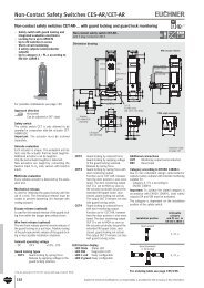
<strong>Safety</strong> <strong>System</strong> CES-AZRead head CET-AX-… Read head with guard locking and guard lock monitoring Up to category 4 High locking forces up to 6,500 N Integrated transponder coding Metal housingDesign and functionalityWith the read head CET in combination with an evaluation unit CES-AZ, EU-CHNER provides monitored guard locking based on non-contact transpondertechnology. This means that the switch can also be used on systems withovertraveling machine movements for personal protection.When closing the safety guard (hinged or sliding door), the spring-loadedtransponder in the actuator is inserted into the recess on the read head.The read head detects the closed safety guard in its guard locked position.The CES evaluation electronics enables the safety circuit when thesafety guard is locked.When the moving parts of the machine come to a standstill, the solenoidintegrated into the read head can be activated by a safe standstill monitoror by a timer relay. The solenoid's plunger then raises the spring-loadedtransponder, which allows the safety guard to be opened.Use of the read head even in extremely harsh environmentsDue to the extremely robust metal housing, the switch is suitable for theharshest ambient conditions and when guard locked achieves a lockingforce of 6,500 N – a characteristic that is advantageous particularly forheavy doors.With the safety guard closed, the CET provides around ± 5 mm of freedomof movement in all 3 directions (x, y, z direction) – even if the safety doordrops over time it will not be necessary to re-adjust the actuator.The insertion slide can be rotated in 90° steps. As a result the switch issuitable for doors hinged on the right and left.Different versionsAlong with the standard version with a single ramp, there is also the CETwith a double ramp that is perfectly suited to swing doors and rotary tables.That is, wherever the approach is from two sides and where the read headmust also be "passed over".As an option, <strong>EUCHNER</strong> also offers versions with escape release. Thisfeature enables people locked in to open the locked safety guard fromthe inside in an emergency.The range is supplemented by versions with different plug variants andfreely configurable LED control.Your advantages Robust die-cast zinc housing for harsh environments Suitable for heavy doors High protection against tampering Actuator with large freedom of movement No precise door adjustment necessary Low wiring effort High degree of protection IP67 Suitable for the highest safety requirementsSubject to technical modifications; no responsibility is accepted for the accuracy of this information.57
<strong>Safety</strong> <strong>System</strong> CES-AZRead head CET.-AX-… with guard locking and guard lock monitoring Read head with guard locking Locking force up to 6,500 N Up to category 4 / PL e according toEN ISO 13849-1Read head CET.-AX-…with plug connector M12Dimension drawingVersionCET.-AX-LRA-…Single ramp4230∅6.5 for screw M6DIN 1207/ISO 4762M12 x 11613,5LED 2greenLED 1redMechanical release167130For possible combinations see page 63For ordering table see page 61 ff.Approach directionHorizontalCan be adjusted in 90° stepsMechanical releaseIs used for releasing the guard locking with theaid of a tool. The mechanical release must besealed to prevent tampering (for example withsealing lacquer).Escape release (optional)Is used for the manual release of the guard lockingfrom within the danger area without tools.Wire front release (optional)The wire front release permits remote release ofthe guard locking via a pull rope. Flexible routingof the pull wire permits release of the guard lockingin inaccessible installation situations.The handle for the wire front release is notincluded. Please order separately (see page 62).Lockout mechanismThe lockout mechanism can be used to preventmaintenance personnel from being unintentionallylocked in the danger area, for example. In lockedposition, the lockout mechanism prevents activationof guard locking. The lockout mechanism canbe secured in locking position with up to threelocks. The mechanical release can still be used.Solenoid operating voltage DC 24 V +10%, -15%Guard locking types CET1 Closed-circuit current principleRelease by applying voltage to theguard locking solenoid. CET2 Open-circuit current principleGuard locking by applying voltageto the guard locking solenoid.Release by spring force.LED function display LED red illuminates when solenoid isswitched on or freely configurable LED green freely configurableCategory according to EN ISO 13849-1The category in accordance with EN ISO 13849-1is dependent on the evaluation unit and on theinstallation position (see table of possible combinationson page 63).±474,5115ActuatorCET-A-BWK-50XOrder separately153425Actuator CET-A-BWK-50Xfor read head CET-AX4 safety screwsM5x16 included2867,2Notes Special <strong>EUCHNER</strong> connection cables are requiredfor the connection (see page 69/70/72).Please take into account in the order! 2590Active faceread head52For connection cablessee page 68 The read head CET is only allowed to beoperated in conjunction with the actuatorCET-A-BWK-50X. The actuator must be orderedseparately.58Subject to technical modifications; no responsibility is accepted for the accuracy of this information.
<strong>Safety</strong> <strong>System</strong> CES-AZRead head CET…with escape releaseRead head CET…with 2 plug connectors M8Dimension drawingOrder no.102161103750111918Order no.102988103444109932M 8M 8M 12 x 11012Basic position forescape release14Release by pressing8416242075For connection cablessee page 6826,510,5For connection cablessee page 65/66Read head CET…with lockout mechanismRead head CET…with wire front releaseDimension drawingOrder no.111917111918Order no.On request4230,51408385Subject to technical modifications; no responsibility is accepted for the accuracy of this information.59
<strong>Safety</strong> <strong>System</strong> CES-AZWiring diagramsOrder no.095735100399102161103750104051106039111917111918Actuator-S1With plug connector M126CET1-AX-LRA-00-50X-SA095735UCM4LED2Order no.104062Actuator6-S1 CET1-AX-LRA-00-50L-SA104062ReadheadReadheadWith plug connector M12 and 2 freely configurableLEDsUCM54<strong>EUCHNER</strong>LED1LED2<strong>EUCHNER</strong>LED1LED283 2 10 V70V58 3 2 10 V7-A10VUBJSH1H11 H12-A10VUBJSH1H11 H12CES-AZ-AES-01B104770<strong>EUCHNER</strong>K2+K1+CES-AZ-AES-01B104770<strong>EUCHNER</strong>K2+K1+TSTO1DIA23 24 13 14Y1 Y2STSTO1DIA23 24 13 14Y1 Y2SOrder no.102988103444109932With 2 plug connectors M8X2.1-S1 CET1-AX-LRA-00-50X-SC102988UCMX2.4ActuatorReadhead<strong>EUCHNER</strong>LED1LED280 VX1.4 X1.1 X1.3 X2.3X2.2-A10VUBJSH1H11 H12CES-AZ-AES-01B104770<strong>EUCHNER</strong>K2+K1+TSTO1DIA23 24 13 14Y1 Y2S60Subject to technical modifications; no responsibility is accepted for the accuracy of this information.
<strong>Safety</strong> <strong>System</strong> CES-AZRead head CET.-AX-… with plug connector M12Terminal assignmentRead headPlug connector(view of connection side)PinFunctionWire colorconnection cable*CET1-AX-LRA-00-50X-SA095735CET1-AX-LDA-00-50X-SE100399CET1-AX-LRA-00-50F-SA With plug connector M1210216165 4CET1-AX-LDA-00-50F-SA10375073CET1-AX-LRA-00-50X-SF10405118 2CET1-AX-LRA-00-50X-SA-C2333-1119177111917For connection cable seepage 72CET1-AX-LRA-00-50F-SA-C2333-111918111918CET2-AX-LRA-00-50X-SA106039 2)With plug connector M12and 2 freely configurableLEDs1 H1, read head data wire WH2 H2, read head data wire BN3 SH, data wire screen (Screen)4 LED 2 freely configurable, 24 V YE5 0V GY6 UCM, U B/24 V solenoid PK7 0 V/GND solenoid BU8 Housing RD1 H1, read head data wire WH2 H2, read head data wire BN6543 SH, data wire screen (Screen)CET1-AX-LRA-00-50L-SA104062734 LED 2 freely configurable, 24 V YE5 LED 1 freely configurable, 24 V GY18 2For connection cable seepage 726 UCM, U B/24 V solenoid PK7 0 V/GND solenoid and LEDs BU8 Housing RD* Only for standard <strong>EUCHNER</strong> connection cableOrdering tableOrder no./itemClosed-circuitcurrent principleOpen-circuitcurrent principleSingle rampDouble rampEscape releaseWire front releaseLockout mechanism2 LEDs(1 freely configurable)2 LEDs(2 freely configurable)095735CET1-AX-LRA-00-50X-SA100399CET1-AX-LDA-00-50X-SE102161CET1-AX-LRA-00-50F-SA75 mm103750CET1-AX-LDA-00-50F-SA75 mm104051 1)CET1-AX-LRA-00-50X-SF111917CET1-AX-LRA-00-50X-SA-C2333-111917111918CET1-AX-LRA-00-50F-SA-C2333-11191875 mm106039 2)CET2-AX-LRA-00-50X-SA104062CET1-AX-LRA-00-50L-SA1) Plug connector can be rotated by 360°2) No German Social Accident Insurance or UL approvalSubject to technical modifications; no responsibility is accepted for the accuracy of this information.61
<strong>Safety</strong> <strong>System</strong> CES-AZRead head CET.-AX-… with 2 plug connectors M8Terminal assignmentRead headPlug connector(view of connection side)CET1-AX-LRA-00-50X-SCWith 2 plug connectors M8X1.4102988CET1-AX-LDA-00-50X-SC103444CET2-AX-LRA-00-50X-SCX1.3X2.2X2.1X1.1X2.4X2.3For connection cable seepage 69/70PinFunctionWire color connectioncable*X 1.1 H1, read head data wire BNX 1.3 H2, read head data wire WHX 1.4 SH, data wire screen BUX 2.1 UCM, U B/24 V solenoid BNX 2.2 0V WHX 2.3 0 V/GND solenoid BUX 2.4 LED 2 freely configurable, 24 V BK* Only for standard <strong>EUCHNER</strong> connection cableOrdering tableOrder no./itemClosed-circuitcurrent principleOpen-circuitcurrent principleSingle rampDouble rampEscape releaseWire front releaseLockout mechanism2 LEDs(1 freely configurable)2 LEDs(2 freely configurable)102988CET1-AX-LRA-00-50X-SC103444CET1-AX-LDA-00-50X-SC109932 1)CET2-AX-LRA-00-50X-SC1) No German Social Accident Insurance or UL approvalOn requestAccessoriesOrdering tableDesignation Version/usage Order no./itemActuator for CET…<strong>Safety</strong> screws M5 x 16Handle for wire front releaseIncl. safety screwsSpare screws for actuator CET-A-BWK-50XPackaging unit: 100 ea.For read head CET-AX with wire front release096327CET-A-BWK-50X073456M5x16/V100099795Handle for wire front release62Subject to technical modifications; no responsibility is accepted for the accuracy of this information.
<strong>Safety</strong> <strong>System</strong> CES-AZTechnical data for read head CET…<strong>Safety</strong> switchesParameter Value Unitmin. typ. max.GeneralMaterial, rampStainless steelMaterial, read head housingDie-cast aluminumInstallation positionAny (recommendation: actuating head downward)Degree of protection according to IEC 60529IP67 (screwed tight with the related mating connector)Mechanical life1 x 10 6 operating cyclesAmbient temperature -20 - +55 °CActuator approach speed, max. 20 m/minLocking force, max. 6,500Locking force F ZhNFin acc. with GS-ET-19Zh= F max= 5,0001.3Mass Approx. 1.0 kgFreedom of movement X, Y, Z (in guard locked position) X and Y: ± 5; Z: ± 4 mmSwitching frequency1 Hz(This value can vary depending on the evaluation unit used.See system documentation of the related evaluation unit)<strong>Co</strong>nnectionM12 plug connector, 8-pin / 2 M8 plug connectors, 3- and 4-pinCable length - - 25 mRated insulation voltage U i50 VRated impulse withstand voltage U imp0.8 kVSolenoid<strong>Co</strong>nnectionReverse polarity protectedSolenoid operating voltage 24 +10%, -15% V DCSolenoid power consumption 12 WDuty cycle 100 %ActuatorParameter Value Unitmin. typ. max.GeneralHousing materialStainless steelInstallation positionActive face opposite read headDegree of protection according to IEC 60529IP67Mechanical life1 x 10 6 operating cyclesAmbient temperature -20 - +55 °CLocking force, max. 6,500 NMass Approx. 0.25 kgStroke max. 15 mmPower supplyInductive, via read headLEDParameter Value Unitmin. typ. max.General<strong>Co</strong>nnection voltage 24 ± 15% VCurrent consumption, max. 6 mAImportant:The maximum safety category that can be achieved in accordance with EN ISO 13849-1 is dependent on the installation position of the safety switchand the evaluation unit used. Pay attention to the table below during the selection of the evaluation unit.<strong>Co</strong>mbination options(extract only; you will find further possible combinations in the system manual for the evaluation unit used)Read head/order numberEvaluation unit/order numberInstallation positionAchievable category and PL accordingto EN ISO 13849-1Head upward3 / PL eIn this installation position the PFH dvalue of the system (evaluation unit +read head) decreases to 4.29 x 10 -8CET.-AX-…CES-AZ-.ES-…Head downwardor horizontal4 / PL eIn this installation position the PFH dvalue for the system (evaluation unit +read head) is the same as that for theevaluation unitSubject to technical modifications; no responsibility is accepted for the accuracy of this information.63
<strong>Safety</strong> <strong>System</strong> CES-AZ<strong>Co</strong>nnection cables with plug connectors For read heads with M5 plug connectorfor CES-A-LSP-..SBstraight, M5 socket, 3-pinDimension drawing67,54 (WH)1 (BN)27,53(Schirm/Screen)2 (NC)View ofconnection side3,7Cable end sleeves30“l”Ordering tableUse Plug connector Type of cable Cable length [m] Order No./itemForread headsCES-A-LSP-..SBStraightVPVC cable51020105555C-M05F03-02X014PV05,0-ES-105555105556C-M05F03-02X014PV10,0-ES-105556105559C-M05F03-02X014PV20,0-ES-105559Technical dataParameterValuemin. typ. max.UnitPlug connector3-pin M5 female connector, straight<strong>Co</strong>nnectionScrew terminal, knurled nut not connected to cable screen<strong>Co</strong>nductor cross-section 2 x 0.14 screened mm²Material, outer sheath PVC ∅ 3.7 mm mmCable length Max. 25 (taking into account the switching distance) m64Subject to technical modifications; no responsibility is accepted for the accuracy of this information.
<strong>Safety</strong> <strong>System</strong> CES-AZ For read heads with M8 plug connectorfor CES-A-L…/CEM-A-L…/CET-AX/CKSstraight, M8 socket, 3-pinfor CES-A-L…/CEM-A-L…/CET-AX/CKSangled, M8 socket, 3-pinDimension drawing∅1018,510"l"22,531∅4,3...4,63030"l"∅1026,54 Schirm/Screen1 (BN)4 Schirm/Screen1 (BN)3 (WH)3 (WH)View ofconnection sideView ofconnection side∅4,3...4,6Cable end sleevesCable end sleevesOrdering tableUse Plug connector Type of cable Cable length [m] Order No./itemForRead headsCES-A-L…/CEM-A-L…/CET-AX-L…-SC/CKS…-SCTechnical dataStraightStraightAngledVPVC cablePPUR cableVPVC cablePPUR cable35102025510152025102510077935C-M08F03-02X025PV03,0-ES-077935077793C-M08F03-02X025PV05,0-ES-077793077767C-M08F03-02X025PV10,0-ES-077767077716C-M08F03-02X025PV20,0-ES-077716077717C-M08F03-02X025PV25,0-ES-077717084762C-M08F03-02X025PU05,0-ES-084762084763C-M08F03-02X025PU10,0-ES-084763084764C-M08F03-02X025PU15,0-ES-084764084765C-M08F03-02X025PU20,0-ES-084765084766C-M08F03-02X025PU25,0-ES-084766084701C-M08F03-02X025PV10,0-ES-084701099998C-M08F03-02X025PV25,0-ES-099998098590C-M08F03-02X025PU10,0-ES-098590ParameterValuemin. typ. max.UnitPlug connector3-pin M8 female connector, straight<strong>Co</strong>nnectionScrew terminal, knurled nut not connected to cable screen<strong>Co</strong>nductor cross-section 2 x 0.25 screened mm²Material, outer sheath PVC ∅ 4.6 or PUR ∅ 4.3 (PUR cables are suitable for drag chains) mmCable length Max. 25 (taking into account the switching distance) mSubject to technical modifications; no responsibility is accepted for the accuracy of this information.65
<strong>Safety</strong> <strong>System</strong> CES-AZ<strong>Co</strong>nnection cables with plug connectorsFor solenoid operating voltage read head CEM/CET-AXstraight, M8 socket, 4-pinFor solenoid operating voltage read head CEM/CET-AXangled, M8 socket, 4-pinDimension drawing∅1018,510"l"22,531∅4,3...5,230"l"∅4,3...5,230∅1026,54 (BK) 2 (WH)4 (BK)82 (WH)63 (BU)1 (BN)3 (BU)1 (BN)View ofconnection sideView ofconnection sideCable end sleevesCable end sleevesOrdering tableUse Plug connector Type of cable Cable length [m] Order No./item5088813C-M08F04-04X025PV05,0-ES-088813VPVC cable1015088814C-M08F04-04X025PV10,0-ES-088814088815C-M08F04-04X025PV15,0-ES-088815Forsolenoid operating voltageread headsCEM-A-L…/CET-AX-L…-SCStraight255095035C-M08F04-04X025PV25,0-ES-095035116049C-M08F04-04X034PU05,0-ES-116049UPUR cable10116050C-M08F04-04X034PU10,0-ES-11605020116051C-M08F04-04X034PU20,0-ES-116051AngledVPVC cable10084703C-M08F04-04X025PV10,0-ES-084703Technical dataValueParameterUnitmin. typ. max.Plug connector4-pin M8 female connector<strong>Co</strong>nnectionScrew terminal<strong>Co</strong>nductor cross-section PVC: 4 x 0.25 / PUR: 4 x 0.34 mm²Material, connector housingPVC: PUR black / PUR: TPU blackMaterial, outer sheath PVC ∅ 5.0 / PUR ∅ 4.7 mmMaterial, union nutCuZn nickel-platedStatic bending radius 5 x cable - -66Subject to technical modifications; no responsibility is accepted for the accuracy of this information.
<strong>Safety</strong> <strong>System</strong> CES-AZFor LED indicator read head CEM-A-LH10…straight, M8 plug, 4-pinFor LED indicator read head CEM-A-LH10…angled, M8 plug, 4-pinDimension drawingM8x124,8513,63031"l"37∅4,3...5,250M8x126,58,82 (WH)4 (BK)2 (WH)4 (BK)1 (BN) 3 (BU)1 (BN) 3 (BU)View ofconnection sideView ofconnection side"l"∅4,3...5,2Ordering tableUse Plug connector Type of cable Cable length [m] Order No./item2088841C-M08M04-04X025PV02,0-ES-088841ForLED indicatorread head CEM-A-LH10…StraightVPVC cable51015088842C-M08M04-04X025PV05,0-ES-088842088843C-M08M04-04X025PV10,0-ES-088843088844C-M08M04-04X025PV15,0-ES-088844AngledVPVC cable10084705C-M08M04-04X025PV10,0-ES-084705Technical dataValueParameterUnitmin. typ. max.Plug connector4-pin M8 plug<strong>Co</strong>nnectionScrew terminal<strong>Co</strong>nductor cross-section 4 x 0.25 mm²Material, connector housingPUR blackMaterial, outer sheath PVC ∅ 5.0 mmMaterial, union nutCuZn nickel-platedBending radius Min. 10 x sheath diameter mmSubject to technical modifications; no responsibility is accepted for the accuracy of this information.67
<strong>Safety</strong> <strong>System</strong> CES-AZ<strong>Co</strong>nnection cables with plug connectors For read heads withM12 plug connectorfor CET…straight/angled, M12 socket, 8-pinThese special connection cables are needed forthe connection of the CET to a CES evaluationunit. Please take into account in the order!Interference is prevented by special screening.Important<strong>Co</strong>nnection cables are not allowed to be extended.NoteThe connection cables with PUR sheath are suitablefor drag chains with a minimum bendingradius of 60 mm (10 times the cable diameter).Dimension drawingYE 4Screen 3BN 2View ofconnection sideRD 8∅ 14,5M12 x 15 GY6 PK7 BU1 WH"l"10,5∅5,8...6WHBNScreenconnected to pin 3Ordering tableUse Sheath Plug connector Cable length [m] Order no.10099633C-M12F08-07X025PV10,0-MA-099633Straight20099634C-M12F08-07X025PV20,0-MA-099634for CET…<strong>Co</strong>nnection cable7 x 0.25 mm²with plug connector M12and flying leadPVCAngled251020103115C-M12F08-07X025PV25,0-MA-103115100456C-M12F08-07X025PV10,0-MA-100456105071C-M12F08-07X025PV20,0-MA-105071PURStraight1025102218C-M12F08-07X025PU10,0-MA-102218103782C-M12F08-07X025PU25,0-MA-10378268Subject to technical modifications; no responsibility is accepted for the accuracy of this information.
<strong>Safety</strong> <strong>System</strong> CES-AZTechnical dataValueParameterUnitmin. typ. max.Plug connector8-pin M12 female connector<strong>Co</strong>nnectionScrew terminal<strong>Co</strong>nductor cross-section 7 x 0.25 mm²Material, connector housingTPU, self-extinguishingMaterial, union nutCuZn nickel-platedMaterial, outer sheathSee ordering tableBending radiusmin. 10 x cable diameterSubject to technical modifications; no responsibility is accepted for the accuracy of this information.69
<strong>Safety</strong> <strong>System</strong> CES-AZPlug connector and connection set Plug connector for extending theconnection cable For read heads CES-A-L…/CEM-A-L…<strong>Co</strong>upling socket3-pin + PEFemale connector3-pin + PEUsing <strong>EUCHNER</strong> couplings/plug connectors,the user can cut the read head cable to size onsite at any point and connect the couplings/plugconnectors.Dimension drawing<strong>Co</strong>upling socketFemale connectorNoteThe connection cable for the read head can onlybe extended using these self-assembly couplings/plug connectors under the following conditions: The total maximum cable length is 25 m, takinginto account the switch-on distance. The cable specified by <strong>EUCHNER</strong> must beused for the extension (screened, strand crosssection2 x 0.25 mm²). The plug connector housing must be electricallyisolated from the machine ground.∅ 19Pg9SW16621 = BN H13 = WH H2 SH (screen)106Inserted14432Pg9∅ 19,5SW16View connection side female connectorOrdering tableDesignation Version Order No./itemKD4C18513-pin + PEBS4C18513-pin + PE<strong>Co</strong>upling socket for female connector BS4C1851Female connector for coupling socket KD4C1851077434KD4C1851077435BS4C1851Technical dataParameterHousing materialDegree of protection acc. to EN 60529Valuemin. typ. max.CuZn, matt chromium-platedIP65 (inserted)Unit Plug-in connection terminalsfor evaluation unit CES-AZOrdering tableDesignation Version Order No./item<strong>Co</strong>nnection setfor evaluation unitCES-AZ-…-01B<strong>Co</strong>nnection setfor evaluation unitCES-AZ-…-02B<strong>Co</strong>nnection setfor evaluation unitCES-AZ-…S-04BPlug-in screw terminalsPlug-in spring terminalsPlug-in screw terminalsPlug-in spring terminalsPlug-in screw terminalsPlug-in spring terminals104756CES-EA-TC-AK04-104756112631CES-EA-TC-KK04-112631104771CES-EA-TC-AK06-104771112630CES-EA-TC-KK06-112630104776CES-EA-TC-AK08-104776112629CES-EA-TC-KK08-11262970Subject to technical modifications; no responsibility is accepted for the accuracy of this information.
<strong>Safety</strong> <strong>System</strong> CES-AZMounting plate CET Mounting plate for read head CET forhinged or sliding doors Suitable for aluminum profiles40 … 45 mm Horizontal and vertical mounting Made of aluminum Suitable for CET with escape releaseMounting plate EMP-L-CETfor read head CETDimension drawing82654237Mounting plate EMP-B-CETfor actuator CET45205207For M6 screwEN ISO 4762For M5 screw(12x)203913822,5586,5For M6 screw(12x)27Profile marking 45 x 459,5Material thickness 10 mmMaterial thickness 10 mmOrdering tableDesignation Use Order No./itemMounting plate EMP-L-CETMounting plate EMP-B-CETfor read head CETfor actuator CET106695EMP-L-CET106694EMP-B-CETInstallation example mounting plates EMP-.-CET12,5454540 15 4045 15 4540 15 40Subject to technical modifications; no responsibility is accepted for the accuracy of this information.71
<strong>Safety</strong> <strong>System</strong> CES-AZ<strong>Safety</strong> screwsOrdering tableFixing material/screw sizeInstallation material forBosch profiles with 8-mm slotInstallation material forBosch profiles with 10 mm slotInstallation material forITEM profiles with 8-mm slot<strong>Safety</strong> screwsM4 x 14(small head)<strong>Safety</strong> screwsM5 x 16Version/usageRead heads CES-A-LSPandactuators CES-A-BSPRead heads CES-A-LSPandactuators CES-A-BSPRead heads CES-A-LSPandactuators CES-A-BSPRead headsCES-A-LN…, CES-A-LC…, CES-A-LQ…andactuatorsCES-A-BB…, CES-A-BCA, CES-A-BQ…Read heads CEM-A-LE… and actuatorsCET-A-BWK, CEM-A-B…Packaging unit[qty.]Order no.2+2 1066332+2 1066342+2 10663520 071863100 07345672Subject to technical modifications; no responsibility is accepted for the accuracy of this information.
<strong>Safety</strong> <strong>System</strong> CES-AZMiscellaneous accessories <strong>Co</strong>ver for read head CET Double ramp for safety switch CET<strong>Co</strong>verWith the CET cover, tampering with the read headCET is effectively prevented.The cover prevents the use of simple tools tomanually press up the actuator.<strong>Co</strong>verfor read head and actuator CET<strong>Co</strong>ver for door hinge on left mirror image8770207060641307,52Ø 6,5 (2x)Double rampThe ramp can be approached from two sides. Itcan be passed over, e.g. for sliding doors.Double rampfor read head CETOrdering tableDesignation Use Version Order No./item<strong>Co</strong>verDouble rampfor read head CET and actuator CETfor safety switch CETdoor hinge rightdoor hinge left098808CET cover right098807CET cover left114091Double ramp for CET74Subject to technical modifications; no responsibility is accepted for the accuracy of this information.
<strong>Safety</strong> <strong>System</strong> CES-AZ Inrush current limiting module PM-SCLVery high currents are produced on power up ifcapacitive loads are switched; these currentscause increased wear on electromagnetic switchingcontacts. The PM-SCL module limits the inrushcurrent for approx. 100 ms and protects theswitching contacts.Inrush current limiting module PM-SCLDimension drawing186264Block diagram and connection example+ DC 24 V CES0 Vread head+ 24 V 0 V H11 H12SH1CES1314 23 24B/CAPM-SCLmoduleDL+InputInputInputInputI/O modulesupplySPS /PLC0 VOrdering tableDesignation Version Order No./itemInrush current limiting module PM-SCLTechnical datafor CES evaluation units096945PM-SCL-096945ParameterValuemin. typ. max.UnitHousing material Polyamide UL 94.V2Degree of protection acc. to EN IEC 60529IP20Ambient temperature at U B= DC 24 V -20 - +55 °CAtmospheric humidity 80%, not condensingStorage temperature -25 - +70 °CDegree of contamination (external, according to EN 60947) 2MountingMounting rail 35 mm according to DIN EN 50022Mounting rail 32 mm according to DIN EN 50035Mass Approx. 0.04 kg<strong>Co</strong>nnection<strong>Co</strong>nnection terminals<strong>Co</strong>nductor cross-section 0.14 … 2.5 mm²Switching voltage 15 - 40 V DCSwitching current (semiconductor output) 1 - 3,000 mAInternal fuse (fine-wire fuse 20 x 5 mm)6.3 A slow blow; breaking capacity min. 1 kAInrush current limiting 60 mADuration of limiting (at switch-on voltage 24 V) 75 - 120 msSwitching frequency - - 1 HzLoad capacitance on which interference can be suppressed(at input voltage 24 V)- - 40 μFVoltage drop after the limiting time has elapsed - 1.16 - VModule current consumption - - 20 mASubject to technical modifications; no responsibility is accepted for the accuracy of this information.75
<strong>Safety</strong> <strong>System</strong> CES-AZ76Subject to technical modifications; no responsibility is accepted for the accuracy of this information.
<strong>Safety</strong> <strong>System</strong> CES-FD<strong>Non</strong>-contact safety system CES-FD-… Evaluation of signals in the field <strong>Co</strong>nnection of CES read heads <strong>Co</strong>nnection to the ET200s and ET200pro Familiar <strong>EUCHNER</strong> AP interfaceFunctional descriptionField evaluation units series CES-FD-AP make it possible to evaluate CESread heads in the field.The safety outputs on the field evaluation units are connected to themachine control.The system meets the following safety requirements: <strong>Safety</strong> category 4, PLe according to EN ISO 13849-1 Redundant design of the circuit in the unit with self-monitoring This means that the safety system still functions even if an internalcomponent fails The switch state of the semiconductor outputs is continuously monitoredinternally Short circuit detection at the safety outputs by clocked signalsThe following switch-on condition applies to the safety outputs FO1Aand FO1B: <strong>Safety</strong> guard closedThe system consists of three components: coded actuator (transponder), field evaluation unit and read head.The read head is connected to the field evaluation unit and reads theactuator code.Every <strong>EUCHNER</strong> actuator supplied has an electronic coding (unique coding)that is read by the read head. Only if a correct coding is detecteddoes the system accept the actuator. The code in an actuator cannot bereprogrammed.Unlike systems with unique code detection, on multicode systems aspecific code is not requested but instead it is only checked whetherthe actuator is of a type that can be detected by the system (multicodedetection). There is no exact comparison of the actuator code with thecode defined in the safety switch (unique code detection).The read head is fastened to the fixed part of the safety guard.The actuator attached to the movable part of the safety guard is movedtowards the read head by closing the door. The read head is connectedto the field evaluation unit. When the switch-on distance is reached, poweris supplied to the actuator by the read head by induction and data canbe transferred.If a permissible code is detected, the safety outputs are released.Due to the combination of dynamic polling of the actuator and the redundant,diverse design of the safety electronics with the two feedbacksafety outputs, the safety switch will enter the safe state with everydetectable fault.When the safety guard is opened, the safety outputs switch off the safetycircuit and the monitoring output OD is switched off. The state of the safetyoutputs is monitored internally by two microprocessors.If faults are detected, the safety circuit is switched off and the DIA LEDilluminates. In case of devices with a monitoring output OI, the output isswitched on.The field evaluation unit has a redundant switching design with selfmonitoring.This means that the safety system is still effective even if acomponent fails.The system is designed so that failures will not result in the loss of thesafety function. The occurrence of failures is detected by cyclic selfmonitoringat the latest on the next demand to switch on the safetyoutputs (e.g. on starting).If the safety door with the actuator should settle over time, the actuatorcan drift out of the read head operating distance. The device recognizesthis situation and indicates that the actuator is in the limit range. Thisallows the safety door to be readjusted in time.Your advantages Maximum safety with cat. 4/PLe Minimal wiring effort Small space requirement No additional DIN rail mounted evaluation unit requiredDirect connection to decentralized peripheralsystems (e.g. ET200pro)PLCdecentralizedperipherye.g. ET 200proDI21 54UB1FO1A20V3FO1B4X1: M12 plug-connector(5-pin)CES-FD-AP-...-.SI-...3 1n.c.5254<strong>Co</strong>nnection example:Version for connection to decentralized peripheral equipment3DO<strong>Co</strong>nnection to safe control systems or safety relaysDo not use a control system or safety relay with pulsing for monitoringshort circuits or switch off the pulsing function in these devices. Theswitch generates its own clock signals on the output lines FO1A/FO1B.A downstream device must tolerate these test pulses, which may have alength of up to 0.4 ms.The inputs on the downstream device must be suitable for positiveswitchingdevices (pnp outputs), as the two outputs on the safety switchdeliver a level of +24 V in the switched-on state.CES-FDSubject to technical modifications; no responsibility is accepted for the accuracy of this information.77
<strong>Safety</strong> <strong>System</strong> CES-FDField evaluation unit1Cat.4PLeCES-FD-AP-.-01-USI-… No series connection Pulsing for short circuit detection Available in the unicode and multicode variants(see page 82)78Subject to technical modifications; no responsibility is accepted for the accuracy of this information.
<strong>Safety</strong> <strong>System</strong> CES-FDRead headActuatorCES-A-LMN-SC Cylindrical design M12 M8 plug connector(see page 84)CES-A-BMB Cylindrical design M12(see page 86)CKS-A-L1B-SC-113130 Key adapter for installationin control panels M8 plug connector(see page 87)CKS-A-BK1-RD-113461 Key for key adapter CKS(see page 87)Subject to technical modifications; no responsibility is accepted for the accuracy of this information.79
113461FR<strong>Safety</strong> <strong>System</strong> CES-FD<strong>Co</strong>mponent overview for the non-contact safety system CES-FD…Extension cables Field evaluation unit Read heads Actuator BoltCES-A-LMN-SCCES-A-BMB-CES-FD-AP-.01--USI-…page 84page 86page 82page 82CKS-A-L1B-SC-113130CKS-A-RD-113461CKS-page 87page 8780Subject to technical modifications; no responsibility is accepted for the accuracy of this information.
<strong>Safety</strong> <strong>System</strong> CES-FDPossible combinations for CES componentsTo give you a quick overview of which CES components can be combined with each other, there is a combination table for each evaluation unit andfor each safety switch. The table will answer the following questions: Which actuator can be read by the selected safety switch? What is the operating distance of this combination? Which type of guard locking can be realized with the selected combination?Important: Only typical values are listed in the table. The minimum and maximum values are listed in the technical data for the relatedproduct.15 <strong>Co</strong>mbination possible, typ. switch-on distance 15 mmKey to symbols<strong>Co</strong>mbination possible, guard locking for process protection<strong>Co</strong>mbination possible, guard locking for personal protection<strong>Co</strong>mbination not permissible<strong>Non</strong>-contact safety switches CES-FDActuatorField evaluation unitRead headCES-A-BMB077791CKS-A-BK1-RD113461CES-FD-AP-.-01-USI-…CES-A-LMN-SC077790CKS-A-L1B-SC1131305-Subject to technical modifications; no responsibility is accepted for the accuracy of this information.81
<strong>Safety</strong> <strong>System</strong> CES-FDField evaluation unit CES-FD-AP-… Evaluation of signals in the field <strong>Co</strong>nnection of CES read heads <strong>Co</strong>nnection to the ET200s and ET-200pro Familiar <strong>EUCHNER</strong> AP interfaceField evaluation unit CES-FD-AP-…Dimension drawing<strong>Co</strong>nnection cable for control systemwith M12 plug connector, 5-pin<strong>Co</strong>nnection cable for read headwith M8 plug connector, 3-pinCat.4PLeCable length:1,000 mm012 - 0,2Cable length:200 mmFor possible combinations see page 8136,595LED status indication4,5Fastening lug withreinforcement plateShort circuit monitoringThe switch generates its own clock signal on theoutput lines FO1A/FO1B.Pay attention to this aspect when connecting tocontrol systems and relays.Z1119,530XAvailable coding options (see page 5) Unicode evaluation Multicode evaluationCategory according to EN ISO 13849-1Due to two redundant design semiconductoroutputs (safety outputs) with internal monitoringsuitable for: Category 4 / PL e according to EN ISO 13849-1Important: To achieve the stated category inaccordance with EN ISO 13849-1, both safetyoutputs (FO1A and FO1B) must be evaluated.LED indicatorSTATE Status LEDDIA Diagnostics LEDM12 plugconnector5-pin23<strong>Co</strong>ding lug4155,575+0,585 0Pin Designation Description Wire color1 H1 Data wire BN3 H2 Data wire WH4 SH Screen -5-pinPin5-pin,pin 5notused6M8 plugconnector,3-pin31 4Designation Description Wire color1 1 UB Power supply DC 24 V BN2 2 FO1A <strong>Safety</strong> output, channel 1 WH3 3 0V Ground DC 0 V BU4 4 FO1B <strong>Safety</strong> output, channel 2 BK5 - OD Monitoring output GY+UB0VFO1AFO1BODX1.1X1.3X1.2X1.4X1.5+UB0VFO1AFO1Bn.c.X1.1X1.3X1.2X1.4X1.5<strong>Safety</strong> screws see page 89. <strong>Co</strong>nnection cables see page 156 ff.Ordering tableSeriesCES-FD-AP-U-01-…UnicodeCES-FD-AP-M-01-…Multicode<strong>Co</strong>nnection cablewith M12 plug connector, 5-pinCategory and PLacc. to EN ISO 13849-14 / PL 34 / PL 3Extensionfor read head cable with M8 plug connector, 3-pinVersion<strong>Co</strong>nnection cable withM12 plug connector,pin 5 not assigned<strong>Co</strong>nnection cable withM12 plug connector,pin 5 not assignedOrder no./item119865CES-FD-AP-U-01-USI-119865115534CES-FD-AP-M-01-USI-1155345 m, PVC 10018310 m, PVC 10018420 m, PVC 1001850.4 m, PUR 11546482Subject to technical modifications; no responsibility is accepted for the accuracy of this information.
<strong>Safety</strong> <strong>System</strong> CES-FDTechnical data for field evaluation unit CES-FD-AP-…ParameterValuemin. typ. max.UnitHousing materialPlastic PBTDimensions 95 x 30 x 12 mmMass 0.04 kgAmbient temperature at U B= DC 24 V- With connection cable with M12 plug connector- <strong>Co</strong>nnection cable laid rigidly -20 - +65- <strong>Co</strong>nnection cable movable -0 - +65Storage temperature -20 - +70Degree of protectionIP67<strong>Safety</strong> classIIIDegree of contamination 3Installation positionany<strong>Co</strong>nnection- Evaluation- Read headOperating voltage U B(reverse polarity protected, regulated,residual ripple < 5%)<strong>Co</strong>nnection cable with plug connector M12x1, 5-pin<strong>Co</strong>nnection cable with plug connector M8x1, 3-pin24 ± 15% (PELV) V DCCurrent consumption 45 mASwitching load according to DC 24 V, class 2External fuse (operating voltage) 0.25 - 1.5 A<strong>Safety</strong> outputs FO1A/FO1BSemiconductor outputs, p-switching, short circuit-proof- Output voltage U(FO1A)/U(FO1B) 1)HIGHU(FO1A)U B-1.5 - UHIGHU(FO1B)BV DCLOW U(FO1A)/U(FO1B) 0 1Switching current per safety output 1 - 150 mAUtilization category according to EN 60947-5-2DC-13 24 V 150 mACaution: outputs must be protected with a free-wheeling diode in case of inductiveloads.Off-state current I r≤ 0.25 mAMonitoring output OD 2)Semiconductor output p-switching, short circuit-proof- Output voltage 0.8 x U B- U BV DC- Max. load - - 50 mARated insulation voltage U i- - 75 VRated impulse withstand voltage U imp- - 1.5 kVResilience to vibration acc. to EN IEC 60947-5-2Switching frequency - - 1 HzRepeat accuracy R ≤ 10 %EMC protection requirements according to EN 60947-5-3Reliability values according to EN ISO 13849-1Category 4Performance Level (PL)ePFH d4.5 x 10 -9 / hMission time 20 years1) The device tolerates voltage interruptions of up to 10 ms.2) Values at a switching current of 50 mA without taking into account the cable lengths.°CSubject to technical modifications; no responsibility is accepted for the accuracy of this information.83
<strong>Safety</strong> <strong>System</strong> CES-FDRead head CES-A-LMN-SC Cylindrical design M12 M8 plug connector (snapactionand screw terminals)Read head CES-A-LMN-SCM8 plug, 3-pinDimension drawingRead distances435in inserted state17321)19,7M 12x1mFor possible combinations seepage 81Attention:The operating distance may varydepending on the substrate materialand installation situation.Center offset51)830M8x1Active faceImportant:Actuators must be ordered separately!See page 86.1) Metal-free zone37For connection cablesee page 82Terminal assignmentTypical operating distanceY8ScreenBNWHH11 H12 SH1CES-AZ…413Read head8 62468X64262 4 6 8Z8A minimum distance of s = 1.2 mm must be maintained.Ordering tableSeries <strong>Co</strong>nnection Version Order no./itemCES-A-LMN-SCSCM8 plug connectorHousing M12077790CES-A-LMN-SC84Subject to technical modifications; no responsibility is accepted for the accuracy of this information.
<strong>Safety</strong> <strong>System</strong> CES-FDTechnical data for read head CES-A-LMN-SC (in combination with CES-FD)Parameter Value Unitmin. typ. max.Housing materialNickel-plated CuZn housing sleevePlastic PBT GF20 capDimensions M12 x 1, length 38 mmMass 0.2 kgAmbient temperature°C- CES-A-LMN-SC -20 - +70Ambient pressure(only of active face in installed condition)- - 10 barDegree of protectionIP67Installation positionAnyMethod of operationInductivePower supplyVia evaluation unitCable length - - 0.7 mIn combination with actuator CES-A-BMBOperating distance for center offset m = 0 1)- Assured switch-off distance S ar- - 10Cable length l = 0 to 15 m- Switch-on distance - 5 -- Assured switch-on distance S ao3.4 - -- Switching hysteresis 0.05 0.2 -<strong>Co</strong>nnectionM8 plug connector (snap-action and screw terminals), 3-pin1) These values apply to surface installation of the read head in steel.mmSubject to technical modifications; no responsibility is accepted for the accuracy of this information.85
<strong>Safety</strong> <strong>System</strong> CES-FDActuator CES-A-BMB Cylindrical design M12 x 0.75Actuator CES-A-BMBDimension drawing0,80M12x0,75116Active faceFor possible combinations see page 81Insertion tool12,3 +0,12-0,06Insertion toolWith the aid of the insertion tool, the actuatorCES-A-BMB (cylindrical design) can be screwedinto a prepared M12 x 0.75 thread in the safetydoor.t = 0,611,1 +0,12-0,061,515Ordering tableSeries <strong>Co</strong>mment Version Order no./itemCES-A-BMB077791CES-A-BMBInsertion tool For actuator CES-A-BMB 037662Technical dataValueParameterUnitmin. typ. max.Housing materialStainless steelDimensions M12 x 0.75, depth 6 mmMass 0.002 kgAmbient temperature -25 - +70 °CAmbient pressure(only applies if the pressure acts on all sides of the actuator)- - 10 barDegree of protectionInstallation positionPower supplyIP67Active face opposite read headInductive via read head86Subject to technical modifications; no responsibility is accepted for the accuracy of this information.
<strong>Safety</strong> <strong>System</strong> CES-FDKey adapter CKS Key adapter with integrated CES readhead LED indicator Simple connection via M8 plug connector High degree of protection IP67Key adapter CKSDimension drawing40LEDKey adapter70,5max. 4 mmPlug connector M883757667For possible combinations see page 818M41,5 (Rubber seal)Screw clamp element50 108432Cable outlet, angled plug connectorFor connection cablesee page 82Key CKSImportant: Key adapter CKS must not be usedas a lockout mechanism in combination withmulticode evaluation.The key is not included with the key adapterand must be ordered separately.Dimension drawing40113461CKSFR∅ 25,4∅ 31Active face(front and rearsides)5Wiring diagramBNWH431H11 H12 SH1View of M8 plug connectorof key adapterEvaluation unitCESOrdering tableSeries Version Order no./itemCKS-A-L1B-SC-113130CKS-A-BK1-RD-113461Key adapter CKS (including screw clamp elements)Key CKS (color red)113130CKS-A-L1B-SC-113130113461CKS-A-BK1-RD-113461Subject to technical modifications; no responsibility is accepted for the accuracy of this information.87
<strong>Safety</strong> <strong>System</strong> CES-FDTechnical data for key adapter CKS (in combination with CES-FD)ParameterValuemin. typ. max.UnitKey adapterHousing materialPlastic (PA 6 GF30)Mass 0.13 kgAmbient temperature -20 - +70 °CDegree of protection according to IEC 60529IP67(in installed state)Installation positionOn the frontMounting cut-out according to DIN 43700 33 x 68 mmOperating distance 1)Assured switch-off distance s ar- - 35mmAssured switch-on distance s ao2 - -Switching hysteresis - 1 -<strong>Co</strong>nnection to evaluation unitPlug connector M8(male socket, 3-pin)Cable length - - 0.7 mLED indicatorwhite: valid key detectedKeyHousing materialPlastic (PC)Mass 0.004 kgDegree of protection according to IEC 60529IP67Ambient temperature -20 - +70 °CPower supplyInductive via read head1) Referred to the stop of the inserted key88Subject to technical modifications; no responsibility is accepted for the accuracy of this information.
<strong>Safety</strong> <strong>System</strong> CES-FD<strong>Safety</strong> screwsOrdering tableFixing material/screw size<strong>Safety</strong> screwsM4 x 14(large head)Version/usageField evaluation unitCES-FD-AP-M-01-USI-115534Packaging unit[qty.]Order no.100 086232Subject to technical modifications; no responsibility is accepted for the accuracy of this information.89
<strong>Safety</strong> <strong>System</strong> CES-FD90Subject to technical modifications; no responsibility is accepted for the accuracy of this information.
<strong>Safety</strong> Switches CES-A-.5<strong>Non</strong>-contact safety switches CES-A-C5…/CES-A-W5… Standard housing according to IEC/EN 60947-5-2, IP67 Read head and evaluation electronics integrated in housing Semiconductor output <strong>Co</strong>nnection of the safety circuit using M12 plug connector Unicode and multicode switchesFunctional descriptionThe <strong>Co</strong>ded Electronic <strong>Safety</strong> switch CES consists of two components: <strong>Co</strong>ded actuator <strong>Safety</strong> switchThe device described in this section is integrated with the read head in astandard housing according to IEC/EN 60947-5-2.Thanks to the high degree of protection IP67, this switch can be useddirectly on the safety guard in a very harsh environment. Semiconductortechnology allows for a compact design of the evaluation unit and wearfreeswitching with a theoretically unlimited number of operating cycles.The information from the coded actuator is read by the device and processedat the same point. The transfer of static signals (information onwhether door open or closed) to the higher level switchgear permits theuse of connecting cables up to 300 m long with the system.Serial wiring, i.e. the cascading of several devices, is possible. This featuremakes it possible for you to implement decentralized wiring concepts withthe safety switch CES.Specifically, the major advantage of the system is that the positioning ofthe evaluation electronics directly at the safety guard saves space in thecontrol cabinet.The system operator can read the current state of the safety switch onthe two LED indicators (one with double function). If the actuator is in theoperating distance, the OUT LED illuminates yellow. Even a possible faultin the device is indicated by a red LED. If servicing is required, the safetyswitch connected with an M12 plug connector can be replaced in seconds.The required approach direction can also be set quickly on the compacthousing. After two fastening screws have been undone, the active faceof the read head can be set in 5 different positions.The safety switches have a relatively large operating distance of 20 mm.<strong>Co</strong>mpared with mechanical safety switches, the assembly of the unit ismuch easier and the need for precision in the door guide is also reducedconsiderably. Therefore the assembly and maintenance costs are muchlower.The safety switch is fastened to the fixed part of the safety guard.The actuator attached to the movable part of the safety guard is movedtowards the read head fitted in the safety switch by closing the door. Whenthe switch-on distance is reached, power is supplied to the actuator bythe inductive read head and data can be transferred.The bit pattern read is compared with the code saved in the device; if thedata matches, the safety outputs (semiconductor outputs) are enabled andthe monitoring output (semiconductor output) is also set HIGH.Due to the combination of dynamic polling of the actuator and the redundant,diverse design of the safety electronics with the two feedback safetyoutputs, the device will enter the safe state with every detectable fault.When the safety guard is opened, the safety outputs switch off the safetycircuit and the monitoring output (OUT) is switched LOW. The state of thesafety outputs is monitored internally by two microprocessors.On an internal fault in the device, the safety circuit is switched off and theOUT/ERROR LED illuminates red.The device has a redundant circuit design with self-monitoring. This meansthat the safety system is still effective even if a component fails.Your advantages Relocation of the evaluation electronics from the control cabinet tothe system Space saving in the control cabinet Decentralized wiring concept possible <strong>Co</strong>nnection to safe control systems Serial connection of up to 3 devices in succession <strong>Co</strong>nnection via M12 plug connector Prevention of wiring errors Easy adjustment of the read head in 5 approach directions Short circuit-proof monitoring and safety outputs High reliability Large operating distance of 20 mm with additional hysteresis Large mechanical tolerances possible for door guide Flush installation in door panel is possible Approved by DGUV and UL (Canada and USA)CES-A-.5Subject to technical modifications; no responsibility is accepted for the accuracy of this information.91
<strong>Safety</strong> Switches CES-A-.5Reading and evaluating directly on siteThe compact safety switches in the system family CES-A… combine readhead and evaluation unit in one housing. The switches have two safetyoutputs and one monitoring output. All outputs are semiconductor outputs.Switching pulsed signalsThe safety outputs can switch pulsed signals, e.g. from a safe controlsystem or a safety relay. Up to three safety outputs can be connectedin series.<strong>Co</strong>nnection example CES-A-C5…/CES-A-W5…Changing the approach direction<strong>Co</strong>dedactuatorTransponderOutput circuit:Read head withevaluation unitCES-A-C5...Read headLoad APowersupplyfor load A<strong>Co</strong>mmon ground for output A and BHousing:NG 5118 x 40 x 40 mmPin assignment:Pin<strong>Co</strong>re colorWH/whiteBN/brownGN/greenYE/yellowGY/grayPK/pinkBU/blueRD/redFunction<strong>Co</strong>nnection:M 12x18-pin, screenedScreen bonding clampThe screen on the connection cableis connected internally to the screenbonding clamp on the housing. <strong>Safety</strong> PLCwith static /dynamic signalsTest pulse 0 Pulsed output <strong>Safety</strong> inputTest pulse 1 Pulsed output <strong>Safety</strong> input Input<strong>Co</strong>nnection example withsafety PLCMountingWhen mounting several safety switches, observe the stipulated minimumdistance to avoid mutual interference.min. 80mm92Subject to technical modifications; no responsibility is accepted for the accuracy of this information.
<strong>Safety</strong> Switches CES-A-.5Subject to technical modifications; no responsibility is accepted for the accuracy of this information.93
<strong>Safety</strong> Switches CES-A-.5<strong>Safety</strong> switchesC05Cat.3PLeCES-A-C5E-01 Category 3 according to EN ISO 13849-1 PL e according to EN ISO 13849-1 Available in the unicode variant(see page 98)C05Cat.4PLeCES-A-C5H-01 / CES-A-W5H-01 Category 4 according to EN ISO 13849-1 PL e according to EN ISO 13849-1 Available in the unicode and multicode variants(see page 98)94Subject to technical modifications; no responsibility is accepted for the accuracy of this information.
<strong>Safety</strong> Switches CES-A-.5ActuatorCES-A-BBA Cube-shaped(see page 101)CES-A-BCA Cube-shaped(see page 101)CES-A-BPA Square(see page 102)Subject to technical modifications; no responsibility is accepted for the accuracy of this information.95
CES-A-L XXXXXX<strong>Safety</strong> Switches CES-A-.5<strong>Co</strong>mponent overview for non-contact safety switches CES-A-C…/CES-A-W…/CES-A-S…<strong>Co</strong>nnection cable/mating connector <strong>Safety</strong> switch Actuator BoltCES-A-BBApage 101CES-A-C5…CES-A-W5…CES-A-BCApage 103page 98page 101CES-A-BPApage229/230page 10296Subject to technical modifications; no responsibility is accepted for the accuracy of this information.
<strong>Safety</strong> Switches CES-A-.5Possible combinations for CES componentsTo give you a quick overview of which CES components can be combined with each other, there is a combination table for each evaluation unit andfor each safety switch. The table will answer the following questions: Which actuator can be read by the selected safety switch? What is the operating distance of this combination? Which type of guard locking can be realized with the selected combination?Important: Only typical values are listed in the table. The minimum and maximum values are listed in the technical data for the relatedproduct.15 <strong>Co</strong>mbination possible, typ. switch-on distance 15 mmKey to symbols<strong>Co</strong>mbination possible, guard locking for process protection<strong>Co</strong>mbination possible, guard locking for personal protection<strong>Co</strong>mbination not permissible<strong>Non</strong>-contact safety switches CES-A-.5Actuator<strong>Safety</strong> switchCES-A-BBA071840CES-A-BCA088786CES-A-BPA098775CES-A-C5E-01077750CES-A-C5H-01091458CES-A-W5H-0109752520 20 3020 20 3020 20 30Subject to technical modifications; no responsibility is accepted for the accuracy of this information.97
<strong>Safety</strong> Switches CES-A-.5<strong>Non</strong>-contact safety switches CES-A-C5…/CES-A-W5… Read head with integrated evaluationelectronics Possible to switch pulsed signals 2 safety outputs (semiconductor outputs) Up to category 4 / PL e according toEN ISO 13849-1<strong>Non</strong>-contact safety switches CES-A-C5…/CES-A-W5…M12 plug, 8-pinDimension drawingCat.3/4PLe30±0,1M12x116,5LED OUT/ERRORLED STATE304040,57,3For possible combinations see page 9713∅ 5,340Active faceApproach directionCan be adjusted in 90° steps60±0,1118( 131 )45,5For connection cablesee page 103Available coding options (see page 5) Unicode evaluation Multicode evaluationCategory according to EN ISO 13849-1Due to two redundant design semiconductoroutputs (safety outputs) with internal monitoringsuitable for: CES-A-C5E-01, category 3 / PL e accordingto EN ISO 13849-1 CES-A-C5H-01/CES-A-W5H-01, category 4 /PL e according to EN ISO 13849-1Block diagramA1 6+LALA38+LB<strong>EUCHNER</strong>CES-A-C5E-01077750LB -LAB 0V4 7 12+UBOUT5LesekopfLED indicatorSTATE Status LEDOUT/ERROR <strong>Safety</strong> output status/diagnosticsLED (combined)Terminal assignmentAdditional connectionsOUT Monitoring output (semiconductor)Attention:The operating distance may vary depending onthe substrate material and installation situation.1 0 V 5 OUT2 + UB 6 + LA3 LA 7 -LAB4 LB 8 +LB58647312View on the connection side of the safety switchThe screen on the connection cable is connected internally tothe safety switch screen bonding clamp via the knurled nut onthe M12 plug connector.Ordering tableSeriesCategory and PLacc. to EN ISO 13849-1VersionOrder no./itemCES-A-C5…UnicodeCES-A-W5…Multicode3 / PL e4 / PL e4 / PL e077750CES-A-C5E-01091458CES-A-C5H-01097525CES-A-W5H-0198Subject to technical modifications; no responsibility is accepted for the accuracy of this information.
CES-A-L XXXXXX<strong>Safety</strong> Switches CES-A-.5Typical operating distances<strong>Safety</strong> switchCES-A-C5…CES-A-W5…YCES-A-BBApage 101-3030252015105CES-A-BCA510152020 25 305 10 1525XZpage 101-30ActuatorFor a side approach direction for the actuator and safety switch, a minimum distance of s = 4 mmmust be maintained so that the operating distance of the side lobes is not entered.Y4540353025CES-A-BPApage 102201510-45 5 10 15 20 25 30 35 40 451015202530354045X5Z-45For a side approach direction for the actuator and safety switch, a minimum distance of s = 6 mmmust be maintained so that the operating distance of the side lobes is not entered.Subject to technical modifications; no responsibility is accepted for the accuracy of this information.99
<strong>Safety</strong> Switches CES-A-.5Technical data for non-contact safety switches CES-A-C5…/CES-A-W5…ParameterValuemin. typ. max.UnitHousing materialPlastic PBT V0 GF30Dimensions according to EN 60947-5-2 mmMass 0.4 kgAmbient temperature at U B= DC 24 V -20 - +55 °CDegree of protectionIP67<strong>Safety</strong> classIIIDegree of contamination 3Installation positionAny<strong>Co</strong>nnectionM12 plug connector, 8-pin, screen can be appliedOperating voltage U B(regulated, residual ripple < 5%) 18 24 27 V DCFor the approval according to UL the following appliesOperation only with UL class 2 power supply, or equivalent measuresCurrent consumption 80 mASwitching load according to UL max. DC 24 V, class 2External fuse (operating voltage U B) 0.25 - 8 APower supply for load U(+LA)/U(+LB) 18 - 27 V DC<strong>Safety</strong> outputs (LA/LB, 2 semiconductor outputs, p-switching,short circuit proof, electrically decoupled)- Output voltage U(LA/U(LB) 1)HIGH U(LA) U(+LA) - 1.5 - U(+LA)HIGH U(LB) U(+LB) - 1.5 - U(+LB) V DCLOW U(LA)/U(LB) 0 - 1Switching current per safety output 1 - 400 mAExternal fuse (U(+LA)/U(+LB), safety circuit400 mA medium slow-blowUtilization category according to EN 60947-5-2DC-13 24V 400mAMonitoring output (OUT, semiconductor output, p-switching,short circuit-proof)- Output voltage 0.8 x U B- U BV DC- Max. load - - 20 mARated insulation voltage U i- - 300 2) VRated impulse withstand voltage U imp- - 1.5 kVRated conditional short-circuit current 100 AResilience to vibration according to EN 60947-5-2Switching delay from state change 3) - - 180 msDifference time between the two safety outputs - - 120 msReady delay 4) - - 3 sDwell time 5) 0.5 - - sSwitching frequency - - 1 HzRepeat accuracy R acc. to EN IEC 60947-5-3 ≤ 10 %Mounting distance between 2 switches or 2 actuators 80 - - mmEMC protection requirements according to EN 60947-5-3In combination with actuator CES-A-BBA/CES-A-BCAOperating distance for center offset m = 0- Switch-on distance - 20 -- Assured switch-on distance s 6) ao18 - -- Switching hysteresis 5) 2 3 -mm- Assured switch-off distance s ar- - 40In combination with actuator CES-A-BPAOperating distance for center offset m = 0- Switch-on distance - 22 7) -- Assured switch-on distance s ao15 - -- Switching hysteresis 6) 1 2 -mm- Assured switch-off distance s ar- - 58LED indicators STATE LED green: Normal operationflashing:Teach-in operationOUT/ERROR LED yellow: Actuator detectedOUT/ERROR LED red: - EMC interference- Internal electronics fault- Invalid teach-in operationReliability values according to EN ISO 13849-1 CES-A-C5E-… CES-A-C5H-…/CES-A-W5H-…Category 3 4Performance Level (PL) e ePFH d4.29 x 10 -8 /h 3.7 x 10 -9 /h 8)Mission time 20 20 years1) Values at a switching current of 50 mA without taking into account the cable length.2) Tested by German Social Accident Insurance up to 75 V.3) <strong>Co</strong>rresponds to the risk time according to EN 60947-5-3. This is the maximum switch-off delay for the safety outputs following removal of the actuator.4) After the operating voltage is switched on, the semiconductor outputs are switched off and the monitoring outputs are set LOW during the ready delay.5) The dwell time of an actuator inside and outside the operating distance must be at least 0.5 s to ensure reliable detection of internal faults in the evaluation unit (self-monitoring).6) Values apply to surface installation of the actuator.7) On surface mounting on aluminum; in a non-metallic environment the typical switching distance increases to 30 mm.8) Applying the limit value from EN ISO 13849-1:2008, section 4.5.2 (MTTF d= max. 100 years), the German Social Accident Insurance certifies a PFH dof 2.47 x 10 -8 .100Subject to technical modifications; no responsibility is accepted for the accuracy of this information.
<strong>Safety</strong> Switches CES-A-.5Actuator CES-A-BBA/CES-A-BCA Cube-shaped design42 x 25 mmActuator CES-A-BBA (Fortron)Actuator CES-A-BCA (PE-HD)Housing material PE-HDDimension drawing484212Activeface4232 ± 0,22 12ø4,5ø8For possible combinations see page 97CES-A-B 071840252531∅ 4,5∅ 832 ±0,2Active face4,6SealActive face4,62 safety screwsM4x14 included2 safety screwsM4x14 includedOrdering tableSeries <strong>Co</strong>mment Version Order no./item2 safety screws M4 x 14CES-A-BBAincluded2 safety screws M4 x 14CES-A-BCAincludedFlat seal included1) Suitable for use in aggressive media (e.g. acids, alkalines)-071840CES-A-BBAHousing material PE-HD 1) 088786CES-A-BCATechnical dataValueParameterUnitmin. typ. max.Housing material- CES-A-BBA Fortron, reinforced thermoplastic, fully encapsulated- CES-A-BCA Plastic PE-HD without reinforcement, fully encapsulatedFlat seal material (CES-A-BCA only) Fluoro rubber 75 FPM 4100Dimensions 42 x 25 x 12 mmMass 0.02 kgAmbient temperature- CES-A-BBA -25 - +70°C- CES-A-BCA -25 - +50Degree of protectionIP67/IP69KInstallation positionActive face opposite read headPower supplyInductive via read headSubject to technical modifications; no responsibility is accepted for the accuracy of this information.101
<strong>Safety</strong> Switches CES-A-.5Actuator CES-A-BPA Cube-shaped design40 x 40 mmActuator CES-A-BPADimension drawing040 - 0,25Ø 5,2104ActivefaceFor possible combinations see page 9730 ±0,1CES-A-BPA-098775Active face2 safety screwsM5x10 includedOrdering tableSeries <strong>Co</strong>mment Version Order no./itemCES-A-BPA2 safety screws M5 x 10included-098775CES-A-BPATechnical dataValueParameterUnitmin. typ. max.Housing materialPPSMass 0.025 kgDegree of protection according to IEC 60529IP67/IP69KAmbient temperature -25 - +70 °CInstallation positionActive face opposite read headPower supplyInductive via read head102Subject to technical modifications; no responsibility is accepted for the accuracy of this information.
<strong>Safety</strong> Switches CES-A-.5<strong>Co</strong>nnection cables with plug connectors <strong>Co</strong>nnection cable for safety switch CES-A-C5…/CES-A-W5…For CES-A-C5…/CES-A-W5…M12 plug, 8-pin, silicone-freeDimension drawing∅ 14View of connection side4856∅ 6"l"32 11 = WH 0 V2 = BN +U B3 = GN LA4 = YE LB5 = GY OUT6 = PK + LA7 = BU -LAB8 = RD +LB7Ordering tableUse Plug connector Type of cable Cable length [m] Order no./itemFor CES-A-C5…StraightVPVC cable51015202550077751C-M12F08-08X025PV05,0-MW-077751077752C-M12F08-08X025PV10,0-MW-077752077753C-M12F08-08X025PV15,0-MW-077753077871C-M12F08-08X025PV20,0-MW-077871077872C-M12F08-08X025PV25,0-MW-077872077873C-M12F08-08X025PV50,0-MW-077873Technical dataValueParameterUnitmin. typ. max.Plug connector8-pin M12 female connector, straight<strong>Co</strong>nnectionScrew terminal, knurled nut electrically connected to cable screen<strong>Co</strong>nductor cross-section 8 x 0.25 screened mm²Material, outer sheathPVCCable length Max. 300 (taking into account the voltage drop due to the cable resistance, see table) mVoltage drop as a function of switching current and cable length (examples)Switching current Cable length "l" Voltage drop Max. voltage drop Max. voltage drop[mA] [m] Output [V] Cable [V] Total [V]6(safety control system withpulsed signals)1 -100 1.4 0.1 1.5101 - 300 1.4 0.4 1.81 - 15 1.5 0.2 1.750(safety relay)400(e.g. small contactor)16 - 50 1.5 0.5 2.051 - 100 1.5 1.0 2.5101 - 300 1.5 3.0 3.51 - 15 1.7 1.2 2.916 - 50 1.7 4.0 5.751 - 100 1.7 8.0 9.7101 - 300 1.7 - -Subject to technical modifications; no responsibility is accepted for the accuracy of this information.103
<strong>Safety</strong> Switches CES-A-.5<strong>Safety</strong> screwsOrdering tableFixing material/screw size<strong>Safety</strong> screwsM4 x 14(small head)<strong>Safety</strong> screwsM5 x 10Version/usageActuatorCES-A-BBA, CES-A-BCAActuatorCES-A-BPAPackaging unit[qty.]Order no.20 071863100 073455104Subject to technical modifications; no responsibility is accepted for the accuracy of this information.
<strong>Safety</strong> Switches CES-A-.5106Subject to technical modifications; no responsibility is accepted for the accuracy of this information.
<strong>Safety</strong> Switches CES-AH<strong>Non</strong>-contact safety switches CES-AH-… Read head and evaluation electronics integrated in one housing Semiconductor output <strong>Safety</strong> outputs for directly switching up to 4 A <strong>Co</strong>nnection of the safety circuit using M23 plug connectorFunctional descriptionThe <strong>Co</strong>ded Electronic <strong>Safety</strong> switch CES consists of two components: <strong>Co</strong>ded actuator <strong>Safety</strong> switchIn the case of the devices described in this section the read head and theevaluation electronics are integrated in one housing.Thanks to the high degree of protection IP67, this switch can be useddirectly on the safety guard in a very harsh environment. Semiconductortechnology allows for a compact design of the evaluation electronics andwear-free switching with a theoretically unlimited number of operatingcycles.Devices in the system family CES-AH-… have special safety outputs thatare suitable for the direct switching of large loads. In appropriate applicationsit is therefore not necessary to connect power relays or contactorsin between.The information on the coded actuator is read by the device and processedat the same point. The transfer of static signals (information on whetherdoor open or closed) to the higher level switchgear permits the use ofconnecting cables up to 50 m long with the system.Serial wiring, i.e. the cascading of several devices, is possible. This featuremakes it possible for you to implement decentralized wiring concepts withthe safety switch CES.Specifically, the major advantage of the system is that the positioning ofthe evaluation electronics directly at the safety guard saves space in thecontrol cabinet.The system operator can read the current state of the safety switch onthe two LED indicators (one with double function). A possible fault in thedevice is indicated by a red LED. If servicing is required, the safety switchconnected with an M23 plug connector can be replaced in seconds.<strong>EUCHNER</strong> supplies a corresponding mating connector (see sub-sectionAccessories in this section).The safety switches have a relatively large operating distance of up to27 mm depending on the actuator. <strong>Co</strong>mpared with mechanical safetyswitches, the assembly of the unit is much easier and the need for precisionin the door guide is also reduced considerably. Therefore the assemblyand maintenance costs are much lower.The safety switch is fastened to the fixed part of the safety guard.The actuator attached to the movable part of the safety guard is movedtowards the read head fitted in the safety switch by closing the door. Whenthe switch-on distance is reached, power is supplied to the actuator bythe inductive read head and data can be transferred.The bit pattern read is compared with the code saved in the device, if thedata match the safety outputs are enabled (semiconductor outputs). Afeedback loop can also be integrated here.For the safety outputs to switch on, there must be a voltage of U Bon theSTART input. This voltage can be supplied either using a jumper (automaticstart) or using a start button.Due to the combination of dynamic polling of the actuator and the redundant,diverse design of the safety electronics with the two feedback safetyoutputs, the device will enter the safe state with every detectable fault.The safety outputs shut down the safety circuit if the safety guard isopened. The state of the safety outputs is monitored internally by twomicroprocessors.To check the safe switching function, the safety outputs LA and LB areshut down for approx. 6 ms at regular intervals. The loads connectedmust tolerate these pulses. Using these pulses a dangerous short circuitfrom 24 V to the outputs LA and LB is also detected. In the event of afault, the safety outputs are switched off and the DIA LED illuminates red.Two LED indicators (with varying sequence of flashes) on the device makepossible quick diagnostics.The device has a redundant circuit design with self-monitoring. This meansthat the safety system is still effective even if a component fails.A dangerous short circuit between the outputs LA and LB is not detectedby the safety switch. In certain circumstances, however, it is possibleto exclude a failure as per EN 13849-1 section 7.3 (laying connectioncables with protection).Your advantages Relocation of the evaluation electronics from the control cabinet tothe system Space saving in the control cabinet Decentralized wiring concept possible Direct switching of larger loads <strong>Co</strong>nnection via M23 plug connectors Prevention of wiring errors Short circuit-proof safety outputs High reliability Large operating distance of up to 27 mm depending on actuator withadditional hysteresis Large mechanical tolerances possible for door guideCES-AHSubject to technical modifications; no responsibility is accepted for the accuracy of this information.107
<strong>Safety</strong> Switches CES-AHReading and evaluating directly on siteThe compact safety switches in the system family CES-AH-… combineread head and evaluation unit in one housing. The switches have two safetyoutputs. All outputs are semiconductor outputs.MountingWhen mounting several safety switches, observe the stipulated minimumdistance to avoid mutual interference.<strong>Co</strong>nnection example CES-AH-…Within the device, the shutdown of the two outputs LA and LB is dualchannel.As such, each of the outputs represents a separate safety output.min. 80mmU BSTARTUB7+LB5+LA4START2InternallogicLA30V8NC1NC9LB6Feedbackloop2) 1)2) 1)FeedbackloopGND1) Load, e.g. valve coil, DC motor, Ohmic load, etc.2) In case of inductive loads, it is imperative free-wheeling diodes are used to protect theoutputs on the safety switch.108Subject to technical modifications; no responsibility is accepted for the accuracy of this information.
<strong>Safety</strong> Switches CES-AHSubject to technical modifications; no responsibility is accepted for the accuracy of this information.109
<strong>Safety</strong> Switches CES-AH<strong>Safety</strong> switchC03Cat.3PLdCES-AH-C03-… Load current of 4 A can be switched directly Category 3 according to EN ISO 13849-1 PL d according to EN ISO 13849-1 Available in the unicode variant(see page 114)110Subject to technical modifications; no responsibility is accepted for the accuracy of this information.
<strong>Safety</strong> Switches CES-AHActuatorCES-A-BBA Cube-shaped(see page 117)CES-A-BCA Cube-shaped(see page 117)CES-A-BPA Square(see page 118)CES-A-BRN Cube-shaped(see page 119)Subject to technical modifications; no responsibility is accepted for the accuracy of this information.111
CES-A-L XXXXXX<strong>Safety</strong> Switches CES-AH<strong>Co</strong>mponent overview for non-contact safety switches CES-AH<strong>Co</strong>nnection cable/mating connector <strong>Safety</strong> switch Actuator BoltCES-A-BBApage 117CES-A-BCACES-AH-C03-…page 117page 120page 114CES-A-BPA-page 118CES-A-BRNpage 119112Subject to technical modifications; no responsibility is accepted for the accuracy of this information.
<strong>Safety</strong> Switches CES-AHPossible combinations for CES componentsTo give you a quick overview of which CES components can be combined with each other, there is a combination table for each evaluation unit andfor each safety switch. The table will answer the following questions: Which actuator can be read by the selected safety switch? What is the operating distance of this combination? Which type of guard locking can be realized with the selected combination?Important: Only typical values are listed in the table. The minimum and maximum values are listed in the technical data for the relatedproduct.15 <strong>Co</strong>mbination possible, typ. switch-on distance 15 mmKey to symbols<strong>Co</strong>mbination possible, guard locking for process protection<strong>Co</strong>mbination possible, guard locking for personal protection<strong>Co</strong>mbination not permissible<strong>Non</strong>-contact safety switches CES-AHActuator<strong>Safety</strong> switchCES-A-BBA071840CES-A-BCA088786CES-A-BPA098775CES-A-BRN-100251100251CES-AH-C03-… 20 20 22 27Subject to technical modifications; no responsibility is accepted for the accuracy of this information.113
<strong>Safety</strong> Switches CES-AH<strong>Non</strong>-contact safety switches CES-AH-C03-… Read head with integrated evaluationelectronics Load currents of 4 A can be switcheddirectly 2 safety outputs (semiconductor outputs) Category 3 / PL d according toEN ISO 13849-1<strong>Non</strong>-contact safety switches CES-AH-C03-…M23 plug, 9-pinDimension drawing0,5Cat.3PLd40301534,527,5400,340,3Active faceScreen bonding clampLED status indicationFor possible combinations see page 113M 23x140Approach directionSide, cannot be changed (see dimension drawing).5,323,37,3905,34045,5Available coding options (see page 5) Unicode evaluation171Plug connectorssee page 120Category according to EN ISO 13849-1Due to two redundant design semiconductoroutputs (safety outputs) with internal monitoringsuitable for: Category 3 / PL d according to EN ISO 13849-1Each safety path is independently safe.Block diagramLED indicatorSTATE Status LEDDIA Diagnostics LEDAttention:The operating distance may vary depending onthe substrate material and installation situation.NC1Start2LA3+LA4CES-AH-C03-...+LB5LB6UB7M23 plug-connector(9-pin)0V8NC9Terminal assignment7685914View on the connection sideof the safety switch23Pin Designation Description1 NC Not used *2 START Start input3 LA <strong>Safety</strong> output, channel 14 + LA Input for channel 15 +LB Input for channel 26 LB <strong>Safety</strong> output, channel 27 UB Power supply, DC 24 V8 0V Ground, DC 0 V9 NC Not used ** The unused connection pins are not allowed to be connected by the user.Ordering tableSeriesCES-AH-C03-AH-…UnicodeCategory and PLacc. to EN ISO 13849-1Version3 / PL d With M23 plug connectorOrder no./item106300CES-AH-C03-AH-SM-106300114Subject to technical modifications; no responsibility is accepted for the accuracy of this information.
CES-A-L XXXXXX<strong>Safety</strong> Switches CES-AHTypical operating distances<strong>Safety</strong> switchesCES-AH-C03-…Y30CES-A-BBApage 117-302520151055 10 15CES-A-BCA51015202520 25 30XZpage 117-30For a side approach direction for the actuator and safety switch, a minimum distance of s = 4 mmmust be maintained so that the operating distance of the side lobes is not entered.Y4540353025-45 35 40 45CES-A-BPApage 118X10152025303540452015105 10 15 20 25 305Z-45ActuatorFor a side approach direction for the actuator and safety switch, a minimum distance of s = 6 mmmust be maintained so that the operating distance of the side lobes is not entered.Y656055504540355030252015CES-A-BRN1055 15 20 50page 119X5101520253035-5-10-15-20102530354045-25Z-30-35-40-45-50-55-60-65For a side approach direction for the actuator and safety switch, a minimum distance of s = 12 mmmust be maintained so that the operating distance of the side lobes is not entered.Subject to technical modifications; no responsibility is accepted for the accuracy of this information.115
<strong>Safety</strong> Switches CES-AHTechnical data for non-contact safety switches CES-AH-C03…ParameterValuemin. typ. max.UnitHousing materialPlasticDimensions 40 x 40 x 171 mmMass 0.35 kgAmbient temperature at I(LA)/I(LB) > 3 A -20 - +55Ambient temperature at I(LA)/I(LB) < 3 A -20 - +70°CStorage temperature -25 - +70Degree of protectionIP67<strong>Safety</strong> classIIIDegree of contamination 3Installation positionAny<strong>Co</strong>nnectionM23 plug connector, 9-pinOperating voltage U B(reverse polarity protected, regulated, residual ripple < 5%)20 - 28 V DCCurrent consumption (no load on outputs) 150 mAExternal fuse (operating voltage U B, +LA and +LB) 0.25 - 10 APower supply for load U(+LA)/U(+LB) U BV DC<strong>Safety</strong> outputs (LA/LB, 2 semiconductor outputs, p-switching,short circuit proof, electrically decoupled)- Output voltage U(LA)/U(LB) 1)HIGH U(LA)/U(LB) U B- 1.5 - U BLOW U(LA)/U(LB) 0 - 4Switching current per safety output 30 - 4,000 mAUtilization category according to EN 60947-5-2DC-13 24V 4ACaution: outputs must be protected with a free-wheeling diode in case of inductiveloads.Start input STARTHIGH 8 - U BV DCLOW 0 - 2Rated insulation voltage U i- - 30 VRated impulse withstand voltage U imp- - 1.5 kVResilience to vibration according to EN 60947-5-2Switching delay from state change 2) - - 260 msFault detection time 3) - 0.12 15 sDifference time between the two safety outputs - - 50 msReady delay 4) - - 3 sDwell time 5) 0.5 - - sSwitching frequency - - 1 HzRepeat accuracy R acc. to EN IEC 60947-5-3 ≤ 10 %Mounting distance between 2 switches or 2 actuators 80 - - mmEMC protection requirements according to EN 60947-5-3In combination with actuator CES-A-BBAOperating distance for center offset m = 0- Switch-on distance - 20 -- Assured switch-on distance s ao18 - -- Switching hysteresis 2 3 -mm- Assured switch-off distance s ar- - 40In combination with actuator CES-A-BPAOperating distance for center offset m = 0- Switch-on distance - 22 -- Assured switch-on distance s ao18 - -- Switching hysteresis 1 2 -mm- Assured switch-off distance s ar- - 58In combination with actuator CES-A-BRNOperating distance for center offset m = 0- Switch-on distance - 27 -- Assured switch-on distance s ao20 - -- Switching hysteresis - 3 -mm- Assured switch-off distance s ar- - 75Reliability values according to EN ISO 13849-1Category 3Performance Level (PL)dPFH d1.01 x 10 -7 /hMission time 20 years1) Values at a switching current of 4 A without taking into account the cable length.2) <strong>Co</strong>rresponds to the risk time according to EN 60947-5-3. This is the maximum switch-off delay for the safety outputs following removal of the actuator.3) The fault detection time is the time for the detection of an internal fault in the device. At least one of the switching elements on each safety output is opened during this process.4) After the operating voltage is switched on, the semiconductor outputs are switched off during the ready delay.5) The dwell time of an actuator inside and outside the operating distance must be at least 0.5 s to ensure reliable detection of internal faults in the evaluation unit (self-monitoring).116Subject to technical modifications; no responsibility is accepted for the accuracy of this information.
<strong>Safety</strong> Switches CES-AHActuator CES-A-BBA/CES-A-BCA Cube-shaped design42 x 25 mmActuator CES-A-BBA (Fortron)Actuator CES-A-BCA (PE-HD)Housing material PE-HDDimension drawing484212Activeface4232 ± 0,22 12ø4,5ø8For possible combinations see page 113CES-A-B 071840252531∅ 4,5∅ 832 ±0,2Active face4,6SealActive face4,62 safety screwsM4x14 included2 safety screwsM4x14 includedOrdering tableSeries <strong>Co</strong>mment Version Order no./item2 safety screws M4 x 14CES-A-BBAincluded2 safety screws M4 x 14CES-A-BCAincludedFlat seal included1) Suitable for use in aggressive media (e.g. acids, alkalines)-071840CES-A-BBAHousing material PE-HD 1) 088786CES-A-BCATechnical dataValueParameterUnitmin. typ. max.Housing material- CES-A-BBA Fortron, reinforced thermoplastic, fully encapsulated- CES-A-BCA Plastic PE-HD without reinforcement, fully encapsulatedFlat seal material (CES-A-BCA only) Fluoro rubber 75 FPM 4100Dimensions 42 x 25 x 12 mmMass 0.02 kgAmbient temperature- CES-A-BBA -25 - +70 °C- CES-A-BCA -25 - +50Degree of protectionIP67/IP69KInstallation positionActive face opposite read headPower supplyInductive via read headSubject to technical modifications; no responsibility is accepted for the accuracy of this information.117
<strong>Safety</strong> Switches CES-AHActuator CES-A-BPA Cube-shaped design40 x 40 mmActuator CES-A-BPADimension drawing040 - 0,25Ø 5,2104ActivefaceFor possible combinations see page 11330 ±0,1CES-A-BPA-098775Active face2 safety screwsM5x10 includedOrdering tableSeries <strong>Co</strong>mment Version Order no./itemCES-A-BPA2 safety screws M5 x 10included-098775CES-A-BPATechnical dataValueParameterUnitmin. typ. max.Housing materialPPSMass 0.025 kgDegree of protection according to IEC 60529IP67/IP69KAmbient temperature -25 - +70 °CInstallation positionActive face opposite read headPower supplyInductive via read head118Subject to technical modifications; no responsibility is accepted for the accuracy of this information.
<strong>Safety</strong> Switches CES-AHPlug connector Plug connector for safety switch CES-AH-C03-…Plug connector M23M23 plug, 9-pinDimension drawingSW208 ... 12Ø 2650View of connection sideOrdering tableDesignation Version Order no./itemM23 plug9-pinMating connector for safety switches CES-AH-C03-…with soldered contacts106597P-M23F09-106597Technical dataParameterHousing materialDegree of protection acc. to EN 60529Valuemin. typ. max.CuZn, nickel-platedIP67 (inserted)Unit120Subject to technical modifications; no responsibility is accepted for the accuracy of this information.
<strong>Safety</strong> Switches CES-AH<strong>Safety</strong> screwsOrdering tableFixing material/screw size<strong>Safety</strong> screwsM4 x 14(small head)<strong>Safety</strong> screwsM5 x 16<strong>Safety</strong> screwsM5 x 10Version/usageActuatorCES-A-BBA, CES-A-BCA,ActuatorCES-A-BRNActuatorCES-A-BPAPackaging unit[qty.]Order no.20 071863100 073456100 073455Subject to technical modifications; no responsibility is accepted for the accuracy of this information.121
<strong>Safety</strong> Switches CES-AH122Subject to technical modifications; no responsibility is accepted for the accuracy of this information.
<strong>Safety</strong> Switches CES-AP/CET-AP<strong>Non</strong>-contact safety switches CES-AP-…<strong>Non</strong>-contact safety switches CET-AP-… withguard locking and guard lock monitoringYour advantages High protection against tampering Category 4 / PL e according to EN ISO 13849-1 Integrated short circuit monitoring Large operating distance <strong>Co</strong>nnection via plug connectors Diagnostics using LEDThe CES-AP makes transponder technology available to protect even verysmall guards and doors. The typical CES features such as large readdistance and center offset are naturally also offered by the CES-AP. Whatis more, mounting on profile rails couldn't be easier.Design and functionalityThe safety switch CES-AP-… has two safety outputs. These outputs areconnected directly to drives, downstream safety relays or safe controlsystems. The switch monitors itself for short circuits using pulsed signals.External clock signals are therefore not required.Your advantages <strong>Safety</strong> switch with guard locking and safe guard lock monitoring Integrated CES-AP electronics Direct connection to decentralized peripheral systems (e.g. ET200pro) <strong>Safety</strong> category 4 and PL e according to EN ISO 13849-1 in case ofhorizontal mounting, or head downward Two safe semiconductor outputs and monitoring output OUT/OD <strong>Safety</strong> outputs with pulsing Input (optional) for the connection of feedback loop and start buttonDesign and functionalityIn the CET-AP-… the advantages of the CES-AP-… are combined with theguard locking function of the CET-AX-… (see page 61). The CET-AP-…forms a complete safety solution (PL e according to EN ISO 13849-1).PLCIndication for actuator in the limit rangeIf the safety door with the actuator should settle over time, the actuatorcan drift out of the read head operating distance. The device recognizesthis situation and indicates that the actuator is in the limit range. Thisallows the safety door to be readjusted in time.<strong>Co</strong>nnection to safe control systems or safety relaysDo not use a control system or safety relay with pulsing for monitoringshort circuits or switch off the pulsing function in these devices. The switchgenerates its own clock signals on the output lines (OA/OB or FO1A/FO1B).A downstream device must tolerate these test pulses.The inputs on the downstream device must be suitable for positiveswitchingdevices (pnp outputs), as the two outputs on the safety switchdeliver a level of +24 V in the switched-on state.decentralizedperipherye.g. ET 200proDI21 543 12543DOOUT/OD output (depending on version)The semiconductor output OUT is OD is switched if the safety guard isclosed (actuator in the operating distance). It is not allowed to be usedfor safety functions.UBOA0VOBn.c.n.c.n.c.0V+UCMn.c.DIA output (depending on version)The semiconductor output DIA is switched in the fault state. It is not allowedto be used for safety functions.Reset input (depending on version)The switch in a fault state can be reset via the RST input. To do this, avoltage of 24 V is applied to the RST input for at least 3 seconds. It is notnecessary to disconnect the supply of power to reset a fault.123CET3 / CET4 -AP45X1: M12 plug-connector(5-pin)1234X2: M12 plug-connector(5-pin)For detailed information on connection, please refer to the system documentationat www.<strong>EUCHNER</strong>.de.5CES-APCET-APSubject to technical modifications; no responsibility is accepted for the accuracy of this information.123
<strong>Safety</strong> Switches CES-AP/CET-APTypical system times CES-APReady delayAfter switching on, the unit carries out a self-test for 8 s (500 ms for CES-AP-C01). The system is ready for operation only after this time.Switch-on time of safety outputsThe max. reaction time from the moment when the actuator is at the operating distance (safety door closed) to the moment when the safety outputsswitch on Ton is 400 ms.Risk time according to EN 60947-5-3If an actuator moves outside the operating distance, the safety outputs OA and OB are deactivated after a maximum of 260 ms.Difference timeThe safety outputs (OA/OB or FO1A/FO1B) switch at slightly different times. They have the same signal state at the latest after a difference time of 10 ms.Fault detection timeFaults are detected after max. 300 ms.LED indicatorsLED <strong>Co</strong>lor State SignificanceilluminatedNormal operationSTATEgreenflashing- Door open- Teach-in operation or Power Up- Actuator in limit range(refer to the status table for further signal functions)DIAredilluminated- Internal electronics fault- Fault at the inputs/outputsChanging the approach direction for CES-AP-C01124Subject to technical modifications; no responsibility is accepted for the accuracy of this information.
<strong>Safety</strong> Switches CES-AP/CET-APMounting CES-AP-C01When mounting several safety switches, observethe stipulated minimum distance to avoid mutualinterference.distance changes as a function of the installationdepth and the safety guard material.Flush mountingSurface mountingmin. 80mmOperatingdistanceActuatorActuatorOperatingdistanceIf the actuator is installed flush, the switchingApproach directions and minimum distance CES-AP-C.2min. 400 mmApproach directions and minimum distance CES-I-AP-.-C04AApproach directionBApproach directionCDmin. 140 mmSubject to technical modifications; no responsibility is accepted for the accuracy of this information.125
<strong>Safety</strong> Switches CES-AP/CET-APC01<strong>Safety</strong> switchesCat.4PLeCES-AP-C01-.H-… One active face Approach direction adjustable Pulsing for short circuit detection Available in the unicode and multicode variants(see page 130)C02Cat.4PLeCES-AP-C.2-.H-… Two active faces Door hinged on right or left Pulsing for short circuit detection Available in the unicode and multicode variants(see page 136)C04Cat.4PLeCES-I-AP-.-C04-… Three active faces Pulsing for short circuit detection Available in the unicode and multicode variants(see page 142)Cat.4PLeCET.-AP-…-AH-… Guard locking with guard lock monitoring Pulsing for short circuit detection Available in the unicode and multicode variants(see page 148)126Subject to technical modifications; no responsibility is accepted for the accuracy of this information.
<strong>Safety</strong> Switches CES-AP/CET-APActuatorCES-A-BBA Cube-shaped(see page 133)CES-A-BCA Cube-shaped(see page 133)CES-A-BPA Square(see page 134)CES-A-BRN Cube-shaped(see page 135)CES-A-BLN-.2 Cube-shaped(see page 140)CES-A-BLN-U2 Cube-shaped, compact(see page 140)CES-A-BDN Cylindrical design ∅ 6 mm(see page 141)CES-A-BBN-C04-115271 Cube-shaped, compact(see page 146)CET-A-BWK-50X Locking force 6,500 N(see page 149)Subject to technical modifications; no responsibility is accepted for the accuracy of this information.127
CES-A-L XXXXXX<strong>Safety</strong> Switches CES-AP/CET-AP<strong>Co</strong>mponent overview for non-contact safety switches CES-AP<strong>Co</strong>nnection cable <strong>Safety</strong> switches Actuator BoltCES-A-BBApage 133CES-A-BCApage 133page 155CES-AP-C01…page 130CES-A-BPApage 134page229 - 233CES-A-BRNpage 135CES-AP-C.2…CES-A-BLN-.2page 140page 155CES-A-BLN-U2-page 140CES-A-BDNpage 136page 141CES-I-AP-.-C04…CES-A-BBN-C04-115271-page 155page 146page 142CET.-AP-…<strong>Co</strong>nnection cable CET-APpage 155CET-A-BWK-50Xpage 149page235page 148128Subject to technical modifications; no responsibility is accepted for the accuracy of this information.
<strong>Safety</strong> Switches CES-AP/CET-APPossible combinations for CES componentsTo give you a quick overview of which CES components can be combined with each other, there is a combination table for each evaluation unit andfor each safety switch. The table will answer the following questions: Which actuator can be read by the selected safety switch? What is the operating distance of this combination? Which type of guard locking can be realized with the selected combination?Important: Only typical values are listed in the table. The minimum and maximum values are listed in the technical data for the relatedproduct.15 <strong>Co</strong>mbination possible, typ. switch-on distance 15 mmKey to symbols<strong>Co</strong>mbination possible, guard locking for process protection<strong>Co</strong>mbination possible, guard locking for personal protection<strong>Co</strong>mbination not permissible<strong>Non</strong>-contact safety switches CES-APActuator<strong>Safety</strong> switchCES-A-BLN-R2-100776100776CES-A-BLN-L2-104510104510CES-A-BLN-U2-103450103450CES-A-BDN-06-104730104730CES-A-BBA071840CES-A-BCA088786CES-A-BPA098775CES-A-BRN100251CES-A-BBN-C04-115271115271CET-A-BWK-50X096327CES-AP-C01-… 18 18 22 27CES-AP-CR2-… 15 15 19CES-AP-CL2-… 15 15 19CES-I-AP-.-C04-… 19 15CET.-AP…Subject to technical modifications; no responsibility is accepted for the accuracy of this information.129
<strong>Safety</strong> Switches CES-AP/CET-AP<strong>Non</strong>-contact safety switches CES-AP-C01-…1) Read head with integrated evaluationelectronics No series connection Short circuit monitoring 2 safety outputs (semiconductor outputs) Category 4 / PL e according toEN ISO 13849-1<strong>Non</strong>-contact safety switches CES-AP-C01-…M12 plugDimension drawing3420,54040,5Cat.4PLe1356,57LED indicatorFor possible combinations see page 12930M12x1Approach directionCan be adjusted in 90° stepsØ5,547For connection cablesee page 155Short circuit monitoringThe switch generates its own clock signal on theoutput cables OA/OB.Pay attention to this aspect when connecting tocontrol systems and relays.Available coding options (see page 5) Unicode evaluation Multicode evaluationCategory according to EN ISO 13849-1Due to two redundant design semiconductoroutputs (safety outputs) with internal monitoringsuitable for: Category 4 / PL e according to EN ISO 13849-1Important: To achieve the stated category inaccordance with EN ISO 13849-1, both safetyoutputs (OA and OB) must be evaluated.LED indicatorSTATE Status LEDDIA Diagnostics LEDAdditional connectionsDIA Diagnostics output (semiconductor)RST Reset inputOrdering tableSeriesCES-AP-C01-CH-SBMulticodeCES-AP-C01-CH-SBMulticodeCES-AP-C01-AH-SBUnicodeCES-AP-C01-CH-SAMulticode1) German Social Accident Insurance approvalCategory and PLacc. to EN ISO 13849-1Version4 / PL e M12 plug connector 5-pin4 / PL e4 / PL eTerminal assignmentPlug connector pinused5-pin,8-pin 5-pin pin 5 notDesignationDescription1 - - n.c. Not used2 1 1 UB Power supply, DC 24 V3 2 2 OA <strong>Safety</strong> output, channel 14 4 4 OB <strong>Safety</strong> output, channel 25 5 - DIA Monitoring output6 - - n.c. Not used7 3 3 0V Ground, DC 0 V8 - - RST Reset input for hardware resetRSTUB0Vn.c.n.c.OAOBDIA82761345M12 plug connector 5-pin,pin 5 not usedM12 plug connector 5-pin,pin 5 not used4 / PL e M12 plug connector 8-pin67518-pinPlug connector8243View on the connection side of the safety switch4Plug connector8-pin 5-pin 5-pin,pin 5 not usedUB0VOAOBDIA5-pin1324551 23UB0VOAOBn.c.Order no.13245106798CES-AP-C01-CH-SB-106798111708CES-AP-C01-CH-SB-111708111145CES-AP-C01-AH-SB-111145100250 1)CES-AP-C01-CH-SA-100250130Subject to technical modifications; no responsibility is accepted for the accuracy of this information.
CES-A-L XXXXXX<strong>Safety</strong> Switches CES-AP/CET-APTypical operating distances<strong>Safety</strong> switchCES-AP-C01-…YCES-A-BBApage 133-3030252015105CES-A-BCA51015205 10 1520 25 3025page 133XZ-30For a side approach direction for the actuator and safety switch, a minimum distance of s = 4 mmmust be maintained so that the operating distance of the side lobes is not entered.Y4540353025-45 35 40 45CES-A-BPApage 134X10152025303540452015105 10 15 20 25 305Z-45ActuatorFor a side approach direction for the actuator and safety switch, a minimum distance of s = 6 mmmust be maintained so that the operating distance of the side lobes is not entered.Y656055504540355030252015CES-A-BRN1055 15 20 50page 1355101520253035X-5-10-15-20102530354045-25Z-30-35-40-45-50-55-60-65For a side approach direction for the actuator and safety switch, a minimum distance of s = 6 mmmust be maintained so that the operating distance of the side lobes is not entered.Subject to technical modifications; no responsibility is accepted for the accuracy of this information.131
<strong>Safety</strong> Switches CES-AP/CET-APTechnical data for non-contact safety switches CES-AP-C01-…ParameterValuemin. typ. max.UnitHousing materialPBT V0 GF30Dimensions according to EN 60947-5-2 mmMass 0.4 kgAmbient temperature at U B= DC 24 V -20 - +55 °CStorage temperature -25 - +70Degree of protectionIP67<strong>Safety</strong> classIIIDegree of contamination 3Installation positionAny<strong>Co</strong>nnectionM12 plug connector, 5 and 8-pinOperating voltage U B(reverse-polarity protected, regulated,residual ripple < 5%)24 ± 15% (PELV) V DCFor the approval according to UL the following appliesOperation only with UL class 2 power supply, or equivalent measuresCurrent consumption 50 mASwitching load according to UL DC 24 V, class 2External fuse (operating voltage U B) 0.25 - 8 AEMC protection requirements according to EN 60947-5-3 and EN IEC 61326-3-1<strong>Safety</strong> outputs (OA/OB, 2 semiconductor outputs, p-switching, short circuit-proof)- Output voltage U(OA/U(OB) 1)HIGH U(OA) U B- 1.5 - U BHIGH U(OB) U B- 1.5 - U BV DCLOW U(OA)/U(OB) 0 - 1Switching current per safety output 1 - 400 mAUtilization category according to EN 60947-5-2DC-13 24V 400mACaution: outputs must be protected with a free-wheeling diode in case of inductive loadsOff-state current I raccording to EN IEC 60947-5-2 (OA/OV) 2) ≤ 0.25 mARated insulation voltage U i- - 300 3) VRated impulse withstand voltage U imp- - 1.5 kVResilience to vibration according to EN 60947-5-2Switching frequency - - 1 HzRepeat accuracy R ≤ 10 %Monitoring output (DIA) 1)(Semiconductor output, p-switching, short circuit-proof)Output voltage 0.8 x U B- U BV DCMax. load - - 200 mAIn combination with actuator CES-A-BBA/CES-A-BCAOperating distance for center offset m = 0- Switch-on distance - 18 -- Assured switch-on distance s 4) ao15 - -- Switching hysteresis 2) 1 3 -- Assured switch-off distance s ar- - 45In combination with actuator CES-A-BPAOperating distance for center offset m = 0- Switch-on distance - 22 5) -- Assured switch-on distance s ao18 - -- Switching hysteresis 4) 1 2 -- Assured switch-off distance s ar- - 58In combination with actuator CES-A-BRNOperating distance for center offset m = 0- Switch-on distance - 27 6) -- Assured switch-on distance s ao20 - -- Switching hysteresis 6) - 3 -mm- Assured switch-off distance s ar- - 75Reliability values according to EN ISO 13849-1Category 4Performance Level (PL)ePFH d2.1 x 10 -9 / hMission time 20 years1) Values at a switching current of 50 mA without taking into account the cable length.2) Maximum current at an output in switched-off state.3) Tested by employers’ liability insurance association up to 75 V4) Values apply to surface installation of the actuator.5) On surface mounting on aluminum; in a non-metallic environment the typical switching distance increases to 30 mm.6) In case of surface mounting on steel.mmmm132Subject to technical modifications; no responsibility is accepted for the accuracy of this information.
<strong>Safety</strong> Switches CES-AP/CET-APActuator CES-A-BBA / CES-A-BCA Cube-shaped design42 x 25 mmActuator CES-A-BBAActuator CES-A-BCAHousing material PE-HDDimension drawing484212Activeface4232 ± 0,22 12ø4,5ø8For possible combinations see page 129CES-A-B 071840252531∅ 4,5∅ 832 ±0,2Active face4,6SealActive face4,62 safety screwsM4x14 included2 safety screwsM4x14 includedOrdering tableSeries <strong>Co</strong>mment Version Order no.2 safety screws M4 x 14CES-A-BBAincluded2 safety screws M4 x 14CES-A-BCAincludedFlat seal included1) Suitable for use in aggressive media (e.g. acids, alkalines)-071840CES-A-BBAHousing material PE-HD 1) 088786CES-A-BCATechnical dataValueParameterUnitmin. typ. max.Housing material- CES-A-BBA Fortron, reinforced thermoplastic, fully encapsulated- CES-A-BCA Plastic PE-HD without reinforcement, fully encapsulatedFlat seal material (CES-A-BCA only) Fluoro rubber 75 FPM 4100Dimensions 42 x 25 x 12 mmMass 0.02 kgAmbient temperature- CES-A-BBA -25 - +70 °C- CES-A-BCA -25 - +50Degree of protectionIP67/IP69KInstallation positionActive face opposite read headPower supplyInductive via read headSubject to technical modifications; no responsibility is accepted for the accuracy of this information.133
<strong>Safety</strong> Switches CES-AP/CET-APActuator CES-A-BPA Cube-shaped design40 x 40 mmActuator CES-A-BPADimension drawing040 - 0,25Ø 5,2104ActivefaceFor possible combinations see page 12930 ±0,1CES-A-BPA-098775Active face2 safety screwsM5x10 includedOrdering tableSeries <strong>Co</strong>mment Version Order no.CES-A-BPA2 safety screws M5 x 10included-098775CES-A-BPATechnical dataValueParameterUnitmin. typ. max.Housing materialPBTMass 0.025 kgDegree of protection according to IEC 60529IP67 / IP69KAmbient temperature -25 - +70 °CInstallation positionActive face opposite read headPower supplyInductive via read head134Subject to technical modifications; no responsibility is accepted for the accuracy of this information.
<strong>Safety</strong> Switches CES-AP/CET-APActuator CES-A-BRN Elongated operating distance in the ydirection Cube-shaped design80 x 40 mmActuator CES-A-BRNDimension drawing4010,35,5158,58017 111117For possible combinations see page 1292 safety screwsM5x16 includedActive faceActive faceOrdering tableSeries <strong>Co</strong>mment Version / actuator number Order no.CES-A-BRN2 safety screws M5 x 16included-100251CES-A-BRN-100251Technical dataValueParameterUnitmin. typ. max.Housing materialPPSDimensions 80 x 40 x 15 mmMass 0.06 kgAmbient temperature -25 - +70 °CDegree of protection acc. to EN IEC 60529 IP 67Installation positionActive face opposite read headPower supplyInductive via read headSubject to technical modifications; no responsibility is accepted for the accuracy of this information.135
<strong>Safety</strong> Switches CES-AP/CET-AP<strong>Non</strong>-contact safety switches CES-AP-C.2-…1) Read head with integrated evaluationelectronics No series connection Short circuit monitoring 2 safety outputs (semiconductor outputs) Category 4 / PL e according toEN ISO 13849-1<strong>Non</strong>-contact safety switches CES-AP-C.2-…Dimension drawingCat.4PLeCES-AP-CR2-…Fastening lug withActive facereinforcement plate23395For possible combinations see page 12985 +0,5Approach directionFor approach directions see illustration "Approachdirections and minimum distance" on page 125.Short circuit monitoringThe switch generates its own clock signal on theoutput cables OA/OB.Pay attention to this aspect when connecting tocontrol systems and relays.Fastening lug withreinforcement plate23CES-AP-CL2-…Active face6612<strong>Co</strong>nnection cablewith M12 plug connectorLength of cable piece:200 mmWithconnection cable19,54,2511LEDsSTATEDIA4,4For ordering table see page 139.306,9Ø5,5Active face75,5122 safety screws M4 x 14and reinforcement plates includedAvailable coding options (see page 5) Unicode evaluation Multicode evaluation4,49585 +0,5LEDs4,25 3Withconnection cable<strong>Co</strong>nnection cablewith M12 plug connectorCategory according to EN ISO 13849-1Due to two redundant design semiconductoroutputs (safety outputs) with internal monitoringsuitable for: Category 4 / PL e according to EN ISO 13849-1Important: To achieve the stated category inaccordance with EN ISO 13849-1, both safetyoutputs (OA and OB) must be evaluated.30STATEDIA75,5Active face2 safety screws M4 x 14 are supplied5,51119,56,9ØLength of cable piece:200 mmFor connection cable see page 155LED indicatorSTATE Status LEDDIA Diagnostics LEDTerminal assignmentPlug connector with latching connection, 6-pin, or flying leadAdditional connectionsOUT Monitoring output (semiconductor)516View on the connection sideof the safety switch4<strong>Co</strong>ding lug32<strong>Co</strong>nnector assignment+UBX1.10VX1.3OAX1.2OBX1.4OUTX1.5NCX1.6Pin Designation/descriptionWirecolor1 UBPower supplyDC 24 VBN2 OA<strong>Safety</strong> outputchannel 1WH3 0VGroundDC 0 VBU4 OB<strong>Safety</strong> outputchannel 2BK5 OUT Monitoring output GY6 - Not used PK<strong>Co</strong>nnection cable with M12 plug connector, 5-pin415<strong>Co</strong>ding lug32View on the connectionside of the safety switch5-pin<strong>Co</strong>nnector assignment+UB0VFO1AFO1BODX1.1X1.3X1.2X1.4X1.55-pin,pin 5 not used+UB0VFO1AFO1Bn.c.X1.1X1.3X1.2X1.4X1.5Pin1 UB2 OA3 0V4 OB5Designation/descriptionOUT/n.c.Power supplyDC 24 V<strong>Safety</strong> outputchannel 1GroundDC 0 V<strong>Safety</strong> outputchannel 2Monitoring outputWirecolorBNWHBUB<strong>KG</strong>Y1) Partial UL approval (see ordering table page 139)136Subject to technical modifications; no responsibility is accepted for the accuracy of this information.
<strong>Safety</strong> Switches CES-AP/CET-APTypical operating distances<strong>Safety</strong> switchCES-AP-C.2-…Mounting on plasticY40353025CES-A-BLN…-30 -25201510-20Actuatorpage 140page 140X1510520 -205-5-10-155-5-15-1010 15 20 2530Z-25-30-35-40For a side approach direction for the actuator and safety switch, a minimum distance of s = 6 mmmust be maintained so that the operating distance of the side lobes is not entered.CES-A-BDN-06page 141Operating distance as for actuator CES-A-BLN… (see above)Attention:The operating distance may vary depending on the substrate material and installation situation.Subject to technical modifications; no responsibility is accepted for the accuracy of this information.137
<strong>Safety</strong> Switches CES-AP/CET-APTechnical data for non-contact safety switches CES-AP-C.2-…ParameterValuemin. typ. max.UnitHousing materialPlastic PBTDimensions 95 x 30 x 12 mmMass 0.04 kgAmbient temperature at U B= DC 24 V- Plug connector with latching connection -30 - +65- With connection cable with M12 plug connector- <strong>Co</strong>nnection cable laid rigidly -40 - +65°C- <strong>Co</strong>nnection cable movable 0 - +65Storage temperature -40 - +70Degree of protectionIP69K(IP67 for version with M12 plug connector)<strong>Safety</strong> classIIIDegree of contamination 3Installation positionAny<strong>Co</strong>nnectionPlug connector or connection cableOperating voltage U B(reverse polarity protected, regulated,residual ripple < 5%)24 ± 15% (PELV) V DCFor the approval according to the following applies Operation only with UL class 2 power supply, or equivalent measuresCurrent consumption 30 mASwitching load according to DC 24 V, class 2External fuse (operating voltage) 0.25 - 1.5 A<strong>Safety</strong> outputs OA/OBSemiconductor outputs, p-switching, short circuit-proof- Output voltage U(OA)/U(OB) 1)HIGHU(OA)U B-1.5 - UHIGHU(OB)BV DCLOW U(OA)/U(OB) 0 1Switching current per safety output 1 - 150 mAUtilization category according to EN 60947-5-2DC-13 24 V 150 mACaution: outputs must be protected with a free-wheeling diode in case of inductive loads.Off-state current I r≤ 0.25 mAMonitoring output OUT 1)Semiconductor output p-switching, short circuit-proof- Output voltage 0.8 x U B- U BV DC- Max. load - - 50 mARated insulation voltage U i- - 75 VRated impulse withstand voltage U imp- - 1.5 kVResilience to vibration acc. to EN IEC 60947-5-2Switching frequency - - 1 HzRepeat accuracy R ≤ 10 %EMC protection requirements according to EN 60947-5-3In combination with actuator CES-A-BLN… 2)Operating distance for center offset m = 0- Switch-on distance - 15 -- Assured switch-on distance s ao10 - -- Switching hysteresis 2) 1 2 -- Assured switch-off distance s arin x/z direction - - 40in y direction - - 60In combination with actuator CES-A-BDN… 2)Operating distance for center offset m = 0- Switch-on distance - 19 -- Assured switch-on distance s ao14 - -- Switching hysteresis 2) - 2 -mm- Assured switch-off distance s arin x/z direction - - 40in y direction - - 60Reliability values according to EN ISO 13849-1Category 4Performance Level (PL)ePFH d1.8 x 10 -9 / hMission time 20 years1) Values at a switching current of 50 mA without taking into account the cable lengths.2) The operating distance may vary depending on the substrate material and installation situation.mm138Subject to technical modifications; no responsibility is accepted for the accuracy of this information.
<strong>Safety</strong> Switches CES-AP/CET-APOrdering tableSeries<strong>Safety</strong> switchesCES-AP-C.2-AH-…Unicode<strong>Safety</strong> switchesCES-AP-C.2-CH-…Multicode1) UL approvalVersionDoor hinge right,plug connector with latching connection, 6-pinDoor hinge left,plug connector with latching connection, 6-pinDoor hinge right,connection cable PUR, length 0.2 m, with plug connector M12,5-pinDoor hinge left,connection cable PUR, length 0.2 m, with plug connector M12,5-pinDoor hinge right,connection cable PUR, length 0.2 m, with connection cable M12,5-pin, pin 5 not usedDoor hinge left,connection cable PUR, length 0.2 m, with connection cable M12,5-pin, pin 5 not usedDoor hinge right,connection cable PVC, 6-core, length 5 m, flying leadDoor hinge left,connection cable PVC, 6-core, length 5 m, flying leadDoor hinge right,connection cable PVC, 6-core, length 10 m, flying leadDoor hinge left,connection cable PVC, 6-core, length 10 m, flying leadDoor hinge right,connection cable PVC, 6-core, length 20 m, flying leadDoor hinge left,connection cable PVC, 6-core, length 20 m, flying leadDoor hinge right,plug connector with latching connection, 6-pinDoor hinge left,plug connector with latching connection, 6-pinDoor hinge right,connection cable PUR, length 0.2 m,with plug connector M12, 5-pinDoor hinge left,connection cable PUR, length 0.2 m,with plug connector M12, 5-pinDoor hinge right,connection cable PUR, length 0.2 m,with connection cable M12, 5-pin, pin 5 not usedDoor hinge left,connection cable PUR, length 0.2 m,with connection cable M12, 5-pin, pin 5 not usedDoor hinge right,connection cable PVC, 6-core, length 5 m, flying leadDoor hinge left,connection cable PVC, 6-core, length 5 m, flying leadDoor hinge right,connection cable PVC, 6-core, length 10 m, flying leadDoor hinge left,connection cable PVC, 6-core, length 10 m, flying leadDoor hinge right,connection cable PVC, 6-core, length 20 m, flying leadDoor hinge left,connection cable PVC, 6-core, length 20 m, flying leadOrder no./item105295 1)CES-AP-CR2-AH-SF-105295105294 1)CES-AP-CL2-AH-SF-105294106552CES-AP-CR2-AH-SB-106552106553CES-AP-CL2-AH-SB-106553111748CES-AP-CR2-AH-SB-111748111747CES-AP-CL2-AH-SB-111747105601CES-AP-CR2-AH-L05-105601105603CES-AP-CL2-AH-L05-105603106191CES-AP-CR2-AH-L10-106191106192CES-AP-CL2-AH-L10-106192106195CES-AP-CR2-AH-L20-106195106196CES-AP-CL2-AH-L20-106196100775 1)CES-AP-CR2-CH-SF-100775104509 1)CES-AP-CL2-CH-SF-104509106550CES-AP-CR2-CH-SB-106550106551CES-AP-CL2-CH-SB-106551109168CES-AP-CR2-CH-SB-109168109167CES-AP-CL2-CH-SB-109167105600CES-AP-CR2-CH-L05-105600105602CES-AP-CL2-CH-L05-105602106189CES-AP-CR2-CH-L10-106189106190CES-AP-CL2-CH-L10-106190106193CES-AP-CR2-CH-L20-106193106194CES-AP-CL2-CH-L20-106194Subject to technical modifications; no responsibility is accepted for the accuracy of this information.139
<strong>Safety</strong> Switches CES-AP/CET-APActuator CES-A-BLN… Cube-shaped design 55 x 30 mm and95 x 30 mmActuator CES-A-BLN…Dimension drawingCES-A-BLN-R2CES-A-BLN-U275,5Active faceActive face4,4For possible combinations see page 12919,5113019,511 4,25304,2585 +0,5954,4354555121233,5Active faceFastening lug withreinforcement plateFastening lug withreinforcement plateActive faceCES-A-BLN-L275,5Active face301119,54,485 +0,5951234,252 safety switches M4 x 14 includedActive faceFastening lug withreinforcement plateOrdering tableSeries <strong>Co</strong>mment VersionOrder no.ItemActuatorCES-A-BLN…2 safety switchesM4 X 14andreinforcement platesincluded95 mm x 30 mm x 12 mmdoor hinge right95 mm x 30 mm x 12 mmdoor hinge left55 mm x 30 mm x 12 mmUsage independent of position of door hinge100776CES-A-BLN-R2-100776104510CES-A-BLN-L2-104510103450CES-A-BLN-U2-103450Technical dataParameterHousing materialDimensions- CES-A-BLN-R2/CES-A-BLN-L2- CES-A-BLN-U2Mass- CES-A-BLN-R2/CES-A-BLN-L2- CES-A-BLN-U2Valuemin. typ. max.Plastic PBT95 x 30 x 1255 x 30 x 12Ambient temperature -40 - +70 °CDegree of protection acc. to EN 60529IP67 / IP69KInstallation positionActive face opposite read headPower supplyInductive via read head0.040.02Unitmmkg140Subject to technical modifications; no responsibility is accepted for the accuracy of this information.
<strong>Safety</strong> Switches CES-AP/CET-APActuator CES-A-BDN-06 Cylindrical design ∅ 6 mmActuator CES-A-BDN-06Dimension drawingInstallation options6For possible combinations see page 129Ø 30 * min.+0,16,1 0x30 *+0,526 0* Metal-free zone30 *zyOrdering tableSeries <strong>Co</strong>mment Version Order no./itemCES-A-BDN-06104730CES-A-BDN-06-104730Technical dataValueParameterUnitmin. typ. max.Housing materialMacromelt PA-based plasticDimensions 26 x ∅ 6 mmMass 0.005 kgAmbient temperature -40 - +70 °CDegree of protection IP67 / IP69K 1)Installation positionPower supply1) With flush installationActive face opposite read headInductive via read headSubject to technical modifications; no responsibility is accepted for the accuracy of this information.141
<strong>Safety</strong> Switches CES-AP/CET-AP<strong>Non</strong>-contact safety switches CES-I-AP-.-C04-… Read head with integrated evaluationelectronics No series connection Short circuit monitoring 2 safety outputs (semiconductor outputs) Category 4 / PL e according toEN ISO 13849-1<strong>Non</strong>-contact safety switches CES-I-AP-.-C04-…Dimension drawing29,24,14232Active faceCat.4PLeWithconnection cableLEDsFor possible combinations see page 1294,8For ordering table see page 145.M12x115,418Approach directionFor approach directions see illustration "Approachdirections and minimum distance" on page 125.<strong>Co</strong>nnection cablewith M12 plug connector10,6Active faceShort circuit monitoringThe switch generates its own clock signal on theoutput lines FO1A/FO1B.Pay attention to this aspect when connecting tocontrol systems and relays.Available coding options, (see page 5) Unicode evaluation Multicode evaluationLength of cable piece:100 mm or 220 mm12,9LEDs4,1825Category according to EN ISO 13849-1Due to two redundant design semiconductoroutputs (safety outputs) with internal monitoringsuitable for: Category 4 / PL e according to EN ISO 13849-1with M8plug connector10,6Important: To achieve the stated category inaccordance with EN ISO 13849-1, both safetyoutputs (FO1A and FO1B) must be evaluated.Rubber support includedTerminal assignmentFor connection cable see page 155LED indicatorSTATE Status LEDDIA Diagnostics LEDAdditional connectionsOD Monitoring output (semiconductor), notpresent on all versionsM8 plug connector, 4-pin, or flying lead4 231View on the connection sideof the safety switch<strong>Co</strong>nnector assignmentCES-I-AP-…-.SK-…+UB0VFO1AFO1BX1.1X1.3X1.2X1.4Pin1 UB2 FO1A3 0V4 FO1BDesignation/descriptionPower supplyDC 24 V<strong>Safety</strong> outputchannel 1GroundDC 0 V<strong>Safety</strong> outputchannel 2WirecolorBNWHBUBK<strong>Co</strong>nnection cable with M12 plug connector, 5-pin415<strong>Co</strong>ding lug32View on the connectionside of the safety switchCES-I-AP-…-.SB-…5-pin<strong>Co</strong>nnector assignment+UB0VFO1AFO1BODX1.1X1.3X1.2X1.4X1.5CES-I-AP-…-.SI-…5-pin,pin 5 not used+UB0VFO1AFO1Bn.c.X1.1X1.3X1.2X1.4X1.5Pin1 UB2 FO1A3 0V4 FO1B5Designation/descriptionOD/n.c.Power supplyDC 24 V<strong>Safety</strong> outputchannel 1GroundDC 0 V<strong>Safety</strong> outputchannel 2Monitoring outputWirecolorBNWHBUB<strong>KG</strong>Y142Subject to technical modifications; no responsibility is accepted for the accuracy of this information.
<strong>Safety</strong> Switches CES-AP/CET-APTypical operating distances<strong>Safety</strong> switchCES-I-AP-.-C04-…Y4035302520-30 -251510-20CES-A-BBN-C04-1152715-5-10-1520 25 10 30Actuatorpage 146101520X5-5-10-15-20Z-25-30-35-40For a side approach direction (y direction) for the actuator and safety switch, a minimum distance of s = 6 mmmust be maintained so that the operating distance of the side lobes is not entered.CES-A-BDN-06page 147Operating distance as for actuator CES-A-BBN-C04… (see above)Attention:The operating distance may vary depending on the substrate material and installation situation.Subject to technical modifications; no responsibility is accepted for the accuracy of this information.143
<strong>Safety</strong> Switches CES-AP/CET-APTechnical data for non-contact safety switches CES-I-AP-.-C04-...ParameterValuemin. typ. max.UnitHousing materialPlastic PBTDimensions 42 x 25 x 18 mmMass 0.05 kgAmbient temperature at U B= DC 24 V- With connection cable with M12 plug connector- <strong>Co</strong>nnection cable laid rigidly -25 - +65°C- <strong>Co</strong>nnection cable movable -5 - +65Storage temperature -40 - +70Degree of protectionIP67<strong>Safety</strong> classIIIDegree of contamination 3Installation positionnon-flush<strong>Co</strong>nnectionPlug connector or connection cableOperating voltage U B(reverse polarity protected, regulated,residual ripple < 5%)24 ± 15% (PELV) V DCCurrent consumption 35 mASwitching load according to DC 24 V, class 2External fuse (operating voltage) 0.25 - 1.5 A<strong>Safety</strong> outputs FO1A/FO1BSemiconductor outputs, p-switching, short circuit-proof- Output voltage U(FO1A)/U(FO1B) 1)HIGHU(FO1A)U B-1.5 - UHIGHU(FO1B)BV DCLOW U(FO1A)/U(FO1B) 0 1Switching current per safety output 1 - 150 mAUtilization category according to EN 60947-5-2DC-13 24 V 150 mACaution: outputs must be protected with a free-wheeling diode in case of inductiveloads.Off-state current I r≤ 0.25 mAMonitoring output OD 2)Semiconductor output p-switching, short circuit-proof- Output voltage 0.8 x U B- U BV DC- Max. load - - 50 mARated insulation voltage U i- - 300 VRated impulse withstand voltage U imp- - 1.5 kVResilience to vibration acc. to EN IEC 60947-5-2Switching frequency - - 1 HzRepeat accuracy R ≤ 10 %EMC protection requirements according to EN 60947-5-3In combination with actuator CES-A-BBN-C04-115271… Approach directions A and B (see page 111)Operating distance for center offset m = 0- Switch-on distance - 15 -- Assured switch-on distance s ao10 - -- Switching hysteresis 2) 1 2 -- Assured switch-off distance s arin x/z direction - - 40in y direction - - 60In combination with actuator CES-A-BBN-C04-115271… Approach directions C and D (see page 111)Operating distance for center offset m = 0- Switch-on distance - 11 -- Assured switch-on distance s ao6 - -- Switching hysteresis 2) 1 2 -mm- Assured switch-off distance s arin x/z direction - - 40in y direction - - 60Reliability values according to EN ISO 13849-1Category 4Performance Level (PL)ePFH d4.1 x 10 -9 / hMission time 20 years1) The device tolerates voltage interruptions of up to 10 ms.2) Values at a switching current of 50 mA without taking into account the cable lengths.mm144Subject to technical modifications; no responsibility is accepted for the accuracy of this information.
<strong>Safety</strong> Switches CES-AP/CET-APOrdering tableSeries<strong>Safety</strong> switchesCES-I-AP-U-C04-…Unicode<strong>Safety</strong> switchesCES-I-AP-M-C04-…MulticodeVersionPlug connector M8, 4-pin<strong>Co</strong>nnection cable PUR, length 0.1 m, with connection cable M12,5-pin, pin 5 not usedWith monitoring output OD,connection cable PUR, length 0.22 m,with plug connector M12, 5-pinWith monitoring output OD,connection cable PUR, length 5 m, flying leadWith monitoring output OD,connection cable PUR, length 10 m, flying leadWith monitoring output OD,connection cable PUR, length 20 m, flying leadPlug connector M8, 4-pin<strong>Co</strong>nnection cable PUR, length 0.1 m, with connection cable M12,5-pin, pin 5 not usedWith monitoring output OD,connection cable PUR, length 0.22 m,with plug connector M12, 5-pinWith monitoring output OD,connection cable PUR, length 5 m, flying leadWith monitoring output OD,connection cable PUR, length 10 m, flying leadWith monitoring output OD,connection cable PUR, length 20 m, flying leadOrder no./item115324CES-I-AP-U-C04-SK-115324115150CES-I-AP-U-C04-USI-115150116502CES-I-AP-U-C04-USB-116502116503CES-I-AP-U-C04-U05-116503116504CES-I-AP-U-C04-U10-116504116505CES-I-AP-U-C04-U20-116505117325CES-I-AP-M-C04-SK-117325117323CES-I-AP-M-C04-USI-117323117324CES-I-AP-M-C04-USB-117324117328CES-I-AP-M-C04-U05-117328117329CES-I-AP-M-C04-U10-117329117330CES-I-AP-M-C04-U20-117330Direct connection to decentralized peripheral systems (e.g. ET200pro)PLCdecentralizedperipherye.g. ET 200proDI21 543 12543DO12345UBFO1A0VFO1Bn.c.S1: M12 plug-connector(5-pin)CES-I-AP-...-USI-...<strong>Co</strong>nnection example for connection to decentralized peripheral equipmentSubject to technical modifications; no responsibility is accepted for the accuracy of this information.145
<strong>Safety</strong> Switches CES-AP/CET-APActuator CES-A-BBN-C04-… Cube-shaped design 42 x 25 mmActuator CES-A-BBN-C04-…Dimension drawingFor possible combinations see page 12914618Active face324,842252 safety screws M4x20with rubber supportsincludedOrdering tableSeries <strong>Co</strong>mment VersionOrder no.ItemActuatorCES-A-BBN…2 safety switchesM4 X 20included115271CES-A-BBN-C04-115271Technical dataParameterValuemin. typ. max.UnitHousing materialPlastic PBTDimensions 42 x 25 x 18 mmMass 0.03 kgAmbient temperature -40 - +65 °CDegree of protection acc. to EN 60529IP67Installation positionActive face opposite read headPower supplyInductive via read head146Subject to technical modifications; no responsibility is accepted for the accuracy of this information.
<strong>Safety</strong> Switches CES-AP/CET-APActuator CES-A-BDN-06 Cylindrical design ∅ 6 mmActuator CES-A-BDN-06Dimension drawingInstallation options6For possible combinations see page 129Ø 30 * min.+0,16,1 0x30 *+0,526 0* Metal-free zone30 *zyOrdering tableSeries <strong>Co</strong>mment Version Order no./itemCES-A-BDN-06104730CES-A-BDN-06-104730Technical dataValueParameterUnitmin. typ. max.Housing materialMacromelt PA-based plasticDimensions 26 x ∅ 6 mmMass 0.005 kgAmbient temperature -40 - +70 °CDegree of protection IP67 / IP69K 1)Installation positionPower supply1) With flush installationActive face opposite read headInductive via read headSubject to technical modifications; no responsibility is accepted for the accuracy of this information.147
<strong>Safety</strong> Switches CES-AP/CET-AP<strong>Non</strong>-contact safety switches CET-AP-… with guard locking and guard lock monitoring <strong>Safety</strong> switch with guard locking andintegrated evaluation electronics Locking force up to 6,500 N No series connection Short circuit monitoring 2 safety outputs (semiconductor outputs) Up to category 4 / PL e according toEN ISO 13849-1For possible combinations see page 129For ordering table see page 152 ff.Guard locking types CET3 Function as for CET1-AP, but herethe door position is also monitored.The door monitoring outputOUT D is set to HIGH as soon asthe actuator protrudes beyond theextended lift tappet (state: doorclosed, guard locking not active).The output OUT D remains set alsowith guard locking active. CET4 Function as for CET2-AP, but herethe door position is also monitored.The door monitoring outputOUT D is set to HIGH as soon asthe actuator protrudes beyond theextended lift tappet (state: doorclosed, guard locking not active).The output OUT D remains set alsowith guard locking active.LED function display LED State Status LED LED DIA Diagnostics LED LED 1 red Solenoid LED 2 green OUT DAdditional connectionsOUT Monitoring output (semiconductor)OUT D Door monitoring outputRST Reset inputCategory according to EN ISO 13849-1Due to two redundant design semiconductoroutputs (safety outputs) with internal monitoringsuitable for: Category 4 / PL e according to EN ISO 13849-1Important: To achieve the stated category inaccordance with EN ISO 13849-1, both safetyoutputs (OA and OB) must be evaluated.The category is dependent on the installationposition of the safety switch:Approach directionHorizontalCan be adjusted in 90° steps<strong>Safety</strong> switchesThe safety switch CET is only allowed to beoperated in conjunction with the actuator CET-A-BWK-50X.Important: The actuator must be ordered separately(see page 169).Available coding options (see page 5) Unicode evaluation Multicode evaluationMechanical releaseIs used for releasing the guard locking with theaid of a tool. The mechanical release must besealed to prevent tampering (for example withsealing lacquer).Escape release (optional)Is used for the manual release of the guard lockingfrom within the danger area without tools.Wire front release (optional)The wire front release permits remote release ofthe guard locking via a pull rope. Flexible routingof the pull wire permits release of the guard lockingin inaccessible installation situations.The handle for the wire front release is not included.Please order separately (see page 135).Lockout mechanismThe lockout mechanism can be used to preventmaintenance personnel from being unintentionallylocked in the danger area, for example. In lockedposition, the lockout mechanism prevents activationof guard locking. The lockout mechanism canbe secured in locking position with up to threelocks. The mechanical release can still be used.Solenoid operating voltage DC 24 V +10%, -15%Installation positionHead upwardHead downward or horizontalAchievablecategory andPL according toEN ISO 13849-13 / PL e4 / PL e148Subject to technical modifications; no responsibility is accepted for the accuracy of this information.
<strong>Safety</strong> Switches CES-AP/CET-AP1)2)<strong>Non</strong>-contact safety switches CET-AP…with 2 plug connectors M12Cat.4PLeDimension drawing423041M12LED 2 LED 113,4STATEDIA167130Mechanicalrelease67,2CET.-AP...CRA...Actuator CET-A-BWK-50Xfor safety switch CET-AP 1615±4 mm74,552843,65211ActuatorCET-A-BWK-50XOrder separately342590CET.-AP...CDA...25∅ 6,5For M6 screwDIN 1207 / ISO 4762X2 (pin)X1 (pin)48With angle connectorsLift tappetwith read head10,526,5For connection cable see page 155<strong>Safety</strong> switch CET-AP…with escape release<strong>Safety</strong> switch CET-AP…with plug connector RC18Dimension drawing423023Basic position forescape release21Releaseby pressing2420167521,54 safety screwsM5x16 included1) German Social Accident Insurance approval pending2) No UL approval for version with plug connector RC18Subject to technical modifications; no responsibility is accepted for the accuracy of this information.149
<strong>Safety</strong> Switches CES-AP/CET-AP<strong>Non</strong>-contact safety switches CET-AP…with lockout mechanism<strong>Non</strong>-contact safety switches CET-AP…with wire front releaseDimension drawing4230,51408385150Subject to technical modifications; no responsibility is accepted for the accuracy of this information.
<strong>Safety</strong> Switches CES-AP/CET-APWiring diagramsWiring diagram APLCdecentralizedperipherye.g. ET 200proDI21 543 12543DO1234512345UBOA0VOBn.c.n.c.n.c.0V+UCMn.c.X1: M12 plug-connector(5-pin)X2: M12 plug-connector(5-pin)CET3 / CET4 -AP<strong>Co</strong>nnection example for connection to decentralized peripheral equipmentWiring diagram B+24 V DC-S1CETUCM J1 136UB7RST2NC3NC9NC11NC15NC16NC-B1Read headActuatorrdgnDoormonitoringoutputMonitoringoutput<strong>Safety</strong>output<strong>Safety</strong>output<strong>Co</strong>nnectedloadEval Unit121819810451417FE0V(UCM)0VOUTDOUTOAOBNCNCGND<strong>Co</strong>nnection example for version with plug connector RC18Subject to technical modifications; no responsibility is accepted for the accuracy of this information.151
<strong>Safety</strong> Switches CES-AP/CET-AP<strong>Safety</strong> switch CET.-AP for connection to decentralized peripheral equipmentWiring diagram APlug connector(view of connection side)2 x M12X1.2X1.3X1.5X1.1X1.4Pin Designation FunctionWire colorof connection cable 1)X 1.1 U BOperating voltage, 24 V DC BNX 1.2 OA <strong>Safety</strong> output, channel 1 WHX 1.3 0V Operating voltage, 0 V BUX 1.4 OB <strong>Safety</strong> output, channel 2 BKX 1.5 - n.c. GYX2.2X2.3X2.5X2.1X2.4X 2.1 - n.c. BNX 2.2 - n.c. WHX 2.3 0V UCM 0V solenoid BUX 2.4 UCM Operating voltage of guard locking solenoid, 24 V DC BKX 2.5 - n.c. GY1) Only for standard <strong>EUCHNER</strong> connection cableOrdering table CET.-AP for connection to decentralized peripheral equipmentOrder no./itemClosed-circuitcurrent principleOpen-circuitcurrent principleDoor monitoring outputUnicodeMulticodeSingle rampDouble rampTeach-in inputFeedback loopEscape releaseWire front release(L1*)Lockout mechanismWiring diagramCET3111346CET3-AP-CRA-AH-50X-SI-111346 ● ● ● A114223CET3-AP-CRA-AH-50X-SI-C2333-114223 ● ● ● ● A114626CET3-AP-CRA-AH-50F-SI-C2357-114626 ● ● ● 105 mm ● A114073CET3-AP-CRA-AH-50F-SI-114073 ● ● ● 75 mm A114516CET3-AP-CRA-AH-50F-SI-C2333-114516 ● ● ● 75 mm ● ACET4112082CET4-AP-CRA-AH-50X-SI-112082 ● ● ● A* L1 = hose length; cable length = L1 + 1 m. Important: Handle must be ordered separately (see page 169).152Subject to technical modifications; no responsibility is accepted for the accuracy of this information.
<strong>Safety</strong> Switches CES-AP/CET-AP<strong>Safety</strong> switch CET.-AP with plug connector RC18Wiring diagram BPlug connector(view of connection side)RC18With screenbonding clamp11 12110 1817 13 29 1916 14315847 56Pin Designation FunctionWire color of connectioncable 1)1 U CMOperating voltage of guard locking solenoid, 24 V DC VT2 - n.c. RD3 - n.c. GY4 OA <strong>Safety</strong> output, channel 1 RD/BU5 OB <strong>Safety</strong> output, channel 2 GN6 U BOperating voltage of AR electronics, 24 V DC BU7 RST Reset input GY/PK8 OUT D Door monitoring output (only CET3-AR and CET4-AR) GN/WH9 - n.c. YE/WH10 OUT Monitoring output GY/WH11 - n.c. BK12 FE Function earth GN/YE13 JVersion with teach-in input:To teach-in a new actuator, connect to 24 V DC; in normalPKoperation connect to 0 V.14 - n.c. BN/GY15 - Attention: Do not connect to 0 V BN/YE16 - Attention: Do not connect to 0 V BN/GN17 - n.c. WH18 0V U CMOperating voltage of guard locking solenoid 0 V YE19 0V U BOperating voltage of AR electronics 0 V BN1) Only for standard <strong>EUCHNER</strong> connection cableOrdering table CET.-AP with plug connector RC18Order no./itemClosed-circuitcurrent principleOpen-circuitcurrent principleDoor monitoring outputUnicodeMulticodeSingle rampDouble rampTeach-in inputFeedback loopEscape releaseWire front release(L1*)Lockout mechanismWiring diagramCET3119106CET3-AP-CRA-AH-50F-SH-C2312-119106 ● ● ● ● 105 mm B* L1 = hose length; cable length = L1 + 1 m. Important: Handle must be ordered separately (see page 169).Subject to technical modifications; no responsibility is accepted for the accuracy of this information.153
<strong>Safety</strong> Switches CES-AP/CET-APTechnical data for non-contact safety switches CET-AP…<strong>Safety</strong> switchesV DCParameter Value Unitmin. typ. max.GeneralMaterial, rampStainless steelMaterial, safety switch housingDie-cast aluminumInstallation positionAny (recommendation: switch head downward)Degree of protection IP 67(screwed tight with the related mating connector)<strong>Safety</strong> classIIIDegree of contamination 3Mechanical life1 x 10 6 operating cyclesAmbient temperature at U B-20 - +55 °CActuator approach speed, max. 20 m/minLocking force Fmax 6,500 NLocking force F Zhin acc. with GS-ET-19F Zh= F max/1.3 = 5,000NMass Approx. 1.0 kgDegrees of freedom (actuator in recess) X, Y, Z X and Y: ± 5; Z: ± 4 mm<strong>Co</strong>nnection type (depending on version)2 plug connectors M12, 5-pinor plug connector RC18Operating voltage U B(reverse-polarity protected, regulated,residual ripple < 5%)24 ± 15% V DCCurrent consumption I B80 mAFor the approval according to UL the following appliesOperation only with UL class 2 power supply, or equivalent measuresSwitching load according to UL DC 24 V, class 2External fuse (operating voltage U B) 0.5 - 3 AExternal fuse (solenoid operating voltage U CM) 0.5 - 2 AResilience to vibration according to EN 60947-5-2EMC protection requirements acc. to EN IEC 60947-5-3<strong>Safety</strong> outputs OA/OBSemiconductor outputs (p-switching, short circuit-proof)HIGH U OA/U OBU B- 1.5 - U B- Output voltage U OA/U 1) OBLOW U OA/U OB0 - 1Switching current per safety output 1 - 200 mAUtilization category according to EN 60947-5-2DC-13 24V 200mACaution: outputs must be protected with a free-wheeling diode in case of inductive loadsSwitching frequency 0.5 HzRepeat accuracy R acc. to EN IEC 60947-5-3 ≤ 10 %Monitoring outputs OUT and OUT D (optional)(p-switching, short circuit-proof)Output voltage 0.8 x U B- U BV DCMax. load - - 50 mATeach-in input J or input feedback loop YHIGH 15 - U CM VLOW 0 - 1SolenoidSolenoid operating voltage U CM(reverse polarity protected,regulated, residual ripple < 5%)DC 24 V +10%/-15%Current consumption solenoid I CMCET-1/3: 400, CET-2/4: 480 mAPower consumption Max. 12 WDuty cycle 100 %Freely configurable LEDs 2)LED 1 red, LED 2 greenOperating voltage 20.4 - 26.4 V DCReliability values according to EN ISO 13849-1 Head downward or horizontal Head upwardCategory 4 3Performance Level (PL) e ePFH d3.1 x 10 -9 / h 4.29 x 10 -8 / hMission time 20 20 years1) Values at a switching current of 50 mA without taking into account the cable lengths.2) Can vary depending on version. See data sheet.ActuatorParameter Value Unitmin. typ. max.Housing materialStainless steelInstallation positionActive face opposite read headDegree of protection according to IEC/EN 60529IP67Mechanical life1 x 10 6 operating cyclesAmbient temperature -20 - +55 °CLocking force, max. (locked) 6,500 NMass Approx. 0.25 kgStroke max. 15 mmPower supplyInductive, via read head154Subject to technical modifications; no responsibility is accepted for the accuracy of this information.
<strong>Safety</strong> Switches CES-AP/CET-AP<strong>Co</strong>nnection cables with plug connectorsFlying leadSnap-on, 6-pinFlying leadstraight, M8 socket, 4-pinFlying leadangled, M8 socket, 4-pinDimension drawingView of connection side4 5362 1View of connection side4 (BK) 2 (WH)3 (BU)1 (BN)View of connection side84 (BK)2 (WH)63 (BU)1 (BN)∅1018,510"l"22,5314,5∅4,3...5,2Cable end sleeves30"l"Cable endsleeves∅4,3...5,2Cable end sleeves3026,5∅101 = BN U B2 = WH OA3 = BU 0 V4 = BK OB5 = GY OUT6 = PK NC1 = BN U B2 = WH FO1A3 = BU 0 V4 = BK FO1B1 = BN U B2 = WH FO1A3 = BU 0 V4 = BK FO1BFor ordering table see page 157.Subject to technical modifications; no responsibility is accepted for the accuracy of this information.155
<strong>Safety</strong> Switches CES-AP/CET-AP<strong>Co</strong>nnection cables with plug connectorsFlying leadM12 female connector 5-pinPlug on both endsM12 plug and female connector 5-pinFlying leadM12 female connector 8-pinView of connection side5 1423View of connection side5 1423View of connection side8 546372 1Socket5,9 4,16 4,15,9 4,1Plug152431 = BN U B2 = WH OA3 = BU 0 V4 = BK OB5 = GY DIA/OUT1 = BN U B2 = WH OA3 = BU 0 V4 = BK OB5 = GY DIA/OUT1 = WH IB2 = BN UB3 = GN OA4 = YE OB5 = GY DIA6 = PK IA7 = BU O V8 = RD RSTOrdering table see next page.156Subject to technical modifications; no responsibility is accepted for the accuracy of this information.
<strong>Safety</strong> Switches CES-AP/CET-APOrdering table connection cables PVC with plug connectorclick6pinM84pinM125pinM128pinSeries <strong>Co</strong>mment Order no./itemSnap-on, 6-pin, length 5 m103556C-R08F06-06X014PV05,0-ES-103556Snap-on, 6-pin, length 10 m103557C-R08F06-06X014PV10,0-ES-103557PVC connection cablewith snap-on, 6-core,flying lead, 6 x 0.14 mm²for the connection of one CES-AP-C.2-..-SFM8 connection cable PVC 4-core,flying lead, 4 x 0.25 mm²for the connection of one CES-I-AP-.-C04-SK-…M12 connection cable PVC 5-core,flying lead, 5 x 0.34 mm²for the connection of one CES-AP-C01-..-SB /CES-AP-C.2-..-SB /CES-I-AP-.-US.-… / CET.-APM12 extension PVC 5-core,connectors at both endsM12 connection cable PVC 8-core,flying lead, 8 x 0.25 mm²for the connection of one CES-AP-C01-..-SASnap-on, 6-pin, length 15 mSnap-on, 6-pin, length 20 mSnap-on, 6-pin, length 25 mM8 female connector 4-pin, length 5 mM8 female connector 4-pin, length 10 mM8 female connector 4-pin, length 15 mM8 female connector 4-pin, length 25 mM8 female connector, angled, 4-pin, length 10 mM12 female connector 5-pin, length 5 mM12 female connector 5-pin, length 10 mM12 female connector 5-pin, length 20 mM12 female connector 5-pin toM12 plug connector, length 5 mM12 female connector 5-pin toM12 plug connector, length 10 mM12 female connector 5-pin toM12 plug connector, length 20 mM12 female connector 8-pin, length 5 mM12 female connector 8-pin, length 10 mM12 female connector 8-pin, length 20 m103558C-R08F06-06X014PV15,0-ES-103558103559C-R08F06-06X014PV20,0-ES-103559103560C-R08F06-06X014PV25,0-ES-103560088813C-M08F04-04X025PV05,0-ES-088813088814C-M08F04-04X025PV10,0-ES-088814088815C-M08F04-04X025PV15,0-ES-088815095035C-M08F04-04X025PV25,0-ES-095035084703C-M08F04-04X025PV10,0-ES-084703100183C-M12F05-05X034PV05,0-MA-100183100184C-M12F05-05X034PV10,0-MA-100184100185C-M12F05-05X034PV20,0-MA-100185100180C-M12F05-05X034PV05,0-M12M05-100180100181C-M12F05-05X034PV10,0-M12M05-100181100182C-M12F05-05X034PV20,0-M12M05-100182100177C-M12F08-08X025PV05,0-MA-100177100178C-M12F08-08X025PV10,0-MA-100178100179C-M12F08-08X025PV20,0-MA-100179Ordering table connection cables PUR with plug connectorM84pinM125pinM128pinSeries <strong>Co</strong>mment Order no./itemM8 connection cable PUR 4-core,flying lead, 4 x 0.34 mm²for the connection of one CES-I-AP-.-C04-SK-…M12 connection cable PUR 5-core,flying lead, 5 x 0.25 mm²for the connection of one CES-AP-C.1-..-SB / CES-AP-C.2-..-SB /CES-I-AP-.-US.-… / CET.-APM12 extension PUR 5-core,connectors at both endsfor the connection of one CET.-AP to decentralizedperipheral equipmentM12 connection cable PUR 8-core,flying lead, 8 x 0.25 mm²for the connection of one CES-AP-C01-..-SAM8 female connector 4-pin, length 5 mM8 female connector 4-pin, length 10 mM8 female connector 4-pin, length 20 mM12 female connector, angled, 5-pin,length 10 m, cable outlet rightM12 female connector, angled, 5-pin,length 10 m, cable outlet leftM12 female connector, 5-pin toM12-plug connector, length 10 m,cable outlet rightM12 female connector, 5-pin toM12 plug connector, length 10 m,cable outlet leftM12 female connector, angled, 8-pin,length 10 m, cable outlet rightM12 female connector, angled, 8-pin,length 10 m, cable outlet left116049C-M08F04-04X034PU05,0-ES-116049116050C-M08F04-04X034PU10,0-ES-116050116051C-M08F04-04X034PU20,0-ES-116051113190C-M12F05-05X025P10,0-MA-113190113187C-M12F05-05X025P10,0-MA-113187115566C-M12F05-05X025P10,0-M12M05-115566115565C-M12F05-05X025P10,0-M12M05-115565113189C-M12F08-08X025PU10.0-MA-113189113188C-M12F08-08X025PU10.0-MA-113188Subject to technical modifications; no responsibility is accepted for the accuracy of this information.157
<strong>Safety</strong> Switches CES-AP/CET-AP<strong>Co</strong>nnection cables with plug connectorsTechnical data for connection cable PVC with snap-onParameterValuemin. typ. max.UnitPlug connector6-pin female connector, straight<strong>Co</strong>nnectionSnap-action<strong>Co</strong>nductor cross-section 6 x 0.14 mm²Material, connector housingTPU, self-extinguishingMaterial, outer sheath PVC ∅ 4.5 mmStatic bending radius min. 5 x cable diameter mmTechnical data for M8 connection cable PVC, 4-coreParameterValuemin. typ. max.UnitPlug connector4-pin M8 female connector<strong>Co</strong>nnectionScrew terminal<strong>Co</strong>nductor cross-section 4 x 0.25 mm²Material, connector housingPUR blackMaterial, outer sheath PVC ∅ 4.3 … 5.2 mmMaterial, union nutCuZn nickel-platedStatic bending radius min. 5 x cable diameter mmTechnical data for M8 connection cable PUR, 4-coreParameterValuemin. typ. max.UnitPlug connector4-pin M8 female connector, straight<strong>Co</strong>nnectionScrew terminal<strong>Co</strong>nductor cross-section 4 x 0.34 mm²Material, connector housingTPU blackMaterial, outer sheath PUR ∅ 4.7 mmMaterial, union nutCuZn nickel-platedStatic bending radius min. 5 x cable diameter mmTechnical data for M12 connection cable PVC, 5-coreParameterValuemin. typ. max.UnitPlug connector5-pin M12 female connector, straight<strong>Co</strong>nnectionScrew terminal<strong>Co</strong>nductor cross-section 5 x 0.34 mm²Material, connector housingTPU, self-extinguishingMaterial, outer sheath PVC ∅ 5.9 mmBending radius min. 5 x cable diameter mmTechnical data for M12 connection cable PUR, 5-core, with female connector, angledParameterValuemin. typ. max.UnitPlug connector5-pin M12 female connector, angled<strong>Co</strong>nnectionScrew terminal<strong>Co</strong>nductor cross-section 5 x 0.25 mm²Material, connector housingTPU, self-extinguishingMaterial, outer sheath PUR ∅ 4.1 mmStatic bending radius min. 5 x cable diameter mmTechnical data for M12 connection cable PVC, 8-coreParameterValuemin. typ. max.UnitPlug connector8-pin M12 female connector, straight<strong>Co</strong>nnectionScrew terminal<strong>Co</strong>nductor cross-section 8 x 0.25 mm²Material, connector housingTPU, self-extinguishingMaterial, outer sheath PVC ∅ 5.9 mmStatic bending radius min. 5 x cable diameter mmTechnical data for M12 connection cable PUR, 8-core, with female connector, angledParameterValuemin. typ. max.UnitPlug connector8-pin M12 female connector, angled<strong>Co</strong>nnectionScrew terminal<strong>Co</strong>nductor cross-section 8 x 0.25 mm²Material, connector housingTPU, self-extinguishingMaterial, outer sheath PVC ∅ 5.2 mmStatic bending radius min. 5 x cable diameter mm158Subject to technical modifications; no responsibility is accepted for the accuracy of this information.
<strong>Safety</strong> Switches CES-AP/CET-AP<strong>Co</strong>nnection cables with plug connector RC18 for CET-APFemale connector RC18 with cable18-pin + PEFemale connector RC18 with cable halogen-free18-pin + PEDimension drawing78Inserted71SW20Ø11,6 ±0,3Ø2632411314512With screenbonding clamp618191511171016978View ofconnection side,socket2692Inserted8511,4 ±0,332412118131914155Withscreenbondingclamp6111710169View ofconnection side,socket78Female connector RC18 angled with cable18-pin + PEFemale connector RC18 angled with cable halogen-free18-pin + PEDimension drawing6250,2∅ 2658SW20SW24M20x1,532411314512With screenbonding clamp618191511171016978View ofconnection side,socket6050∅2670∅11,4 ±0,3324121181319141556Withscreenbondingclamp111710169View ofconnection side,socket78Assignment of connection cable RC18 for CET-APPin<strong>Co</strong>re color<strong>Co</strong>nductor cross-section[mm]Pin<strong>Co</strong>re color<strong>Co</strong>nductor cross-section[mm]1 VT 0.5 11 BK 0.52 RD 0.5 12 GN/YE 1.03 GY 0.5 13 PK 0.54 RD/BU 0.5 14 BN/GY 0.55 GN 0.5 15 BN/YE 0.56 BU 1.0 16 BN/GN 0.57 GY/PK 0.5 17 WH 0.58 GN/WH 0.5 18 YE 0.59 YE/WH 0.5 19 BN 1.010 GY/WH 0.5Ordering table see next page.Subject to technical modifications; no responsibility is accepted for the accuracy of this information.159
<strong>Safety</strong> Switches CES-AP/CET-AP<strong>Co</strong>nnection cables with plug connector RC18 for CET-APOrdering tableDesignation Cable length [m] Order no./item1.5092761RC18EF1,5M-C18253092816RC18EF3M-C18256077014RC18EF6M-C18250770158Female connector RC18RC18EF8M-C1825with cable PUR09289810for CET-APRC18EF10M-C182518-pin + PE07701615RC18EF15M-C182520092726RC18EF20M-C182525092727RC18EF25M-C182530095993RC18EF30M-C18251.5092883RC18EF1,5MF-C18253092884RC18EF3MF-C18256092885RC18EF6MF-C1825092886Female connector RC188RC18EF8MF-C1825with cable PUR halogen-free,092887suitable for drag chain10RC18EF10MF-C1825for CET-AP18-pin + PE09288815RC18EF15MF-C182520092889RC18EF20MF-C182525092890RC18EF25MF-C182530109681RC18EF30MF-C1825DesignationFemale connector RC18 angledwith cable PURfor CET-AP18-pin + PEFemale connector RC18 angledwith cable PUR halogen-freesuitable for drag chainfor CET-AP18-pin + PECable length [m]1.5368101520251.536810152025Cable outlet left092906RC18WF1,5ML-C1825092908RC18WF3ML-C1825077018RC18WF6ML-C1825077019RC18WF8ML-C1825092901RC18WF10ML-C1825077020RC18WF15ML-C1825092910RC18WF20ML-C1825092912RC18WF25ML-C1825092891RC18WF1,5MLF-C1825092893RC18WF3MLF-C1825092697RC18WF6MLF-C1825092895RC18WF8MLF-C1825092699RC18WF10MLF-C1825092701RC18WF15MLF-C1825092704RC18WF20MLF-C1825092724RC18WF25MLF-C1825Order no./itemCable outlet right092907RC18WF1,5MR-C1825092909RC18WF3MR-C1825085194RC18WF6MR-C1825085195RC18WF8MR-C1825092902RC18WF10MR-C1825085196RC18WF15MR-C1825092911RC18WF20MR-C1825092913RC18WF25MR-C1825092892RC18WF1,5MRF-C1825092894RC18WF3MRF-C1825092698RC18WF6MRF-C1825092896RC18WF8MRF-C1825092700RC18WF10MRF-C1825092702RC18WF15MRF-C1825092708RC18WF20MRF-C1825092725RC18WF25MRF-C1825160Subject to technical modifications; no responsibility is accepted for the accuracy of this information.
<strong>Safety</strong> Switches CES-AP/CET-APTechnical data for female connector RC18, straight/angled, with cableParameterValuemin. typ. max.UnitPlug connectorFemale connector 19-pin, PE with screen bonding clamp<strong>Co</strong>nnectionScrew terminal<strong>Co</strong>nductor cross-section 16 x 0.5 / 3 x 1.0 mm²Material, connector housingCuZnMaterial, outer sheathPolyurethaneBending radius min. 10 x cable diameter mmTechnical data for female connector RC18, straight/angled, with halogen-free cableParameterValuemin. typ. max.UnitPlug connectorFemale connector 19-pin, PE with screen bonding clamp<strong>Co</strong>nnectionScrew terminal<strong>Co</strong>nductor cross-section 16 x 0.5 / 3 x 1.0 mm²Material, connector housingPolyurethane, halogen-freeMaterial, outer sheathPolyurethane, halogen-freeMaterial, union nutCuZnBending radius min. 10 x cable diameter mmSubject to technical modifications; no responsibility is accepted for the accuracy of this information.161
<strong>Safety</strong> Switches CES-AP/CET-APFemale connector RC18 CET-APFemale connector RC1818-pin + PEDimension drawing59Inserted52With screenbonding clampM20x1,5Ø26121 11182 13 1719 1014 16391548SW2056View of connection side,socket7Female connector RC18 angled18-pin + PE, direction of the cable outlet can be adjustedDimension drawing62Inserted52With screenbonding clampCable outlet left52Direction of the cable outletcan be adjusted26Cable outlet rightSW2058SW24∅ 26324113141218191511171016986056View of connection side,socket7M20x1,5Ordering table1) Crimp contacts includedTechnical dataSeries <strong>Co</strong>mment Order no.RC18 1)18-pin + PEEFFemale connectorWFFemale connector angledReplacement pin crimp contacts<strong>Co</strong>nductor cross-section 19 x 0.75 - 1 mm2074616RC18EF074617RC18WF094309Pin crimp contact RCMParameterGrip materialDegree of protection acc. to EN 60529Valuemin. typ. max.CuZn nickel-platedIP65 (inserted)Unit162Subject to technical modifications; no responsibility is accepted for the accuracy of this information.
90°<strong>Safety</strong> Switches CES-AP/CET-APMounting sets AM-SET… Mounting plate Angle mounting plate SpacerMounting platefor safety switch CES-I-AP-.-C04Ideal for profile mounting of CES switches andactuators with housing design C04.For aluminum standard profiles 30x30 to 45x45and Bosch EcoSafe profiles.Dimension drawing32 0,298Which set for which application?Installation examples for the individual sets canbe found on the next page and at www.<strong>EUCHNER</strong>.de. Simply enter document number 120300 inthe search box.356,26 x M47,7512,517,254,46,2R 2,22047,5R 2,2Angle mounting platefor safety switch CES-I-AP-.-C04986,240R 2,26,242,34382226,59,184,54,43190° 1R 1,25Spacerfor safety switch CES-I-AP-.-C040,5x45°32420,216R 2,4R2,4R0,15R 0,15256,59R 2,2R 5,2538226,2 6,27,7512,517,2564 0,27,7512,517,25HHR 2,24,4For Bosch EcoSafe412,5912,53112 x M4R 2,2For standard profilesOrdering tableDesignation Remark/use Order no./itemAM-SET-PPAM-SET-PPBSet consisting of two mounting platesSet consists of a mounting plate, an angle mounting plate and a spacer119690AM-SET-PP-119690119694AM-SET-PPB-119694Subject to technical modifications; no responsibility is accepted for the accuracy of this information.163
<strong>Safety</strong> Switches CES-AP/CET-APInstallation examples for mounting sets AM-SET-PP and AM-SET-PPBMatrix of installation situations Profile 30 x 30 Profile 40 x 40 Profile 45 x 45Profile 30 x 30, hinged door1Not customaryNot customaryProfile 30 x 30, sliding doorAM-SET-PP-119690Profile 40 x 40, hinged door2Not customaryProfile 40 x 40, sliding doorAM-SET-PPB-119694AM-SET-PP-119690Profile 45 x 45, hinged door3Profile 45 x 45, sliding doorAM-SET-PP-119690 AM-SET-PPB-119694 AM-SET-PPB-1196944Profile 30 x 30, sliding doorwith offsetAM-SET-PPB-119694 AM-SET-PPB-119694 AM-SET-PPB-1196945Profile 40 x 40, sliding doorwith offsetNot customaryAM-SET-PPB-119694AM-SET-PPB-1196946Profile 45 x 45, sliding doorwith offsetNot customaryNot customaryAM-SET-PPB-1196947Hinged or sliding door ofPlexiglas, center of profileAM-SET-PPB-119694 AM-SET-PPB-119694 AM-SET-PPB-1196948Hinged or sliding door ofPlexiglas with offset (mountedat rear (concealed))AM-SET-PP-119690 AM-SET-PP-119690 AM-SET-PP-1196909Hinged or sliding door ofPlexiglas with offset (mountedat front)AM-SET-PPB-119694 AM-SET-PPB-119694 AM-SET-PPB-11969410Hinged or sliding door ofPlexiglas with profile flushat frontAM-SET-PP-119690 AM-SET-PP-119690 AM-SET-PP-11969011Bosch EcoSafe(mounted at front/rear)Bosch EcoSafe is available only in combinationwith profile 45 x 45 for EcoSafe (30 x 30)AM-SET-PPB-119694164Subject to technical modifications; no responsibility is accepted for the accuracy of this information.
<strong>Safety</strong> Switches CES-AP/CET-APMounting plate CET Mounting plate for safety switch CET forhinged or sliding doors Suitable for aluminum profiles40 … 45 mm Horizontal and vertical mounting Made of aluminum Suitable for CET with escape releaseMounting plate EMP-L-CETfor read head CETDimension drawing82654237Mounting plate EMP-B-CETfor actuator CET45205207For M6 screwEN ISO 4762For M5 screw(12x)20395813822,56,5For M6 screw(12x)27Profile marking 45 x 459,5Material thickness 10 mmMaterial thickness 10 mmOrdering tableDesignation Use Order no./itemMounting plate EMP-L-CETMounting plate EMP-B-CETfor safety switch CETfor actuator CET106695EMP-L-CET106694EMP-B-CETInstallation example mounting plates EMP-.-CET12,5454540 15 4045 15 4540 15 40Subject to technical modifications; no responsibility is accepted for the accuracy of this information.165
<strong>Safety</strong> Switches CES-AP/CET-AP<strong>Safety</strong> screwsOrdering tableFixing material/screw size<strong>Safety</strong> screwsM4 x 14(small head)<strong>Safety</strong> screwsM4 x 14(large head)<strong>Safety</strong> screwsM5 x 16<strong>Safety</strong> screwsM5 x 10<strong>Safety</strong> screwsM4 x 20Version/usageActuatorCES-A-BBA, CES-A-BCA<strong>Safety</strong> switch CES-AP-C.2andactuator CES-A-BLN-.2ActuatorCES-A-BRN, CET-A-BWKActuatorCES-A-BPA<strong>Safety</strong> switch CES-I-AP-…-C04andactuator CES-A-BBN-C04-…Packaging unit[qty.]Order no.20 071863100 086232100 073456100 07345520 116978166Subject to technical modifications; no responsibility is accepted for the accuracy of this information.
<strong>Safety</strong> Switches CES-AP/CET-APMiscellaneous accessories Mechanical key release for safetyswitch CET Emergency unlocking for safety switch CET Handle for wire front release for safetyswitch CETMechanical key releaseThe mechanical key release is used in combinationwith safety switch CET. It enables authorizedpersonnel to actuate the mechanical releaseusing the related key. The unlocking mechanismholds the solenoid in the "unlocked" position.A screw is used to fix the lock to the cover of thesafety switch CET (over the mechanical release).The lock is identical locking.Mechanical key releasefor safety switch CETDimension drawing3016,7 Order safety switch CET separately 2 keys included (for spare keys see orderingtable below) Every safety switch in the CET series can beupgraded with the mechanical key release.5,820Ø35,5Emergency unlockingUsing the emergency unlocking the safety switchcan be unlocked manually. In the locked positionof the emergency unlocking, a ball detentmechanism prevents unintentional unlocking ofthe safety switch due to vibration or similar.In the unlocked position of the emergency unlocking,an integrated bolt engages in a bore on theflange. To reset the emergency unlocking, first thebolt must be pressed inwards, out of the detentmechanism, using a tool.The emergency unlocking can be lead-sealed(lead seal kit order no. 087256).Emergency unlockingfor safety switch CET30,42571Ordering tableDesignation Use Version Order no./itemMechanical key release for safety switch CET identical locking, incl. 2 keysReplacement keyfor mechanical key release,identical locking2 keys, identical lockingEmergency unlocking for safety switch CET latching in both positionsLead seal kitHandle for wire front releasefor emergency unlockingfor safety switch CET-APwith wire front release098850Mechanical key release099434Replacement key103714Emergency unlocking CET087256Lead seal kit for emergency unlocking099795Handle for wire front releaseSubject to technical modifications; no responsibility is accepted for the accuracy of this information.167
<strong>Safety</strong> Switches CES-AP/CET-AP <strong>Co</strong>ver for safety switch CET Double ramp for safety switch CET<strong>Co</strong>verWith the CET cover, tampering with the safetyswitch CET is effectively prevented.The cover prevents the use of simple tools tomanually press up the actuator.<strong>Co</strong>verfor safety switch and actuator CET<strong>Co</strong>ver for door hinge on left mirror image8770207060641307,52Ø 6,5 (2x)Double rampThe ramp can be approached from two sides. Itcan be passed over, e.g. for sliding doors.Double rampfor safety switch CETOrdering tableDesignation Use Version Order no./item<strong>Co</strong>verDouble rampfor safety switch CET and actuator CETfor safety switch CETdoor hinge rightdoor hinge left098808CET cover right098807CET cover left114091Double ramp for CET168Subject to technical modifications; no responsibility is accepted for the accuracy of this information.
<strong>Safety</strong> Switches CES-AP/CET-APMiscellaneous accessories Actuator for safety switch CETActuator CET-A-BWK-50Xfor safety switch CET-AP 4 safety screwsM5x16 includedOrdering tableDesignation Version/usage Order no./itemActuator for CET…4 safety screws M5x16 included096327CET-A-BWK-50XSubject to technical modifications; no responsibility is accepted for the accuracy of this information.169
<strong>Safety</strong> Switches CES-AP/CET-AP170Subject to technical modifications; no responsibility is accepted for the accuracy of this information.
<strong>Safety</strong> Switches CES-AR/CET-AR<strong>Non</strong>-contact safety switches CES-AR-…<strong>Non</strong>-contact safety switches CET-AR-… withguard locking and guard lock monitoringYour advantages Possible to connect up to 20 safety switches in series Integrated short circuit monitoring by pulsing Large operating distance High protection against tampering Adjustable actuating head with 5 approach directions (only housingC01) Fastenings compatible with standard housing according toEN 60947-5-2 (only housing C01) Diagnostics using LEDThe non-contact safety switch CES-AR-… is designed for systems in whicha large number of safety doors need to be monitored. It can also be usedas a compact individual switch. The small design of the actuator and switchmakes mounting on the safety guard easy.Design and functionalityThe safety switches are connected together using connectors. The CES-AR-… has two safetyoutputs. In a chain of switches, the signals from the safety outputs areconnected to the next switch. The outputs on the last switch in the chainare connected directly to drives, downstream safety relays or safe controlsystems. The switch monitors itself for short circuits using pulsed signals.External clock signals are not allowed (see next page).Indication for actuator in the limit rangeIf the safety door with the actuator should settle over time, the actuatorcan drift out of the read head operating distance. The device recognizesthis situation and indicates that the actuator is in the limit range. Thisallows the safety door to be readjusted in time.Your advantages <strong>Safety</strong> switch with guard locking and safe guard lock monitoring Integrated CES-AR electronics A special evaluation unit is not required Possible to connect up to 20 devices (CES-AR, CET-AR, MGB-AR,…)in series in an AR chain <strong>Safety</strong> category 4 and PL e according to EN ISO 13849-1 in case ofhorizontal mounting, or head downward Two safe semiconductor outputs and monitoring output OUT <strong>Safety</strong> outputs with pulsing Input (optional) for the connection of feedback loop and start buttonDesign and functionalityIn the CET-AR-… the advantages of the CES-AR-… are combined with theguard locking function of the CET-AX-… (see page 61). The CET-AR-…forms a complete safety solution (PL e according to EN ISO 13849-1).Depending on the version a start button and feedback loop can be connected.As a result the CET-AR-… includes everything that is necessaryto secure a safety guard. It could not be easier!AR evaluation unit CES-AR-AES-…Your advantages Quick overview of the status of each switch in the chain <strong>Safety</strong> relay already integrated Reduced wiring effort due to AR technology Easy to service due to plug-in connection terminalsDesign and functionalityUsing the AR evaluation unit AR switch chains with up to 12 devices canbe evaluated. All relevant status information on the switches connected isrouted to the evaluation unit using only two inputs. The four safety outputsare switched depending on these input signals. <strong>Co</strong>nnected parts of thesafety circuit, e.g. contactors, can be monitored via a feedback loop. Thesystem can be started either manually using a start button or automatically.With a total of 14 monitoring outputs, the CES-AR-AES supplies downstreamcontrol systems with information on the switching state as well as anydiagnostic messages present.Tip!You can also incorporate devices from the system familyMGB-…-AR… (Multifunctional Gate Box) in a CES-ARswitch chain. You will find more detailed information inthe catalog Multifunctional Gate Box MGB and in the MGBoperating instructions at www.<strong>EUCHNER</strong>.de.CES-ARCET-ARSubject to technical modifications; no responsibility is accepted for the accuracy of this information.171
<strong>Safety</strong> Switches CES-AR/CET-AR<strong>Co</strong>nnection to safe control systems or safety relaysDo not use a control system or safety relay with pulsing for monitoringshort circuits or switch off the pulsing function in these devices. Theswitch generates its own clock signals on the output lines OA/OB. Adownstream device must tolerate these test pulses, which may have alength of up to 1 ms.The inputs on the downstream device must be suitable for positiveswitchingdevices (pnp outputs), as the two outputs on the safety switchdeliver a level of +24 V in the switched-on state.OUT outputThe semiconductor output OUT is switched if the safety guard is closed(actuator in the operating distance). It is not allowed to be used for safetyfunctions. The OUT outputs on the individual switches can, however, notbe polled if connected in series using a Y-distributor. Evaluation is onlypossible on parallel wiring to the control cabinet.RST inputThe switches in a chain in a fault state can be reset using the RST input. Todo this, a voltage of 24 V is applied to the RST input for at least 3 seconds.It is not necessary to disconnect the supply of power to reset a fault.Usage as individual switch or switch chainThe safety switch CES-AR/CET-AR can be operated as a compact individualswitch or in a switch chain with max. 20 devices.SPSPLCSPSPLCCES-AR-C01 # 1SPSPLCCES-AR-C01 # n-1STATEDIASTATEDIASTATEDIACES-AR-C.2 # 1If a single CES-AR/CET-AR is used, connect the device as shown infigure above. The OUT output can also be connected here to a controlsystem as a monitoring output.CES-AR-C.2 # nCES-AR-C.2 # 1The switches are connected in series using plug connectors and Y-distributors. The first switch in the chain must always be fitted with abridging plug. If a safety door is opened or if a fault occurs on one ofthe switches, the system shuts down the machine. A higher level controlsystem can, however, not detect which safety door is open or on whichswitch a fault has occurred.A special AR evaluation unit is required for this purpose (see page 169).172Subject to technical modifications; no responsibility is accepted for the accuracy of this information.
<strong>Safety</strong> Switches CES-AR/CET-ARTypical system times CES-ARReady delayAfter switching on, the unit carries out a self-test for 8 s. The system isready for operation only after this time.Switch-on time of safety outputsThe max. reaction time from the moment when the actuator is at theoperating distance (safety door closed) to the moment when the safetyoutputs switch on Ton is 400 ms.Simultaneity monitoring, safety inputs IA/IBIf the safety inputs have different switching states for longer than 150ms, the safety outputs OA/OB will be switched off.Risk time according to EN 60947-5-3If an actuator moves outside the operating distance, the safety outputsOA and OB on the corresponding safety switch are deactivated after amaximum of 360 ms.Difference timeThe safety outputs OA and OB switch with a slight time offset. They havethe same signal state at the latest after a difference time of 10 ms.Typical system times CET-ARReady delayAfter switching on, the unit carries out a self-test for 8 s. The system isready for operation only after this time.Switch-on time of safety outputsThe max. reaction time from the moment when the safety guard is lockedto the moment when the safety outputs switch on Ton is 400 ms.Simultaneity monitoring, safety inputs IA/IBIf the safety inputs have different switching states for longer than 150ms, the safety outputs OA/OB will be switched off. The device switchesto fault state.Risk time according to EN 60947-5-3If an actuator moves outside the operating distance, the safety outputsOA and OB on the corresponding safety switch are deactivated after amaximum of 500 ms.Difference timeThe safety outputs OA and OB switch with a slight time offset. They havethe same signal state at the latest after a difference time of 10 ms.LED displays CES-ARLED <strong>Co</strong>lor State SignificanceLED displays CET-ARLED <strong>Co</strong>lor State SignificanceSTATEDIAgreenredflashingNormal operation- Teach-in operation or Power Up- Actuator in limit range (V. 1.1.2or higher)(refer to the status table forfurther signal functions)- Internal electronics fault- Fault at the inputs/outputsSTATEDIAgreenredflashingilluminatedilluminatedilluminatedilluminatedLED 1 red freely configurable*LED 2 green freely configurable*Normal operationTeach-in operation or Power Up(for further signal function seestatus table)- Internal electronics fault- Fault at the inputs/outputs* Can vary depending on version. See data sheet.Subject to technical modifications; no responsibility is accepted for the accuracy of this information.173
<strong>Safety</strong> Switches CES-AR/CET-ARChanging the approach direction on CES-AR-C01Mounting CES-AR-C01When mounting several safety switches, observethe stipulated minimum distance to avoid mutualinterference.distance changes as a function of the installationdepth and the safety guard material.Flush mountingSurface mountingmin. 80mmOperatingdistanceActuatorActuatorOperatingdistanceIf the actuator is installed flush, the switchingApproach directions and minimum distance CES-AR-C.2min. 120 mm174Subject to technical modifications; no responsibility is accepted for the accuracy of this information.
<strong>Safety</strong> Switches CES-AR/CET-ARSubject to technical modifications; no responsibility is accepted for the accuracy of this information.175
<strong>Safety</strong> Switches CES-AR/CET-AR<strong>Safety</strong> switches1...20C01Cat.4PLeCES-AR-C01-.H-… One active face Approach direction adjustable Pulsing for short circuit detection Available in the unicode, multicode and fixcode variants(see page 182)1...20C02Cat.4PLeCES-AR-C.2-.H-… Door hinged on right or left Two active faces Pulsing for short circuit detection Available in the unicode and multicode variants(see page 188)1...20Cat.4PLeCET.-AR-…-.H-… Guard locking with guard lock monitoring Pulsing for short circuit detection Available in the unicode and multicode variants(see page 194)Evaluation units1...12Cat.4PLeCES-AR-AES-12 Central evaluation of an AR switch chain For switch chains of up to 12 devices(see page 221)176Subject to technical modifications; no responsibility is accepted for the accuracy of this information.
<strong>Safety</strong> Switches CES-AR/CET-ARActuatorsCES-A-BBA Cube-shaped(see page 185)CES-A-BCA Cube-shaped(see page 185)CES-A-BPA Square(see page 186)CES-A-BRN Cube-shaped(see page 187)CES-A-BLN-.2 Cube-shaped(see page 192)CES-A-BLN-U2 Cube-shaped, compact(see page 192)CES-A-BDN Cylindrical design ∅ 6 mm(see page 193)CET-A-BWK-50X Locking force 6,500 N(see page 195)Subject to technical modifications; no responsibility is accepted for the accuracy of this information.177
CES-A-L XXXXXX<strong>Safety</strong> Switches CES-AR/CET-AR<strong>Co</strong>mponent overview for non-contact safety switches CES-AR/CET-AREvaluation units <strong>Co</strong>nnection cable <strong>Safety</strong> switch Actuator BoltCES-A-BBApage 185CES-A-BCApage 185page 205CES-AR-C01-…page 182CES-A-BPApage 186page229 - 233CES-A-BRNOptionalAR evaluation unitCES-AR-C.2…page 187CES-A-BLN-.2page 221page 192page 205CES-A-BLN-U2-page 205page 192CES-A-BDNpage 188CET-AR-…page 193CET-A-BWK-50Xpage 208page235page 205page 195page 194178Subject to technical modifications; no responsibility is accepted for the accuracy of this information.
<strong>Safety</strong> Switches CES-AR/CET-ARPossible combinations for CES componentsTo give you a quick overview of which CES components can be combined with each other, there is a combination table for each evaluation unit andfor each safety switch. The table will answer the following questions: Which actuator can be read by the selected safety switch? What is the operating distance of this combination? Which type of guard locking can be realized with the selected combination?Important: Only typical values are listed in the table. The minimum and maximum values are listed in the technical data for the relatedproduct.15 <strong>Co</strong>mbination possible, typ. switch-on distance 15 mmKey to symbols<strong>Co</strong>mbination possible, guard locking for process protection<strong>Co</strong>mbination possible, guard locking for personal protection<strong>Co</strong>mbination not permissible<strong>Non</strong>-contact safety switches CES-AR/CET-ARActuator<strong>Safety</strong> switchCES-A-BBA071840CES-A-BCA088786CES-A-BPA098775CES-A-BRN100251CES-A-BLN-R2-100776100776CES-A-BLN-L2-104510104510CES-A-BLN-U2-103450103450CES-A-BDN-06-104730104730CET-A-BWK-50X096327CES-AR-C01… 18 18 22 27CES-AR-CR2… 15 15 19CES-AR-CL2… 15 15 19CET.-AR…AR evaluation unit CES-AR-AES (which safety switches can be connected?)Evaluation unitAR evaluation unitCES-AR-AES-12098 225<strong>Safety</strong> switchCES-AR-C01…from V1.1.2(see rating plate on the device)CES-AR-CR2…from V1.1.2(see rating plate on the device)CES-AR-CL2…from V1.1.2(see rating plate on the device)CET1/2-AR…from V1.1.2(see rating plate on the device)CET3/4-AR…from V1.0.0(see rating plate on the device)Subject to technical modifications; no responsibility is accepted for the accuracy of this information.179
<strong>Safety</strong> Switches CES-AR/CET-ARUsage of the connection cablesSPSPLC<strong>Co</strong>nnection cable 8-core,flying leadfor the connection of oneCES-AR-C01see page 205CES-AR-C01 # 1SPSPLC<strong>Co</strong>nnection cable 18-core + PE,flying leadfor the connection of one CET-ARsee page 208STATEDIASPSPLCCES-AR-C.2 # 1CET-AR # 1<strong>Co</strong>nnection cable 8-core,flying leadfor the connection of one CES-AR-C02see page 205<strong>Co</strong>nnection cable 5-core,flying leadfor the connection of the last device(CES-AR/CET-AR) in a switch chainsee page 205<strong>Co</strong>nnection cable 5-core,connectors at both endsfor the connection of two CES-AR-Cin a switch chainsee page 205Bridging plugsee page 212Y-distributor M12see page 212CES-AR-C01 # n-1STATEDIACET-AR # nCES-AR-C.2 # 1180Subject to technical modifications; no responsibility is accepted for the accuracy of this information.
<strong>Safety</strong> Switches CES-AR/CET-ARSubject to technical modifications; no responsibility is accepted for the accuracy of this information.181
<strong>Safety</strong> Switches CES-AR/CET-AR<strong>Non</strong>-contact safety switches CES-AR-C01… Read head with integrated evaluationelectronics Up to 20 switches in series Short circuit monitoring 2 safety outputs (semiconductor outputs) Category 4 / PL e according toEN ISO 13849-1<strong>Non</strong>-contact safety switches CES-AR-C01…M12 plug, 8-pinDimension drawing3420,54040,5Cat.4PLe 1...201356,5For possible combinations see page 1797LED indicatorApproach directionCan be adjusted in 90° steps30M12x1Short circuit monitoringThe switch generates its own clock signal on theoutput cables OA/OB.Pay attention to this aspect when connecting tocontrol systems and relays.Available coding options (see page 5) Unicode evaluation Multicode evaluation Fixcode evaluationCategory according to EN ISO 13849-1Due to two redundant design semiconductoroutputs (safety outputs) with internal monitoringsuitable for: Category 4 / PL e according to EN ISO 13849-1Important: To achieve the stated category inaccordance with EN ISO 13849-1, both safetyoutputs (OA and OB) must be evaluated.LED indicatorSTATE Status LEDDIA Diagnostics LEDAdditional connectionsOUT Monitoring output (semiconductor)RST Reset inputBlock diagram<strong>Co</strong>nnection examples see page 168Terminal assignmentIBUBOAOBOUTIA0VRST1234Ø5,5M12 plug-connector(8-pin)CES-AR-C01-...Pin Designation DescriptionWire color as perDIN 471001 IB Enable input for channel 2 white2 UB Power supply, DC 24 V brown3 OA <strong>Safety</strong> output, channel 1 green4 OB <strong>Safety</strong> output, channel 2 yellow5 OUT Monitoring output gray6 IA Enable input for channel 1 pink7 0V Ground, DC 0 V blue8 RST Reset input red547678For connection cablesee page 205Ordering tableSeriesCES-AR-C01-AH-SAUnicodeCES-AR-C01-CH-SAMulticodeCES-AR-C01-EH-SAFixcode(actuator CES-A-BPA included)6751View on the connection side of the safetyswitchCategory and PLacc. to EN ISO 13849-14 / PL e4 / PL e4 / PL e8243RSTUB0VIAIBOAOBOUTOrder no.098941CES-AR-C01-AH-SA098942CES-AR-C01-CH-SA098582CES-AR-C01-EH-SA82761345182Subject to technical modifications; no responsibility is accepted for the accuracy of this information.
CES-A-L XXXXXX<strong>Safety</strong> Switches CES-AR/CET-ARTypical operating distances<strong>Safety</strong> switchCES-AR-C01-…YCES-A-BBApage 185-3030252015105CES-A-BCA51015205 10 1520 25 3025page 185XZ-30For a side approach direction for the actuator and safety switch, a minimum distance of s = 4 mmmust be maintained so that the operating distance of the side lobes is not entered.Y4540353025-45 35 40 45CES-A-BPApage 186X10152025303540452015105 10 15 20 25 305Z-45ActuatorFor a side approach direction for the actuator and safety switch, a minimum distance of s = 6 mmmust be maintained so that the operating distance of the side lobes is not entered.Y656055504540355030252015CES-A-BRN1055 15 20 50page 1875101520253035X-5-10-15-20102530354045-25Z-30-35-40-45-50-55-60-65For a side approach direction for the actuator and safety switch, a minimum distance of s = 12 mmmust be maintained so that the operating distance of the side lobes is not entered.Subject to technical modifications; no responsibility is accepted for the accuracy of this information.183
<strong>Safety</strong> Switches CES-AR/CET-ARTechnical data for non-contact safety switches CES-AR-C01…ParameterValuemin. typ. max.UnitHousing materialPBT V0 GF30Dimensions according to EN 60947-5-2 mmMass 0.4 kgAmbient temperature at U B= DC 24 V -20 - +55 °CStorage temperature -25 - +70Degree of protectionIP67<strong>Safety</strong> classIIIDegree of contamination 3Installation positionAny<strong>Co</strong>nnectionM12 plug connector, 8-pinOperating voltage U B(reverse polarity protected, regulated,residual ripple < 5%)24 ± 15% (PELV) V DCFor the approval according to UL the following appliesOperation only with UL class 2 power supply, or equivalent measuresCurrent consumption 50 mASwitching load according to DC 24 V, class 2External fuse (operating voltage U B) 0.25 - 8 AEMC protection requirements according to EN 60947-5-3 and EN IEC 61326-3-1<strong>Safety</strong> outputs (OA/OB, 2 semiconductor outputs, p-switching,short circuit proof)- Output voltage U(OA/U(OB) 1)HIGH U(OA) U B- 1.5 - U BHIGH U(OB) U B- 1.5 - U BV DCLOW U(OA)/U(OB) 0 - 1Switching current per safety output 1 - 400 mAUtilization category according to EN 60947-5-2DC-13 24V 400mACaution: outputs must be protected with a free-wheeling diode in case of inductive loadsOff-state current I r≤ 0.25 mARated insulation voltage U i- - 300 2) VRated impulse withstand voltage U imp- - 1.5 kVResilience to vibration according to EN 60947-5-2Switching frequency - - 1 HzRepeat accuracy R ≤ 10 %Monitoring output (OUT)(Semiconductor output, p-switching, short circuit-proof)Output voltage 0.8 x U B- U BV DCMax. load - - 200 mAIn combination with actuator CES-A-BBA/CES-A-BCAOperating distance for center offset m = 0- Switch-on distance - 18 -- Assured switch-on distance s 3) ao15 - -- Switching hysteresis 3) 1 3 -- Assured switch-off distance s ar- - 45In combination with actuator CES-A-BPAOperating distance for center offset m = 0- Switch-on distance - 22 3) -- Assured switch-on distance s ao18 - -- Switching hysteresis 3) 1 2 -- Assured switch-off distance s ar- - 58In combination with actuator CES-A-BRNOperating distance for center offset m = 0- Switch-on distance - 27 4) -- Assured switch-on distance s ao20 - -- Switching hysteresis 5) - 3 -mm- Assured switch-off distance s ar- - 75Reliability values according to EN ISO 13849-1Category 4Performance Level (PL)ePFH d2.1 x 10 -9 / h 6)Mission time 20 years1) Values at a switching current of 50 mA without taking into account the cable length.2) Tested by German Social Accident Insurance up to 75 V.3) Values apply to surface installation of the actuator.4) On surface mounting on aluminum; in a non-metallic environment the typical switching distance increases to 30 mm.5) In case of surface mounting on steel.6) Applying the limit value from EN ISO 13849-1:2008, section 4.5.2 (MTTF d= max. 100 years), the German Social Accident Insurance certifies a PFH dof 2.47 x 10 -8 .mmmm184Subject to technical modifications; no responsibility is accepted for the accuracy of this information.
<strong>Safety</strong> Switches CES-AR/CET-ARActuator CES-A-BBA / CES-A-BCA Cube-shaped design42 x 25 mmActuator CES-A-BBAActuator CES-A-BCAHousing material PE-HDDimension drawing484212Activeface4232 ± 0,22 12ø4,5ø8For possible combinations see page 179CES-A-B 071840252531∅ 4,5∅ 832 ±0,2Active face4,6SealActive face4,62 safety screwsM4x14 included2 safety screwsM4x14 includedOrdering tableSeries <strong>Co</strong>mment Version Order no.2 safety screws M4 x 14CES-A-BBAincluded2 safety screws M4 x 14CES-A-BCAincludedFlat seal included1) Suitable for use in aggressive media (e.g. acids, alkalines)-071840CES-A-BBAHousing material PE-HD 1) 088786CES-A-BCATechnical dataValueParameterUnitmin. typ. max.Housing material- CES-A-BBA Fortron, reinforced thermoplastic, fully encapsulated- CES-A-BCA Plastic PE-HD without reinforcement, fully encapsulatedFlat seal material (CES-A-BCA only) Fluoro rubber 75 FPM 4100Dimensions 42 x 25 x 12 mmMass 0.02 kgAmbient temperature- CES-A-BBA -25 - +70 °C- CES-A-BCA -25 - +50Degree of protectionIP67/IP69KInstallation positionActive face opposite read headPower supplyInductive via read headSubject to technical modifications; no responsibility is accepted for the accuracy of this information.185
<strong>Safety</strong> Switches CES-AR/CET-ARActuator CES-A-BPA Cube-shaped design40 x 40 mmActuator CES-A-BPADimension drawing040 - 0,25Ø 5,2104ActivefaceFor possible combinations see page 17930 ±0,1CES-A-BPA-098775Active face2 safety screwsM5x10 includedOrdering tableSeries <strong>Co</strong>mment Version Order no.CES-A-BPA2 safety screws M5 x 10included-098775CES-A-BPATechnical dataValueParameterUnitmin. typ. max.Housing materialPBTMass 0.025 kgDegree of protection according to IEC 60529IP67/IP69KAmbient temperature -25 - +70 °CInstallation positionActive face opposite read headPower supplyInductive via read head186Subject to technical modifications; no responsibility is accepted for the accuracy of this information.
<strong>Safety</strong> Switches CES-AR/CET-ARActuator CES-A-BRN Cube-shaped design80 x 40 mmActuator CES-A-BRNDimension drawing4010,35,5158,58017 111117For possible combinations see page 1792 safety screwsM5x16 includedActive faceActive faceOrdering tableSeries <strong>Co</strong>mment Version Order no.CES-A-BRN2 safety screws M5 x 16included-100251CES-A-BRN-100251Technical dataValueParameterUnitmin. typ. max.Housing materialPPSDimensions 80 x 40 x 15 mmMass 0.06 kgAmbient temperature -25 - +70 °CDegree of protection acc. to EN IEC 60529IP67Installation positionActive face opposite read headPower supplyInductive via read headSubject to technical modifications; no responsibility is accepted for the accuracy of this information.187
<strong>Safety</strong> Switches CES-AR/CET-AR<strong>Non</strong>-contact safety switches CES-AR-C.2-… Read head with integrated evaluationelectronics Up to 20 switches in series Short circuit monitoring 2 safety outputs (semiconductor outputs) Category 4 / PL e according toEN ISO 13849-1<strong>Non</strong>-contact safety switches CES-AR-C.2-…Dimension drawingCat.4PLe1...20<strong>Safety</strong> switch CES-AR-CR2-…Fastening lug withActive facereinforcement plate23395For possible combinations see page 17919,54,251185 +0,54,430Approach directionFor approach directions see illustration "Approachdirections and minimum distance" on page 174.M8x1Short circuit monitoringThe switch generates its own clock signal on theoutput cables OA/OB.Pay attention to this aspect when connecting tocontrol systems and relays.6612<strong>Co</strong>nnection cablewith M12 plug connectorLength of cable piece:1,000 mm or 2,000 mmWithconnection cableLEDsSTATEDIAFor ordering table see page 191.5,5Active face75,5<strong>Safety</strong> switch CES-AR-CL2-…Fastening lug withreinforcement plateActive face23122 safety screws M4 x 14 and reinforcementplates includedAvailable coding options (see page 5) Unicode evaluation Multicode evaluation4,49585 +0,5LEDs4,25 3Withconnection cable<strong>Co</strong>nnection cablewith M12 plug connectorCategory according to EN ISO 13849-1Due to two redundant design semiconductoroutputs (safety outputs) with internal monitoringsuitable for: Category 4 / PL e according to EN ISO 13849-1Important: To achieve the stated category inaccordance with EN ISO 13849-1, both safetyoutputs (OA and OB) must be evaluated.30STATEDIA75,52 safety screws M4 x 14 includedActive face5,51119,5M8x1Length of cable piece:1,000 mm or 2,000 mmFor connection cable see page 205LED indicatorSTATE Status LEDDIA Diagnostics LEDAdditional connectionsOUT Monitoring output (semiconductor)RST Reset inputTerminal assignmentPin Designation DescriptionWire color as perDIN 471001 IB Enable input for channel 2 white2 UB Power supply, DC 24 V brown3 OA <strong>Safety</strong> output, channel 1 green4 OB <strong>Safety</strong> output, channel 2 yellow5 OUT Monitoring output gray6 IA Enable input for channel 1 pink7 0V Ground, DC 0 V blue8 RST Reset input red675182View on the connection sideof the safety switch43RSTUB0VIAIBOAOBOUT82761345188Subject to technical modifications; no responsibility is accepted for the accuracy of this information.
<strong>Safety</strong> Switches CES-AR/CET-ARTypical operating distances<strong>Safety</strong> switchCES-AR-C.2-…Mounting on plasticY40353025CES-A-BLN…-30 -25201510-20Actuatorpage 192page 192X1510520 -205-5-10-155-5-15-1010 15 20 2530Z-25-30-35-40For a side approach direction for the actuator and safety switch, a minimum distance of s = 6 mmmust be maintained so that the operating distance of the side lobes is not entered.CES-A-BDN-06page 193Operating distance as for actuator CES-A-BLN… (see above)Attention:The operating distance may vary depending on the substrate material and installation situation.Subject to technical modifications; no responsibility is accepted for the accuracy of this information.189
<strong>Safety</strong> Switches CES-AR/CET-ARTechnical data for non-contact safety switches CES-AR-C.2-…ParameterValuemin. typ. max.UnitHousing materialPBT V0 GF30Dimensions 95 x 30 x 12 mmMass 0.04 kgAmbient temperature at U B= DC 24 V -30 - +65Storage temperature -40 - +70°CDegree of protectionIP69K(IP67 for version with M12 plug connector)<strong>Safety</strong> classIIIDegree of contamination 3Installation positionAny<strong>Co</strong>nnectionPlug connector or connection cableOperating voltage U B(reverse-polarity protected, regulated,residual ripple < 5%)24 ± 15% (PELV) V DCFor the approval according to UL the following appliesOperation only with UL class 2 power supply, or equivalent measuresCurrent consumption 50 mASwitching load according to DC 24 V, class 2External fuse (operating voltage U B) 0.25 - 1.5 AEMC protection requirements acc. to EN IEC 60947-5-3<strong>Safety</strong> outputs OA/OBSemiconductor outputs, p-switching, short circuit-proof- Output voltage U(OA/U(OB) 1)HIGH U(OA)U B- 1.5 - UHIGH U(OB)BV DCLOW U(OA)/U(OB) 0 - 1Switching current per safety output 1 - 200 mAUtilization category according to EN 60947-5-2DC-13 24 V 200 mACaution: outputs must be protected with a free-wheeling diode in case of inductive loadsOff-state current I r≤ 0.25 mAMonitoring output OUTp-switching, short circuit-proof- Output voltage 0.8 x U B- U BV DC- Max. load - - 50 mARated insulation voltage U i- - 75 VRated impulse withstand voltage U imp- - 1.5 kVResilience to vibration acc. to EN IEC 60947-5-2Switching frequency - - 1 HzRepeat accuracy R ≤ 10 %In combination with actuator CES-A-BLN… 2)Operating distance for center offset m = 0- Switch-on distance - 15 -- Assured switch-on distance s ao10 - -- Switching hysteresis 2) 1 2 -- Assured switch-off distance s arin x/z direction - - 40in y direction - - 60In combination with actuator CES-A-BDN 2)Operating distance for center offset m = 0- Switch-on distance - 19 -- Assured switch-on distance s ao14 - -- Switching hysteresis 2) - 2 -mm- Assured switch-off distance s arin x/z direction - - 40in y direction - - 60Reliability values according to EN ISO 13849-1Category 4Performance Level (PL)ePFH d1.9 x 10 -9 / h 3)Mission time 20 years1) Values at a switching current of 50 mA without taking into account the cable length.2) The operating distance may vary depending on the substrate material and installation situation.3) Applying the limit value from EN ISO 13849-1:2008, section 4.5.2 (MTTF d= max. 100 years), the German Social Accident Insurance certifies a PFH dof 2.47 x 10 -8 .mm190Subject to technical modifications; no responsibility is accepted for the accuracy of this information.
<strong>Safety</strong> Switches CES-AR/CET-AROrdering tableSeries<strong>Safety</strong> switchesCES-AR-C.2-AH-…Unicode<strong>Safety</strong> switchesCES-AR-C.2-CH-…MulticodeVersionDoor hinge right,plug connector M8, 8-pinDoor hinge left,plug connector M8, 8-pinDoor hinge right,connection cable PUR, length 1 m, with plug connector M12,8-pinDoor hinge left,connection cable PUR, length 1 m, with plug connector M12,8-pinDoor hinge right,connection cable PUR, 8 x 0.14 mm², length 5 mDoor hinge left,connection cable PUR, 8 x 0.14 mm², length 5 mDoor hinge right,connection cable PUR, 8 x 0.14 mm², length 10 mDoor hinge left,connection cable PUR, 8 x 0.14 mm², length 10 mDoor hinge right,connection cable PUR, 8 x 0.14 mm², length 20 mDoor hinge left,connection cable PUR, 8 x 0.14 mm², length 20 mDoor hinge right,plug connector M8, 8-pinDoor hinge left,plug connector M8, 8-pinDoor hinge right,connection cable PUR, length 0.15 m,with plug connector M12, 8-pinDoor hinge left,connection cable PUR, length 0.15 m,with plug connector M12, 8-pinDoor hinge right,connection cable PUR, length 1 m,with plug connector M12, 8-pinDoor hinge left,connection cable PUR, length 1 m,with plug connector M12, 8-pinDoor hinge right,connection cable PVC, length 2 m,with plug connector M12, 8-pinDoor hinge left,connection cable PVC, length 2 m,with plug connector M12, 8-pinDoor hinge right,connection cable PUR, 8 x 0.14 mm², length 5 mDoor hinge left,connection cable PUR, 8 x 0.14 mm², length 5 mDoor hinge right,connection cable PUR, 8 x 0.14 mm², length 10 mDoor hinge left,connection cable PUR, 8 x 0.14 mm², length 10 mDoor hinge right,connection cable PUR, 8 x 0.14 mm², length 20 mDoor hinge left,connection cable PUR, 8 x 0.14 mm², length 20 mOrder no./item105751CES-AR-CR2-AH-SG-105751105753CES-AR-CL2-AH-SG-105753105746CES-AR-CR2-AH-SA-105746105748CES-AR-CL2-AH-SA-105748109046CES-AR-CR2-AH-L05-109046109047CES-AR-CL2-AH-L05-109047109050CES-AR-CR2-AH-L10-109050109051CES-AR-CL2-AH-L10-109051109054CES-AR-CR2-AH-L20-109054109055CES-AR-CL2-AH-L20-109055105750CES-AR-CR2-CH-SG-105750105752CES-AR-CL2-CH-SG-105752115792CES-AR-CR2-CH-SA-115792115793CES-AR-CL2-CH-SA-115793105745CES-AR-CR2-CH-SA-105745105747CES-AR-CL2-CH-SA-105747112928CES-AR-CR2-CH-SA-112928112929CES-AR-CL2-CH-SA-112929109044CES-AR-CR2-CH-L05-109044109045CES-AR-CL2-CH-L05-109045109048CES-AR-CR2-CH-L10-109048109049CES-AR-CL2-CH-L10-109049109052CES-AR-CR2-CH-L20-109052109053CES-AR-CL2-CH-L20-109053Subject to technical modifications; no responsibility is accepted for the accuracy of this information.191
<strong>Safety</strong> Switches CES-AR/CET-ARActuator CES-A-BLN… Cube-shaped design 55 x 30 mm and95 x 30 mmActuator CES-A-BLN…Dimension drawingCES-A-BLN-R2CES-A-BLN-U275,5Active faceActive face4,4For possible combinations see page 17919,5113019,511 4,25304,2585 +0,5954,4354555121233,5Active faceFastening lug withreinforcement plateFastening lug withreinforcement plateActive faceCES-A-BLN-L275,5Active face301119,54,485 +0,5951234,252 safety switches M4 x 14includedActive faceFastening lug withreinforcement plateOrdering tableSeries <strong>Co</strong>mment VersionOrder no.ItemActuatorCES-A-BLN…2 safety switchesM4 X 14andreinforcement platesincluded95 mm x 30 mm x 12 mmDoor hinge right95 mm x 30 mm x 12 mmDoor hinge left55 mm x 30 mm x 12 mmUsage independent of position of door hinge100776CES-A-BLN-R2-100776104510CES-A-BLN-L2-104510103450CES-A-BLN-U2-103450Technical dataParameterHousing materialDimensions- CES-A-BLN-R2/CES-A-BLN-L2- CES-A-BLN-U2Mass- CES-A-BLN-R2/CES-A-BLN-L2- CES-A-BLN-U2Valuemin. typ. max.Plastic PBT95 x 30 x 1255 x 30 x 12Ambient temperature -40 - +70 °CDegree of protection acc. to EN 60529IP67 / IP69KInstallation positionActive face opposite read headPower supplyInductive via read head0.040.02Unitmmkg192Subject to technical modifications; no responsibility is accepted for the accuracy of this information.
<strong>Safety</strong> Switches CES-AR/CET-ARActuator CES-A-BDN-06 Cylindrical design ∅ 6 mmActuator CES-A-BDN-06Dimension drawingInstallation options6For possible combinations see page 179Ø 30 * min.+0,16,1 0x30 ** Metal-free zone+0,526 030 *zyOrdering tableSeries <strong>Co</strong>mment Version Order no./itemCES-A-BDN-06104730CES-A-BDN-06-104730Technical dataValueParameterUnitmin. typ. max.Housing materialMacromelt PA-based plasticDimensions 26 x ∅ 6 mmMass 0.005 kgAmbient temperature -40 - +70 °CDegree of protection IP67 / IP69K 1)Installation positionPower supply1) With flush installationActive face opposite read headInductive via read headSubject to technical modifications; no responsibility is accepted for the accuracy of this information.193
<strong>Safety</strong> Switches CES-AR/CET-AR<strong>Non</strong>-contact safety switches CET-AR-… with guard locking and guard lock monitoring <strong>Safety</strong> switch with guard locking andintegrated evaluation electronics Locking force up to 6,500 N Up to 20 switches in series Short circuit monitoring 2 safety outputs (semiconductor outputs) Up to category 4 / PL e according toEN ISO 13849-1For possible combinations see page 179For ordering table see page 200/201/203.Approach directionHorizontalCan be adjusted in 90° steps<strong>Safety</strong> switchThe safety switch CET is only allowed to beoperated in conjunction with the actuator CET-A-BWK-50X.Important: The actuator must be ordered separately(see page 218).Available coding options (see page 5) Unicode evaluation Multicode evaluationMechanical releaseIs used for releasing the guard locking with theaid of a tool. The mechanical release must besealed to prevent tampering (for example withsealing lacquer).Escape release (optional)Is used for the manual release of the guard lockingfrom within the danger area without tools.Wire front release (optional)The wire front release permits remote release ofthe guard locking via a pull rope. Flexible routingof the pull wire permits release of the guard lockingin inaccessible installation situations.The handle for the wire front release is not included.Please order separately (see page 174).Lockout mechanismThe lockout mechanism can be used to preventmaintenance personnel from being unintentionallylocked in the danger area, for example. In lockedposition, the lockout mechanism prevents activationof guard locking. The lockout mechanism canbe secured in locking position with up to threelocks. The mechanical release can still be used.Feedback loopVersions with feedback loop permit monitoring ofconnected devices (e.g. contactors). Additionally,a start button can be integrated (see wiring diagramson pages “Wiring diagrams” on page 197 ff.).Solenoid operating voltage DC 24 V +10%, -15%Guard locking types CET1 Guard locking by spring forceRelease by applying voltage to theguard locking solenoid. CET2 Guard locking by solenoid forceGuard locking by applying voltageto the guard locking solenoid.Release by spring force. CET3 Function as for CET1-AR, but herethe door position is also monitored.The door monitoring outputOUT D is set to HIGH as soon asthe actuator protrudes beyond theextended lift tappet (state: doorclosed, guard locking not active).The output OUT D remains set alsowith guard locking active. CET4 Function as for CET2-AR, but herethe door position is also monitored.The door monitoring outputOUT D is set to HIGH as soon asthe actuator protrudes beyond theextended lift tappet (state: doorclosed, guard locking not active).The output OUT D remains set alsowith guard locking active.LED function display LED State Status LED LED DIA Diagnostics LED LED 1 red see wiring diagram LED 2 green see wiring diagramAdditional connectionsOUT Monitoring output (semiconductor)OUT D Door monitoring output (only CET3/4)RST Reset inputCategory according to EN ISO 13849-1Due to two redundant design semiconductoroutputs (safety outputs) with internal monitoringsuitable for: Category 4 / PL e according to EN ISO 13849-1Important: To achieve the stated category inaccordance with EN ISO 13849-1, both safetyoutputs (OA and OB) must be evaluated.The category is dependent on the installationposition of the safety switch:Installation positionHead upwardHead downward or horizontalAchievablecategory andPL according toEN ISO 13849-13 / PL e4 / PL e194Subject to technical modifications; no responsibility is accepted for the accuracy of this information.
<strong>Safety</strong> Switches CES-AR/CET-AR1)2)<strong>Non</strong>-contact safety switches CET-AR…with 2 plug connectors M12Cat.4PLe 1...20Dimension drawing423041M12LED 2 LED 113,4STATEDIA167130Mechanicalrelease67,2CET.-AP...CRA...For connection cable see page 155Actuator CET-A-BWK-50Xfor safety switch CET-AR 1615±4 mm74,552843,65211ActuatorCET-A-BWK-50XOrder separately342590CET.-AP...CDA...25∅ 6.5For M6 screwDIN 1207 / ISO 4762X2 (pin)X1 (pin)48With angle connectorsLift tappetwith read head10,526,5<strong>Safety</strong> switch CET-AR…with escape release<strong>Safety</strong> switch CET-AR…with plug connector RC18Dimension drawing423023Basic position forescape release21Releaseby pressing2420167521,54 safety screwsM5x16 included1) German Social Accident Insurance approval pending2) No UL approval for version with plug connector RC18Subject to technical modifications; no responsibility is accepted for the accuracy of this information.195
<strong>Safety</strong> Switches CES-AR/CET-AR<strong>Non</strong>-contact safety switches CET-AR…with lockout mechanism<strong>Non</strong>-contact safety switches CET-AR…with wire front releaseDimension drawing4230,51408385196Subject to technical modifications; no responsibility is accepted for the accuracy of this information.
<strong>Safety</strong> Switches CES-AR/CET-ARWiring diagramsDC 24 V-F2-F10V UCMLED 1LED 2UCMJIBUBOAOBOUTIA0V UBRST<strong>Co</strong>nnectedload<strong>Safety</strong>outputsCET-ARGND<strong>Co</strong>nnection example for separate operation, version with teach-in inputDC 24 V-F2-F1START0V UCMLED 1LED 2UCMYIBUBOAOBOUTIA0V UBRST<strong>Co</strong>nnectedloadFeedbackloop<strong>Safety</strong>outputsCET-ARGND<strong>Co</strong>nnection example for separate operation, version with start button and feedback loopDC 24 V-F2-F10V UCMLED 1LED 2UCM–IBUBOAOBOUTIA0V UBRST<strong>Co</strong>nnectedload<strong>Safety</strong>outputsCET-ARGND<strong>Co</strong>nnection example for separate operation, version without feedback loop and without teach-in inputSubject to technical modifications; no responsibility is accepted for the accuracy of this information.197
<strong>Safety</strong> Switches CES-AR/CET-AR<strong>Safety</strong> switch CET.-AR-…-SG-… with 2 plug connectors M12Terminal assignment for version without door monitoring output (CET1/2)Wiring diagram APlug connector(view of connection side)X1.2X1.3X2.2X2.3X1.42 x M12X2.5X1.8X1.7X1.6X1.5X2.1X1.1X2.4Pin Designation FunctionWire color of connectioncable 1)X 1.1 IB Enable input for channel 2 WHX 1.2 U BOperating voltage of AR electronics, 24 V DC BNX 1.3 OA <strong>Safety</strong> output, channel 1 GNX 1.4 OB <strong>Safety</strong> output, channel 2 YEX 1.5 OUT Monitoring output GYX 1.6 IA Enable input for channel 1 PKX 1.7 0 V U BOperating voltage of AR electronics 0 V BUX 1.8 RST Reset input RDX 2.1 0 V U CMOperating voltage of guard locking solenoid 0 V BNX 2.2 LED 1 LED 1 red, freely configurable, 24 V DC WHX 2.3 LED 2 LED 2 green, freely configurable, 24 V DC BUX 2.4 U CMOperating voltage of guard locking solenoid, 24 V DC BKX 2.5JYVersion with teach-in input:To teach-in a new actuator, connect to 24 V DC; in normaloperation connect to 0 V.Version with feedback loop:If the feedback loop is not used, connect to 24 V DCVersion without feedback loop and without teach-in input:-This connection must be connected to 0 V.1) Only for standard <strong>EUCHNER</strong> connection cableGYTerminal assignment for version with function earth connection (CET1/2)Wiring diagram BPlug connectorWire color of connectioncable 1)Pin Designation Function(view of connection side)X 1.1 IB Enable input for channel 2 WH2 x M12X 1.2 U BOperating voltage of AR electronics, 24 V DC BNX 1.3 OA <strong>Safety</strong> output, channel 1 GNX1.1 X 1.4 OB <strong>Safety</strong> output, channel 2 YEX1.2X1.7X 1.5 OUT Monitoring output GYX1.3X1.6X 1.6 IA Enable input for channel 1 PKX1.4X1.5X1.8X 1.7 0 V U BOperating voltage of AR electronics 0 V BUX 1.8 RST Reset input RDX2.5X2.1X2.2X2.3X2.4X 2.1 0 V U CMOperating voltage of guard locking solenoid 0 V BNX 2.2 LED 1 LED 1 red, solenoid energized WHX 2.3 LED 2 LED 2 green, freely configurable, 24 V DC BUX 2.4 U CMOperating voltage of guard locking solenoid, 24 V DC BKX 2.5 FE Function earth GY1) Only for standard <strong>EUCHNER</strong> connection cable198Subject to technical modifications; no responsibility is accepted for the accuracy of this information.
<strong>Safety</strong> Switches CES-AR/CET-ARTerminal assignment for version with door monitoring output (CET3/4), continuedWiring diagram CPlug connectorWire color of connectioncable 1)Pin Designation Function(view of connection side)X 1.1 IB Enable input for channel 2 WHX 1.2 U BOperating voltage of AR electronics, 24 V DC BNX 1.3 OA <strong>Safety</strong> output, channel 1 GNX 1.4 OB <strong>Safety</strong> output, channel 2 YE2 x M12X 1.5 OUT Monitoring output GYX 1.6 IA Enable input for channel 1 PKX1.2X1.1X 1.7 0 V UX1.7BOperating voltage of AR electronics 0 V BUX 1.8 RST Reset input RDX1.3X2.2X2.3X1.4X2.5X1.8X1.6X1.5X2.1X2.4X 2.1 0 V U CMOperating voltage of guard locking solenoid 0 V BNX 2.2 OUT D Door monitoring output WHX 2.3 LED 1 LED 1 red, freely configurable, 24 V DC BUX 2.4 U CMOperating voltage of guard locking solenoid, 24 V DC BKX 2.5JYVersion with teach-in input:To teach-in a new actuator, connect to 24 V DC; in normaloperation connect to 0 V.Version with feedback loop:If the feedback loop is not used, connect to 24 V DCVersion without feedback loop and without teach-in input:-This connection must be connected to 0 V.1) Only for standard <strong>EUCHNER</strong> connection cableGYTerminal assignment for version with door monitoring output (CET3/4)Wiring diagram DPlug connector(view of connection side)X1.2X1.3X1.42 x M12X2.5X1.8X1.7X1.6X1.5X2.1X1.1Pin Designation FunctionWire color of connectioncable 1)X 1.1 IB Enable input for channel 2 WHX 1.2 U BOperating voltage of AR electronics, 24 V DC BNX 1.3 OA <strong>Safety</strong> output, channel 1 GNX 1.4 OB <strong>Safety</strong> output, channel 2 YEX 1.5 OUT Monitoring output GYX 1.6 IA Enable input for channel 1 PKX 1.7 0 V U BOperating voltage of AR electronics 0 V BUX 1.8 RST Reset input RDX2.2X2.3X2.4X 2.1 0 V U CMOperating voltage of guard locking solenoid 0 V BNX 2.2 OUT D Door monitoring output WHX 2.3 OUT Monitoring output BUX 2.4 U CMOperating voltage of guard locking solenoid, 24 V DC BKX 2.5 - Not used1) Only for standard <strong>EUCHNER</strong> connection cableSubject to technical modifications; no responsibility is accepted for the accuracy of this information.199
<strong>Safety</strong> Switches CES-AR/CET-AROrdering table CET.-AR-…-SG-… with 2 plug connectors M12Order no./itemClosed-circuitcurrent principleOpen-circuitcurrent principleDoor monitoringoutputUnicodeMulticodeSingle rampDouble rampTeach-in inputFeedback loopEscape releaseWire front release(L1*)Lockout mechanismWiring diagramCET1106275CET1-AR-CDA-AH-50X-SG-106275 ● ● ● ● A106616CET1-AR-CRA-AH-50A-SG-106616 ● ● ● ● 75 mm A106159CET1-AR-CRA-AH-50F-SG-106159 ● ● ● ● 75 mm A111766CET1-AR-CRA-AH-50F-SG-C2333-111766 ● ● ● ● 75 mm ● A105802CET1-AR-CRA-AH-50S-SG-105802 ● ● ● ● A103418CET1-AR-CRA-AH-50X-SG-103418 ● ● ● ● A112121CET1-AR-CRA-AH-50X-SG-C2333-112121 ● ● ● ● ● A113320CET1-AR-CRA-AH-50S-SG-C2290-113320 ● ● ● ● 5 m A110241CET1-AR-CRA-CH-50F-SG-110241 ● ● ● 75 mm A105764CET1-AR-CRA-CH-50S-SG-105764 ● ● ● ● A105763CET1-AR-CRA-CH-50X-SG-105763 ● ● ● A109231CET1-AR-CDA-CH-50X-SG-109231 ● ● ● A113272CET1-AR-CRA-CH-50F-SG-C2333-113272 ● ● ● 75 mm ● ACET2109075CET2-AR-CRA-AH-50S-SG-109075 ● ● ● ● A110240CET2-AR-CRA-AH-50X-SG-110240 ● ● ● ● A109941CET2-AR-CRA-CH-50F-SG-C2312-109941 ● ● ● 105 mm A110082CET2-AR-CRA-CH-50X-SG-110082 ● ● ● A* L1 = hose length; cable length = L1 + 1 m. Important: Handle must be ordered separately (see page 218).Ordering table CET.-AR-…-SG-… with 2 plug connectors M12 and function earth connectionOrder no./itemClosed-circuitcurrent principleOpen-circuitcurrent principleDoor monitoringoutputUnicodeMulticodeSingle rampDouble rampTeach-in inputFeedback loopEscape releaseWire front release(L1*)Lockout mechanismWiring diagramCET1109015CET1-AR-CRA-CH-50X-SG-C2290-109015 ● ● ● 3 m B* L1 = hose length; cable length = L1 + 1 m. Important: Handle must be ordered separately (see page 218).200Subject to technical modifications; no responsibility is accepted for the accuracy of this information.
<strong>Safety</strong> Switches CES-AR/CET-AROrdering table CET.-AR-…-SG-… with 2 plug connectors M12 (continued)Order no./itemClosed-circuitcurrent principleOpen-circuitcurrent principleDoor monitoringoutputUnicodeMulticodeSingle rampDouble rampTeach-in inputFeedback loopEscape releaseWire front release(L1*)Lockout mechanismWiring diagramCET3109401CET3-AR-CRA-AH-50X-SG-109401 ● ● ● ● ● C113139CET3-AR-CRA-AH-50X-SG-C2290-113139 ● ● ● ● ● 3 m C114512CET3-AR-CRA-AH-50X-SG-C2333-114512 ● ● ● ● ● ● C113965CET3-AR-CRA-AH-50F-SG-113965 ● ● ● ● ● 75 mm C114508CET3-AR-CRA-AH-50F-SG-C2333-114508 ● ● ● ● ● 75 mm ● C110114CET3-AR-CRA-CH-50X-SG-C2290-110114 ● ● ● ● 3 m C110905CET3-AR-CRA-CH-50F-SG-C2290-110905 ● ● ● ● 75 mm 3 m C110906CET3-AR-CRA-CH-50X-SG-110906 ● ● ● ● C110907CET3-AR-CRA-CH-50F-SG-110907 ● ● ● ● 75 mm C112921CET3-AR-CRA-CH-50F-SG-C2333-112921 ● ● ● ● 75 mm ● C112992CET3-AR-CRA-CH-50S-SG-112992 ● ● ● ● ● C113958CET3-AR-CRA-CH-50F-SG-C2357-113958 ● ● ● ● 105 mm ● C114090CET3-AR-CDA-CH-50F-SG-114090 ● ● ● ● CCET4111683CET4-AR-CRA-AH-50X-SG-111683 ● ● ● ● ● C111684CET4-AR-CRA-CH-50X-SG-111684 ● ● ● ● C113767CET4-AR-CRA-CH-50X-SG-C2333-113767 ● ● ● ● ● C114650CET4-AR-CRA-CH-50F-SG-114650 ● ● ● ● 75 mm C113081CET4-AR-CRA-CH-50S-SG-113081 ● ● ● ● ● C114712CET4-AR-CDA-CH-50X-SG-114712 ● ● ● ● C113609CET4-AR-CRA-CH-50X-SG-C2355-113609 ● ● ● ● D* L1 = hose length; cable length = L1 + 1 m. Important: Handle must be ordered separately (see page 218).Subject to technical modifications; no responsibility is accepted for the accuracy of this information.201
<strong>Safety</strong> Switches CES-AR/CET-AR<strong>Safety</strong> switch CET.-AR-…-SH-… with plug connector RC18 (no UL approval)Terminal assignmentWiring diagram EPlug connector(view of connection side)RC18With screenbonding clamp11 12110 1817 13 29 1916 14315847 56Pin Designation FunctionWire color of connectioncable 1)1 U CMOperating voltage of guard locking solenoid, 24 V DC VT2 IA Enable input for channel 1 RD3 IB Enable input for channel 2 GY4 OA <strong>Safety</strong> output, channel 1 RD/BU5 OB <strong>Safety</strong> output, channel 2 GN6 U BOperating voltage of AR electronics, 24 V DC BU7 RST Reset input GY/PK8 OUT D Door monitoring output (only CET3-AR and CET4-AR) GN/WH9 - n.c. YE/WH10 OUT Monitoring output GY/WH11 - n.c. BK12 FE Function earth GN/YE13JYVersion with teach-in input:To teach-in a new actuator, connect to 24 V DC; in normaloperation connect to 0 V.Version with feedback loop:If the feedback loop is not used, connect to 24 V DC-Version without feedback loop and without teach-in input:This connection must be connected to 0 V.14 - n.c. BN/GY15 LED 1 LED 1 red, freely configurable, 24 V DC BN/YE16 LED 2 LED 2 green, freely configurable, 24 V DC BN/GN17 - n.c. WH18 0V U CMOperating voltage of guard locking solenoid 0 V YE19 0V U BOperating voltage of AR electronics 0 V BN1) Only for standard <strong>EUCHNER</strong> connection cablePK202Subject to technical modifications; no responsibility is accepted for the accuracy of this information.
<strong>Safety</strong> Switches CES-AR/CET-AROrdering table CET.-AR-…-SH-… with plug connector RC18 (no UL approval)Order no./itemClosed-circuitcurrent principleOpen-circuitcurrent principleDoor monitoringoutputUnicodeMulticodeSingle rampDouble rampTeach-in inputFeedback loopEscape releaseWire front release(L1*)Lockout mechanismWiring diagramCET1110203CET1-AR-CRA-AH-50X-SH-110203 ● ● ● ● E113022CET1-AR-CRA-AH-50X-SH-C2290-113022 ● ● ● ● 3 m E113021CET1-AR-CRA-AH-50F-SH-C2353-113021 ● ● ● ● 105 mm 3 m E110943CET1-AR-CRA-AH-50F-SH-C2312-110943 ● ● ● ● 105 mm E110204CET1-AR-CRA-CH-50X-SH-110204 ● ● ● E113255CET1-AR-CRA-CH-50X-SH-113255 ● ● ● ECET2110205CET2-AR-CRA-AH-50X-SH-110205 ● ● ● ● E112466CET2-AR-CDA-AH-50X-SH-112466 ● ● ● ● E110206CET2-AR-CRA-CH-50X-SH-110206 ● ● ● ECET3110103CET3-AR-CRA-AH-50X-SH-110103 ● ● ● ● ● E111725CET3-AR-CRA-AH-50F-SH-C2312-111725 ● ● ● ● ● 105 mm E113024CET3-AR-CRA-AH-50X-SH-C2290-113024 ● ● ● ● ● 3 m E113023CET3-AR-CRA-AH-50F-SH-C2353-113023 ● ● ● ● ● 105 mm 3 m E113151CET3-AR-CRA-AH-50X-SH-C2333-113151 ● ● ● ● ● ● E114088CET3-AR-CRA-AH-50X-SH-C2290-114088 ● ● ● ● ● 5 m E114505CET3-AR-CRA-AH-50F-SH-C2333-114505 ● ● ● ● ● 75 mm ● E113148CET3-AR-CRA-AH-50F-SH-113148 ● ● ● ● ● 75 mm E114647CET3-AR-CDA-AH-50F-SH-114647 ● ● ● ● ● 75 mm E110104CET3-AR-CRA-CH-50X-SH-110104 ● ● ● ● ECET4110201CET4-AR-CRA-AH-50X-SH-110201 ● ● ● ● ● E110202CET4-AR-CRA-CH-50X-SH-110202 ● ● ● ● E116285CET4-AR-CRA-AH-50F-SH-116285 ● ● ● ● ● 75 mm E* L1 = hose length; cable length = L1 + 1 m. Important: Handle must be ordered separately (see page 218).Subject to technical modifications; no responsibility is accepted for the accuracy of this information.203
<strong>Safety</strong> Switches CES-AR/CET-ARTechnical data for non-contact safety switches CET-AR…<strong>Safety</strong> switchV DCParameter Value Unitmin. typ. max.GeneralMaterial, rampStainless steelMaterial, safety switch housingDie-cast aluminumInstallation positionAny (recommendation: switch head downward)Degree of protection with plug connector M12 IP 67with plug connector RC18 IP65 with plug connector RC 18(screwed tight with the related mating connector)<strong>Safety</strong> classIIIDegree of contamination 3Mechanical life1 x 10 6 operating cyclesAmbient temperature at U B-20 - +55 °CActuator approach speed, max. 20 m/minLocking force F max 6,500 NLocking force F Zhin acc. with GS-ET-19F Zh= F max/1.3 = 5,000NMass Approx. 1.0 kgDegrees of freedom (actuator in recess) X, Y, Z X, Y ± 5; Z ± 4 mm<strong>Co</strong>nnection type (depending on version)2 plug connectors M12, 5 and 8-pin1 plug connector RC 18, 19-pin (as yet no UL approval)Operating voltage U B(reverse-polarity protected, regulated,residual ripple < 5%)24 ± 15% (PELV) V DCCurrent consumption I B80 mAFor the approval according to UL the following appliesOperation only with UL class 2 power supply, or equivalent measuresSwitching load according to UL DC 24 V, class 2External fuse (operating voltage U B) 0.25 - 2 AExternal fuse (solenoid operating voltage U CM) 0.5 - 8 ARated insulation voltage U i - - 75 VResilience to vibration according to EN 60947-5-2EMC protection requirements acc. to EN IEC 60947-5-3<strong>Safety</strong> outputs OA/OBSemiconductor outputs, p-switching, short circuit-proofHIGH U OA/U OBU B- 1.5 - U B- Output voltage U OA/U 1) OBLOW U OA/U OB 0 - 1Switching current per safety output 1 - 200 mAUtilization category according to EN 60947-5-2DC-13 24V 200mACaution: outputs must be protected with a free-wheeling diode in case of inductive loadsSwitching frequency 0.5 HzRepeat accuracy R acc. to EN IEC 60947-5-3 ≤ 10 %Monitoring outputs OUT and OUT D (optional)(p-switching, short circuit-proof)Output voltage 0.8 x U B- U BV DCMax. load - - 50 mATeach-in input J or input feedback loop YHIGH 15 - U CM VLOW 0 - 1SolenoidSolenoid operating voltage U CM(reverse polarity protected,regulated, residual ripple < 5%)DC 24 V +10%/-15%Current consumption solenoid I CM480 mAPower consumption 10 WDuty cycle 100 %Freely configurable LEDs 2)LED1 red, LED2 greenOperating voltage 20.4 - 26.4 V DCReliability values according to EN ISO 13849-1 Head downward or horizontal Head upwardCategory 4 3Performance Level (PL) e ePFH d3.1 x 10 -9 / h 4,29 x 10 -8 / hMission time 20 20 years1) Values at a switching current of 50 mA without taking into account the cable lengths.2) Can vary depending on version. See data sheet.ActuatorParameter Value Unitmin. typ. max.Housing materialStainless steelInstallation positionActive face opposite read headDegree of protection according to IEC/EN 60529IP67Mechanical life1 x 10 6 operating cyclesAmbient temperature -20 - +55 °CLocking force, max. (locked) 6,500 NMass Approx. 0.25 kgStroke max. 15 mmPower supplyInductive, via read head204Subject to technical modifications; no responsibility is accepted for the accuracy of this information.
<strong>Safety</strong> Switches CES-AR/CET-AR<strong>Co</strong>nnection cables with plug connectorsFlying leadM8 female connector 8-pinFlying leadM12 female connector 8-pinFlying leadM12 female connector 5-pinPlug on both endsM12 plug and female connector 5-pinDimension drawingView of connection side438 52167View of connection side438 52167View of connection side45312View of connection side45312Socket55,9 4,15,9 4,16 4,1Cable endsleevesPlug152431 = WH IB2 = BN UB3 = GN OA4 = YE OB5 = GY OUT6 = PK IA7 = BU O V8 = RD RST1 = WH IB2 = BN UB3 = GN OA4 = YE OB5 = GY OUT6 = PK IA7 = BU O V8 = RD RSTCES-AR CET-AR1 = BN U B0 V U CM2 = WH OALED1/OUT D3 = BU 0 VLED1/LED24 = BK OB U CM5 = GY RST J/Y/n.c.CES-AR CET-AR1 = BN U B0 V U CM2 = WH OALED1/OUT D3 = BU 0 VLED1/LED24 = BK OB U CM5 = GY RST J/Y/n.c.Ordering table see next page.Subject to technical modifications; no responsibility is accepted for the accuracy of this information.205
<strong>Safety</strong> Switches CES-AR/CET-AR<strong>Co</strong>nnection cables with plug connectorsOrdering table connection cables PVC with plug connectorsM88pinM125pinM128pinSeries <strong>Co</strong>mment Order no./itemM8 female connector 8-pin, length 5 m110933C-M08F08-08X014PV05,0-ES-110933M8 female connector 8-pin, length 10 m110934C-M08F08-08X014PV10,0-ES-110934M8 connection cable PVC, 8-core, flyinglead, 8 x 0.14 mm²for the connection of one CES-AR-C.2-..-SGM12 connection cable PVC, 5-core, flyinglead, 5 x 0.34 mm²for the connection of one CET.-ARM12 extension cable PVC, 5-core, plug connectorsat both endsfor the connection of one CET.-AR to decentralizedperipheral equipmentM12 connection cable PVC, 8-core, flyinglead, 8 x 0.25 mm²for the connection of one CES-AR-C01-..-SA / CES-AR-C.2-..-SA/ CET.-ARM8 female connector 8-pin, length 15 mM8 female connector 8-pin, length 20 mM12 female connector 5-pin, length 5 mM12 female connector 5-pin, length 10 mM12 female connector 5-pin, length 20 mM12 female connector 5-pin toM12 plug connector, length 5 mM12 female connector 5-pin toM12 plug connector, length 10 mM12 female connector 5-pin toM12 plug connector, length 20 mM12 female connector 8-pin, length 5 mM12 female connector 8-pin, length 10 mM12 female connector 8-pin, length 20 m110935C-M08F08-08X014PV15,0-ES-110935111603C-M08F08-08X014PV20,0-ES-111603100183C-M12F05-05X034PV05,0-MA-100183100184C-M12F05-05X034PV10,0-MA-100184100185C-M12F05-05X034PV20,0-MA-100185100180C-M12F05-05X034PV05,0-M12M05-100180100181C-M12F05-05X034PV10,0-M12M05-100181100182C-M12F05-05X034PV20,0-M12M05-100182100177C-M12F08-08X025PV05,0-MA-100177100178C-M12F08-08X025PV10,0-MA-100178100179C-M12F08-08X025PV20,0-MA-100179Ordering table connection cables PUR with plug connectorsM88pinM128pinM125pinSeries <strong>Co</strong>mment Order no./itemM8 connection cable PUR, 8-core, flying lead,8 x 0.14 mm²for the connection of one CES-AR-C.2-..-SGM12 connection cable PUR, 8-core, flying lead,8 x 0.25 mm²for the connection of one CES-AR-C01-..-SA / CES-AR-C.2-..-SA/ CET.-ARM12 connection cable PUR, 5-core, flying lead,5 x 0.25 mm²for the connection of one CET.-ARM12 extension cable PUR, 5-core, plug connectorsat both endsfor the connection of one CET.-AR to decentralizedperipheral equipmentM8 female connector 8-pin, length 5 mM8 female connector 8-pin, length 10 mM8 female connector 8-pin, length 20 mM12 female connector, angled, 8-pin,length 10 m, cable outlet rightM12 female connector, angled, 8-pin,length 10 m, cable outlet leftM12 female connector, angled, 5-pin,length 10 m, cable outlet rightM12 female connector, angled, 5-pin,length 10 m, cable outlet leftM12 female connector, angled, 5-pin toM12 plug connector, length 10 m,cable outlet rightM12 female connector, angled, 5-pin toM12 plug connector, length 10 m,cable outlet left106671C-M08F08-08X014PU05,0-ES-106671106672C-M08F08-08X014PU10,0-ES-106671106673C-M08F08-08X014PU20,0-ES-106673113189C-M12F08-08X025PU10,0-MA-113189113188C-M12F08-08X025PU10,0-MA-113188113190C-M12F05-05X025P10,0-MA-113190113187C-M12F05-05X025P10,0-MA-113187115566C-M12F05-05X025P10,0-M12M05-115566115565C-M12F05-05X025P10,0-M12M05-115565206Subject to technical modifications; no responsibility is accepted for the accuracy of this information.
<strong>Safety</strong> Switches CES-AR/CET-ARTechnical data for M8 connection cable PVC, 8-coreParameterValuemin. typ. max.UnitPlug connector8-pin M8 female connector, straight<strong>Co</strong>nnectionScrew terminal<strong>Co</strong>nductor cross-section 8 x 0.14 mm²Material, connector housingTPU, self-extinguishingMaterial, outer sheath PVC ∅ 4.5 mmStatic bending radius min. 5 x cable diameter mmTechnical data for M8 connection cable PUR, 8-coreParameterValuemin. typ. max.UnitPlug connector8-pin M8 female connector, straight<strong>Co</strong>nnectionScrew terminal<strong>Co</strong>nductor cross-section 8 x 0.14 mm²Material, connector housingTPUMaterial, outer sheath PUR ∅ 5 mmStatic bending radius min. 5 x cable diameter mmTechnical data for M12 connection cable PVC, 5-coreParameterValuemin. typ. max.UnitPlug connector5-pin M12 female connector, straight<strong>Co</strong>nnectionScrew terminal<strong>Co</strong>nductor cross-section 5 x 0.34 mm²Material, connector housingTPU, self-extinguishingMaterial, outer sheath PVC ∅ 5.9 mmStatic bending radius min. 5 x cable diameter mmTechnical data for M12 connection cable PVC, 8-coreParameterValuemin. typ. max.UnitPlug connector8-pin M12 female connector, straight<strong>Co</strong>nnectionScrew terminal<strong>Co</strong>nductor cross-section 8 x 0.25 mm²Material, connector housingTPU, self-extinguishingMaterial, outer sheath PVC ∅ 5.9 mmStatic bending radius min. 5 x cable diameter mmTechnical data for M12 connection cable PUR, 5-core, with female connector, angledParameterValuemin. typ. max.UnitPlug connector5-pin M12 female connector, angled<strong>Co</strong>nnectionScrew terminal<strong>Co</strong>nductor cross-section 5 x 0.25 mm²Material, connector housingTPU, self-extinguishingMaterial, outer sheath PUR ∅ 4.1 mmStatic bending radius min. 5 x cable diameter mmTechnical data for M12 connection cable PUR, 8-core, with female connector, angledParameterValuemin. typ. max.UnitPlug connector8-pin M12 female connector, angled<strong>Co</strong>nnectionScrew terminal<strong>Co</strong>nductor cross-section 8 x 0.25 mm²Material, connector housingTPU, self-extinguishingMaterial, outer sheath PUR ∅ 5.2 mmStatic bending radius min. 5 x cable diameter mmSubject to technical modifications; no responsibility is accepted for the accuracy of this information.207
<strong>Safety</strong> Switches CES-AR/CET-AR<strong>Co</strong>nnection cables with plug connector RC18 for CET-ARFemale connector RC18 with cable18-pin + PEFemale connector RC18 with cable halogen-free18-pin + PEDimension drawing78Inserted71SW20Ø11,6 ±0,3Ø2632411314512With screenbonding clamp618191511171016978View ofconnection side,socket2692Inserted8511,4 ±0,332412118131914155Withscreenbondingclamp6111710169View ofconnection side,socket78Female connector RC18 angled with cable18-pin + PEFemale connector RC18 angled with cable halogen-free18-pin + PEDimension drawing6250,2∅ 2658SW20SW24M20x1,532411314512With screenbonding clamp618191511171016978View ofconnection side,socket6050∅2670∅11,4 ±0,3324121181319141556Withscreenbondingclamp111710169View ofconnection side,socket78Assignment connection cable RC18 for CET-ARPin<strong>Co</strong>re color<strong>Co</strong>nductor cross-section[mm]Pin<strong>Co</strong>re color<strong>Co</strong>nductor cross-section[mm]1 VT 0.5 11 BK 0.52 RD 0.5 12 GN/YE 1.03 GY 0.5 13 PK 0.54 RD/BU 0.5 14 BN/GY 0.55 GN 0.5 15 BN/YE 0.56 BU 1.0 16 BN/GN 0.57 GY/PK 0.5 17 WH 0.58 GN/WH 0.5 18 YE 0.59 YE/WH 0.5 19 BN 1.010 GY/WH 0.5Ordering table see next page.208Subject to technical modifications; no responsibility is accepted for the accuracy of this information.
<strong>Safety</strong> Switches CES-AR/CET-AROrdering tableDesignation Cable length [m] Order no./item1.5092761RC18EF1,5M-C18253092816RC18EF3M-C18256077014RC18EF6M-C18250770158Female connector RC18RC18EF8M-C1825with cable PUR09289810for CET-ARRC18EF10M-C182518-pin + PE07701615RC18EF15M-C182520092726RC18EF20M-C182525092727RC18EF25M-C182530095993RC18EF30M-C18251.5092883RC18EF1,5MF-C18253092884RC18EF3MF-C18256092885RC18EF6MF-C1825092886Female connector RC188RC18EF8MF-C1825with cable PUR halogen-free,092887suitable for drag chain10RC18EF10MF-C1825for CET-AR18-pin + PE09288815RC18EF15MF-C182520092889RC18EF20MF-C182525092890RC18EF25MF-C182530109681RC18EF30MF-C1825DesignationFemale connector RC18 angledwith cable PURfor CET-AR18-pin + PEFemale connector RC18 angledwith cable PUR halogen-free,suitable for drag chainfor CET-AR18-pin + PECable length [m]1.5368101520251.536810152025Cable outlet left092906RC18WF1,5ML-C1825092908RC18WF3ML-C1825077018RC18WF6ML-C1825077019RC18WF8ML-C1825092901RC18WF10ML-C1825077020RC18WF15ML-C1825092910RC18WF20ML-C1825092912RC18WF25ML-C1825092891RC18WF1,5MLF-C1825092893RC18WF3MLF-C1825092697RC18WF6MLF-C1825092895RC18WF8MLF-C1825092699RC18WF10MLF-C1825092701RC18WF15MLF-C1825092704RC18WF20MLF-C1825092724RC18WF25MLF-C1825Order no./itemCable outlet right092907RC18WF1,5MR-C1825092909RC18WF3MR-C1825085194RC18WF6MR-C1825085195RC18WF8MR-C1825092902RC18WF10MR-C1825085196RC18WF15MR-C1825092911RC18WF20MR-C1825092913RC18WF25MR-C1825092892RC18WF1,5MRF-C1825092894RC18WF3MRF-C1825092698RC18WF6MRF-C1825092896RC18WF8MRF-C1825092700RC18WF10MRF-C1825092702RC18WF15MRF-C1825092708RC18WF20MRF-C1825092725RC18WF25MRF-C1825Subject to technical modifications; no responsibility is accepted for the accuracy of this information.209
<strong>Safety</strong> Switches CES-AR/CET-AR<strong>Co</strong>nnection cables with plug connector RC18 for CET-ARTechnical data for female connector RC18, straight/angled, with cableParameterValuemin. typ. max.UnitPlug connectorFemale connector 19-pin + PE with spring bonding clamp<strong>Co</strong>nnectionScrew terminal<strong>Co</strong>nductor cross-section 16 x 0.5 / 3 x 1.0 mm²Material, connector housingCuZnMaterial, outer sheathPolyurethaneBending radius min. 10 x cable diameter mmTechnical data for female connector RC18, straight/angled, with halogen-free cableParameterValuemin. typ. max.UnitPlug connectorFemale connector 19-pin + PE with spring bonding clamp<strong>Co</strong>nnectionScrew terminal<strong>Co</strong>nductor cross-section 16 x 0.5 / 3 x 1.0 mm²Material, connector housingPolyurethane, halogen-freeMaterial, outer sheathPolyurethane, halogen-freeMaterial, union nutCuZnBending radius min. 10 x cable diameter mm210Subject to technical modifications; no responsibility is accepted for the accuracy of this information.
<strong>Safety</strong> Switches CES-AR/CET-ARFemale connector RC18 CET-ARFemale connector RC1818-pin + PEDimension drawing59Inserted52With screenbonding clampM20x1,5Ø26121 11182 13 1719 1014 16391548SW20567View ofconnection side,socketFemale connector RC18 angled18-pin + PE, direction of the cable outlet can be adjustedDimension drawing62Inserted52With screenbonding clampCable outlet left52Direction of the cable outletcan be adjusted26Cable outlet right∅ 263241131412181915111710169860SW24SW2058567View ofconnection side,socketM20x1,5Ordering table1) Crimp contacts includedTechnical dataSeries <strong>Co</strong>mment Order no.RC18 1)18-pin + PEEFFemale connectorWFFemale connector angledReplacement pin crimp contacts<strong>Co</strong>nductor cross-section 19 x 0.75 - 1 mm2074616RC18EF074617RC18WF094309Pin crimp contact RCMParameterGrip materialDegree of protection acc. to EN 60529Valuemin. typ. max.CuZn nickel-platedIP65 (inserted)UnitSubject to technical modifications; no responsibility is accepted for the accuracy of this information.211
<strong>Safety</strong> Switches CES-AR/CET-ARTechnical data for bridging plugParameterGrip materialThreaded bushing materialDegree of protection acc. to EN 60529Valuemin. typ. max.TPU, self-extinguishingCuZn nickel-platedIP68 (inserted)UnitTechnical data for Y-distributor M12 with connection cableParameterGrip materialThreaded bushing/union nut materialMaterial, outer sheathDegree of protection acc. to EN 60529Valuemin. typ. max.TPU, self-extinguishingCuZn nickel-platedPVCIP67 (inserted)UnitTechnical data for Y-distributor M12ParameterGrip materialThreaded bushing/union nut materialDegree of protection acc. to EN 60529Valuemin. typ. max.TPU, self-extinguishingCuZn nickel-platedIP67 (inserted)UnitSubject to technical modifications; no responsibility is accepted for the accuracy of this information.213
<strong>Safety</strong> Switches CES-AR/CET-ARMounting plate CET Mounting plate for safety switch CETfor hinged or sliding doors Suitable for aluminum profiles40 … 45 mm Horizontal and vertical mounting Made of aluminum Suitable for CET with escape releaseMounting plate EMP-L-CETfor read head CETDimension drawing82654237Mounting plate EMP-B-CETfor actuator CET45205207For M6 screwEN ISO 4762For M5 screw(12x)20395813822,56,5For M6 screw(12x)27Profile marking 45 x 459,5Material thickness 10 mmMaterial thickness 10 mmOrdering tableDesignation Use Order no./itemMounting plate EMP-L-CETMounting plate EMP-B-CETfor safety switch CETfor actuator CET106695EMP-L-CET106694EMP-B-CETInstallation example mounting plates EMP-.-CET12,5454540 15 4045 15 4540 15 40214Subject to technical modifications; no responsibility is accepted for the accuracy of this information.
<strong>Safety</strong> Switches CES-AR/CET-AR<strong>Safety</strong> screwsOrdering tableFixing material/screw size<strong>Safety</strong> screwsM4 x 14(small head)<strong>Safety</strong> screwsM4 x 14(large head)<strong>Safety</strong> screwsM5 x 16<strong>Safety</strong> screwsM5 x 10Version/usageActuatorCES-A-BBA, CES-A-BCA<strong>Safety</strong> switch CES-AR-C.2andactuator CES-A-BLN-.2ActuatorCES-A-BRN, CET-A-BWK<strong>Safety</strong> switch CES-AR-C01-EH-SAandactuator CES-A-BPAPackaging unit[qty.]Order no.20 071863100 086232100 073456100 073455Subject to technical modifications; no responsibility is accepted for the accuracy of this information.215
<strong>Safety</strong> Switches CES-AR/CET-ARMiscellaneous accessories Mechanical key release for safetyswitch CET Emergency unlocking for safety switch CETMechanical key releaseThe mechanical key release is used in combinationwith safety switch CET. It enables authorizedpersonnel to actuate the mechanical releaseusing the related key. The unlocking mechanismholds the solenoid in the "unlocked" position.A screw is used to fix the lock to the cover of thesafety switch CET (over the mechanical release).The lock is identical locking.Mechanical key releasefor safety switch CETDimension drawing3016,7 Order safety switch CET separately 2 keys included (for spare keys see orderingtable below) Every safety switch in the CET series can beupgraded with the mechanical key release.5,820Ø35,5Emergency unlockingUsing the emergency unlocking the safety switchcan be unlocked manually. In the locked positionof the emergency unlocking, a ball detentmechanism prevents unintentional unlocking ofthe safety switch due to vibration or similar.In the unlocked position of the emergency unlocking,an integrated bolt engages in a bore on theflange. To reset the emergency unlocking, first thebolt must be pressed inwards, out of the detentmechanism, using a tool.The emergency unlocking can be lead-sealed(lead seal kit order no. 087256).Emergency unlockingfor safety switch CET30,42571Ordering tableDesignation Use Version Order no./itemMechanical key release for safety switch CET identical locking, incl. 2 keysReplacement keyfor mechanical key release,identical locking2 keys, identical lockingEmergency unlocking for safety switch CET latching in both positionsLead seal kitfor emergency unlocking098850Mechanical key release099434Replacement key103714Emergency unlocking CET087256Lead seal kit for emergency unlocking216Subject to technical modifications; no responsibility is accepted for the accuracy of this information.
<strong>Safety</strong> Switches CES-AR/CET-AR <strong>Co</strong>ver for safety switch CET Double ramp for safety switch CET<strong>Co</strong>verWith the CET cover, tampering with the safetyswitch CET is effectively prevented.The cover prevents the use of simple tools tomanually press up the actuator.<strong>Co</strong>verfor safety switch and actuator CET<strong>Co</strong>ver for door hinge on left mirror image8770207060641307,52Ø 6,5 (2x)Double rampThe ramp can be approached from two sides. Itcan be passed over, e.g. for sliding doors.Double rampfor safety switch CETOrdering tableDesignation Use Version Order no./item<strong>Co</strong>verDouble rampfor safety switch CETand actuator CETfor safety switch CETdoor hinge rightdoor hinge left098808CET cover right098807CET cover left114091Double ramp for CETSubject to technical modifications; no responsibility is accepted for the accuracy of this information.217
<strong>Safety</strong> Switches CES-AR/CET-ARMiscellaneous accessories Actuator for safety switch CET Handle for wire front release for safetyswitch CETActuator CET-A-BWK-50Xfor safety switch CET-AR 4 safety screwsM5x16 includedOrdering tableDesignation Version/usage Order no./itemActuator for CET…Handle for wire front release4 safety screws M5x16 includedFor safety switch CET-AR with wire front release096327CET-A-BWK-50X099795Handle for wire front release218Subject to technical modifications; no responsibility is accepted for the accuracy of this information.
<strong>Safety</strong> Switches CES-AR/CET-AR<strong>Co</strong>nnection examples CES-ARImportant: To achieve the stated category in accordance with EN ISO 13849-1, both safety outputs (OA and OB) must be evaluated.<strong>Co</strong>nnection of a single CES-AR-CIf a single CES-AR-C is used, connect the switch as shown in figure below. The OUT output can also be connected here to a control system as amonitoring output.The switch can be reset via the RST input. To do this, a voltage of 24 V is applied to the RST input for at least 3 seconds. The supply voltage to theswitches is interrupted during this time. If input RST is not used in your application, it should be connected to 0 V.DC 24 V-F1IB<strong>Co</strong>nnection of several CES-AR-C in seriesThe switches are connected in series using plug connectors and Y-distributors. If, in this connection example, a safety door is opened or if a faultoccurs on one of the switches, the system shuts down the machine. A higher level control system can, however, not detect which safety door is openor on which switch a fault has occurred. So that a control system can detect the status of each switch in a switch chain, the monitoring output OUTmust be connected separately for each switch. A special AR evaluation unit is required for this purpose (see page 170).The switches can be reset via the RST input. To do this, a voltage of 24 V is applied to the RST input for at least 3 seconds. The supply voltage to theswitches is interrupted during this time. If input RST is not used in your application, it should be connected to 0 V.Important: Switch chains must always be terminated with a bridging plug.DC 24 V-F1Stift/connectorT-Stück/T-<strong>Co</strong>nnectorBuchse/conectorStift/connectorT-Stück/T-<strong>Co</strong>nnectorBuchse/conectorStift/connectorT-Stück/T-<strong>Co</strong>nnectorBuchse/conector(male)(female)(male)(female)(male)(female)1111122222333334444455555123456781234567812345678123456781234567812345678IBUBOAOBOUTIA0VRSTIBUBOAOBOUTIA0VRSTIBUBOAOBOUTIA0VRST1UB2OA3OB4OUT5IA60V7RST8<strong>Co</strong>nnectedload<strong>Safety</strong>outputsCES-AR #1Plug-connector(8-pin)GNDBrückenstecker /Short-circuit plug1122Stift/conetctor33(male)4455CES-AR #n<strong>Safety</strong>outputsPlug-connector(8-pin)<strong>Safety</strong>outputsCES-AR #n-1Plug-connector(8-pin)<strong>Safety</strong>outputsCES-AR #1Plug-connector(8-pin)<strong>Co</strong>nnectedloadGNDSubject to technical modifications; no responsibility is accepted for the accuracy of this information.219
<strong>Safety</strong> Switches CES-AR/CET-AR<strong>Co</strong>nnection examples CET-ARImportant: To achieve the stated category in accordance with EN ISO 13849-1, both safety outputs (OA and OB) must be evaluated.<strong>Co</strong>nnection of a single CET-AR, version without feedback loopIf a single CET-AR is used, connect the switch as shown in figure below. The OUT output can also be connected here to a control system as a monitoringoutput.The switch can be reset via the RST input. To do this, a voltage of 24 V is applied to the RST input for at least 3 seconds. The supply voltage to theswitches is interrupted during this time. If input RST is not used in your application, it should be connected to 0 V.DC 24 V-F2-F10V UCMLED 1LED 2UCM–IBUBOAOBOUTIA0V UBRST<strong>Co</strong>nnectedload<strong>Safety</strong>outputsCET-ARGND<strong>Co</strong>nnection of a CET-AR in a CES-AR switch chainDC 24 VSTART-F2-F1Stift/connector(male)T-Stück/T-<strong>Co</strong>nnectorBuchse/connector(female)Stift/connector(male)T-Stück/T-<strong>Co</strong>nnectorBuchse/connector(female)Brückenstecker /Short-circuit plug123123123123123Stift/connector(male)4444455555123456781 2 3 45 6 7812345678123456780V UCMLED 1LED 2UCMYIBUBOAOBOUTIA0V UBRSTIBUBOAOBOUTIA0VRSTIBUBOAOBOUTIA0VRSTCES-AR #n-1Plug-connector(8-pin)CES-AR #1Plug-connector(8-pin)<strong>Co</strong>nnectedloadFeedbackloop<strong>Safety</strong>outputsCET-AR #nGNDImportant: The subsystem CET-AR complies with PL e in accordance with EN 13849-1. To integrate the subsystem in a category 3 or 4 structure,it is necessary to monitor the downstream load (the feedback loop must be monitored).These examples show only an excerpt that is relevant for connection of the CET system. The example illustrated here does not show completesystem planning. The user is responsible for safe integration in the overall system.220Subject to technical modifications; no responsibility is accepted for the accuracy of this information.
AR Evaluation Unit CES-AR-AESAR evaluation unit CES-AR-AES-12 Central evaluation of an AR switch chain Status of each individual switch can beseen For switch chains of up to 12 devices Four individual safe relay contacts Category 4 PLe in accordance withEN ISO 13849-1AR evaluation unit CES-AR-AES-12Dimension drawingCat.4PLe 1...1213 23 33 4314 24 34 44OUTAR DIA 0V +UBY1 Y2 S +UB<strong>EUCHNER</strong><strong>Safety</strong> UnitDIA OUT STATECES-ARRESETO1 O2 O3 O4O9 O10 O11 O12O5 O6 O7 O8UB 0VIA IB AR ARImportant: For possible combinations seepage 222 or 179.FunctionThe AR evaluation unit is used to evaluate theindividual safety switches in a CES-AR-… switchchain and to reliably interrupt a safety circuit.The unit has two inputs for connection of aCES-AR... switch chain. The safety contactsare switched as a function of the input signals.Downstream parts of the safety circuit can bemonitored using a feedback loop.The switching states of the connected safetyswitches can be signaled by means of monitoringoutputs.If the actuator on one of the safety switches inthe switch chain is moved out of the operatingdistance, the AR evaluation unit opens its contactsand the corresponding monitoring output is reset.The system is designed so that failures will notresult in the loss of the safety function. Theoccurrence of failures is detected by cyclic selfmonitoringat the latest at the next demand toclose the safety contacts.The system can be started either manually usinga start button or automatically.Category according to EN ISO 13849-1Due to two redundant safety paths (relay contacts)with two internal, monitored normally opencontacts per safety path, suitable for: Category 4 / PL e according toEN ISO 13849-1Each safety path is independently safe.LED indicatorSTATE Device statusDIA Fault displayOUT Switch chain statusBlock diagramDC 24 VX6:30VUBX6:4UBX5:4098225CES- ARX6:2DIAIAX8:1switch chainX8:3Terminal assignment13142324UB AR3334X8:4IBX8:20V ARO1 O2 O3 O4O9 O10 O11 O12Suitable for 35-mm mounting railaccording to EN 607154344<strong>EUCHNER</strong><strong>Safety</strong> UnitCES-ARMonitoring OutputsX3:1 X3:2 X3:3 X3:4 X7:1 X7:2 X7:3 X7:4 X4:1 X4:2 X4:3 X4:4O1 O2 O3 O4 O5 O6 O7 O8 O9 O10 O11 O12OUTARY1O5IADIA 0V +UBY2 S +UBDIA OUT STATEO6IBRESETO7UBARO80VAR1314X6:12324O1 O2O9 O10OUT AR3334O3O114344<strong>EUCHNER</strong><strong>Safety</strong> UnitCES-ARO4O12Y1 Y2 SX5:1 X5:2 X5:3FeedbackLoopY1DIAY20VS+UB+UBDIA OUT STATEO5IAO6IBRESET13 2314 2433 4334 44Important: The plug-in connection terminalsare not included and must be ordered separately.OUTARO7UBARO80VAROrdering tableSeriesCategory and PL according to EN ISO 13849-1/ versionOrder no.CES-AR-AES-124 / PL e098225CES-AR-AES-12<strong>Co</strong>nnection setsfor evaluation unit CES-AR-AES-12Plug-in screw terminalsPlug-in spring terminals104776CES-EA-TC-AK08-104776112629CES-EA-TC-KK08-112629CES-AR-AESSubject to technical modifications; no responsibility is accepted for the accuracy of this information.221
AR Evaluation Unit CES-AR-AESWhich safety switches can be connected?Evaluation unitAR evaluation unitCES-AR-AES-12098 225<strong>Safety</strong> switchesCES-AR-C01…from V1.1.2 (see rating plate on the device)CES-AR-CR2…from V1.1.2 (see rating plate on the device)CES-AR-CL2…from V1.1.2 (see rating plate on the device)CET1/2-AR…from V1.1.2 (see rating plate on the device)CET3/4-AR…from V1.0.0 (see rating plate on the device)222Subject to technical modifications; no responsibility is accepted for the accuracy of this information.
AR Evaluation Unit CES-AR-AESTechnical data for AR evaluation unit CES-AR-AES-12Parametermin.Valuetyp. max.UnitHousing materialPlastic PA6.6Dimensions 114 x 99 x 22.5 mmMass 0.25 kgAmbient temperature at U B= DC 24 V --20 - +55 °CAtmospheric humidity, not condensing - - 80 %Degree of protection acc. to EN 60529IP20Degree of contamination 2Mounting Mounting rail 35 mm according to EN 60715<strong>Co</strong>nnection (plug-in screw terminals/coded) 0.14 - 2.5 mm²Operating voltage U B(regulated, residual ripple < 5%) 24 ± 10% (PELV) V DCCurrent consumption I B(with relay energized) 1) - 1.2 1) - AExternal fuse (operating voltage U B) - 2.5 8 A gG<strong>Safety</strong> contacts4 (relays with internally monitored contacts)Switching current (relay outputs)- at switching voltage AC/DC 21 … 60 V 1 - 300- at switching voltage AC/DC 5 … 30 V 10 - 6,000mA- at switching voltage AC 5 … 230 V 10 - 5,000External fuse (safety circuit) according to EN 60269-1 6 AgG or 6 A circuit breaker (characteristic B or C)Utilization category according to EN 60947-5-1 AC-12 60V 0.3A / DC-12 60V 0.3AAC-12 30V 6A / DC-12 30V 6AAC-15 230V 5A / DC-13 24V 5ARated insulation voltage U i250 VRated impulse withstand voltage U imp4 kVResilience to vibration according to EN 60947-5-2Mechanical operating cycles (relays) 10 x 10 6Current via feedback loop Y1/Y2 5 8 10 mAPermissible resistance via feedback loop - - 600 ΩMonitoring outputs (O1 … O12, DIA and OUT AR, semiconductoroutputs, p-switching, short circuit-proof)- Output voltage 0.8 x U B- U BV DC- Max. load - - 20 mA- Switching frequency - 1 - HzStart button input S, test input TST- Input voltage LOW 0 - 2HIGH 15 - U BV DC- Input current HIGH 5 8 10 mA<strong>Safety</strong> inputs IA, IB2 (for AR switch chain)Number of connectible safety switches Max. 12EMC protection requirements according to EN 60947-5-3Reliability values according to EN ISO 13849-1as a function of the switching current at 24 V DC ≤ 0.1 A ≤ 1 A ≤ 3 ACategory 4Performance Level (PL)ePFH d1.5 x 10 -8Mission time 20 yearsNumber of switching cycles/year 720,000 540,000 107,0001) Taking into account the load currents at the monitoring outputs (20 mA each)Subject to technical modifications; no responsibility is accepted for the accuracy of this information.223
AR Evaluation Unit CES-AR-AES224Subject to technical modifications; no responsibility is accepted for the accuracy of this information.
Bolts for CES <strong>System</strong>sBolts for safety guardsAccording to EN 12100-2 movable safety guards must be equipped withan interlocking device, with or without guard locking.Here it must be ensured that dangerous machine functions are stopped as soon as the safety guardis no longer in the closed position dangerous machine functions are not started when the movable safetyguard is closed.When the <strong>EUCHNER</strong> safety door bolts are opened intentionally, the actuatormounted on the handle is pulled out of the operating distance of thesafety switch or read head.Bolts for safety guards offer important advantages: Bolts provide mechanical guard locking, i.e. the monitoring circuit cannotbe opened unintentionally by moving the hinged door. Accidental stoppage of the machine is prevented If the safety doors are shaken, the force is transmitted to the mechanicallystrong bolt and not to the safety switch. <strong>Safety</strong> switches and actuators are thus protected against damage By using bolts, persons who must enter hazardous areas, e.g. forservicing and setup work, can protect themselves. By attaching oneor more simple padlocks to the bolt in the open position, the movablesafety guards cannot be closed and thus the dangerous states cannotbe triggered. The operator is protected Standard aluminum profiles are frequently used for safety guards. Thebolts are particularly easy to fit here. Optimal adaptation of the bolts to the market standard Bolts are available for all <strong>EUCHNER</strong> safety systems Extensive product range Products refined in every detailSubject to technical modifications; no responsibility is accepted for the accuracy of this information.225
Bolts for CES <strong>System</strong>sBolt CES-A-A In combination with readhead CES-A-LNA… For doors hinged on the rightor leftBolt CES-A-ADimension drawing4015110For M6 screw20For M6 screw12Special features Easy mounting of the read headon the bracket for the bolt tongue Uniquely coded actuator (oneoff)- maximum protection againsttampering Ball detent mechanism in closedbolt position- protection against vibration847014For M6 screw<strong>Safety</strong> guard frame(40 x 40)CESFor M6 screw42Door hinged on the right60Stop screwlockedFeatures Easily fitted to standard aluminumprofiles and machine covers byscrew connection Distinctive yellow color for easyrecognition Symmetrical design for doorshinged on the right or left No additional door handle necessaryDoor hinged on the left6983058 135<strong>Safety</strong> guard frame(40 x 40)62Notes CES actuator integrated in thebolt tongue Order read head and evaluationunit separately Other bolt types on requestBolt tongueBracketOrdering tableDesignation Detent mechanism Version Order no.Bolt CES-A-AClosed position: ball detent mechanismOpen position: noneFor doors hinged on the right or left 076487226Subject to technical modifications; no responsibility is accepted for the accuracy of this information.
Bolts for CES <strong>System</strong>sBolt CES-A-A/F Lever for escape releasefrom the danger area In combination with readhead CES-A-LNA… For doors hinged on the rightor leftBolt CES-A-A/FDimension drawing401520110For M6 screwFor M6 screw1284709426015Special features Easy mounting of the read headon the bracket for the bolt tongue Uniquely coded actuator (oneoff)- maximum protection againsttampering Bolt with detent mechanism- bolt latches in open position toprevent unintended closingFeatures Easily fitted to standard aluminumprofiles and machine covers byscrew connection Distinctive yellow color for easyrecognition Symmetrical design for doorshinged on the right or left No additional door handle necessary69For M6 screw<strong>Safety</strong> guard frame(40 x 40)830ca.2558 135100 851)StopscrewlockedFor M6 screwDoor hingedon the right62120Notes CES actuator integrated in thebolt tongue Order read head and evaluationunit separately12085100Door hingedon the left<strong>Safety</strong> guard frame(40 x 40)Bolt tongueBracket1)1) Bolt with detent mechanism. Latches in open position and prevents unintentional closing of the bolt.Unlocked by pulling the detent knob upward.Ordering tableDesignation Detent mechanism Version Order no.Bolt CES-A-A/FClosed position: noneOpen position: detent knobFor doors hinged on the right or left 086173Subject to technical modifications; no responsibility is accepted for the accuracy of this information.227
Bolts for CES <strong>System</strong>sBolts CEM-A and CEM-C In combination with readhead CEM-A-LE05… For doors hinged on the rightor leftBolt CEM-ABolt CEM-C mirror imageDimension drawingFor M6 screw40 1511020 20For M6 screw814220196124429360703018Special features Easy read head mounting Uniquely coded actuator (oneoff)- maximum protection againsttamperingStop screwlocked11M5 (4x)80Features Easily fitted to standard aluminumprofiles and machine covers byscrew connection Distinctive yellow color for easyrecognition No additional door handle necessaryNotes Order read head, actuator andevaluation unit separately Other bolt types (e.g. with mechanicaldetent mechanism inclosed bolt position) on request8162M5For M6 screw8<strong>Safety</strong> guard frame(40 x 40)33864 safety screwsincludedDoor hinged on the right8 40 Ordering tableDesignation Detent mechanism Version Order no.Bolt CEM-A Without For doors hinged on the right 097955Bolt CEM-C Without For doors hinged on the left 097957228Subject to technical modifications; no responsibility is accepted for the accuracy of this information.
Bolts for CES <strong>System</strong>sBolt CES-A-C For non-contact safetyswitch CES-A-C…/CES-A-W…/CES-AR… <strong>Co</strong>nnection via M12 plugconnector For doors hinged on the rightor leftBolt CES-A-CDimension drawingFor M6 screw40 15 11020For M6 screwboth sides12144260190170Detent mechanismagainst accidentalopening (vibration)Special features Easy mounting of the safetyswitch on the bracket for thebolt tongue Uniquely coded actuator (oneoff)- maximum protection againsttampering Ball detent mechanism in closedbolt position- protection against vibration108<strong>Safety</strong> guard frame(40 x 40)Door hinged on the rightFeatures Easily fitted to standard aluminumprofiles and machine covers byscrew connection Distinctive yellow color for easyrecognition Symmetrical design for doorshinged on the right or left No additional door handle necessary694058<strong>Safety</strong> guard frame(40 x 40)13562Notes CES actuator integrated in thebolt tongue Order safety switch separately Other bolt types (e.g. with mechanicaldetent mechanism inclosed bolt position) on requestDoor hinged on the leftOrdering tableDesignation Detent mechanism Version Order no.Bolt CES-A-CClosed position: ball detent mechanismOpen position: noneFor doors hinged on the right or left 082220Subject to technical modifications; no responsibility is accepted for the accuracy of this information.229
Bolts for CES <strong>System</strong>sBolt CES-A-C/F Lever for escape releasefrom the danger area For non-contact safetyswitch CES-A-C…/CES-A-W…/CES-..-C01-… <strong>Co</strong>nnection via M12 plugconnector For doors hinged on the rightor leftBolt CES-A-C/FDimension drawingFor M6 screw40 1511020ForM6 screw12A190144260170Detent mechanismagainst accidentalopening (vibration)Stop screw lockedSpecial features Easy mounting of the safetyswitch on the bracket for thebolt tongue Uniquely coded actuator (oneoff)- maximum protection againsttampering Bolt with detent mechanism- bolt latches in open position toprevent unintended closing Ball detent mechanism in closedbolt position- protection against vibration6910408<strong>Safety</strong> guard frame(40 x 40)1)Door hingedon the rightFeatures Easily fitted to standard aluminumprofiles and machine covers byscrew connection Distinctive yellow color for easyrecognition Symmetrical design for doorshinged on the right or left No additional door handle necessaryDoor hingedon the left61 135<strong>Safety</strong> guard frame(40 x 40)60Notes CES actuator integrated in thebolt tongue Order safety switch separately1) Bolt with detent mechanism. Latches in open position and prevents unintentional closing of the bolt.Unlocked by pulling the detent knob upward.Ordering tableDesignation Detent mechanism Version Order no.Bolt CES-A-C/FClosed position: ball detent mechanismOpen position: detent knobFor doors hinged on the right or left 098357230Subject to technical modifications; no responsibility is accepted for the accuracy of this information.
Bolts for CES <strong>System</strong>sBolt CES-AC-AR-C01-AH-SA-C2296 <strong>Safety</strong> switch already preassembled <strong>Co</strong>nnection via M12 plugconnector For doors hinged on the rightor left Protective plate for safetyswitchBolt CES-AC-AR-C01-AH-SA-C2296Dimension drawingFor M6 screwCES actuatorpressed into bolt tongueForM6 screw<strong>Safety</strong> switch mountedon switch bracketSpecial features Uniquely coded actuator (oneoff)- maximum protection againsttampering Bolt with detent mechanismBall detent mechanism in closedbolt position- protection against vibrationStop screw lockedDetent mechanismagainst accidentalopening (vibration)Features Easily fitted to standard aluminumprofiles and machine covers byscrew connection Distinctive yellow color for easyrecognition Symmetrical design for doorshinged on the right or left No additional door handle necessaryFor M6 screw<strong>Safety</strong> guard frame(40 x 40)Door hingedon the rightProtective plate mountedon switch bracketNotes CES actuator integrated in thebolt tongue <strong>Safety</strong> switchCES-AR-C01-AH-SA-098941 orCES-AP-C01-AH-SB-111145included You will find information on thesafety switch on page 182Door hingedon the left<strong>Safety</strong> guard frame(40 x 40)1) Bolt with detent mechanism. Latches in closed position and prevents unintended opening of the bolt.Ordering tableDesignation Detent mechanism Version Order no.Bolt CES-AC-AR-C01-AH-SA-C2296Bolt CES-AC-AP-C01-AH-SB-C2296Closed position: ball detent mechanismClosed position: ball detent mechanismBolt with pre-assembled safetyswitchCES-AR-C01-AH-SA-098941for doors hinged on the right or leftBolt with pre-assembled safetyswitchCES-AP-C01-AH-SB-111145for doors hinged on the right or left109358113986Subject to technical modifications; no responsibility is accepted for the accuracy of this information.231
Bolts for CES <strong>System</strong>sBolt CES-ACR1-AR-C01-AH-SA-104028 <strong>Safety</strong> switch already preassembled With safety plate <strong>Co</strong>nnection via M12 plugconnector For doors hinged on the rightor left Protective plate for safetyswitchBolt CES-ACR1-AR-C01-AH-SA-104028Dimension drawingFor M6 screwCES actuatorpressed into bolt tongueForM6 screw<strong>Safety</strong> switch mountedon switch bracketSpecial features Uniquely coded actuator (oneoff)- maximum protection againsttampering Bolt with detent mechanism- bolt latches in open position toprevent unintended closing Ball detent mechanism in closedbolt position- protection against vibrationFeatures Easily fitted to standard aluminumprofiles and machine covers byscrew connection Distinctive yellow color for easyrecognition Symmetrical design for doorshinged on the right or left No additional door handle necessary For M6 screwStop screw lockedDetent mechanismagainst accidentalopening (vibration)<strong>Safety</strong> guard frame(40 x 40)Door hingedon the rightProtective plate mountedon switch bracketNotes CES actuator integrated in thebolt tongue <strong>Safety</strong> switchCES-AR-C01-AH-SA-098941included You will find information on thesafety switch on page 182Door hingedon the left<strong>Safety</strong> guard frame(40 x 40)<strong>Safety</strong> plate1) Bolt with detent mechanism. Latches in open position and prevents unintentional closing of the bolt.Unlocked by pulling the detent knob upward.Ordering tableDesignation Detent mechanism Version Order no.Bolt CES-ACR1-AR-C01-AH-SA-104028Closed position: ball detent mechanismOpen position: detent knobBolt with pre-assembled safetyswitchCES-AR-C01-AH-SA-098941and safety platefor doors hinged on the right or left104028232Subject to technical modifications; no responsibility is accepted for the accuracy of this information.
Bolts for CES <strong>System</strong>sBolt CES-AC/F-A.-C01-AH-S.-… Lever for escape releasefrom the danger area <strong>Safety</strong> switch already preassembled With safety plate <strong>Co</strong>nnection via M12 plugconnector For doors hinged on the rightor left Protective plate for safetyswitchBolt CES-AC/F-A.-C01-AH-S.-…Dimension drawingFor M6 screw<strong>Safety</strong> switch mounted onswitch bracketFor M6 screwSpecial features Uniquely coded actuator (oneoff)- maximum protection againsttampering Bolt with detent mechanism- bolt latches in open position toprevent unintended closing Ball detent mechanism in closedbolt position- protection against vibrationStop screw lockedDetent mechanismagainst accidentalopening (vibration)Protective plate mounted onswitch bracketFeatures Easily fitted to standard aluminumprofiles and machine covers byscrew connection Distinctive yellow color for easyrecognition Symmetrical design for doorshinged on the right or left No additional door handle necessaryFor M6 screw<strong>Safety</strong> guard frame(40 x 40)Door hinged on therightNotes CES actuator integrated in thebolt tongue <strong>Safety</strong> switchCES-AR-C01-AH-SA-098941 orCES-AP-C01-AH-SB-111145 orCES-AP-C01-CH-SB-111708 included Information about the safetyswitches can be found on pages130 and 182Door hingedon the left<strong>Safety</strong> guard frame(40 x 40)<strong>Safety</strong> plate1) Bolt with detent mechanism. Latches in open position and prevents unintentional closing of the bolt.Unlocked by pulling the detent knob upward.Ordering tableDesignation Detent mechanism Version Order no.Bolt CES-AC/F-AR-C01-AH-SA-105619Bolt CES-AC/F-AP-C01-AH-SB-116246Bolt CES-AC/F-AP-C01-CH-SB-115732Closed position: ball detent mechanismOpen position: detent knobClosed position: ball detent mechanismOpen position: detent knobClosed position: ball detent mechanismOpen position: detent knobBolt with pre-assembled safety switchCES-AR-C01-AH-SA-098941and safety platefor doors hinged on the right or leftBolt with pre-assembled safety switchCES-AP-C01-AH-SB-111145and safety platefor doors hinged on the right or leftBolt with pre-assembled safety switchCES-AP-C01-CH-SB-111708and safety platefor doors hinged on the right or left105619116246115732Subject to technical modifications; no responsibility is accepted for the accuracy of this information.233
Bolts for CES <strong>System</strong>sBolt CES-AC-AP-C01-CH-SB-110355 <strong>Safety</strong> switch already preassembled <strong>Co</strong>nnection via M12 plugconnector For doors hinged on the rightor leftBolt CES-AC-AP-C01-CH-SB-110355Dimension drawingFor M6 screwCES actuatorpressed into bolt tongueForM6 screw<strong>Safety</strong> switch mountedon switch bracketSpecial features Multicode safety switch (noteach-in operation necessary) Bolt with detent mechanismBall detent mechanism in closedbolt position- protection against vibrationStop screw lockedDetent mechanismagainst accidentalopening (vibration)Features Easily fitted to standard aluminumprofiles and machine covers byscrew connection Distinctive yellow color for easyrecognition Symmetrical design for doorshinged on the right or left No additional door handle necessaryFor M6 screw<strong>Safety</strong> guard frame(40 x 40)Door hingedon the rightProtective plate mountedon switch bracketNotes CES actuator integrated in thebolt tongue <strong>Safety</strong> switchCES-AP-C01-CH-SB-106798 orCES-AP-C01-CH-SB-111708 included You will find information on thesafety switch on page 130<strong>Safety</strong> guard frame(40 x 40)Door hingedon the left1) Bolt with detent mechanism. Latches in closed position and prevents unintended opening of the bolt.Ordering tableDesignation Detent mechanism Version Order no.Bolt CES-AC-AP-C01-CH-SB-110355Bolt CES-AC-AP-C01-CH-SB-110354Closed position: ball detent mechanismClosed position: ball detent mechanismBolt with pre-assembled safety switchCES-AP-C01-CH-SB-106798for doors hinged on the right or leftBolt with pre-assembled safety switchCES-AP-C01-CH-SB-111708for doors hinged on the right or left110355110354234Subject to technical modifications; no responsibility is accepted for the accuracy of this information.
Bolts for CES <strong>System</strong>sBolt CET-A-C In combination with CET For doors hinged on theright or leftBolt CET-A-CDimension drawingFor M6 screw204075201520110For M6 screwboth sides29027065,7526426041,2521,321,3Stop screw lockedSpecial features Easy assembly Uniquely coded actuator (oneoff)- maximum protection againsttampering130Features Easily fitted to standard aluminumprofiles and machine covers byscrew connection Distinctive yellow color for easyrecognition Symmetrical design for doorshinged on the right or left No additional door handle necessary30For M6 screw<strong>Safety</strong> guard frame(40 x 40)Notes Order read head, actuator andevaluation unit separately Other bolt types (e.g. with mechanicaldetent mechanism inclosed bolt position) on request The installation position of thesafety switch/read head affectsthe safety category (see pages63, 148 and 194)808216Door hingedon the right7064 136199202(65,5)Ordering tableDesignation Detent mechanism Version Order no.Bolt CET-A-C Without For doors hinged on the right or left 104309Bolt CET-A-C/FClosed position: noneFor doors hinged on the right or left,Open position: detent knobfor CET with escape release106172Actuator CET - Locking force 5,000 N096327CET-A-BWK-50XSubject to technical modifications; no responsibility is accepted for the accuracy of this information.235
Bolts for CES <strong>System</strong>sBolt CET-A-C-C2308 In combination with CET Specially suited for swingdoors For doors hinged on theright or leftBolt CET-A-C-C2308Dimension drawingFor M6 screw21,3402075201520110For M6 screwboth sides602616821,34265,756041,25M5 (4x)104Stop screw lockedSpecial features Allows door to be opened outwardand inward, making it particularlysuitable for swing doors Easy assembly Uniquely coded actuator (oneoff)- maximum protection againsttampering290270130M6 (4x)3436,5For M6 screwFeatures Easily fitted to standard aluminumprofiles and machine covers byscrew connection Distinctive yellow color for easyrecognition Symmetrical design for doorshinged on the right or left No additional door handle necessary8630<strong>Safety</strong> guard frame(40 x 40)Door hingedon the rightNotes Order read head, actuator andevaluation unit separately Other bolt types (e.g. with mechanicaldetent mechanism inclosed bolt position) on request The installation position of thesafety switch/read head affectsthe safety category (see pages63, 148 and 194)802164 136 87,520270Ordering tableDesignation Detent mechanism Version Order no.Bolt CET-A-C-C2308WithoutFor doors hinged on the right or left.Bolt can be opened outward and inward(no stop).Actuator CET - Locking force 5,000 N109672096327CET-A-BWK-50X236Subject to technical modifications; no responsibility is accepted for the accuracy of this information.
Item IndexIndex by item designationItem Order no. Page Item Order no. PageAM-SET-PP-119690 119690 163 C-M12F05-05X034PV05,0-MA-100183 100183 82, 157,AM-SET-PPB-119694 119694 163206Bolt CEM-A 097955 228 C-M12F05-05X034PV10,0-M12M05-100181 100181 157, 206Bolt CEM-C 097957 228 C-M12F05-05X034PV10,0-MA-100184 100184 82, 157,Bolt CES-A-A 076487 226206Bolt CES-A-A/F 086173 227 C-M12F05-05X034PV20,0-M12M05-100182 100182 157, 206Bolt CES-A-C 082220 229 C-M12F05-05X034PV20,0-MA-100185 100185 82, 157,Bolt CES-A-C/F 098357 230206Bolt CES-AC/F-AP-C01-AH-SB-116246 116246 233 C-M12F08-07X025PU10,0-MA-102218 102218 68Bolt CES-AC/F-AP-C01-CH-SB-115732 115732 233 C-M12F08-07X025PU25,0-MA-103782 103782 68Bolt CES-AC/F-AR-C01-AH-SA-105619 105619 233 C-M12F08-07X025PV10,0-MA-099633 099633 68Bolt CES-AC-AP-C01-AH-SB-C2296 113986 231 C-M12F08-07X025PV10,0-MA-100456 100456 68Bolt CES-AC-AP-C01-CH-SB-110354 110354 234 C-M12F08-07X025PV20,0-MA-099634 099634 68Bolt CES-AC-AP-C01-CH-SB-110355 110355 234 C-M12F08-07X025PV20,0-MA-105071 105071 68Bolt CES-AC-AR-C01-AH-SA-C2296 109358 231 C-M12F08-07X025PV25,0-MA-103115 103115 68Bolt CES-ACR1-AR-C01-AH-SA-104028 104028 232 C-M12F08-08X025PU10.0-MA-113188 113188 157, 206Bolt CET-A-C 104309 235 C-M12F08-08X025PU10.0-MA-113189 113189 157, 206Bolt CET-A-C/F 106172 235 C-M12F08-08X025PV05,0-MA-100177 100177 157, 206Bolt CET-A-C-C2308 109672 236 C-M12F08-08X025PV05,0-MW-077751 077751 103Bridging plug 097645 212 C-M12F08-08X025PV10,0-MA-100178 100178 157, 206BS4C1851 077435 70 C-M12F08-08X025PV10,0-MW-077752 077752 103C-M05F03-02X014PV05,0-ES-105555 105555 64 C-M12F08-08X025PV15,0-MW-077753 077753 103C-M05F03-02X014PV10,0-ES-105556 105556 64 C-M12F08-08X025PV20,0-MA-100179 100179 157, 206C-M05F03-02X014PV20,0-ES-105559 105559 64 C-M12F08-08X025PV20,0-MW-077871 077871 103C-M08F03-02X025PU05,0-ES-084762 084762 65 C-M12F08-08X025PV25,0-MW-077872 077872 103C-M08F03-02X025PU10,0-ES-084763 084763 65 C-M12F08-08X025PV50,0-MW-077873 077873 103C-M08F03-02X025PU10,0-ES-098590 098590 65 C-R08F06-06X014PV05,0-ES-103556 103556 157C-M08F03-02X025PU15,0-ES-084764 084764 65 C-R08F06-06X014PV10,0-ES-103557 103557 157C-M08F03-02X025PU20,0-ES-084765 084765 65 C-R08F06-06X014PV15,0-ES-103558 103558 157C-M08F03-02X025PU25,0-ES-084766 084766 65 C-R08F06-06X014PV20,0-ES-103559 103559 157C-M08F03-02X025PV03,0-ES-077935 077935 65 C-R08F06-06X014PV25,0-ES-103560 103560 157C-M08F03-02X025PV05,0-ES-077793 077793 65 CEM-A-BE05 094805 52C-M08F03-02X025PV10,0-ES-077767 077767 65 CEM-A-BH10 095175 53C-M08F03-02X025PV10,0-ES-084701 084701 65 CEM-A-LE05H-S2 104606 48C-M08F03-02X025PV20,0-ES-077716 077716 65 CEM-A-LE05K-S2 094800 46C-M08F03-02X025PV25,0-ES-077717 077717 65 CEM-A-LE05R-S2 095792 46C-M08F03-02X025PV25,0-ES-099998 099998 65 CEM-A-LH10K-S3 095170 50C-M08F04-04X025PV05,0-ES-088813 088813 66, 157 CEM-A-LH10R-S3 095793 50C-M08F04-04X025PV10,0-ES-084703 084703 66, 157 CEM-A-ZPS-110013 110013 48C-M08F04-04X025PV10,0-ES-088814 088814 66, 157 CES-A-BBA 071840 33, 101,C-M08F04-04X025PV15,0-ES-088815 088815 66, 157117, 133,C-M08F04-04X025PV25,0-ES-095035 095035 66, 157185C-M08F04-04X034PU05,0-ES-116049 116049 66, 157 CES-A-BBN-106600 106600 31C-M08F04-04X034PU10,0-ES-116050 116050 66, 157 CES-A-BBN-C04-115271 115271 146C-M08F04-04X034PU20,0-ES-116051 116051 66, 157 CES-A-BCA 088786 33, 101,C-M08F08-08X014PU05,0-ES-106671 106671 206117, 133,C-M08F08-08X014PU10,0-ES-106671 106672 206185C-M08F08-08X014PU20,0-ES-106673 106673 206 CES-A-BDA-20 084720 35C-M08F08-08X014PV05,0-ES-110933 110933 206 CES-A-BDN-06-104730 104730 32, 147,C-M08F08-08X014PV10,0-ES-110934 110934 206193C-M08F08-08X014PV15,0-ES-110935 110935 206 CES-A-BLN-L2-104510 104510 140, 192C-M08F08-08X014PV20,0-ES-111603 111603 206 CES-A-BLN-R2-100776 100776 140, 192C-M08M04-04X025PV02,0-ES-088841 088841 67 CES-A-BLN-U2-103450 103450 140, 192C-M08M04-04X025PV05,0-ES-088842 088842 67 CES-A-BMB 077791 36, 86C-M08M04-04X025PV10,0-ES-084705 084705 67 CES-A-BPA 098775 102, 118,C-M08M04-04X025PV10,0-ES-088843 088843 67134, 186C-M08M04-04X025PV15,0-ES-088844 088844 67 CES-A-BQA 098108 34C-M12F05-05X025P10,0-M12M05-115565 115565 157, 206 CES-A-BRN-100251 100251 119, 135,C-M12F05-05X025P10,0-M12M05-115566 115566 157, 206187C-M12F05-05X025P10,0-MA-113187 113187 157, 206 CES-A-BSP-104970 104970 30C-M12F05-05X025P10,0-MA-113190 113190 157, 206 CES-A-C5E-01 077750 98C-M12F05-05X034PV05,0-M12M05-100180 100180 157, 206 CES-A-C5H-01 091458 98237
Item IndexItem Order no. Page Item Order no. PageCES-A-LCA-10V 088785 24 CES-AR-CL2-CH-SG-105752 105752 191CES-A-LMN-SC 077790 28, 84 CES-AR-CR2-AH-L05-109046 109046 191CES-A-LNA-05P 077806 24 CES-AR-CR2-AH-L10-109050 109050 191CES-A-LNA-05V 071845 24 CES-AR-CR2-AH-L20-109054 109054 191CES-A-LNA-10P 077807 24 CES-AR-CR2-AH-SA-105746 105746 191CES-A-LNA-10V 071846 24 CES-AR-CR2-AH-SG-105751 105751 191CES-A-LNA-15P 084682 24 CES-AR-CR2-CH-L05-109044 109044 191CES-A-LNA-15V 071847 24 CES-AR-CR2-CH-L10-109048 109048 191CES-A-LNA-25V 071975 24 CES-AR-CR2-CH-L20-109052 109052 191CES-A-LNA-SC 077715 24 CES-AR-CR2-CH-SA-105745 105745 191CES-A-LNN-05V-106602 106602 22 CES-AR-CR2-CH-SA-112928 112928 191CES-A-LNN-10V-113294 113294 22 CES-AR-CR2-CH-SA-115792 115792 191CES-A-LNN-25V-115107 115107 22 CES-AR-CR2-CH-SG-105750 105750 191CES-A-LNN-SC-106601 106601 22 CES-AZ-AES-01B 104770 14CES-A-LQA-SC 095650 26 CES-AZ-AES-02B 104775 16CES-A-LSP-05V-104966 104966 20 CES-AZ-AES-04B 104780 18CES-A-LSP-10V-104967 104967 20 CES-AZ-ALS-04B 113090 18CES-A-LSP-SB-104969 104969 20 CES-AZ-UES-01B 105139 14CES-A-W5H-01 097525 98 CES-AZ-UES-02B 105140 16CES-AH-C03-AH-SM-106300 106300 114 CES-AZ-UES-04B 105141 18CES-AP-C01-AH-SB-111145 111145 130 CES-EA-TC-AK04-104756 104756 14, 70CES-AP-C01-CH-SA-100250 100250 130 CES-EA-TC-AK06-104771 104771 16, 70CES-AP-C01-CH-SB-106798 106798 130 CES-EA-TC-AK08-104776 104776 18, 70,CES-AP-C01-CH-SB-111708 111708 130221CES-AP-CL2-AH-L05-105603 105603 139 CES-EA-TC-KK04-112631 112631 14, 70CES-AP-CL2-AH-L10-106192 106192 139 CES-EA-TC-KK06-112630 112630 16, 70CES-AP-CL2-AH-L20-106196 106196 139 CES-EA-TC-KK08-112629 112629 18, 70,CES-AP-CL2-AH-SB-106553 106553 139221CES-AP-CL2-AH-SB-111747 111747 139 CES-FD-AP-M-01-USI-115534 115534 82CES-AP-CL2-AH-SF-105294 105294 139 CES-FD-AP-U-01-USI-119865 119865 82CES-AP-CL2-CH-L05-105602 105602 139 CES-I-AP-M-C04-SK-117325 117325 145CES-AP-CL2-CH-L10-106190 106190 139 CES-I-AP-M-C04-U05-117328 117328 145CES-AP-CL2-CH-L20-106194 106194 139 CES-I-AP-M-C04-U10-117329 117329 145CES-AP-CL2-CH-SB-106551 106551 139 CES-I-AP-M-C04-U20-117330 117330 145CES-AP-CL2-CH-SB-109167 109167 139 CES-I-AP-M-C04-USB-117324 117324 145CES-AP-CL2-CH-SF-104509 104509 139 CES-I-AP-M-C04-USI-117323 117323 145CES-AP-CR2-AH-L05-105601 105601 139 CES-I-AP-U-C04-SK-115324 115324 145CES-AP-CR2-AH-L10-106191 106191 139 CES-I-AP-U-C04-U05-116503 116503 145CES-AP-CR2-AH-L20-106195 106195 139 CES-I-AP-U-C04-U10-116504 116504 145CES-AP-CR2-AH-SB-106552 106552 139 CES-I-AP-U-C04-U20-116505 116505 145CES-AP-CR2-AH-SB-111748 111748 139 CES-I-AP-U-C04-USB-116502 116502 145CES-AP-CR2-AH-SF-105295 105295 139 CES-I-AP-U-C04-USI-115150 115150 145CES-AP-CR2-CH-L05-105600 105600 139 CET cover, left 098807 74, 168,CES-AP-CR2-CH-L10-106189 106189 139217CES-AP-CR2-CH-L20-106193 106193 139 CET cover, right 098808 74, 168,CES-AP-CR2-CH-SB-106550 106550 139217CES-AP-CR2-CH-SB-109168 109168 139 CET-A-BWK-50X 096327 62, 169,CES-AP-CR2-CH-SF-100775 100775 139218, 235,CES-AR-AES-12 098225 221236CES-AR-C01-AH-SA 098941 182 CET1-AR-CDA-AH-50X-SG-106275 106275 200CES-AR-C01-CH-SA 098942 182 CET1-AR-CDA-CH-50X-SG-109231 109231 200CES-AR-C01-EH-SA 098582 182 CET1-AR-CRA-AH-50A-SG-106616 106616 200CES-AR-CL2-AH-L05-109047 109047 191 CET1-AR-CRA-AH-50F-SG-106159 106159 200CES-AR-CL2-AH-L10-109051 109051 191 CET1-AR-CRA-AH-50F-SG-C2333-111766 111766 200CES-AR-CL2-AH-L20-109055 109055 191 CET1-AR-CRA-AH-50F-SH-C2312-110943 110943 203CES-AR-CL2-AH-SA-105748 105748 191 CET1-AR-CRA-AH-50F-SH-C2353-113021 113021 203CES-AR-CL2-AH-SG-105753 105753 191 CET1-AR-CRA-AH-50S-SG-105802 105802 200CES-AR-CL2-CH-L05-109045 109045 191 CET1-AR-CRA-AH-50S-SG-C2290-113320 113320 200CES-AR-CL2-CH-L10-109049 109049 191 CET1-AR-CRA-AH-50X-SG-103418 103418 200CES-AR-CL2-CH-L20-109053 109053 191 CET1-AR-CRA-AH-50X-SG-C2333-112121 112121 200CES-AR-CL2-CH-SA-105747 105747 191 CET1-AR-CRA-AH-50X-SH-110203 110203 203CES-AR-CL2-CH-SA-112929 112929 191 CET1-AR-CRA-AH-50X-SH-C2290-113022 113022 203CES-AR-CL2-CH-SA-115793 115793 191 CET1-AR-CRA-CH-50F-SG-110241 110241 200238
Item IndexOrder no. Item Page Order no. Item PageCET1-AR-CRA-CH-50F-SG-C2333-113272 113272 200 CET4-AR-CRA-CH-50X-SH-110202 110202 203CET1-AR-CRA-CH-50S-SG-105764 105764 200 CKS-A-BK1-RD-113461 113461 40, 87CET1-AR-CRA-CH-50X-SG-105763 105763 200 CKS-A-L1B-SC-113130 113130 40, 87CET1-AR-CRA-CH-50X-SH-110204 110204 203 Double ramp for CET 114091 74, 168,CET1-AR-CRA-CH-50X-SH-113255 113255 203217CET1-AX-LDA-00-50F-SA 103750 61 Emergency unlocking CET 103714 73, 167,CET1-AX-LDA-00-50X-SC 103444 62216CET1-AX-LDA-00-50X-SE 100399 61 EMP-B-CEM05 100110 54CET1-AX-LRA-00-50F-SA 102161 61 EMP-B-CET 106694 71, 165,CET1-AX-LRA-00-50F-SA-C2333-111918 111918 61214CET1-AX-LRA-00-50L-SA 104062 61 EMP-L-CEM05 099425 54CET1-AX-LRA-00-50X-SA 095735 61 EMP-L-CET 106695 71, 165,CET1-AX-LRA-00-50X-SA-C2333-111917 111917 61214CET1-AX-LRA-00-50X-SC 102988 62 Extension for read head cableCET1-AX-LRA-00-50X-SF 104051 61 with M8 plug connector, 3-core 0.4 m, PUR 115464 82CET2-AR-CDA-AH-50X-SH-112466 112466 203 Handle for wire front release 099795 62, 167,CET2-AR-CRA-AH-50S-SG-109075 109075 200218CET2-AR-CRA-AH-50X-SG-110240 110240 200 Insertion tool 037662 36, 86CET2-AR-CRA-AH-50X-SH-110205 110205 203 Installation material, 10-slot, Bosch 106634 20, 30, 72CET2-AR-CRA-CH-50F-SG-C2312-109941 109941 200 Installation material, 8-slot, Bosch 106633 20, 30, 72CET2-AR-CRA-CH-50X-SG-110082 110082 200 Installation material, 8-slot, ITEM 106635 20, 30, 72CET2-AR-CRA-CH-50X-SH-110206 110206 203 KD4C1851 077434 70CET2-AX-LRA-00-50X-SA 106039 61 Lead seal kit for emergency unlocking 087256 73, 167,CET2-AX-LRA-00-50X-SC 109932 62216CET3-AP-CRA-AH-50F-SH-C2312-119106 119106 153 Mechanical key release 098850 73CET3-AP-CRA-AH-50F-SI-114073 114073 152 Mechanical key release 098850 167, 216CET3-AP-CRA-AH-50F-SI-C2333-114516 114516 152 P-M23F09-106597 106597 120CET3-AP-CRA-AH-50F-SI-C2357-114626 114626 152 Pin crimp contact RCM 094309 162, 211CET3-AP-CRA-AH-50X-SI-111346 111346 152 PM-SCL-096945 096945 75CET3-AP-CRA-AH-50X-SI-C2333-114223 114223 152 RC18EF 074616 162, 211CET3-AR-CDA-AH-50F-SH-114647 114647 203 RC18EF1,5M-C1825 092761 160, 209CET3-AR-CDA-CH-50F-SG-114090 114090 201 RC18EF1,5MF-C1825 092883 160, 209CET3-AR-CRA-AH-50F-SG-113965 113965 201 RC18EF10M-C1825 092898 160, 209CET3-AR-CRA-AH-50F-SG-C2333-114508 114508 201 RC18EF10MF-C1825 092887 160, 209CET3-AR-CRA-AH-50F-SH-113148 113148 203 RC18EF15M-C1825 077016 160, 209CET3-AR-CRA-AH-50F-SH-C2312-111725 111725 203 RC18EF15MF-C1825 092888 160, 209CET3-AR-CRA-AH-50F-SH-C2333-114505 114505 203 RC18EF20M-C1825 092726 160, 209CET3-AR-CRA-AH-50F-SH-C2353-113023 113023 203 RC18EF20MF-C1825 092889 160, 209CET3-AR-CRA-AH-50X-SG-109401 109401 201 RC18EF25M-C1825 092727 160, 209CET3-AR-CRA-AH-50X-SG-C2290-113139 113139 201 RC18EF25MF-C1825 092890 160, 209CET3-AR-CRA-AH-50X-SG-C2333-114512 114512 201 RC18EF30M-C1825 095993 160, 209CET3-AR-CRA-AH-50X-SH-110103 110103 203 RC18EF30MF-C1825 109681 160, 209CET3-AR-CRA-AH-50X-SH-C2290-113024 113024 203 RC18EF3M-C1825 092816 160, 209CET3-AR-CRA-AH-50X-SH-C2290-114088 114088 203 RC18EF3MF-C1825 092884 160, 209CET3-AR-CRA-AH-50X-SH-C2333-113151 113151 203 RC18EF6M-C1825 077014 160, 209CET3-AR-CRA-CH-50F-SG-110907 110907 201 RC18EF6MF-C1825 092885 160, 209CET3-AR-CRA-CH-50F-SG-C2290-110905 110905 201 RC18EF8M-C1825 077015 160, 209CET3-AR-CRA-CH-50F-SG-C2333-112921 112921 201 RC18EF8MF-C1825 092886 160, 209CET3-AR-CRA-CH-50F-SG-C2357-113958 113958 201 RC18WF 074617 162, 211CET3-AR-CRA-CH-50S-SG-112992 112992 201 RC18WF1,5ML-C1825 092906 160, 209CET3-AR-CRA-CH-50X-SG-110906 110906 201 RC18WF1,5MLF-C1825 092891 160, 209CET3-AR-CRA-CH-50X-SG-C2290-110114 110114 201 RC18WF1,5MR-C1825 092907 160, 209CET3-AR-CRA-CH-50X-SH-110104 110104 203 RC18WF1,5MRF-C1825 092892 160, 209CET4-AP-CRA-AH-50X-SI-112082 112082 152 RC18WF10ML-C1825 092901 160, 209CET4-AR-CDA-CH-50X-SG-114712 114712 201 RC18WF10MLF-C1825 092699 160, 209CET4-AR-CRA-AH-50F-SH-116285 116285 203 RC18WF10MR-C1825 092902 160, 209CET4-AR-CRA-AH-50X-SG-111683 111683 201 RC18WF10MRF-C1825 092700 160, 209CET4-AR-CRA-AH-50X-SH-110201 110201 203 RC18WF15ML-C1825 077020 160, 209CET4-AR-CRA-CH-50F-SG-114650 114650 201 RC18WF15MLF-C1825 092701 160, 209CET4-AR-CRA-CH-50S-SG-113081 113081 201 RC18WF15MR-C1825 085196 160, 209CET4-AR-CRA-CH-50X-SG-111684 111684 201 RC18WF15MRF-C1825 092702 160, 209CET4-AR-CRA-CH-50X-SG-C2333-113767 113767 201 RC18WF20ML-C1825 092910 160, 209CET4-AR-CRA-CH-50X-SG-C2355-113609 113609 201 RC18WF20MLF-C1825 092704 160, 209239
Item IndexOrder no. Item Page Order no. Item PageRC18WF20MR-C1825 092911 160, 209RC18WF20MRF-C1825 092708 160, 209RC18WF25ML-C1825 092912 160, 209RC18WF25MLF-C1825 092724 160, 209RC18WF25MR-C1825 092913 160, 209RC18WF25MRF-C1825 092725 160, 209RC18WF3ML-C1825 092908 160, 209RC18WF3MLF-C1825 092893 160, 209RC18WF3MR-C1825 092909 160, 209RC18WF3MRF-C1825 092894 160, 209RC18WF6ML-C1825 077018 160, 209RC18WF6MLF-C1825 092697 160, 209RC18WF6MR-C1825 085194 160, 209RC18WF6MRF-C1825 092698 160, 209RC18WF8ML-C1825 077019 160, 209RC18WF8MLF-C1825 092895 160, 209RC18WF8MR-C1825 085195 160, 209RC18WF8MRF-C1825 092896 160, 209Replacement key 099434 73, 167,216<strong>Safety</strong> screws M4 x 14 (large head) 086232 89, 166,215<strong>Safety</strong> screws M4 x 14 (small head) 071863 72, 104,121, 166,215<strong>Safety</strong> screws M4 x 20 116978 166<strong>Safety</strong> screws M5 x 10 073455 104, 121,166, 215<strong>Safety</strong> screws M5 x 16 073456 62, 72,121, 166,215Y-distributor M12 097627 212Y-distributor with connection cable 111696 212Y-distributor with connection cable 112395 212240
Item IndexIndex by order numbersOrder no. Item Page Order no. Item Page037662 Insertion tool 36, 86 087256 Lead seal kit for emergency unlocking 73, 167,071840 CES-A-BBA 33, 101,216117, 133, 088785 CES-A-LCA-10V 24185 088786 CES-A-BCA 33, 101,071845 CES-A-LNA-05V 24117, 133,071846 CES-A-LNA-10V 24185071847 CES-A-LNA-15V 24 088813 C-M08F04-04X025PV05,0-ES-088813 66, 157071863 <strong>Safety</strong> screws M4 x 14 (small head) 72, 104, 088814 C-M08F04-04X025PV10,0-ES-088814 66, 157121, 166, 088815 C-M08F04-04X025PV15,0-ES-088815 66, 157215 088841 C-M08M04-04X025PV02,0-ES-088841 67071975 CES-A-LNA-25V 24 088842 C-M08M04-04X025PV05,0-ES-088842 67073455 <strong>Safety</strong> screws M5 x 10 104, 121, 088843 C-M08M04-04X025PV10,0-ES-088843 67166, 215 088844 C-M08M04-04X025PV15,0-ES-088844 67073456 <strong>Safety</strong> screws M5 x 16 62, 72, 091458 CES-A-C5H-01 98121, 166, 092697 RC18WF6MLF-C1825 160, 209215 092698 RC18WF6MRF-C1825 160, 209074616 RC18EF 162, 211 092699 RC18WF10MLF-C1825 160, 209074617 RC18WF 162, 211 092700 RC18WF10MRF-C1825 160, 209076487 Bolt CES-A-A 226 092701 RC18WF15MLF-C1825 160, 209077014 RC18EF6M-C1825 160, 209 092702 RC18WF15MRF-C1825 160, 209077015 RC18EF8M-C1825 160, 209 092704 RC18WF20MLF-C1825 160, 209077016 RC18EF15M-C1825 160, 209 092708 RC18WF20MRF-C1825 160, 209077018 RC18WF6ML-C1825 160, 209 092724 RC18WF25MLF-C1825 160, 209077019 RC18WF8ML-C1825 160, 209 092725 RC18WF25MRF-C1825 160, 209077020 RC18WF15ML-C1825 160, 209 092726 RC18EF20M-C1825 160, 209077434 KD4C1851 70 092727 RC18EF25M-C1825 160, 209077435 BS4C1851 70 092761 RC18EF1,5M-C1825 160, 209077715 CES-A-LNA-SC 24 092816 RC18EF3M-C1825 160, 209077716 C-M08F03-02X025PV20,0-ES-077716 65 092883 RC18EF1,5MF-C1825 160, 209077717 C-M08F03-02X025PV25,0-ES-077717 65 092884 RC18EF3MF-C1825 160, 209077750 CES-A-C5E-01 98 092885 RC18EF6MF-C1825 160, 209077751 C-M12F08-08X025PV05,0-MW-077751 103 092886 RC18EF8MF-C1825 160, 209077752 C-M12F08-08X025PV10,0-MW-077752 103 092887 RC18EF10MF-C1825 160, 209077753 C-M12F08-08X025PV15,0-MW-077753 103 092888 RC18EF15MF-C1825 160, 209077767 C-M08F03-02X025PV10,0-ES-077767 65 092889 RC18EF20MF-C1825 160, 209077790 CES-A-LMN-SC 28, 84 092890 RC18EF25MF-C1825 160, 209077791 CES-A-BMB 36, 86 092891 RC18WF1,5MLF-C1825 160, 209077793 C-M08F03-02X025PV05,0-ES-077793 65 092892 RC18WF1,5MRF-C1825 160, 209077806 CES-A-LNA-05P 24 092893 RC18WF3MLF-C1825 160, 209077807 CES-A-LNA-10P 24 092894 RC18WF3MRF-C1825 160, 209077871 C-M12F08-08X025PV20,0-MW-077871 103 092895 RC18WF8MLF-C1825 160, 209077872 C-M12F08-08X025PV25,0-MW-077872 103 092896 RC18WF8MRF-C1825 160, 209077873 C-M12F08-08X025PV50,0-MW-077873 103 092898 RC18EF10M-C1825 160, 209077935 C-M08F03-02X025PV03,0-ES-077935 65 092901 RC18WF10ML-C1825 160, 209082220 Bolt CES-A-C 229 092902 RC18WF10MR-C1825 160, 209084682 CES-A-LNA-15P 24 092906 RC18WF1,5ML-C1825 160, 209084701 C-M08F03-02X025PV10,0-ES-084701 65 092907 RC18WF1,5MR-C1825 160, 209084703 C-M08F04-04X025PV10,0-ES-084703 66, 157 092908 RC18WF3ML-C1825 160, 209084705 C-M08M04-04X025PV10,0-ES-084705 67 092909 RC18WF3MR-C1825 160, 209084720 CES-A-BDA-20 35 092910 RC18WF20ML-C1825 160, 209084762 C-M08F03-02X025PU05,0-ES-084762 65 092911 RC18WF20MR-C1825 160, 209084763 C-M08F03-02X025PU10,0-ES-084763 65 092912 RC18WF25ML-C1825 160, 209084764 C-M08F03-02X025PU15,0-ES-084764 65 092913 RC18WF25MR-C1825 160, 209084765 C-M08F03-02X025PU20,0-ES-084765 65 094309 Pin crimp contact RCM 162, 211084766 C-M08F03-02X025PU25,0-ES-084766 65 094800 CEM-A-LE05K-S2 46085194 RC18WF6MR-C1825 160, 209 094805 CEM-A-BE05 52085195 RC18WF8MR-C1825 160, 209 095035 C-M08F04-04X025PV25,0-ES-095035 66, 157085196 RC18WF15MR-C1825 160, 209 095170 CEM-A-LH10K-S3 50086173 Bolt CES-A-A/F 227 095175 CEM-A-BH10 53086232 <strong>Safety</strong> screws M4 x 14 (large head) 89, 166, 095650 CES-A-LQA-SC 26215 095735 CET1-AX-LRA-00-50X-SA 61241
Item IndexOrder no. Item Page Order no. Item Page095792 CEM-A-LE05R-S2 46 103557 C-R08F06-06X014PV10,0-ES-103557 157095793 CEM-A-LH10R-S3 50 103558 C-R08F06-06X014PV15,0-ES-103558 157095993 RC18EF30M-C1825 160, 209 103559 C-R08F06-06X014PV20,0-ES-103559 157096327 CET-A-BWK-50X 62, 169, 103560 C-R08F06-06X014PV25,0-ES-103560 157218, 235, 103714 Emergency unlocking CET 73, 167,236216096945 PM-SCL-096945 75 103750 CET1-AX-LDA-00-50F-SA 61097525 CES-A-W5H-01 98 103782 C-M12F08-07X025PU25,0-MA-103782 68097627 Y-distributor M12 212 104028 Bolt CES-ACR1-AR-C01-AH-SA-104028 232097645 Bridging plug 212 104051 CET1-AX-LRA-00-50X-SF 61097955 Bolt CEM-A 228 104062 CET1-AX-LRA-00-50L-SA 61097957 Bolt CEM-C 228 104309 Bolt CET-A-C 235098108 CES-A-BQA 34 104509 CES-AP-CL2-CH-SF-104509 139098225 CES-AR-AES-12 221 104510 CES-A-BLN-L2-104510 140, 192098357 Bolt CES-A-C/F 230 104606 CEM-A-LE05H-S2 48098582 CES-AR-C01-EH-SA 182 104730 CES-A-BDN-06-104730 32, 147,098590 C-M08F03-02X025PU10,0-ES-098590 65193098775 CES-A-BPA 102, 118, 104756 CES-EA-TC-AK04-104756 14, 70134, 186 104770 CES-AZ-AES-01B 14098807 CET cover, left 74, 168, 104771 CES-EA-TC-AK06-104771 16, 70217 104775 CES-AZ-AES-02B 16098808 CET cover, right 74, 168, 104776 CES-EA-TC-AK08-104776 18, 70,217221098850 Mechanical key release 73 104780 CES-AZ-AES-04B 18098850 Mechanical key release 167, 216 104966 CES-A-LSP-05V-104966 20098941 CES-AR-C01-AH-SA 182 104967 CES-A-LSP-10V-104967 20098942 CES-AR-C01-CH-SA 182 104969 CES-A-LSP-SB-104969 20099425 EMP-L-CEM05 54 104970 CES-A-BSP-104970 30099434 Replacement key 73, 167, 105071 C-M12F08-07X025PV20,0-MA-105071 68216 105139 CES-AZ-UES-01B 14099633 C-M12F08-07X025PV10,0-MA-099633 68 105140 CES-AZ-UES-02B 16099634 C-M12F08-07X025PV20,0-MA-099634 68 105141 CES-AZ-UES-04B 18099795 Handle for wire front release 62, 167, 105294 CES-AP-CL2-AH-SF-105294 139218 105295 CES-AP-CR2-AH-SF-105295 139099998 C-M08F03-02X025PV25,0-ES-099998 65 105555 C-M05F03-02X014PV05,0-ES-105555 64100110 EMP-B-CEM05 54 105556 C-M05F03-02X014PV10,0-ES-105556 64100177 C-M12F08-08X025PV05,0-MA-100177 157, 206 105559 C-M05F03-02X014PV20,0-ES-105559 64100178 C-M12F08-08X025PV10,0-MA-100178 157, 206 105600 CES-AP-CR2-CH-L05-105600 139100179 C-M12F08-08X025PV20,0-MA-100179 157, 206 105601 CES-AP-CR2-AH-L05-105601 139100180 C-M12F05-05X034PV05,0-M12M05-100180 157, 206 105602 CES-AP-CL2-CH-L05-105602 139100181 C-M12F05-05X034PV10,0-M12M05-100181 157, 206 105603 CES-AP-CL2-AH-L05-105603 139100182 C-M12F05-05X034PV20,0-M12M05-100182 157, 206 105619 Bolt CES-AC/F-AR-C01-AH-SA-105619 233100183 C-M12F05-05X034PV05,0-MA-100183 82, 157, 105745 CES-AR-CR2-CH-SA-105745 191206 105746 CES-AR-CR2-AH-SA-105746 191100184 C-M12F05-05X034PV10,0-MA-100184 82, 157, 105747 CES-AR-CL2-CH-SA-105747 191206 105748 CES-AR-CL2-AH-SA-105748 191100185 C-M12F05-05X034PV20,0-MA-100185 82, 157, 105750 CES-AR-CR2-CH-SG-105750 191206 105751 CES-AR-CR2-AH-SG-105751 191100250 CES-AP-C01-CH-SA-100250 130 105752 CES-AR-CL2-CH-SG-105752 191100251 CES-A-BRN-100251 119, 135, 105753 CES-AR-CL2-AH-SG-105753 191187 105763 CET1-AR-CRA-CH-50X-SG-105763 200100399 CET1-AX-LDA-00-50X-SE 61 105764 CET1-AR-CRA-CH-50S-SG-105764 200100456 C-M12F08-07X025PV10,0-MA-100456 68 105802 CET1-AR-CRA-AH-50S-SG-105802 200100775 CES-AP-CR2-CH-SF-100775 139 106039 CET2-AX-LRA-00-50X-SA 61100776 CES-A-BLN-R2-100776 140, 192 106159 CET1-AR-CRA-AH-50F-SG-106159 200102161 CET1-AX-LRA-00-50F-SA 61 106172 Bolt CET-A-C/F 235102218 C-M12F08-07X025PU10,0-MA-102218 68 106189 CES-AP-CR2-CH-L10-106189 139102988 CET1-AX-LRA-00-50X-SC 62 106190 CES-AP-CL2-CH-L10-106190 139103115 C-M12F08-07X025PV25,0-MA-103115 68 106191 CES-AP-CR2-AH-L10-106191 139103418 CET1-AR-CRA-AH-50X-SG-103418 200 106192 CES-AP-CL2-AH-L10-106192 139103444 CET1-AX-LDA-00-50X-SC 62 106193 CES-AP-CR2-CH-L20-106193 139103450 CES-A-BLN-U2-103450 140, 192 106194 CES-AP-CL2-CH-L20-106194 139103556 C-R08F06-06X014PV05,0-ES-103556 157 106195 CES-AP-CR2-AH-L20-106195 139242
Item IndexOrder no. Item Page Order no. Item Page106196 CES-AP-CL2-AH-L20-106196 139 110933 C-M08F08-08X014PV05,0-ES-110933 206106275 CET1-AR-CDA-AH-50X-SG-106275 200 110934 C-M08F08-08X014PV10,0-ES-110934 206106300 CES-AH-C03-AH-SM-106300 114 110935 C-M08F08-08X014PV15,0-ES-110935 206106550 CES-AP-CR2-CH-SB-106550 139 110943 CET1-AR-CRA-AH-50F-SH-C2312-110943 203106551 CES-AP-CL2-CH-SB-106551 139 111145 CES-AP-C01-AH-SB-111145 130106552 CES-AP-CR2-AH-SB-106552 139 111346 CET3-AP-CRA-AH-50X-SI-111346 152106553 CES-AP-CL2-AH-SB-106553 139 111603 C-M08F08-08X014PV20,0-ES-111603 206106597 P-M23F09-106597 120 111683 CET4-AR-CRA-AH-50X-SG-111683 201106600 CES-A-BBN-106600 31 111684 CET4-AR-CRA-CH-50X-SG-111684 201106601 CES-A-LNN-SC-106601 22 111696 Y-distributor with connection cable 212106602 CES-A-LNN-05V-106602 22 111708 CES-AP-C01-CH-SB-111708 130106616 CET1-AR-CRA-AH-50A-SG-106616 200 111725 CET3-AR-CRA-AH-50F-SH-C2312-111725 203106633 Installation material, 8-slot, Bosch 20, 30, 72 111747 CES-AP-CL2-AH-SB-111747 139106634 Installation material, 10-slot, Bosch 20, 30, 72 111748 CES-AP-CR2-AH-SB-111748 139106635 Installation material, 8-slot, ITEM 20, 30, 72 111766 CET1-AR-CRA-AH-50F-SG-C2333-111766 200106671 C-M08F08-08X014PU05,0-ES-106671 206 111917 CET1-AX-LRA-00-50X-SA-C2333-111917 61106672 C-M08F08-08X014PU10,0-ES-106671 206 111918 CET1-AX-LRA-00-50F-SA-C2333-111918 61106673 C-M08F08-08X014PU20,0-ES-106673 206 112082 CET4-AP-CRA-AH-50X-SI-112082 152106694 EMP-B-CET 71, 165, 112121 CET1-AR-CRA-AH-50X-SG-C2333-112121 200214 112395 Y-distributor with connection cable 212106695 EMP-L-CET 71, 165, 112466 CET2-AR-CDA-AH-50X-SH-112466 203214 112629 CES-EA-TC-KK08-112629 18, 70,106798 CES-AP-C01-CH-SB-106798 130221109044 CES-AR-CR2-CH-L05-109044 191 112630 CES-EA-TC-KK06-112630 16, 70109045 CES-AR-CL2-CH-L05-109045 191 112631 CES-EA-TC-KK04-112631 14, 70109046 CES-AR-CR2-AH-L05-109046 191 112921 CET3-AR-CRA-CH-50F-SG-C2333-112921 201109047 CES-AR-CL2-AH-L05-109047 191 112928 CES-AR-CR2-CH-SA-112928 191109048 CES-AR-CR2-CH-L10-109048 191 112929 CES-AR-CL2-CH-SA-112929 191109049 CES-AR-CL2-CH-L10-109049 191 112992 CET3-AR-CRA-CH-50S-SG-112992 201109050 CES-AR-CR2-AH-L10-109050 191 113021 CET1-AR-CRA-AH-50F-SH-C2353-113021 203109051 CES-AR-CL2-AH-L10-109051 191 113022 CET1-AR-CRA-AH-50X-SH-C2290-113022 203109052 CES-AR-CR2-CH-L20-109052 191 113023 CET3-AR-CRA-AH-50F-SH-C2353-113023 203109053 CES-AR-CL2-CH-L20-109053 191 113024 CET3-AR-CRA-AH-50X-SH-C2290-113024 203109054 CES-AR-CR2-AH-L20-109054 191 113081 CET4-AR-CRA-CH-50S-SG-113081 201109055 CES-AR-CL2-AH-L20-109055 191 113090 CES-AZ-ALS-04B 18109075 CET2-AR-CRA-AH-50S-SG-109075 200 113130 CKS-A-L1B-SC-113130 40, 87109167 CES-AP-CL2-CH-SB-109167 139 113139 CET3-AR-CRA-AH-50X-SG-C2290-113139 201109168 CES-AP-CR2-CH-SB-109168 139 113148 CET3-AR-CRA-AH-50F-SH-113148 203109231 CET1-AR-CDA-CH-50X-SG-109231 200 113151 CET3-AR-CRA-AH-50X-SH-C2333-113151 203109358 Bolt CES-AC-AR-C01-AH-SA-C2296 231 113187 C-M12F05-05X025P10,0-MA-113187 157, 206109401 CET3-AR-CRA-AH-50X-SG-109401 201 113188 C-M12F08-08X025PU10.0-MA-113188 157, 206109672 Bolt CET-A-C-C2308 236 113189 C-M12F08-08X025PU10.0-MA-113189 157, 206109681 RC18EF30MF-C1825 160, 209 113190 C-M12F05-05X025P10,0-MA-113190 157, 206109932 CET2-AX-LRA-00-50X-SC 62 113255 CET1-AR-CRA-CH-50X-SH-113255 203109941 CET2-AR-CRA-CH-50F-SG-C2312-109941 200 113272 CET1-AR-CRA-CH-50F-SG-C2333-113272 200110013 CEM-A-ZPS-110013 48 113294 CES-A-LNN-10V-113294 22110082 CET2-AR-CRA-CH-50X-SG-110082 200 113320 CET1-AR-CRA-AH-50S-SG-C2290-113320 200110103 CET3-AR-CRA-AH-50X-SH-110103 203 113461 CKS-A-BK1-RD-113461 40, 87110104 CET3-AR-CRA-CH-50X-SH-110104 203 113609 CET4-AR-CRA-CH-50X-SG-C2355-113609 201110114 CET3-AR-CRA-CH-50X-SG-C2290-110114 201 113767 CET4-AR-CRA-CH-50X-SG-C2333-113767 201110201 CET4-AR-CRA-AH-50X-SH-110201 203 113958 CET3-AR-CRA-CH-50F-SG-C2357-113958 201110202 CET4-AR-CRA-CH-50X-SH-110202 203 113965 CET3-AR-CRA-AH-50F-SG-113965 201110203 CET1-AR-CRA-AH-50X-SH-110203 203 113986 Bolt CES-AC-AP-C01-AH-SB-C2296 231110204 CET1-AR-CRA-CH-50X-SH-110204 203 114073 CET3-AP-CRA-AH-50F-SI-114073 152110205 CET2-AR-CRA-AH-50X-SH-110205 203 114088 CET3-AR-CRA-AH-50X-SH-C2290-114088 203110206 CET2-AR-CRA-CH-50X-SH-110206 203 114090 CET3-AR-CDA-CH-50F-SG-114090 201110240 CET2-AR-CRA-AH-50X-SG-110240 200 114091 Double ramp for CET 74, 168,110241 CET1-AR-CRA-CH-50F-SG-110241 200217110354 Bolt CES-AC-AP-C01-CH-SB-110354 234 114223 CET3-AP-CRA-AH-50X-SI-C2333-114223 152110355 Bolt CES-AC-AP-C01-CH-SB-110355 234 114505 CET3-AR-CRA-AH-50F-SH-C2333-114505 203110905 CET3-AR-CRA-CH-50F-SG-C2290-110905 201 114508 CET3-AR-CRA-AH-50F-SG-C2333-114508 201110906 CET3-AR-CRA-CH-50X-SG-110906 201 114512 CET3-AR-CRA-AH-50X-SG-C2333-114512 201110907 CET3-AR-CRA-CH-50F-SG-110907 201 114516 CET3-AP-CRA-AH-50F-SI-C2333-114516 152243
Item IndexOrder no. Item Page Order no. Item Page114626 CET3-AP-CRA-AH-50F-SI-C2357-114626 152114647 CET3-AR-CDA-AH-50F-SH-114647 203114650 CET4-AR-CRA-CH-50F-SG-114650 201114712 CET4-AR-CDA-CH-50X-SG-114712 201115107 CES-A-LNN-25V-115107 22115150 CES-I-AP-U-C04-USI-115150 145115271 CES-A-BBN-C04-115271 146115324 CES-I-AP-U-C04-SK-115324 145115464 Extension for read head cablewith M8 plug connector, 3-core 0.4 m, PUR 82115534 CES-FD-AP-M-01-USI-115534 82115565 C-M12F05-05X025P10,0-M12M05-115565 157, 206115566 C-M12F05-05X025P10,0-M12M05-115566 157, 206115732 Bolt CES-AC/F-AP-C01-CH-SB-115732 233115792 CES-AR-CR2-CH-SA-115792 191115793 CES-AR-CL2-CH-SA-115793 191116049 C-M08F04-04X034PU05,0-ES-116049 66, 157116050 C-M08F04-04X034PU10,0-ES-116050 66, 157116051 C-M08F04-04X034PU20,0-ES-116051 66, 157116246 Bolt CES-AC/F-AP-C01-AH-SB-116246 233116285 CET4-AR-CRA-AH-50F-SH-116285 203116502 CES-I-AP-U-C04-USB-116502 145116503 CES-I-AP-U-C04-U05-116503 145116504 CES-I-AP-U-C04-U10-116504 145116505 CES-I-AP-U-C04-U20-116505 145116978 <strong>Safety</strong> screws M4 x 20 166117323 CES-I-AP-M-C04-USI-117323 145117324 CES-I-AP-M-C04-USB-117324 145117325 CES-I-AP-M-C04-SK-117325 145117328 CES-I-AP-M-C04-U05-117328 145117329 CES-I-AP-M-C04-U10-117329 145117330 CES-I-AP-M-C04-U20-117330 145119106 CET3-AP-CRA-AH-50F-SH-C2312-119106 153119690 AM-SET-PP-119690 163119694 AM-SET-PPB-119694 163119865 CES-FD-AP-U-01-USI-119865 82244
For Your Notes245
RepresentativesInternationalAustraliaMicromax Sensors & AutomationUnit 2, 106-110 Beaconsfield StreetSilverwater, NSW 2128Tel. +61 2 87482800Fax +61 2 96482345info@micromaxsa.com.auAustria<strong>EUCHNER</strong> <strong>GmbH</strong>Süddruckgasse 42512 TribuswinkelTel. +43 2252 42191Fax +43 2252 45225info@euchner.atBenelux<strong>EUCHNER</strong> (BENELUX) BVVisschersbuurt 233356 AE PapendrechtTel. +31 78 615-4766Fax +31 78 615-4311info@euchner.nlBrazil<strong>EUCHNER</strong> LtdaAv. Prof. Luiz Ignácio Anhaia Mello,no. 4387S. LucasSão Paulo - SP - BrasilCEP 03295-000Tel. +55 11 29182200Fax +55 11 23010613euchner@euchner.com.brCanadaIAC & Associates Inc.2180 Fasan DriveUnit AOldcastle, OntarioN0R 1L0Tel. +1 519 737-0311Fax +1 519 737-0314sales@iacnassociates.comChina<strong>EUCHNER</strong> (Shanghai)Trading <strong>Co</strong>., Ltd.No. 8 Workshop A, Hi-Tech Zone503 Meinengda Road Songjiang201613 ShanghaiTel. +86 21 5774-7090Fax +86 21 5774-7599info@euchner.com.cnCzech Republic<strong>EUCHNER</strong> electric s.r.o.Videňská 134/10261900 BrnoTel. +420 533 443-150Fax +420 533 443-153info@euchner.czDenmarkDuelco A/S<strong>System</strong>vej 89200 Aalborg SVTel. +45 7010 1007Fax +45 7010 1008info@duelco.dkFinlandSähkölehto OyHolkkitie 1400880 HelsinkiTel. +358 9 7746420Fax +358 9 7591071office@sahkolehto.fiFrance<strong>EUCHNER</strong> France S.A.R.L.Parc d‘Affaires des BellevuesAllée Rosa LuxembourgBâtiment le <strong>Co</strong>lorado95610 ERAGNY sur OISETel. +33 1 3909-9090Fax +33 1 3909-9099info@euchner.frHong KongImperialEngineers & Equipment <strong>Co</strong>. Ltd.Unit B 12/FCheung Lee Industrial Building9 Cheung Lee Street Chai WanHong KongTel. +852 2889 0292Fax +852 2889 1814info@imperial-elec.comHungary<strong>EUCHNER</strong> Ges.mbHMagyarországi Fióktelep2045 TörökbálintFSD Park 2.Tel. +36 2342 8374Fax +36 2342 8375info@euchner.huIndia<strong>EUCHNER</strong> (India) Pvt. Ltd.401, Bremen Business Center,City Survey No. 2562,University RoadAundh, Pune - 411007Tel. +91 20 64016384Fax +91 20 25885148info@euchner.inIsraelIlan & Gavish Automation Service Ltd.26 Shenkar St. Qiryat Arie 49513P.O. Box 10118Petach Tikva 49001Tel. +972 3 9221824Fax +972 3 9240761mail@ilan-gavish.comItalyTRITECNICA S.r.l.Viale Lazio 2620135 MilanoTel. +39 02 541941Fax +39 02 55010474info@tritecnica.itJapan<strong>EUCHNER</strong>Representative Office Japan8-20-24 KamitsurumahonchoMinami-ku, Sagamihara-shiKanagawa 252-0318Tel. +81 42 8127767Fax +81 42 7642708hayashi@euchner.jpSolton <strong>Co</strong>. Ltd.2-13-7, Shin-YokohamaKohoku-ku, YokohamaJapan 222-0033Tel. +81 45 471-7711Fax +81 45 471-7717sales@solton.co.jpKorea<strong>EUCHNER</strong> Korea <strong>Co</strong>., Ltd.RM 810 Daerung Technotown 3rd#448 Gasang-DongGumcheon-gu, SeoulTel. +82 2 2107-3500Fax +82 2 2107-3999info@euchner.co.krMexicoSEPIA S.A. de C.V.Maricopa # 10302, <strong>Co</strong>l. Napoles.Del. Benito Juarez03810 Mexico D.F.Tel. +52 55 55367787Fax +52 55 56822347alazcano@sepia.mxPolandELTRONPl. Wolności 7B50-071 WrocławTel. +48 71 3439755Fax +48 71 3460225eltron@eltron.plRepublic of South AfricaRUBICONELECTRICAL DISTRIBUTORS4 Reith Street, Sidwell6061 Port ElizabethTel. +27 41 451-4359Fax +27 41 451-1296sales@rubiconelectrical.comRomaniaFirst Electric SRLStr. Ritmului Nr. 1 BisAp. 2, Sector 2021675 BucurestiTel. +40 21 2526218Fax +40 21 3113193office@firstelectric.roRussiaVALEX electroUliza Karjer dom 2, Str. 9, Etash 2117449 MoskwaTel. +7 495 41196-35Fax +7 495 41196-36info@valex-electro.ruSingaporeSentronicsAutomation & Marketing Pte Ltd.Blk 3, Ang Mo Kio Industrial Park 2A#05-06Singapore 568050Tel. +65 6744 8018Fax +65 6744 1929info@sentronics-asia.comSlovakia<strong>EUCHNER</strong> electric s.r.o.Videňská 134/10261900 BrnoTel. +420 533 443-150Fax +420 533 443-153info@euchner.czSloveniaSMM proizvodni sistemi d.o.o.Jaskova 182000 MariborTel. +386 2 4502326Fax +386 2 4625160franc.kit@smm.siSpain<strong>EUCHNER</strong>, S.L.Gurutzegi 12 - Local 1Polígono Belartza20018 San SebastianTel. +34 943 316-760Fax +34 943 316-405comercial@euchner.esSwedenCensit ABBox 33133123 VärnamoTel. +46 370 691010Fax +46 370 18888info@censit.seSwitzerland<strong>EUCHNER</strong> AGFalknisstrasse 9a7320 SargansTel. +41 81 720-4590Fax +41 81 720-4599info@euchner.chTaiwanDaybreak Int‘l (Taiwan) <strong>Co</strong>rp.3F, No. 124, Chung-Cheng RoadShihlin 11145, TaipeiTel. +886 2 8866-1234Fax +886 2 8866-1239day111@ms23.hinet.netTurkey<strong>EUCHNER</strong> Endüstriyel EmniyetTeknolojileri Ltd. ti.Hattat Bahattin Sok.Ceylan Apt. No. 13/AGöztepe Mah.34730 Kadıköy / IstanbulTel. +90 216 359-5656Fax +90 216 359-5660info@euchner.com.trUnited Kingdom<strong>EUCHNER</strong> (UK) Ltd.Unit 2 Petre Drive,SheffieldSouth YorkshireS4 7PZTel. +44 114 2560123Fax +44 114 2425333info@euchner.co.ukUSA<strong>EUCHNER</strong> USA Inc.6723 Lyons StreetEast Syracuse, NY 13057Tel. +1 315 701-0315Fax +1 315 701-0319info@euchner-usa.com<strong>EUCHNER</strong> USA Inc.Detroit Office130 Hampton CircleRochester Hills, MI 48307Tel. +1 248 537-1092Fax +1 248 537-1095info@euchner-usa.comGermanyChemnitz<strong>EUCHNER</strong> <strong>GmbH</strong> + <strong>Co</strong>. <strong>KG</strong>Ingenieur- und VertriebsbüroAm Vogelherd 209627 Bobritzsch-HilbersdorfTel. +49 37325 906000Fax +49 37325 906004jens.zehrtner@euchner.deDüsseldorf<strong>EUCHNER</strong> <strong>GmbH</strong> + <strong>Co</strong>. <strong>KG</strong>Ingenieur- und VertriebsbüroSundernholz 2445134 EssenTel. +49 201 43083-93Fax +49 201 43083-94juergen.eumann@euchner.deEssen/DortmundThomas Kreißlfördern - steuern - regelnHackenberghang 8a45133 EssenTel. +49 201 84266-0Fax +49 201 84266-66info@kreissl-essen.deWiesbaden<strong>EUCHNER</strong> <strong>GmbH</strong> + <strong>Co</strong>. <strong>KG</strong>Ingenieur- und VertriebsbüroAdolfsallee 368185 WiesbadenTel. +49 611 98817644Fax +49 611 98895071giancarlo.pasquesi@euchner.deFreiburg<strong>EUCHNER</strong> <strong>GmbH</strong> + <strong>Co</strong>. <strong>KG</strong>Ingenieur- und VertriebsbüroSteige 579206 BreisachTel. +49 7664 4038-33Fax +49 7664 4038-34peter.seifert@euchner.deHamburg<strong>EUCHNER</strong> <strong>GmbH</strong> + <strong>Co</strong>. <strong>KG</strong>Ingenieur- und VertriebsbüroBleickenallee 1322763 HamburgTel. +49 40 636740-57Fax +49 40 636740-58volker.behrens@euchner.deMagdeburg<strong>EUCHNER</strong> <strong>GmbH</strong> + <strong>Co</strong>. <strong>KG</strong>Ingenieur- und VertriebsbüroTismarstraße 1039108 MagdeburgTel. +49 391 736279-22Fax +49 391 736279-23bernhard.scholz@euchner.deMünchen<strong>EUCHNER</strong> <strong>GmbH</strong> + <strong>Co</strong>. <strong>KG</strong>Ingenieur- und VertriebsbüroObere Bahnhofstraße 682110 GermeringTel. +49 89 800846-85Fax +49 89 800846-90st.kornes@euchner.deNürnberg<strong>EUCHNER</strong> <strong>GmbH</strong> + <strong>Co</strong>. <strong>KG</strong>Ingenieur- und VertriebsbüroSteiner Straße 22a90522 OberasbachTel. +49 911 6693829Fax +49 911 6696722ralf.paulus@euchner.deStuttgart<strong>EUCHNER</strong> <strong>GmbH</strong> + <strong>Co</strong>. <strong>KG</strong>Ingenieur- und VertriebsbüroKohlhammerstraße 1670771 Leinfelden-EchterdingenTel. +49 711 7597-0Fax +49 711 7597-303oliver.laier@euchner.deuwe.kupka@euchner.de10/13246
Support hotlineYou have technical questions about our products or how they can be used?For further questions please contact your local sales representative.<strong>Co</strong>mprehensive download areaYou are looking for more information about our products?You can simply and quickly download operating instructions, CAD or ePLAN data andaccompanying software for our products at www.euchner.com.Customer-specifi c solutionsYou need a specifi c solution or have a special requirement?Please contact us. We can manufacture your custom product even in small quantities.<strong>EUCHNER</strong> near youYou are looking for a contact at your location? Along with the headquarters in Leinfelden-Echterdingen,the worldwide sales network includes 15 subsidiaries and numerousrepresentatives in Germany and abroad – you will defi nitely also fi nd us near you.www.euchner.com247
EN<strong>EUCHNER</strong> <strong>GmbH</strong> + <strong>Co</strong>. <strong>KG</strong>Kohlhammerstraße 1670771 Leinfelden-EchterdingenGermanyTel. +49 711 7597-0Fax +49 711 753316info@euchner.dewww.euchner.com076649-17-10/13 Subject to technical modifi cations without notice, no liability will be assumed for any detail. © <strong>EUCHNER</strong> <strong>GmbH</strong> + <strong>Co</strong>. <strong>KG</strong> · TA