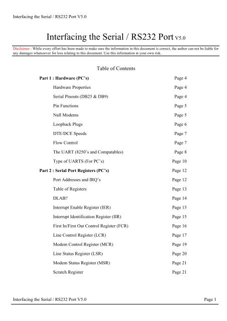
Interfacing the Serial/RS-232 Port
Interfacing the Serial/RS-232 Port
Interfacing the Serial/RS-232 Port

Create successful ePaper yourself
Turn your PDF publications into a flip-book with our unique Google optimized e-Paper software.
<strong>Interfacing</strong> <strong>the</strong> <strong>Serial</strong> / <strong>RS</strong><strong>232</strong> <strong>Port</strong> V5.0<br />
<strong>Interfacing</strong> <strong>the</strong> <strong>Serial</strong> / <strong>RS</strong><strong>232</strong> <strong>Port</strong> V5.0<br />
Disclaimer : While every effort has been made to make sure <strong>the</strong> information in this document is correct, <strong>the</strong> author can not be liable for<br />
any damages whatsoever for loss relating to this document. Use this information at your own risk.<br />
Table of Contents<br />
Part 1 : Hardware (PC’s) Page 4<br />
Hardware Properties Page 4<br />
<strong>Serial</strong> Pinouts (DB25 & DB9) Page 4<br />
Pin Functions Page 5<br />
Null Modems Page 5<br />
Loopback Plugs Page 6<br />
DTE/DCE Speeds Page 7<br />
Flow Control Page 7<br />
The UART (8250’s and Compatables) Page 8<br />
Type of UARTS (For PC’s) Page 10<br />
Part 2 : <strong>Serial</strong> <strong>Port</strong> Registers (PC’s) Page 12<br />
<strong>Port</strong> Addresses and IRQ’s Page 12<br />
Table of Registers Page 13<br />
DLAB Page 14<br />
Interrupt Enable Register (IER) Page 15<br />
Interrupt Identification Register (IIR) Page 15<br />
First In/First Out Control Register (FCR) Page 16<br />
Line Control Register (LCR) Page 17<br />
Modem Control Register (MCR) Page 19<br />
Line Status Register (LSR) Page 20<br />
Modem Status Register (MSR) Page 21<br />
Scratch Register Page 21<br />
<strong>Interfacing</strong> <strong>the</strong> <strong>Serial</strong> / <strong>RS</strong><strong>232</strong> <strong>Port</strong> V5.0 Page 1
<strong>Interfacing</strong> <strong>the</strong> <strong>Serial</strong> / <strong>RS</strong><strong>232</strong> <strong>Port</strong> V5.0<br />
Part 3 : Programming (PC’s) Page 22<br />
Polling or Interrupt Driven Page 22<br />
Termpoll.c - A Simple Comms Program using Polling Page 22<br />
Buff1024.c - An Interrupt Driven Comms Program Page 24<br />
Interrupt Vectors Page 27<br />
Interrupt Service Routine Page 28<br />
UART Configuartion Page 30<br />
Main Routine (Loop) Page 31<br />
Determining <strong>the</strong> type of UART via Software Page 31<br />
Part 4 : External Hardware - <strong>Interfacing</strong> Methods Page 33<br />
<strong>RS</strong>-<strong>232</strong> Waveforms Page 33<br />
<strong>RS</strong>-<strong>232</strong> Level Converters Page 34<br />
Making use of <strong>the</strong> serial format Page 34<br />
8250 and compatable UARTS Page 35<br />
CDP6402, AY-5-1015 / D36402R-9 etc UARTS Page 36<br />
Microcontrollers Page 39<br />
<strong>Interfacing</strong> <strong>the</strong> <strong>Serial</strong> / <strong>RS</strong><strong>232</strong> <strong>Port</strong> V5.0 Page 2
<strong>Interfacing</strong> <strong>the</strong> <strong>Serial</strong> / <strong>RS</strong><strong>232</strong> <strong>Port</strong> V5.0<br />
Introduction<br />
The <strong>Serial</strong> <strong>Port</strong> is harder to interface than <strong>the</strong> Parallel <strong>Port</strong>. In most cases, any device you connect<br />
to <strong>the</strong> serial port will need <strong>the</strong> serial transmission converted back to parallel so that it can be used. This<br />
can be done using a UART. On <strong>the</strong> software side of things, <strong>the</strong>re are many more registers that you have<br />
to attend to than on a Standard Parallel <strong>Port</strong>. (SPP)<br />
So what are <strong>the</strong> advantages of using serial data transfer ra<strong>the</strong>r than parallel<br />
1. <strong>Serial</strong> Cables can be longer than Parallel cables. The serial port transmits a '1'<br />
as -3 to -25 volts and a '0' as +3 to +25 volts where as a parallel port<br />
transmits a '0' as 0v and a '1' as 5v. Therefore <strong>the</strong> serial port can have a<br />
maximum swing of 50V compared to <strong>the</strong> parallel port which has a maximum<br />
swing of 5 Volts. Therefore cable loss is not going to be as much of a<br />
problem for serial cables than <strong>the</strong>y are for parallel.<br />
2. You don't need as many wires than parallel transmission. If your device<br />
needs to be mounted a far distance away from <strong>the</strong> computer <strong>the</strong>n 3 core cable<br />
(Null Modem Configuration) is going to be a lot cheaper that running 19 or<br />
25 core cable. However you must take into account <strong>the</strong> cost of <strong>the</strong> interfacing<br />
at each end.<br />
3. Infra Red devices have proven quite popular recently. You may of seen many<br />
electronic diaries and palmtop computers which have infra red capabilities<br />
build in. However could you imagine transmitting 8 bits of data at <strong>the</strong> one<br />
time across <strong>the</strong> room and being able to (from <strong>the</strong> devices point of view)<br />
decipher which bits are which Therefore serial transmission is used where<br />
one bit is sent at a time. IrDA-1 (The first infra red specifications) was<br />
capable of 115.2k baud and was interfaced into a UART. The pulse length<br />
however was cut down to 3/16th of a <strong>RS</strong><strong>232</strong> bit length to conserve power<br />
considering <strong>the</strong>se devices are mainly used on diaries, laptops and palmtops.<br />
4. Microcontroller's have also proven to be quite popular recently. Many of<br />
<strong>the</strong>se have in built SCI (<strong>Serial</strong> Communications Interfaces) which can be<br />
used to talk to <strong>the</strong> outside world. <strong>Serial</strong> Communication reduces <strong>the</strong> pin<br />
count of <strong>the</strong>se MPU's. Only two pins are commonly used, Transmit Data<br />
(TXD) and Receive Data (RXD) compared with at least 8 pins if you use a 8<br />
bit Parallel method (You may also require a Strobe).<br />
<strong>Interfacing</strong> <strong>the</strong> <strong>Serial</strong> / <strong>RS</strong><strong>232</strong> <strong>Port</strong> V5.0 Page 3
<strong>Interfacing</strong> <strong>the</strong> <strong>Serial</strong> / <strong>RS</strong><strong>232</strong> <strong>Port</strong> V5.0<br />
Part One : Hardware (PC's)<br />
Hardware Properties<br />
Devices which use serial cables for <strong>the</strong>ir communication are split into two categories. These are<br />
DCE (Data Communications Equipment) and DTE (Data Terminal Equipment.) Data Communications<br />
Equipment are devices such as your modem, TA adapter, plotter etc while Data Terminal Equipment is<br />
your Computer or Terminal.<br />
The electrical specifications of <strong>the</strong> serial port is contained in <strong>the</strong> EIA (Electronics Industry<br />
Association) <strong>RS</strong><strong>232</strong>C standard. It states many parameters such as -<br />
1. A "Space" (logic 0) will be between +3 and +25 Volts.<br />
2. A "Mark" (Logic 1) will be between -3 and -25 Volts.<br />
3. The region between +3 and -3 volts is undefined.<br />
4. An open circuit voltage should never exceed 25 volts. (In Reference to<br />
GND)<br />
5. A short circuit current should not exceed 500mA. The driver should be<br />
able to handle this without damage. (Take note of this one!)<br />
Above is no where near a complete list of <strong>the</strong> EIA standard. Line Capacitance, Maximum Baud<br />
Rates etc are also included. For more information please consult <strong>the</strong> EIA <strong>RS</strong><strong>232</strong>-E standard. It is<br />
interesting to note however, that <strong>the</strong> <strong>RS</strong><strong>232</strong>C standard specifies a maximum baud rate of 20,000 BPS!,<br />
which is ra<strong>the</strong>r slow by today's standards. Revised standards, EIA-<strong>232</strong>D & EIA-<strong>232</strong>E were released, in<br />
1987 & 1991 respectively.<br />
<strong>Serial</strong> <strong>Port</strong>s come in two "sizes", There are <strong>the</strong> D-Type 25 pin connector and <strong>the</strong> D-Type 9 pin<br />
connector both of which are male on <strong>the</strong> back of <strong>the</strong> PC, thus you will require a female connector on<br />
your device. Below is a table of pin connections for <strong>the</strong> 9 pin and 25 pin D-Type connectors.<br />
<strong>Serial</strong> Pinouts (D25 and D9 Connectors)<br />
D-Type-25 Pin<br />
No.<br />
D-Type-9 Pin No. Abbreviation<br />
Full Name<br />
Pin 2 Pin 3 TD Transmit Data<br />
Pin 3 Pin 2 RD Receive Data<br />
Pin 4 Pin 7 RTS Request To Send<br />
Pin 5 Pin 8 CTS Clear To Send<br />
<strong>Interfacing</strong> <strong>the</strong> <strong>Serial</strong> / <strong>RS</strong><strong>232</strong> <strong>Port</strong> V5.0 Page 4
<strong>Interfacing</strong> <strong>the</strong> <strong>Serial</strong> / <strong>RS</strong><strong>232</strong> <strong>Port</strong> V5.0<br />
Pin Functions<br />
Pin 6 Pin 6 DSR Data Set Ready<br />
Pin 7 Pin 5 SG Signal Ground<br />
Pin 8 Pin 1 CD Carrier Detect<br />
Pin 20 Pin 4 DTR Data Terminal Ready<br />
Pin 22 Pin 9 RI Ring Indicator<br />
Table 1 : D Type 9 Pin and D Type 25 Pin Connectors<br />
Abbreviation Full Name Function<br />
TD Transmit Data <strong>Serial</strong> Data Output (TXD)<br />
RD Receive Data <strong>Serial</strong> Data Input (RXD)<br />
CTS Clear to Send This line indicates that <strong>the</strong> Modem is ready to exchange<br />
data.<br />
DCD<br />
Data Carrier<br />
Detect<br />
When <strong>the</strong> modem detects a "Carrier" from <strong>the</strong> modem at<br />
<strong>the</strong> o<strong>the</strong>r end of <strong>the</strong> phone line, this Line becomes active.<br />
DSR Data Set Ready This tells <strong>the</strong> UART that <strong>the</strong> modem is ready to establish a<br />
link.<br />
DTR<br />
Data Terminal<br />
Ready<br />
This is <strong>the</strong> opposite to DSR. This tells <strong>the</strong> Modem that <strong>the</strong><br />
UART is ready to link.<br />
RTS Request To Send This line informs <strong>the</strong> Modem that <strong>the</strong> UART is ready to<br />
exchange data.<br />
RI Ring Indicator Goes active when modem detects a ringing signal from <strong>the</strong><br />
PSTN.<br />
Null Modems<br />
A Null Modem is used to connect two DTE's toge<strong>the</strong>r. This is commonly used as a cheap way to<br />
network games or to transfer files between computers using Zmodem Protocol, Xmodem Protocol etc.<br />
This can also be used with many Microprocessor Development Systems.<br />
<strong>Interfacing</strong> <strong>the</strong> <strong>Serial</strong> / <strong>RS</strong><strong>232</strong> <strong>Port</strong> V5.0 Page 5
<strong>Interfacing</strong> <strong>the</strong> <strong>Serial</strong> / <strong>RS</strong><strong>232</strong> <strong>Port</strong> V5.0<br />
Figure 1 : Null Modem Wiring Diagram<br />
Above is my preferred method of wiring a Null Modem. It only requires 3 wires (TD, RD & SG)<br />
to be wired straight through thus is more cost effective to use with long cable runs. The <strong>the</strong>ory of<br />
operation is reasonably easy. The aim is to make to computer think it is talking to a modem ra<strong>the</strong>r than<br />
ano<strong>the</strong>r computer. Any data transmitted from <strong>the</strong> first computer must be received by <strong>the</strong> second thus TD<br />
is connected to RD. The second computer must have <strong>the</strong> same set-up thus RD is connected to TD. Signal<br />
Ground (SG) must also be connected so both grounds are common to each computer.<br />
The Data Terminal Ready is looped back to Data Set Ready and Carrier Detect on both<br />
computers. When <strong>the</strong> Data Terminal Ready is asserted active, <strong>the</strong>n <strong>the</strong> Data Set Ready and Carrier<br />
Detect immediately become active. At this point <strong>the</strong> computer thinks <strong>the</strong> Virtual Modem to which it is<br />
connected is ready and has detected <strong>the</strong> carrier of <strong>the</strong> o<strong>the</strong>r modem.<br />
All left to worry about now is <strong>the</strong> Request to Send and Clear To Send. As both computers<br />
communicate toge<strong>the</strong>r at <strong>the</strong> same speed, flow control is not needed thus <strong>the</strong>se two lines are also linked<br />
toge<strong>the</strong>r on each computer. When <strong>the</strong> computer wishes to send data, it asserts <strong>the</strong> Request to Send high<br />
and as it's hooked toge<strong>the</strong>r with <strong>the</strong> Clear to Send, It immediately gets a reply that it is ok to send and<br />
does so.<br />
Notice that <strong>the</strong> ring indicator is not connected to anything of each end. This line is only used to<br />
tell <strong>the</strong> computer that <strong>the</strong>re is a ringing signal on <strong>the</strong> phone line. As we don't have a modem connected to<br />
<strong>the</strong> phone line this is left disconnected.<br />
LoopBack Plug<br />
This loopback plug can come in extremely handy when writing<br />
<strong>Serial</strong> / <strong>RS</strong><strong>232</strong> Communications Programs. It has <strong>the</strong> receive and<br />
transmit lines connected toge<strong>the</strong>r, so that anything transmitted out of<br />
<strong>the</strong> <strong>Serial</strong> <strong>Port</strong> is immediately received by <strong>the</strong> same port. If you<br />
connect this to a <strong>Serial</strong> <strong>Port</strong> an load a Terminal Program, anything<br />
you type will be immediately displayed on <strong>the</strong> screen. This can be<br />
used with <strong>the</strong> examples later in this tutorial.<br />
Figure 2 : Loopback Plug Wiring<br />
Diagram<br />
Please note that this is not intended for use with Diagnostic<br />
Programs and thus will probably not work. For <strong>the</strong>se programs you<br />
require a differently wired Loop Back plug which may vary from<br />
program to program.<br />
<strong>Interfacing</strong> <strong>the</strong> <strong>Serial</strong> / <strong>RS</strong><strong>232</strong> <strong>Port</strong> V5.0 Page 6
<strong>Interfacing</strong> <strong>the</strong> <strong>Serial</strong> / <strong>RS</strong><strong>232</strong> <strong>Port</strong> V5.0<br />
DTE / DCE Speeds<br />
We have already talked briefly about DTE & DCE. A typical Data Terminal Device is a<br />
computer and a typical Data Communications Device is a Modem. Often people will talk about DTE to<br />
DCE or DCE to DCE speeds. DTE to DCE is <strong>the</strong> speed between your modem and computer, sometimes<br />
referred to as your terminal speed. This should run at faster speeds than <strong>the</strong> DCE to DCE speed. DCE to<br />
DCE is <strong>the</strong> link between modems, sometimes called <strong>the</strong> line speed.<br />
Most people today will have 28.8K or 33.6K modems. Therefore we should expect <strong>the</strong> DCE to<br />
DCE speed to be ei<strong>the</strong>r 28.8K or 33.6K. Considering <strong>the</strong> high speed of <strong>the</strong> modem we should expect <strong>the</strong><br />
DTE to DCE speed to be about 115,200 BPS.(Maximum Speed of <strong>the</strong> 16550a UART) This is where<br />
some people often fall into a trap. The communications program which <strong>the</strong>y use have settings for DCE<br />
to DTE speeds. However <strong>the</strong>y see 9.6 KBPS, 14.4 KBPS etc and think it is your modem speed.<br />
Today's Modems should have Data Compression build into <strong>the</strong>m. This is very much like PK-ZIP<br />
but <strong>the</strong> software in your modem compresses and decompresses <strong>the</strong> data. When set up correctly you can<br />
expect compression ratios of 1:4 or even higher. 1 to 4 compression would be typical of a text file. If we<br />
were transferring that text file at 28.8K (DCE-DCE), <strong>the</strong>n when <strong>the</strong> modem compresses it you are<br />
actually transferring 115.2 KBPS between computers and thus have a DCE-DTE speed of 115.2 KBPS.<br />
Thus this is why <strong>the</strong> DCE-DTE should be much higher than your modem's connection speed.<br />
Some modem manufacturers quote a maximum compression ratio as 1:8. Lets say for example its<br />
on a new 33.6 KBPS modem <strong>the</strong>n we may get a maximum 268,800 BPS transfer between modem and<br />
UART. If you only have a 16550a which can do 115,200 BPS tops, <strong>the</strong>n you would be missing out on a<br />
extra bit of performance. Buying a 16C650 should fix your problem with a maximum transfer rate of<br />
230,400 BPS.<br />
However don't abuse your modem if you don't get <strong>the</strong>se rates. These are MAXIMUM<br />
compression ratios. In some instances if you try to send a already compressed file, your modem can<br />
spend more time trying <strong>the</strong> compress it, thus you get a transmission speed less than your modem's<br />
connection speed. If this occurs try turning off your data compression. This should be fixed on newer<br />
modems. Some files compress easier than o<strong>the</strong>rs thus any file which compresses easier is naturally going<br />
to have a higher compression ratio.<br />
Flow Control<br />
So if our DTE to DCE speed is several times faster than our DCE to DCE speed <strong>the</strong> PC can send<br />
data to your modem at 115,200 BPS. Sooner or later data is going to get lost as buffers overflow, thus<br />
flow control is used. Flow control has two basic varieties, Hardware or Software.<br />
Software flow control, sometimes expressed as Xon/Xoff uses two characters Xon and Xoff. Xon<br />
is normally indicated by <strong>the</strong> ASCII 17 character where as <strong>the</strong> ASCII 19 character is used for Xoff. The<br />
modem will only have a small buffer so when <strong>the</strong> computer fills it up <strong>the</strong> modem sends a Xoff character<br />
to tell <strong>the</strong> computer to stop sending data. Once <strong>the</strong> modem has room for more data it <strong>the</strong>n sends a Xon<br />
character and <strong>the</strong> computer sends more data. This type of flow control has <strong>the</strong> advantage that it doesn't<br />
require any more wires as <strong>the</strong> characters are sent via <strong>the</strong> TD/RD lines. However on slow links each<br />
character requires 10 bits which can slow communications down.<br />
Hardware flow control is also known as RTS/CTS flow control. It uses two wires in your serial<br />
cable ra<strong>the</strong>r than extra characters transmitted in your data lines. Thus hardware flow control will not<br />
<strong>Interfacing</strong> <strong>the</strong> <strong>Serial</strong> / <strong>RS</strong><strong>232</strong> <strong>Port</strong> V5.0 Page 7
<strong>Interfacing</strong> <strong>the</strong> <strong>Serial</strong> / <strong>RS</strong><strong>232</strong> <strong>Port</strong> V5.0<br />
slow down transmission times like Xon-Xoff does. When <strong>the</strong> computer wishes to send data it takes<br />
active <strong>the</strong> Request to Send line. If <strong>the</strong> modem has room for this data, <strong>the</strong>n <strong>the</strong> modem will reply by<br />
taking active <strong>the</strong> Clear to Send line and <strong>the</strong> computer starts sending data. If <strong>the</strong> modem does not have <strong>the</strong><br />
room <strong>the</strong>n it will not send a Clear to Send.<br />
The UART (8250 and Compatibles)<br />
UART stands for Universal Asynchronous Receiver / Transmitter. Its <strong>the</strong> little box of tricks<br />
found on your serial card which plays <strong>the</strong> little games with your modem or o<strong>the</strong>r connected devices.<br />
Most cards will have <strong>the</strong> UART's integrated into o<strong>the</strong>r chips which may also control your parallel port,<br />
games port, floppy or hard disk drives and are typically surface mount devices. The 8250 series, which<br />
includes <strong>the</strong> 16450, 16550, 16650, & 16750 UARTS are <strong>the</strong> most commonly found type in your PC.<br />
Later we will look at o<strong>the</strong>r types which can be used in your homemade devices and projects.<br />
Figure 3 : Pin Diagrams for 16550, 16450 & 8250 UARTs<br />
The 16550 is chip compatible with <strong>the</strong> 8250 & 16450. The only two differences are pins 24 &<br />
29. On <strong>the</strong> 8250 Pin 24 was chip select out which functioned only as a indicator to if <strong>the</strong> chip was active<br />
or not. Pin 29 was not connected on <strong>the</strong> 8250/16450 UARTs. The 16550 introduced two new pins in<br />
<strong>the</strong>ir place. These are Transmit Ready and Receive Ready which can be implemented with DMA (Direct<br />
Memory Access). These Pins have two different modes of operation. Mode 0 supports single transfer<br />
DMA where as Mode 1 supports Multi-transfer DMA.<br />
Mode 0 is also called <strong>the</strong> 16450 mode. This mode is selected when <strong>the</strong> FIFO buffers are disabled<br />
via Bit 0 of <strong>the</strong> FIFO Control Register or When <strong>the</strong> FIFO buffers are enabled but DMA Mode Select = 0.<br />
(Bit 3 of FCR) In this mode RXRDY is active low when at least one character (Byte) is present in <strong>the</strong><br />
Receiver Buffer. RXRDY will go inactive high when no more characters are left in <strong>the</strong> Receiver Buffer.<br />
TXRDY will be active low when <strong>the</strong>re are no characters in <strong>the</strong> Transmit Buffer. It will go inactive high<br />
after <strong>the</strong> first character / byte is loaded into <strong>the</strong> Transmit Buffer.<br />
Mode 1 is when <strong>the</strong> FIFO buffers are active and <strong>the</strong> DMA Mode Select = 1. In Mode 1, RXRDY<br />
will go active low when <strong>the</strong> trigger level is reached or when 16550 Time Out occurs and will return to<br />
inactive state when no more characters are left in <strong>the</strong> FIFO. TXRDY will be active when no characters<br />
are present in <strong>the</strong> Transmit Buffer and will go inactive when <strong>the</strong> FIFO Transmit Buffer is completely<br />
Full.<br />
<strong>Interfacing</strong> <strong>the</strong> <strong>Serial</strong> / <strong>RS</strong><strong>232</strong> <strong>Port</strong> V5.0 Page 8
<strong>Interfacing</strong> <strong>the</strong> <strong>Serial</strong> / <strong>RS</strong><strong>232</strong> <strong>Port</strong> V5.0<br />
All <strong>the</strong> UARTs pins are TTL compatible. That includes TD, RD, RI, DCD, DSR, CTS, DTR and<br />
RTS which all interface into your serial plug, typically a D-type connector. Therefore <strong>RS</strong><strong>232</strong> Level<br />
Converters (which we talk about in detail later) are used. These are commonly <strong>the</strong> DS1489 Receiver and<br />
<strong>the</strong> DS1488 as <strong>the</strong> PC has +12 and -12 volt rails which can be used by <strong>the</strong>se devices. The <strong>RS</strong><strong>232</strong><br />
Converters will convert <strong>the</strong> TTL signal into <strong>RS</strong><strong>232</strong> Logic Levels.<br />
Pin No. Name Notes<br />
Pin 1:8 D0:D7 Data Bus<br />
Pin 9 RCLK Receiver Clock Input. The frequency of this input should equal <strong>the</strong><br />
receivers baud rate * 16<br />
Pin 10 RD Receive Data<br />
Pin 11 TD Transmit Data<br />
Pin 12 CS0 Chip Select 0 - Active High<br />
Pin 13 CS1 Chip Select 1 - Active High<br />
Pin 14 nCS2 Chip Select 2 - Active Low<br />
Pin 15 nBAUDOUT Baud Output - Output from Programmable Baud Rate Generator.<br />
Frequency = (Baud Rate x 16)<br />
Pin 16 XIN External Crystal Input - Used for Baud Rate Generator Oscillator<br />
Pin 17 XOUT External Crystal Output<br />
Pin 18 nWR Write Line - Inverted<br />
Pin 19 WR Write Line - Not Inverted<br />
Pin 20 VSS Connected to Common Ground<br />
Pin 21 RD Read Line - Inverted<br />
Pin 22 nRD Read Line - Not Inverted<br />
Pin 23 DDIS Driver Disable. This pin goes low when CPU is reading from UART.<br />
Can be connected to Bus Transceiver in case of high capacity data<br />
bus.<br />
Pin 24 nTXRDY Transmit Ready<br />
Pin 25 nADS Address Strobe. Used if signals are not stable during read or write<br />
cycle<br />
Pin 26 A2 Address Bit 2<br />
Pin 27 A1 Address Bit 1<br />
Pin 28 A0 Address Bit 0<br />
<strong>Interfacing</strong> <strong>the</strong> <strong>Serial</strong> / <strong>RS</strong><strong>232</strong> <strong>Port</strong> V5.0 Page 9
<strong>Interfacing</strong> <strong>the</strong> <strong>Serial</strong> / <strong>RS</strong><strong>232</strong> <strong>Port</strong> V5.0<br />
Pin 29 nRXRDY Receive Ready<br />
Pin 30 INTR Interrupt Output<br />
Pin 31 nOUT2 User Output 2<br />
Pin 32 nRTS Request to Send<br />
Pin 33 nDTR Data Terminal Ready<br />
Pin 34 nOUT1 User Output 1<br />
Pin 35 MR Master Reset<br />
Pin 36 nCTS Clear To Send<br />
Pin 37 nDSR Data Set Ready<br />
Pin 38 nDCD Data Carrier Detect<br />
Pin 39 nRI Ring Indicator<br />
Pin 40 VDD + 5 Volts<br />
Table 2 : Pin Assignments for 16550A UART<br />
The UART requires a Clock to run. If you look at your serial card a common crystal found is<br />
ei<strong>the</strong>r a 1.8432 MHZ or a 18.432 MHZ Crystal. The crystal in connected to <strong>the</strong> XIN-XOUT pins of <strong>the</strong><br />
UART using a few extra components which help <strong>the</strong> crystal to start oscillating. This clock will be used<br />
for <strong>the</strong> Programmable Baud Rate Generator which directly interfaces into <strong>the</strong> transmit timing circuits but<br />
not directly into <strong>the</strong> receiver timing circuits. For this an external connection mast be made from pin 15<br />
(BaudOut) to pin 9 (Receiver clock in.) Note that <strong>the</strong> clock signal will be at Baudrate * 16.<br />
If you are serious about pursuing <strong>the</strong> 16550 UART used in your PC fur<strong>the</strong>r, <strong>the</strong>n would suggest<br />
downloading a copy of <strong>the</strong> PC16550D data sheet from National Semiconductor,<br />
(http://www.natsemi.com) Data sheets are available in .PDF format so you will need Adobe Acrobat<br />
Reader to read <strong>the</strong>se. Texas Instruments (http://www.ti.com) has released <strong>the</strong> 16750 UART which has 64<br />
Byte FIFO's. Data Sheets for <strong>the</strong> TL16C750 are available from <strong>the</strong> Texas Instruments Site.<br />
Types of UARTS (For PC's)<br />
8250 First UART in this series. It contains no scratch register. The 8250A was an<br />
improved version of <strong>the</strong> 8250 which operates faster on <strong>the</strong> bus side.<br />
8250A<br />
8250B<br />
This UART is faster than <strong>the</strong> 8250 on <strong>the</strong> bus side. Looks exactly <strong>the</strong> same to<br />
software than 16450.<br />
Very similar to that of <strong>the</strong> 8250 UART.<br />
16450 Used in AT's (Improved bus speed over 8250's). Operates comfortably at<br />
38.4KBPS. Still quite common today.<br />
<strong>Interfacing</strong> <strong>the</strong> <strong>Serial</strong> / <strong>RS</strong><strong>232</strong> <strong>Port</strong> V5.0 Page 10
<strong>Interfacing</strong> <strong>the</strong> <strong>Serial</strong> / <strong>RS</strong><strong>232</strong> <strong>Port</strong> V5.0<br />
16550 This was <strong>the</strong> first generation of buffered UART. It has a 16 byte buffer, however it<br />
doesn't work and is replaced with <strong>the</strong> 16550A.<br />
16550A<br />
Is <strong>the</strong> most common UART use for high speed communications eg 14.4K &<br />
28.8K Modems. They made sure <strong>the</strong> FIFO buffers worked on this UART.<br />
16650 Very recent breed of UART. Contains a 32 byte FIFO, Programmable X-On / X-<br />
Off characters and supports power management.<br />
16750 Produced by Texas Instruments. Contains a 64 byte FIFO.<br />
<strong>Interfacing</strong> <strong>the</strong> <strong>Serial</strong> / <strong>RS</strong><strong>232</strong> <strong>Port</strong> V5.0 Page 11
<strong>Interfacing</strong> <strong>the</strong> <strong>Serial</strong> / <strong>RS</strong><strong>232</strong> <strong>Port</strong> V5.0<br />
Part Two : <strong>Serial</strong> <strong>Port</strong>'s Registers (PC's)<br />
<strong>Port</strong> Addresses & IRQ's<br />
Name Address IRQ<br />
COM 1 3F8 4<br />
COM 2 2F8 3<br />
COM 3 3E8 4<br />
COM 4 2E8 3<br />
Table 3 : Standard <strong>Port</strong> Addresses<br />
Above is <strong>the</strong> standard port addresses. These should work for most P.C's. If you just happen to be<br />
lucky enough to own a IBM P/S2 which has a micro-channel bus, <strong>the</strong>n expect a different set of addresses<br />
and IRQ's. Just like <strong>the</strong> LPT ports, <strong>the</strong> base addresses for <strong>the</strong> COM ports can be read from <strong>the</strong> BIOS<br />
Data Area.<br />
Start Address<br />
Function<br />
0000:0400 COM1's Base Address<br />
0000:0402 COM2's Base Address<br />
0000:0404 COM3's Base Address<br />
0000:0406 COM4's Base Address<br />
Table 4 - COM <strong>Port</strong> Addresses in <strong>the</strong> BIOS Data Area;<br />
The above table shows <strong>the</strong> address at which we can find <strong>the</strong> Communications (COM) ports<br />
addresses in <strong>the</strong> BIOS Data Area. Each address will take up 2 bytes. The following sample program in C,<br />
shows how you can read <strong>the</strong>se locations to obtain <strong>the</strong> addresses of your communications ports.<br />
<strong>Interfacing</strong> <strong>the</strong> <strong>Serial</strong> / <strong>RS</strong><strong>232</strong> <strong>Port</strong> V5.0 Page 12
<strong>Interfacing</strong> <strong>the</strong> <strong>Serial</strong> / <strong>RS</strong><strong>232</strong> <strong>Port</strong> V5.0<br />
#include <br />
#include <br />
void main(void)<br />
{<br />
unsigned int far *ptraddr; /* Pointer to location of <strong>Port</strong> Addresses */<br />
unsigned int address; /* Address of <strong>Port</strong> */<br />
int a;<br />
ptraddr=(unsigned int far *)0x00000400;<br />
for (a = 0; a < 4; a++)<br />
{<br />
address = *ptraddr;<br />
if (address == 0)<br />
printf("No port found for COM%d \n",a+1);<br />
else<br />
printf("Address assigned to COM%d is %Xh\n",a+1,address);<br />
*ptraddr++;<br />
}<br />
}<br />
Table of Registers<br />
Base Address DLAB Read/Write Abr.<br />
Register Name<br />
+ 0 =0 Write - Transmitter Holding Buffer<br />
=0 Read - Receiver Buffer<br />
=1 Read/Write - Divisor Latch Low Byte<br />
+ 1 =0 Read/Write IER Interrupt Enable Register<br />
=1 Read/Write - Divisor Latch High Byte<br />
+ 2 - Read IIR Interrupt Identification Register<br />
- Write FCR FIFO Control Register<br />
+ 3 - Read/Write LCR Line Control Register<br />
+ 4 - Read/Write MCR Modem Control Register<br />
+ 5 - Read LSR Line Status Register<br />
+ 6 - Read MSR Modem Status Register<br />
+ 7 - Read/Write - Scratch Register<br />
Table 5 : Table of Registers<br />
<strong>Interfacing</strong> <strong>the</strong> <strong>Serial</strong> / <strong>RS</strong><strong>232</strong> <strong>Port</strong> V5.0 Page 13
<strong>Interfacing</strong> <strong>the</strong> <strong>Serial</strong> / <strong>RS</strong><strong>232</strong> <strong>Port</strong> V5.0<br />
DLAB <br />
You will have noticed in <strong>the</strong> table of registers that <strong>the</strong>re is a DLAB column. When DLAB is set<br />
to '0' or '1' some of <strong>the</strong> registers change. This is how <strong>the</strong> UART is able to have 12 registers (including <strong>the</strong><br />
scratch register) through only 8 port addresses. DLAB stands for Divisor Latch Access Bit. When DLAB<br />
is set to '1' via <strong>the</strong> line control register, two registers become available from which you can set your<br />
speed of communications measured in bits per second.<br />
The UART will have a crystal which should oscillate around 1.8432 MHZ. The UART<br />
incorporates a divide by 16 counter which simply divides <strong>the</strong> incoming clock signal by 16. Assuming we<br />
had <strong>the</strong> 1.8432 MHZ clock signal, that would leave us with a maximum, 115,200 hertz signal making<br />
<strong>the</strong> UART capable of transmitting and receiving at 115,200 Bits Per Second (BPS). That would be<br />
fine for some of <strong>the</strong> faster modems and devices which can handle that speed, but o<strong>the</strong>rs just wouldn't<br />
communicate at all. Therefore <strong>the</strong> UART is fitted with a Programmable Baud Rate Generator which is<br />
controlled by two registers.<br />
Lets say for example we only wanted to communicate at 2400 BPS. We worked out that we<br />
would have to divide 115,200 by 48 to get a workable 2400 Hertz Clock. The "Divisor", in this case 48,<br />
is stored in <strong>the</strong> two registers controlled by <strong>the</strong> "Divisor Latch Access Bit". This divisor can be any<br />
number which can be stored in 16 bits (ie 0 to 65535). The UART only has a 8 bit data bus, thus this is<br />
where <strong>the</strong> two registers are used. The first register (Base + 0) when DLAB = 1 stores <strong>the</strong> "Divisor latch<br />
low byte" where as <strong>the</strong> second register (base + 1 when DLAB = 1) stores <strong>the</strong> "Divisor latch high byte."<br />
Below is a table of some more common speeds and <strong>the</strong>ir divisor latch high bytes & low bytes.<br />
Note that all <strong>the</strong> divisors are shown in Hexadecimal.<br />
Speed (BPS) Divisor (Dec) Divisor Latch High Byte Divisor Latch Low Byte<br />
50 2304 09h 00h<br />
300 384 01h 80h<br />
600 192 00h C0h<br />
2400 48 00h 30h<br />
4800 24 00h 18h<br />
9600 12 00h 0Ch<br />
19200 6 00h 06h<br />
38400 3 00h 03h<br />
57600 2 00h 02h<br />
115200 1 00h 01h<br />
Table 6 : Table of Commonly Used Baudrate Divisors<br />
<strong>Interfacing</strong> <strong>the</strong> <strong>Serial</strong> / <strong>RS</strong><strong>232</strong> <strong>Port</strong> V5.0 Page 14
<strong>Interfacing</strong> <strong>the</strong> <strong>Serial</strong> / <strong>RS</strong><strong>232</strong> <strong>Port</strong> V5.0<br />
Interrupt Enable Register (IER)<br />
Bit<br />
Notes<br />
Bit 7<br />
Bit 6<br />
Reserved<br />
Reserved<br />
Bit 5 Enables Low Power Mode (16750)<br />
Bit 4 Enables Sleep Mode (16750)<br />
Bit 3<br />
Bit 2<br />
Bit 1<br />
Bit 0<br />
Enable Modem Status Interrupt<br />
Enable Receiver Line Status Interrupt<br />
Enable Transmitter Holding Register Empty Interrupt<br />
Enable Received Data Available Interrupt<br />
Table 7 : Interrupt Enable Register<br />
The Interrupt Enable Register could possibly be one of <strong>the</strong> easiest registers on a UART to<br />
understand. Setting Bit 0 high enables <strong>the</strong> Received Data Available Interrupt which generates an<br />
interrupt when <strong>the</strong> receiving register/FIFO contains data to be read by <strong>the</strong> CPU.<br />
Bit 1 enables Transmit Holding Register Empty Interrupt. This interrupts <strong>the</strong> CPU when <strong>the</strong><br />
transmitter buffer is empty. Bit 2 enables <strong>the</strong> receiver line status interrupt. The UART will interrupt<br />
when <strong>the</strong> receiver line status changes. Likewise for bit 3 which enables <strong>the</strong> modem status interrupt. Bits<br />
4 to 7 are <strong>the</strong> easy ones. They are simply reserved. (If only everything was that easy!)<br />
Interrupt Identification Register (IIR)<br />
Bit<br />
Notes<br />
Bits 6 : 7 Bit 6 Bit 7<br />
0 0 No FIFO<br />
0 1 FIFO Enabled but Unusable<br />
1 1 FIFO Enabled<br />
Bit 5 64 Byte Fifo Enabled (16750 only)<br />
Bit 4 Reserved<br />
<strong>Interfacing</strong> <strong>the</strong> <strong>Serial</strong> / <strong>RS</strong><strong>232</strong> <strong>Port</strong> V5.0 Page 15
<strong>Interfacing</strong> <strong>the</strong> <strong>Serial</strong> / <strong>RS</strong><strong>232</strong> <strong>Port</strong> V5.0<br />
Bit 3 0 Reserved on 8250, 16450<br />
Bits 1 : 2 Bit 2 Bit 1<br />
1 16550 Time-out Interrupt Pending<br />
0 0 Modem Status Interrupt<br />
0 1 Transmitter Holding Register Empty Interrupt<br />
1 0 Received Data Available Interrupt<br />
1 1 Receiver Line Status Interrupt<br />
Bit 0 0 Interrupt Pending<br />
1 No Interrupt Pending<br />
Table 8 : Interrupt Identification Register<br />
The interrupt identification register is a read only register. Bits 6 and 7 give status on <strong>the</strong> FIFO<br />
Buffer. When both bits are '0' no FIFO buffers are active. This should be <strong>the</strong> only result you will get<br />
from a 8250 or 16450. If bit 7 is active but bit 6 is not active <strong>the</strong>n <strong>the</strong> UART has it's buffers enabled but<br />
are unusable. This occurs on <strong>the</strong> 16550 UART where a bug in <strong>the</strong> FIFO buffer made <strong>the</strong> FIFO's<br />
unusable. If both bits are '1' <strong>the</strong>n <strong>the</strong> FIFO buffers are enabled and fully operational.<br />
Bits 4 and 5 are reserved. Bit 3 shows <strong>the</strong> status of <strong>the</strong> time-out interrupt on a 16550 or higher.<br />
Lets jump to Bit 0 which shows whe<strong>the</strong>r an interrupt has occurred. If an interrupt has occurred<br />
it's status will shown by bits 1 and 2. These interrupts work on a priority status. The Line Status Interrupt<br />
has <strong>the</strong> highest Priority, followed by <strong>the</strong> Data Available Interrupt, <strong>the</strong>n <strong>the</strong> Transmit Register Empty<br />
Interrupt and <strong>the</strong>n <strong>the</strong> Modem Status Interrupt which has <strong>the</strong> lowest priority.<br />
First In / First Out Control Register (FCR)<br />
Bit<br />
Notes<br />
Bits 6 : 7 Bit 7 Bit 6 Interrupt Trigger Level<br />
0 0 1 Byte<br />
0 1 4 Bytes<br />
1 0 8 Bytes<br />
1 1 14 Bytes<br />
Bit 5<br />
Bit 4<br />
Enable 64 Byte FIFO (16750 only)<br />
Reserved<br />
<strong>Interfacing</strong> <strong>the</strong> <strong>Serial</strong> / <strong>RS</strong><strong>232</strong> <strong>Port</strong> V5.0 Page 16
<strong>Interfacing</strong> <strong>the</strong> <strong>Serial</strong> / <strong>RS</strong><strong>232</strong> <strong>Port</strong> V5.0<br />
Bit 3<br />
Bit 2<br />
Bit 1<br />
Bit 0<br />
DMA Mode Select. Change status of RXRDY & TXRDY pins<br />
from mode 1 to mode 2.<br />
Clear Transmit FIFO<br />
Clear Receive FIFO<br />
Enable FIFO's<br />
Table 9 : FIFO Control Register<br />
The FIFO register is a write only register. This register is used to control <strong>the</strong> FIFO (First In / First<br />
Out) buffers which are found on 16550's and higher.<br />
Bit 0 enables <strong>the</strong> operation of <strong>the</strong> receive and transmit FIFO's. Writing a '0' to this bit will disable<br />
<strong>the</strong> operation of transmit and receive FIFO's, thus you will loose all data stored in <strong>the</strong>se FIFO buffers.<br />
Bit's 1 and 2 control <strong>the</strong> clearing of <strong>the</strong> transmit or receive FIFO's. Bit 1 is responsible for <strong>the</strong><br />
receive buffer while bit 2 is responsible for <strong>the</strong> transmit buffer. Setting <strong>the</strong>se bits to 1 will only clear <strong>the</strong><br />
contents of <strong>the</strong> FIFO and will not affect <strong>the</strong> shift registers. These two bits are self resetting, thus you<br />
don't need to set <strong>the</strong> bits to '0' when finished.<br />
Bit 3 enables <strong>the</strong> DMA mode select which is found on 16550 UARTs and higher. More on this<br />
later. Bits 4 and 5 are those easy type again, Reserved.<br />
Bits 6 and 7 are used to set <strong>the</strong> triggering level on <strong>the</strong> Receive FIFO. For example if bit 7 was set<br />
to '1' and bit 6 was set to '0' <strong>the</strong>n <strong>the</strong> trigger level is set to 8 bytes. When <strong>the</strong>re is 8 bytes of data in <strong>the</strong><br />
receive FIFO <strong>the</strong>n <strong>the</strong> Received Data Available interrupt is set. See (IIR)<br />
Line Control Register (LCR)<br />
Bit<br />
Notes<br />
Bit 7 1 Divisor Latch Access Bit<br />
0 Access to Receiver buffer, Transmitter buffer & Interrupt<br />
Enable Register<br />
Bit 6<br />
Set Break Enable<br />
Bits 3 : 5 Bit 5 Bit 4 Bit 3 Parity Select<br />
X X 0 No Parity<br />
0 0 1 Odd Parity<br />
0 1 1 Even Parity<br />
1 0 1 High Parity (Sticky)<br />
1 1 1 Low Parity (Sticky)<br />
<strong>Interfacing</strong> <strong>the</strong> <strong>Serial</strong> / <strong>RS</strong><strong>232</strong> <strong>Port</strong> V5.0 Page 17
<strong>Interfacing</strong> <strong>the</strong> <strong>Serial</strong> / <strong>RS</strong><strong>232</strong> <strong>Port</strong> V5.0<br />
Bit 2<br />
Length of Stop Bit<br />
0 One Stop Bit<br />
1 2 Stop bits for words of length 6,7 or 8 bits or 1.5 Stop<br />
Bits for Word lengths of 5 bits.<br />
Bits 0 : 1 Bit 1 Bit 0 Word Length<br />
0 0 5 Bits<br />
0 1 6 Bits<br />
1 0 7 Bits<br />
1 1 8 Bits<br />
Table 10 : Line Control Register<br />
The Line Control register sets <strong>the</strong> basic parameters for communication. Bit 7 is <strong>the</strong> Divisor Latch<br />
Access Bit or DLAB for short. We have already talked about what it does. (See DLAB) Bit 6 Sets break<br />
enable. When active, <strong>the</strong> TD line goes into "Spacing" state which causes a break in <strong>the</strong> receiving UART.<br />
Setting this bit to '0' Disables <strong>the</strong> Break.<br />
Bits 3,4 and 5 select parity. If you study <strong>the</strong> 3 bits, you will find that bit 3 controls parity. That is,<br />
if it is set to '0' <strong>the</strong>n no parity is used, but if it is set to '1' <strong>the</strong>n parity is used. Jumping to bit 5, we can see<br />
that it controls sticky parity. Sticky parity is simply when <strong>the</strong> parity bit is always transmitted and checked<br />
as a '1' or '0'. This has very little success in checking for errors as if <strong>the</strong> first 4 bits contain errors but <strong>the</strong><br />
sticky parity bit contains <strong>the</strong> appropriately set bit, <strong>the</strong>n a parity error will not result. Sticky high parity is<br />
<strong>the</strong> use of a '1' for <strong>the</strong> parity bit, while <strong>the</strong> opposite, sticky low parity is <strong>the</strong> use of a '0' for <strong>the</strong> parity bit.<br />
If bit 5 controls sticky parity, <strong>the</strong>n turning this bit off must produce normal parity provided bit 3<br />
is still set to '1'. Odd parity is when <strong>the</strong> parity bit is transmitted as a '1' or '0' so that <strong>the</strong>re is a odd number<br />
of 1's. Even parity must <strong>the</strong>n be <strong>the</strong> parity bit produces and even number of 1's. This provides better error<br />
checking but still is not perfect, thus CRC-32 is often used for software error correction. If one bit<br />
happens to be inverted with even or odd parity set, <strong>the</strong>n a parity error will occur, however if two bits are<br />
flipped in such a way that it produces <strong>the</strong> correct parity bit <strong>the</strong>n an parity error will no occur.<br />
Bit 2 sets <strong>the</strong> length of <strong>the</strong> stop bits. Setting this bit to '0' will produce one stop bit, however<br />
setting it to '1' will produce ei<strong>the</strong>r 1.5 or 2 stop bits depending upon <strong>the</strong> word length. Note that <strong>the</strong><br />
receiver only checks <strong>the</strong> first stop bit.<br />
Bits 0 and 1 set <strong>the</strong> word length. This should be pretty straight forward. A word length of 8 bits is<br />
most commonly used today.<br />
<strong>Interfacing</strong> <strong>the</strong> <strong>Serial</strong> / <strong>RS</strong><strong>232</strong> <strong>Port</strong> V5.0 Page 18
<strong>Interfacing</strong> <strong>the</strong> <strong>Serial</strong> / <strong>RS</strong><strong>232</strong> <strong>Port</strong> V5.0<br />
Modem Control Register (MCR)<br />
Bit<br />
Notes<br />
Bit 7<br />
Bit 6<br />
Bit 5<br />
Bit 4<br />
Reserved<br />
Reserved<br />
Autoflow Control Enabled (16750 only)<br />
LoopBack Mode<br />
Bit 3 Aux Output 2<br />
Bit 2 Aux Output 1<br />
Bit 1<br />
Bit 0<br />
Force Request to Send<br />
Force Data Terminal Ready<br />
Table 11 : Modem Control Register<br />
The Modem Control Register is a Read/Write Register. Bits 5,6 and 7 are reserved. Bit 4<br />
activates <strong>the</strong> loopback mode. In Loopback mode <strong>the</strong> transmitter serial output is placed into marking<br />
state. The receiver serial input is disconnected. The transmitter out is looped back to <strong>the</strong> receiver in.<br />
DSR, CTS, RI & DCD are disconnected. DTR, RTS, OUT1 & OUT2 are connected to <strong>the</strong> modem<br />
control inputs. The modem control output pins are <strong>the</strong>n place in an inactive state. In this mode any data<br />
which is placed in <strong>the</strong> transmitter registers for output is received by <strong>the</strong> receiver circuitry on <strong>the</strong> same<br />
chip and is available at <strong>the</strong> receiver buffer. This can be used to test <strong>the</strong> UARTs operation.<br />
Aux Output 2 maybe connected to external circuitry which controls <strong>the</strong> UART-CPU interrupt process.<br />
Aux Output 1 is normally disconnected, but on some cards is used to switch between a 1.8432MHZ crystal<br />
to a 4MHZ crystal which is used for MIDI. Bits 0 and 1 simply control <strong>the</strong>ir relevant data lines. For example<br />
setting bit 1 to '1' makes <strong>the</strong> request to send line active.<br />
<strong>Interfacing</strong> <strong>the</strong> <strong>Serial</strong> / <strong>RS</strong><strong>232</strong> <strong>Port</strong> V5.0 Page 19
<strong>Interfacing</strong> <strong>the</strong> <strong>Serial</strong> / <strong>RS</strong><strong>232</strong> <strong>Port</strong> V5.0<br />
Line Status Register (LSR)<br />
Bit<br />
Notes<br />
Bit 7<br />
Bit 6<br />
Bit 5<br />
Bit 4<br />
Bit 3<br />
Bit 2<br />
Bit 1<br />
Bit 0<br />
Error in Received FIFO<br />
Empty Data Holding Registers<br />
Empty Transmitter Holding Register<br />
Break Interrupt<br />
Framing Error<br />
Parity Error<br />
Overrun Error<br />
Data Ready<br />
Table 12 : Line Status Register<br />
The line status register is a read only register. Bit 7 is <strong>the</strong> error in received FIFO bit. This bit is<br />
high when at least one break, parity or framing error has occurred on a byte which is contained in <strong>the</strong><br />
FIFO.<br />
When bit 6 is set, both <strong>the</strong> transmitter holding register and <strong>the</strong> shift register are empty. The<br />
UART's holding register holds <strong>the</strong> next byte of data to be sent in parallel fashion. The shift register is<br />
used to convert <strong>the</strong> byte to serial, so that it can be transmitted over one line. When bit 5 is set, only <strong>the</strong><br />
transmitter holding register is empty. So what's <strong>the</strong> difference between <strong>the</strong> two When bit 6, <strong>the</strong><br />
transmitter holding and shift registers are empty, no serial conversions are taking place so <strong>the</strong>re should<br />
be no activity on <strong>the</strong> transmit data line. When bit 5 is set, <strong>the</strong> transmitter holding register is empty, thus<br />
ano<strong>the</strong>r byte can be sent to <strong>the</strong> data port, but a serial conversion using <strong>the</strong> shift register may be taking<br />
place.<br />
The break interrupt (Bit 4) occurs when <strong>the</strong> received data line is held in a logic state '0' (Space)<br />
for more than <strong>the</strong> time it takes to send a full word. That includes <strong>the</strong> time for <strong>the</strong> start bit, data bits, parity<br />
bits and stop bits.<br />
A framing error (Bit 3) occurs when <strong>the</strong> last bit is not a stop bit. This may occur due to a timing<br />
error. You will most commonly encounter a framing error when using a null modem linking two<br />
computers or a protocol analyzer when <strong>the</strong> speed at which <strong>the</strong> data is being sent is different to that of<br />
what you have <strong>the</strong> UART set to receive it at.<br />
A overrun error normally occurs when your program can't read from <strong>the</strong> port fast enough. If you<br />
don't get an incoming byte out of <strong>the</strong> register fast enough, and ano<strong>the</strong>r byte just happens to be received,<br />
<strong>the</strong>n <strong>the</strong> last byte will be lost and a overrun error will result.<br />
Bit 0 shows data ready, which means that a byte has been received by <strong>the</strong> UART and is at <strong>the</strong><br />
receiver buffer ready to be read.<br />
<strong>Interfacing</strong> <strong>the</strong> <strong>Serial</strong> / <strong>RS</strong><strong>232</strong> <strong>Port</strong> V5.0 Page 20
<strong>Interfacing</strong> <strong>the</strong> <strong>Serial</strong> / <strong>RS</strong><strong>232</strong> <strong>Port</strong> V5.0<br />
Modem Status Register (MSR)<br />
Bit<br />
Notes<br />
Bit 7<br />
Bit 6<br />
Bit 5<br />
Bit 4<br />
Bit 3<br />
Bit 2<br />
Bit 1<br />
Bit 0<br />
Carrier Detect<br />
Ring Indicator<br />
Data Set Ready<br />
Clear To Send<br />
Delta Data Carrier Detect<br />
Trailing Edge Ring Indicator<br />
Delta Data Set Ready<br />
Delta Clear to Send<br />
Table 13 : Modem Status Register<br />
Bit 0 of <strong>the</strong> modem status register shows delta clear to send, delta meaning a change in, thus<br />
delta clear to send means that <strong>the</strong>re was a change in <strong>the</strong> clear to send line, since <strong>the</strong> last read of this<br />
register. This is <strong>the</strong> same for bits 1 and 3. Bit 1 shows a change in <strong>the</strong> Data Set Ready line where as Bit 3<br />
shows a change in <strong>the</strong> Data Carrier Detect line. Bit 2 is <strong>the</strong> Trailing Edge Ring Indicator which indicates<br />
that <strong>the</strong>re was a transformation from low to high state on <strong>the</strong> Ring Indicator line.<br />
Bits 4 to 7 show <strong>the</strong> current state of <strong>the</strong> data lines when read. Bit 7 shows Carrier Detect, Bit 6<br />
shows Ring Indicator, Bit 5 shows Data Set Ready & Bit 4 shows <strong>the</strong> status of <strong>the</strong> Clear To Send line.<br />
Scratch Register<br />
The scratch register is not used for communications but ra<strong>the</strong>r used as a place to leave a byte of<br />
data. The only real use it has is to determine whe<strong>the</strong>r <strong>the</strong> UART is a 8250/8250B or a 8250A/16450 and<br />
even that is not very practical today as <strong>the</strong> 8250/8250B was never designed for AT's and can't hack <strong>the</strong><br />
bus speed.<br />
<strong>Interfacing</strong> <strong>the</strong> <strong>Serial</strong> / <strong>RS</strong><strong>232</strong> <strong>Port</strong> V5.0 Page 21
<strong>Interfacing</strong> <strong>the</strong> <strong>Serial</strong> / <strong>RS</strong><strong>232</strong> <strong>Port</strong> V5.0<br />
Part 3 : Programming (PC's)<br />
Polling or Interrupt Driven<br />
When writing a communications program you have two methods available to you. You can poll<br />
<strong>the</strong> UART, to see if any new data is available or you can set up an interrupt handler to remove <strong>the</strong> data<br />
from <strong>the</strong> UART when it generates a interrupt. Polling <strong>the</strong> UART is a lot slower method, which is very<br />
CPU intensive thus can only have a maximum speed of around 34.8 KBPS before you start losing data.<br />
Some newer Pentium Pro's may be able to achieve better rates that this. The o<strong>the</strong>r option is using a<br />
Interrupt handler, and that's what we have used here. It will very easily support 115.2K BPS, even on<br />
low end computers.<br />
Termpoll.c - A sample Comms Program using Polling<br />
Para que comprendais el codigo fuente que se muestra a continuacion<br />
es recomendable que se revisen conceptos vistos en practicas anteriores.<br />
#include <br />
#include <br />
#include <br />
#define PORT1 0x3F8<br />
/* Defines <strong>Serial</strong> <strong>Port</strong>s Base Address */<br />
/* COM1 0x3F8 */<br />
/* COM2 0x2F8 */<br />
/* COM3 0x3E8 */<br />
/* COM4 0x2E8 */<br />
void main(void)<br />
{<br />
int c;<br />
int ch;<br />
outportb(PORT1 + 1 , 0); /* Turn off interrupts - <strong>Port</strong>1 */<br />
<strong>Interfacing</strong> <strong>the</strong> <strong>Serial</strong> / <strong>RS</strong><strong>232</strong> <strong>Port</strong> V5.0 Page 22
<strong>Interfacing</strong> <strong>the</strong> <strong>Serial</strong> / <strong>RS</strong><strong>232</strong> <strong>Port</strong> V5.0<br />
/* PORT 1 - Communication Settings */<br />
outportb(PORT1 + 3 , 0x80); /* SET DLAB ON */<br />
outportb(PORT1 + 0 , 0x03); /* Set Baud rate - Divisor Latch Low Byte */<br />
/* Default 0x03 = 38,400 BPS */<br />
/* 0x01 = 115,200 BPS */<br />
/* 0x02 = 56,700 BPS */<br />
/* 0x06 = 19,200 BPS */<br />
/* 0x0C = 9,600 BPS */<br />
/* 0x18 = 4,800 BPS */<br />
/* 0x30 = 2,400 BPS */<br />
outportb(PORT1 + 1 , 0x00); /* Set Baud rate - Divisor Latch High Byte */<br />
outportb(PORT1 + 3 , 0x03); /* 8 Bits, No Parity, 1 Stop Bit */<br />
outportb(PORT1 + 2 , 0xC7); /* FIFO Control Register */<br />
outportb(PORT1 + 4 , 0x0B); /* Turn on DTR, RTS, and OUT2 */<br />
printf("\nSample Comm's Program. Press ESC to quit \n");<br />
do { c = inportb(PORT1 + 5); /* Check to see if char has been */<br />
/* received. */<br />
if (c & 1) {ch = inportb(PORT1); /* If so, <strong>the</strong>n get Char */<br />
printf("%c",ch);} /* Print Char to Screen */<br />
if (kbhit()){ch = getch(); /* If key pressed, get Char */<br />
outportb(PORT1, ch);} /* Send Char to <strong>Serial</strong> <strong>Port</strong> */<br />
}<br />
} while (ch !=27); /* Quit when ESC (ASC 27) is pressed */<br />
Polling <strong>the</strong> UART should not be dismissed totally. It's a good method for diagnostics. If you have no<br />
idea of what address your card is at or what IRQ you are using you can poll <strong>the</strong> UART at several<br />
different addresses to firstly find which port your card is at and which one your modem is attached to.<br />
Once you know this information, <strong>the</strong>n you can set up <strong>the</strong> Interrupt routines for <strong>the</strong> common IRQs and by<br />
enabling one IRQ at a time using <strong>the</strong> Programmable Interrupt Controller you can find out your IRQ, You<br />
don't even need a screw driver!<br />
<strong>Interfacing</strong> <strong>the</strong> <strong>Serial</strong> / <strong>RS</strong><strong>232</strong> <strong>Port</strong> V5.0 Page 23
<strong>Interfacing</strong> <strong>the</strong> <strong>Serial</strong> / <strong>RS</strong><strong>232</strong> <strong>Port</strong> V5.0<br />
Buff1024.c - An Interrupt Driven Sample Comms Program<br />
Es recomendable revisar los conceptos vistos en practicas anteriores.<br />
#include <br />
#include <br />
#include <br />
#define PORT1 0x2E8 /* <strong>Port</strong> Address Goes Here */<br />
/* Defines <strong>Serial</strong> <strong>Port</strong>s Base Address */<br />
/* COM1 0x3F8 */<br />
/* COM2 0x2F8 */<br />
/* COM3 0x3E8 */<br />
/* COM4 0x2E8 */<br />
#define INTVECT 0x0B /* Com <strong>Port</strong>'s IRQ here */<br />
/* (Must also change PIC setting) */<br />
int bufferin = 0;<br />
int bufferout = 0;<br />
char ch;<br />
char buffer[1025];<br />
void interrupt (*oldport1isr)();<br />
void interrupt PORT1INT() /* Interrupt Service Routine (ISR) for PORT1 */<br />
{<br />
int c;<br />
do { c = inportb(PORT1 + 5);<br />
if (c & 1) {buffer[bufferin] = inportb(PORT1);<br />
<strong>Interfacing</strong> <strong>the</strong> <strong>Serial</strong> / <strong>RS</strong><strong>232</strong> <strong>Port</strong> V5.0 Page 24
<strong>Interfacing</strong> <strong>the</strong> <strong>Serial</strong> / <strong>RS</strong><strong>232</strong> <strong>Port</strong> V5.0<br />
bufferin++;<br />
if (bufferin == 1024) bufferin = 0;}<br />
}while (c & 1);<br />
outportb(0x20,0x20);<br />
}<br />
void main(void)<br />
{<br />
int c;<br />
outportb(PORT1 + 1 , 0); /* Turn off interrupts - <strong>Port</strong>1 */<br />
oldport1isr = getvect(INTVECT); /* Save old Interrupt Vector for */<br />
/* later recovery */<br />
setvect(INTVECT, PORT1INT); /* Set Interrupt Vector Entry */<br />
/* COM1 - 0x0C */<br />
/* COM2 - 0x0B */<br />
/* COM3 - 0x0C */<br />
/* COM4 - 0x0B */<br />
/* PORT 1 - Communication Settings */<br />
outportb(PORT1 + 3 , 0x80); /* SET DLAB ON */<br />
outportb(PORT1 + 0 , 0x03); /* Set Baud rate - Divisor Latch Low Byte */<br />
/* Default 0x03 = 38,400 BPS */<br />
/* 0x01 = 115,200 BPS */<br />
/* 0x02 = 56,700 BPS */<br />
/* 0x06 = 19,200 BPS */<br />
/* 0x0C = 9,600 BPS */<br />
/* 0x18 = 4,800 BPS */<br />
/* 0x30 = 2,400 BPS */<br />
outportb(PORT1 + 1 , 0x00); /* Set Baud rate - Divisor Latch High Byte */<br />
outportb(PORT1 + 3 , 0x03); /* 8 Bits, No Parity, 1 Stop Bit */<br />
outportb(PORT1 + 2 , 0xC7); /* FIFO Control Register */<br />
<strong>Interfacing</strong> <strong>the</strong> <strong>Serial</strong> / <strong>RS</strong><strong>232</strong> <strong>Port</strong> V5.0 Page 25
<strong>Interfacing</strong> <strong>the</strong> <strong>Serial</strong> / <strong>RS</strong><strong>232</strong> <strong>Port</strong> V5.0<br />
outportb(PORT1 + 4 , 0x0B); /* Turn on DTR, RTS, and OUT2 */<br />
outportb(0x21,(inportb(0x21) & 0xF7)); /* Set Programmable Interrupt */<br />
/* Controller */<br />
/* COM1 (IRQ4) - 0xEF */<br />
/* COM2 (IRQ3) - 0xF7 */<br />
/* COM3 (IRQ4) - 0xEF */<br />
/* COM4 (IRQ3) - 0xF7 */<br />
outportb(PORT1 + 1 , 0x01); /* Interrupt when data received */<br />
printf("\nSample Comm's Program. Press ESC to quit \n");<br />
do {<br />
if (bufferin != bufferout){ch = buffer[bufferout];<br />
bufferout++;<br />
if (bufferout == 1024) bufferout = 0;<br />
printf("%c",ch);}<br />
if (kbhit()){c = getch();<br />
outportb(PORT1, c);}<br />
} while (c !=27);<br />
outportb(PORT1 + 1 , 0); /* Turn off interrupts - <strong>Port</strong>1 */<br />
outportb(0x21,(inportb(0x21) | 0x08)); /* MASK IRQ using PIC */<br />
/* COM1 (IRQ4) - 0x10 */<br />
/* COM2 (IRQ3) - 0x08 */<br />
/* COM3 (IRQ4) - 0x10 */<br />
/* COM4 (IRQ3) - 0x08 */<br />
setvect(INTVECT, oldport1isr); /* Restore old interrupt vector */<br />
}<br />
<strong>Interfacing</strong> <strong>the</strong> <strong>Serial</strong> / <strong>RS</strong><strong>232</strong> <strong>Port</strong> V5.0 Page 26
<strong>Interfacing</strong> <strong>the</strong> <strong>Serial</strong> / <strong>RS</strong><strong>232</strong> <strong>Port</strong> V5.0<br />
Note: The source code on <strong>the</strong> earier pages is not a really good example on how to<br />
program but is ra<strong>the</strong>r cut down to size giving quick results, and making it easier<br />
to understand. Upon executing your communications program, it would be wise<br />
to store <strong>the</strong> status of <strong>the</strong> UART registers, so that <strong>the</strong>y all can be restored before<br />
you quit <strong>the</strong> program. This is to cause <strong>the</strong> least upset to o<strong>the</strong>r programs which<br />
may also be trying to use <strong>the</strong> communications ports.<br />
The first step to using interrupts is to work out which interrupt services your serial card. Table 13 shows<br />
<strong>the</strong> base addresses and IRQ's of some standard ports. IRQ's 3 and 4 are <strong>the</strong> two most commonly used.<br />
IRQ 5 and 7 are sometimes used.<br />
Interrupt Vectors<br />
Once we know <strong>the</strong> IRQ <strong>the</strong> next step is to find it's interrupt vector or software interrupt as some<br />
people may call it. Basically any 8086 processor has a set of 256 interrupt vectors numbered 0 to 255.<br />
Each of <strong>the</strong>se vectors contains a 4 byte code which is an address of <strong>the</strong> Interrupt Service Routine (ISR).<br />
Fortunately C being a high level language, takes care of <strong>the</strong> addresses for us. All we have to know is <strong>the</strong><br />
actual interrupt vector.<br />
INT (Hex) IRQ Common Uses<br />
08 0 System Timer<br />
09 1 Keyboard<br />
0A 2 Redirected<br />
0B 3 <strong>Serial</strong> Comms. COM2/COM4<br />
0C 4 <strong>Serial</strong> Comms. COM1/COM3<br />
0D 5 Reserved/Sound Card<br />
0E 6 Floppy Disk Controller<br />
0F 7 Parallel Comms.<br />
70 8 Real Time Clock<br />
71 9 Reserved<br />
72 10 Reserved<br />
73 11 Reserved<br />
74 12 PS/2 Mouse<br />
<strong>Interfacing</strong> <strong>the</strong> <strong>Serial</strong> / <strong>RS</strong><strong>232</strong> <strong>Port</strong> V5.0 Page 27
<strong>Interfacing</strong> <strong>the</strong> <strong>Serial</strong> / <strong>RS</strong><strong>232</strong> <strong>Port</strong> V5.0<br />
75 13 Maths Co-Processor<br />
76 14 Hard Disk Drive<br />
77 15 Reserved<br />
Table 14 : Interrupt Vectors (Hardware Only)<br />
The above table shows only <strong>the</strong> interrupts which are associated with IRQ's. The o<strong>the</strong>r 240 are of<br />
no interest to us when programming <strong>RS</strong>-<strong>232</strong> type communications.<br />
For example if we were using COM3 which has a IRQ of 4, <strong>the</strong>n <strong>the</strong> interrupt vector would be<br />
0C in hex. Using C we would set up <strong>the</strong> vector using <strong>the</strong> instruction setvect(0x0C, PORT1INT);<br />
where PORT1INT would lead us to a set of instructions which would service <strong>the</strong> interrupt.<br />
However before we proceed with that I should say that it is wise to record <strong>the</strong> old vectors address<br />
and <strong>the</strong>n restore that address once <strong>the</strong> program is finished. This is done using oldport1isr =<br />
getvect(INTVECT); where oldport1isr is defined using void interrupt (*oldport1isr)();<br />
Not only should you store <strong>the</strong> old vector addresses, but also <strong>the</strong> configuration <strong>the</strong> UART was in.<br />
Why you Ask Well it's simple, I wrote a communications program which was fully featured in <strong>the</strong> chat<br />
side of things. It had line buffering, so no body could see my spelling mistakes or how slowly I typed. It<br />
included anti-bombing routines and <strong>the</strong> list goes on. However I couldn't be bo<strong>the</strong>red to program any file<br />
transfer protocols such as Zmodem etc into my communications program. Therefore I ei<strong>the</strong>r had to run<br />
my communications program in <strong>the</strong> background of Telemate using my communications program for chat<br />
and everything else it was designed for and using Telemate to download files. Ano<strong>the</strong>r method was to<br />
run, say Smodem as a external protocol to my communications program.<br />
Doing this however would mean that my communications program would override <strong>the</strong> original<br />
speed, parity etc and <strong>the</strong>n when I returned to <strong>the</strong> original communications program, everything stopped.<br />
Therefore by saving <strong>the</strong> old configuration, you can revert back to it before you hand <strong>the</strong> UART back<br />
over to <strong>the</strong> o<strong>the</strong>r program. Makes sense However if you don't have any of <strong>the</strong>se programs you can save<br />
yourself a few lines of code. This is what we have done here.<br />
Interrupt Service Routine (ISR)<br />
Now, could we be off track just a little Yes that's right, PORT1INT is <strong>the</strong> label to our interrupt<br />
handler called a Interrupt Service Routine (ISR). You can put just about anything in here you want.<br />
However calling some DOS routines can be a problem.<br />
void interrupt PORT1INT()<br />
{<br />
int c;<br />
do { c = inportb(PORT1 + 5);<br />
if (c & 1) {<br />
buffer[bufferin] = inportb(PORT1);<br />
bufferin++;<br />
if (bufferin == 1024) bufferin = 0;<br />
}<br />
} while (c & 1);<br />
outportb(0x20,0x20);<br />
}<br />
From <strong>the</strong> example above we check to see if <strong>the</strong>re is a character to receive and if <strong>the</strong>ir is we<br />
<strong>Interfacing</strong> <strong>the</strong> <strong>Serial</strong> / <strong>RS</strong><strong>232</strong> <strong>Port</strong> V5.0 Page 28
<strong>Interfacing</strong> <strong>the</strong> <strong>Serial</strong> / <strong>RS</strong><strong>232</strong> <strong>Port</strong> V5.0<br />
remove it from <strong>the</strong> UART and place it in a buffer contained in memory. We keep on checking <strong>the</strong><br />
UART, in case FIFO's are enabled, so we can get all data available at <strong>the</strong> time of interrupt.<br />
The last line contains <strong>the</strong> instruction outportb(0x20,0x20); which tells <strong>the</strong> Programmable<br />
Interrupt Controller that <strong>the</strong> interrupt has finished. The Programmable Interrupt Controller (PIC) is what<br />
we must go into now. All of <strong>the</strong> routines above, we have assumed that everything is set up ready to go.<br />
That is all <strong>the</strong> UART's registers are set correctly and that <strong>the</strong> Programmable Interrupt Controller is set.<br />
The Programmable Interrupt Controller handles hardware interrupts. Most PC's will have two of<br />
<strong>the</strong>m located at different addresses. One handles IRQ's 0 to 7 and <strong>the</strong> o<strong>the</strong>r IRQ's 8 to 15. Mainly <strong>Serial</strong><br />
communications interrupts reside on IRQ's under 7, thus PIC1 is used, which is located at 0020 Hex.<br />
Bit Disable IRQ Function<br />
7 IRQ7 Parallel <strong>Port</strong><br />
6 IRQ6 Floppy Disk Controller<br />
5 IRQ5 Reserved/Sound Card<br />
4 IRQ4 <strong>Serial</strong> <strong>Port</strong><br />
3 IRQ3 <strong>Serial</strong> <strong>Port</strong><br />
2 IRQ2 PIC2<br />
1 IRQ1 Keyboard<br />
0 IRQ0 System Timer<br />
Table 15 : PIC1 Control Word (0x21)<br />
Multi-Comm ports are getting quite common, thus table 16 includes data for PIC2 which is<br />
located at 0xA0. PIC2 is responsible for IRQ's 8 to 15. It operates in exactly <strong>the</strong> same way than PIC1<br />
except that EOI's (End of Interrupt) goes to port 0xA0 while <strong>the</strong> disabling (Masking) of IRQ's are done<br />
using port 0xA1.<br />
Bit Disable IRQ Function<br />
7 IRQ15 Reserved<br />
6 IRQ14 Hard Disk Drive<br />
5 IRQ13 Maths Co-Processor<br />
4 IRQ12 PS/2 Mouse<br />
3 IRQ11 Reserved<br />
2 IRQ10 Reserved<br />
<strong>Interfacing</strong> <strong>the</strong> <strong>Serial</strong> / <strong>RS</strong><strong>232</strong> <strong>Port</strong> V5.0 Page 29
<strong>Interfacing</strong> <strong>the</strong> <strong>Serial</strong> / <strong>RS</strong><strong>232</strong> <strong>Port</strong> V5.0<br />
1 IRQ9 IRQ2<br />
0 IRQ8 Real Time Clock<br />
Table 16 : PIC2 Control Word (0xA1)<br />
Most of <strong>the</strong> PIC's initiation is done by BIOS. All we have to worry about is two instructions. The<br />
first one is outportb(0x21,(inportb(0x21) & 0xEF); which selects which interrupts we want to<br />
Disable (Mask). So if we want to enable IRQ4 we would have to take 0x10 (16) from 0xFF (255) to<br />
come up with 0xEF (239). That means we want to disable IRQ's 7,6,5,3,2,1 and 0, thus enabling IRQ 4.<br />
But what happens if one of <strong>the</strong>se IRQs are already enabled and <strong>the</strong>n we come along and disable<br />
it Therefore we input <strong>the</strong> value of <strong>the</strong> register and using <strong>the</strong> & function output <strong>the</strong> byte back to <strong>the</strong><br />
register with our changes using <strong>the</strong> instruction outportb(0x21,(inportb(0x21) & 0xEF);. For<br />
example if IRQ5 is already enabled before we come along, it will enable both IRQ4 and IRQ5 so we<br />
don't make any changes which may affect o<strong>the</strong>r programs or TSR's.<br />
The o<strong>the</strong>r instruction is outportb(0x20,0x20); which signals an end of interrupt to <strong>the</strong> PIC.<br />
You use this command at <strong>the</strong> end of your interrupt service routine, so that interrupts of a lower priority<br />
will be accepted.<br />
UART Configuration<br />
Now we get to <strong>the</strong> UART settings (Finally)<br />
It's a good idea to turn off <strong>the</strong> interrupt generation on <strong>the</strong> UART as <strong>the</strong> first instruction. Therefore<br />
your initialization can't get interrupted by <strong>the</strong> UART. I've <strong>the</strong>n chosen to set up our interrupt vectors at<br />
this point. The next step is to set <strong>the</strong> speed at which you wish to communicate at. If you remember <strong>the</strong><br />
process, we have to set bit 7 (The DLAB) of <strong>the</strong> LCR so we can access <strong>the</strong> Divisor Latch High and Low<br />
Bytes. We have decided to set <strong>the</strong> speed to 38,400 Bits per second which should be find for 16450's and<br />
16550's. This requires a divisor of 3, thus our divisor latch high byte will be 0x00 and a divisor latch low<br />
byte, 0x03.<br />
In today's standards <strong>the</strong> divisor low latch byte is rarely used but it still pays us to write 0x00 to<br />
<strong>the</strong> register just in case <strong>the</strong> program before us just happened to set <strong>the</strong> UART at a very very low speed.<br />
BIOS will normally set UARTs at 2400 BPS when <strong>the</strong> computer is first booted up which still doesn't<br />
require <strong>the</strong> Divisor Latch Low byte.<br />
The next step would be to turn off <strong>the</strong> Divisor latch access bit so we can get to <strong>the</strong> Interrupt<br />
Enable Register and <strong>the</strong> receiver/transmitter buffers. What we could do is just write a 0x00 to <strong>the</strong><br />
register clearing it all, but considering we have to set up our word length, parity as so forth in <strong>the</strong> line<br />
control register we can do this at <strong>the</strong> same time. We have decided to set up 8 bits, no parity and 1 stop bit<br />
which is normally used today. Therefore we write 0x03 to <strong>the</strong> line control register which will also turn<br />
off <strong>the</strong> DLAB for us saving one more I/O instruction.<br />
The next line of code turns on <strong>the</strong> FIFO buffers. We have made <strong>the</strong> trigger level at 14 bytes, thus<br />
bits 6 and 7 are on. We have also enabled <strong>the</strong> FIFO's (bit 0). It's also good practice to clear out <strong>the</strong> FIFO<br />
buffers on initialization. This will remove any rubbish which <strong>the</strong> last program may of left in <strong>the</strong> FIFO<br />
buffers. Due to <strong>the</strong> fact that <strong>the</strong>se two bits are self resetting, we don't have to go any fur<strong>the</strong>r and turn off<br />
<strong>the</strong>se bits. If my arithmetic is correct all <strong>the</strong>se bits add up to 0xC7 or 199 for those people which still<br />
work in decimal.<br />
<strong>Interfacing</strong> <strong>the</strong> <strong>Serial</strong> / <strong>RS</strong><strong>232</strong> <strong>Port</strong> V5.0 Page 30
<strong>Interfacing</strong> <strong>the</strong> <strong>Serial</strong> / <strong>RS</strong><strong>232</strong> <strong>Port</strong> V5.0<br />
Then DTR, RTS and OUT 2 is taken active by <strong>the</strong> instruction outportb(PORT1 + 4,0x0B);.<br />
Some cards (Both of Mine) require OUT2 active for interrupt requests thus I'm normally always take it<br />
high. All that is left now is to set up our interrupts which has be deliberately left to last as to not interrupt<br />
our initialization. Our interrupt handler is only interested in new data being available so we have only set<br />
<strong>the</strong> UART to interrupt when data is received.<br />
Main Routine (Loop)<br />
Now we are left with,<br />
do {<br />
if (bufferin != bufferout){<br />
ch = buffer[bufferout];<br />
bufferout++;<br />
if (bufferout == 1024) bufferout = 0;<br />
printf("%c",ch);<br />
}<br />
if (kbhit()){<br />
c = getch();<br />
outportb(PORT1, c);<br />
}<br />
} while (c !=27);<br />
which keeps repeating until c = 27. This occurs when <strong>the</strong> ESC key is hit.<br />
The next if statement checks to see if a key has been hit. (kbhit()) If so, it gets <strong>the</strong> character<br />
using <strong>the</strong> getch() statement and outputs it to <strong>the</strong> receiver buffer. The UART <strong>the</strong>n transmits <strong>the</strong><br />
character to <strong>the</strong> modem. What we have assumed here, is that <strong>the</strong> person using <strong>the</strong> Communications<br />
Program can't type as fast as <strong>the</strong> UART can send. However if <strong>the</strong> program wishes to send something,<br />
<strong>the</strong>n a check should be made to see if BIT 5 of <strong>the</strong> Line Status Register is set before attempting to send a<br />
byte to <strong>the</strong> transmitter register.<br />
For more information on Interrupts, try Using Interrupts,<br />
http://www.geocities.com/SiliconValley/Bay/8302/interupt.pdf<br />
(62k)<br />
Determining <strong>the</strong> type of UART via software<br />
The type of UART you have installed in your system can be determined without even needing a<br />
screwdriver in most cases. As you can see from <strong>the</strong> Types of UARTs, each UART has minor differences,<br />
all we have to do it test <strong>the</strong>se.<br />
The first procedure we do is to set bit 0 to '1' in <strong>the</strong> FIFO control register. This tries to enable <strong>the</strong><br />
FIFO buffers. Then we read bits 6 and 7 from <strong>the</strong> interrupt identification register. If both bits are '1' <strong>the</strong>n<br />
<strong>the</strong> FIFO buffers are enabled. This would mean <strong>the</strong> UART is a 16550a. If <strong>the</strong> FIFO's were enabled but<br />
not usable <strong>the</strong>n it would be a 16550. If <strong>the</strong>re is no FIFO buffer enabled it is most likely to be a 16450<br />
UART, but could be a 8250, 8250A or 8250B on very old systems.<br />
<strong>Interfacing</strong> <strong>the</strong> <strong>Serial</strong> / <strong>RS</strong><strong>232</strong> <strong>Port</strong> V5.0 Page 31
<strong>Interfacing</strong> <strong>the</strong> <strong>Serial</strong> / <strong>RS</strong><strong>232</strong> <strong>Port</strong> V5.0<br />
AT's have a fast bus speed which <strong>the</strong> 8250 series of UART can't handle to well thus it is very<br />
unlikely to be found in any AT. However if you wish to test for <strong>the</strong>m as well you can follow <strong>the</strong> same<br />
test as above to distinguish 16550's or 16550A's from <strong>the</strong> rest. If no FIFOs are enabled <strong>the</strong>n a possible<br />
UART is <strong>the</strong> 16450, 8250, 8250A or 8250B. Once it is established <strong>the</strong> it could be one of <strong>the</strong>se four<br />
chips, try writing a byte to <strong>the</strong> scratch register and <strong>the</strong>n read it back and compare <strong>the</strong> results. If <strong>the</strong> results<br />
match <strong>the</strong>n you must have a scratch register, if <strong>the</strong>y don't you ei<strong>the</strong>r don't have a scratch register, or it<br />
doesn't work to well.<br />
From <strong>the</strong> descriptions of <strong>the</strong> UART above if you read back your byte from <strong>the</strong> scratch register<br />
<strong>the</strong>n <strong>the</strong> UART must be a 16450 or 8250A. (Both have scratch registers) If you don't read back your byte<br />
<strong>the</strong>n it's ei<strong>the</strong>r a 8250 or 8250B.<br />
The 16750 has 64 byte FIFO's, thus <strong>the</strong> easiest way to test for it's presence is to enable <strong>the</strong> 64<br />
byte buffer using <strong>the</strong> FIFO Control Register and <strong>the</strong>n read back <strong>the</strong> status of <strong>the</strong> Interrupt Identification<br />
Register. However I have never tested this.<br />
<strong>Interfacing</strong> <strong>the</strong> <strong>Serial</strong> / <strong>RS</strong><strong>232</strong> <strong>Port</strong> V5.0 Page 32
<strong>Interfacing</strong> <strong>the</strong> <strong>Serial</strong> / <strong>RS</strong><strong>232</strong> <strong>Port</strong> V5.0<br />
Part 4 : <strong>Interfacing</strong> Devices to <strong>RS</strong>-<strong>232</strong> <strong>Port</strong>s<br />
<strong>RS</strong>-<strong>232</strong> Waveforms<br />
So far we have introduced <strong>RS</strong>-<strong>232</strong> Communications in relation to <strong>the</strong> PC. <strong>RS</strong>-<strong>232</strong><br />
communication is asynchronous. That is a clock signal is not sent with <strong>the</strong> data. Each word is<br />
synchronized using it's start bit, and an internal clock on each side, keeps tabs on <strong>the</strong> timing.<br />
Figure 4 : TTL/CMOS <strong>Serial</strong> Logic Waveform<br />
The diagram above, shows <strong>the</strong> expected waveform from <strong>the</strong> UART when using <strong>the</strong> common 8N1<br />
format. 8N1 signifies 8 Data bits, No Parity and 1 Stop Bit. The <strong>RS</strong>-<strong>232</strong> line, when idle is in <strong>the</strong> Mark<br />
State (Logic 1). A transmission starts with a start bit which is (Logic 0). Then each bit is sent down <strong>the</strong><br />
line, one at a time. The LSB (Least Significant Bit) is sent first. A Stop Bit (Logic 1) is <strong>the</strong>n appended to<br />
<strong>the</strong> signal to make up <strong>the</strong> transmission.<br />
The diagram, shows <strong>the</strong> next bit after <strong>the</strong> Stop Bit to be Logic 0. This must mean ano<strong>the</strong>r word is<br />
following, and this is it's Start Bit. If <strong>the</strong>re is no more data coming <strong>the</strong>n <strong>the</strong> receive line will stay in it's<br />
idle state(logic 1). We have encountered something called a "Break" Signal. This is when <strong>the</strong> data line is<br />
held in a Logic 0 state for a time long enough to send an entire word. Therefore if you don't put <strong>the</strong> line<br />
back into an idle state, <strong>the</strong>n <strong>the</strong> receiving end will interpret this as a break signal.<br />
The data sent using this method, is said to be framed. That is <strong>the</strong> data is framed between a Start<br />
and Stop Bit. Should <strong>the</strong> Stop Bit be received as a Logic 0, <strong>the</strong>n a framing error will occur. This is<br />
common, when both sides are communicating at different speeds.<br />
The above diagram is only relevant for <strong>the</strong> signal immediately at <strong>the</strong> UART. <strong>RS</strong>-<strong>232</strong> logic levels<br />
uses +3 to +25 volts to signify a "Space" (Logic 0) and -3 to -25 volts for a "Mark" (logic 1). Any<br />
voltage in between <strong>the</strong>se regions (ie between +3 and -3 Volts) is undefined. Therefore this signal is put<br />
through a "<strong>RS</strong>-<strong>232</strong> Level Converter". This is <strong>the</strong> signal present on <strong>the</strong> <strong>RS</strong>-<strong>232</strong> <strong>Port</strong> of your computer,<br />
shown below.<br />
Figure 5 : <strong>RS</strong>-<strong>232</strong> Logic Waveform<br />
The above waveform applies to <strong>the</strong> Transmit and Receive lines on <strong>the</strong> <strong>RS</strong>-<strong>232</strong> port. These lines<br />
carry serial data, hence <strong>the</strong> name <strong>Serial</strong> <strong>Port</strong>. There are o<strong>the</strong>r lines on <strong>the</strong> <strong>RS</strong>-<strong>232</strong> port which, in essence<br />
are Parallel lines. These lines (RTS, CTS, DCD, DSR, DTR, RTS and RI) are also at <strong>RS</strong>-<strong>232</strong> Logic<br />
Levels.<br />
<strong>Interfacing</strong> <strong>the</strong> <strong>Serial</strong> / <strong>RS</strong><strong>232</strong> <strong>Port</strong> V5.0 Page 33
<strong>Interfacing</strong> <strong>the</strong> <strong>Serial</strong> / <strong>RS</strong><strong>232</strong> <strong>Port</strong> V5.0<br />
<strong>RS</strong>-<strong>232</strong> Level Converters<br />
Almost all digital devices which we use require ei<strong>the</strong>r TTL or CMOS logic levels. Therefore <strong>the</strong><br />
first step to connecting a device to <strong>the</strong> <strong>RS</strong>-<strong>232</strong> port is to transform <strong>the</strong> <strong>RS</strong>-<strong>232</strong> levels back into 0 and 5<br />
Volts. As we have already covered, this is done by <strong>RS</strong>-<strong>232</strong> Level Converters.<br />
Two common <strong>RS</strong>-<strong>232</strong> Level Converters are <strong>the</strong> 1488 <strong>RS</strong>-<strong>232</strong> Driver and <strong>the</strong> 1489 <strong>RS</strong>-<strong>232</strong><br />
Receiver. Each package contains 4 inverters of <strong>the</strong> one type, ei<strong>the</strong>r Drivers or Receivers. The driver<br />
requires two supply rails, +7.5 to +15v and -7.5 to -15v. As you could imagine this may pose a problem<br />
in many instances where only a single supply of +5V is present. However <strong>the</strong> advantages of <strong>the</strong>se I.C's<br />
are <strong>the</strong>y are cheap.<br />
Above: (Figure 6) Pinouts for <strong>the</strong> MAX-<strong>232</strong>,<br />
<strong>RS</strong>-<strong>232</strong> Driver/Receiver.<br />
Right: (Figure 7) Typical MAX-<strong>232</strong> Circuit.<br />
Ano<strong>the</strong>r device is <strong>the</strong> MAX-<strong>232</strong>. It includes a Charge Pump, which generates +10V and -10V<br />
from a single 5v supply. This I.C. also includes two receivers and two transmitters in <strong>the</strong> same package.<br />
This is handy in many cases when you only want to use <strong>the</strong> Transmit and Receive data Lines. You don't<br />
need to use two chips, one for <strong>the</strong> receive line and one for <strong>the</strong> transmit. However all this convenience<br />
comes at a price, but compared with <strong>the</strong> price of designing a new power supply it is very cheap.<br />
There are also many variations of <strong>the</strong>se devices. The large value of capacitors are not only bulky,<br />
but also expensive. Therefore o<strong>the</strong>r devices are available which use smaller capacitors and even some<br />
with inbuilt capacitors. (Note : Some MAX-<strong>232</strong>'s can use 1 micro farad Capacitors). However <strong>the</strong> MAX-<br />
<strong>232</strong> is <strong>the</strong> most common, and thus we will use this <strong>RS</strong>-<strong>232</strong> Level Converter in our examples.<br />
Making use of <strong>the</strong> <strong>Serial</strong> Format<br />
In order to do anything useful with our <strong>Serial</strong>ly transmitted data, we must convert it back to<br />
Parallel. (You could connect an LED to <strong>the</strong> serial port and watch it flash if you really want too, but it's<br />
not extremely useful). This in <strong>the</strong> past has been done with <strong>the</strong> use of UART's. However with <strong>the</strong><br />
popularity of cheap Microcontroller's, <strong>the</strong>se can be more suited to many applications. We will look into<br />
<strong>the</strong> advantages and disadvantages of each method.<br />
<strong>Interfacing</strong> <strong>the</strong> <strong>Serial</strong> / <strong>RS</strong><strong>232</strong> <strong>Port</strong> V5.0 Page 34
<strong>Interfacing</strong> <strong>the</strong> <strong>Serial</strong> / <strong>RS</strong><strong>232</strong> <strong>Port</strong> V5.0<br />
8250 and Compatible UARTs<br />
We have already looked at one type of UART, <strong>the</strong> 8250 and compatibles found in your PC.<br />
These devices have configuration registers accessible via <strong>the</strong> data and address buses which have to be<br />
initialized before use. This is not a problem if your device which you are building uses a Microprocessor.<br />
However if you are making a stand alone device, how are you going to initialize it<br />
Most Microprocessors / Microcontrollers <strong>the</strong>se days can be brought with build-in <strong>Serial</strong><br />
Communication Interfaces (SCI). Therefore <strong>the</strong>re is little need to connect a 40 pin 16550 to, for example<br />
a 68HC11 when you can buy one built in. If you are still in love with <strong>the</strong> Z-80 or 8086 <strong>the</strong>n an 16550<br />
may be option! (or if you are like myself, <strong>the</strong> higher chip count <strong>the</strong> better. After all it looks more<br />
complicated and impressive! - But a headache to debug!)<br />
Figure 8 : Pin Diagrams for 16550, 16450 & 8250 UARTs<br />
For more information on <strong>the</strong> 16550 and compatible UART's see The UART (8250 and Compatibles) in<br />
Part One of this tutorial or consult <strong>the</strong> PC16550D data sheet from National Semiconductor<br />
(http://www.natsemi.com)<br />
<strong>Interfacing</strong> <strong>the</strong> <strong>Serial</strong> / <strong>RS</strong><strong>232</strong> <strong>Port</strong> V5.0 Page 35
<strong>Interfacing</strong> <strong>the</strong> <strong>Serial</strong> / <strong>RS</strong><strong>232</strong> <strong>Port</strong> V5.0<br />
CDP6402, AY-5-1015 / D36402R-9 etc UARTs<br />
There are UARTs such as <strong>the</strong> CDP6402, AY-5-<br />
1015 / D36402R-9 and compatibles. These differ from <strong>the</strong><br />
8250 and compatibles, by <strong>the</strong> fact that <strong>the</strong>y have separate<br />
Receive and Transmit data buses and can be configured by<br />
connecting certain pins to various logic levels. These are<br />
ideal for applications where you don't have a<br />
Microprocessor available. Such an example is if you want<br />
to connect a ADC0804 (Analog to Digital Converter) to<br />
<strong>the</strong> UART, or want to connect a LCD Display to <strong>the</strong> <strong>Serial</strong><br />
Line. These common devices use a 8 bit parallel data bus.<br />
Figure 9 : Pinout of CDP6402<br />
The CDP6402's Control Register is made up of<br />
Parity Inhibit (PI), Stop Bit Select (SBS), Character<br />
Length Select (CLS1 and 2) and Even Parity Enable<br />
(EPE). These inputs can be latched using <strong>the</strong> Control<br />
Register Load (CRL) or if you tie this pin high, changes<br />
made to <strong>the</strong>se pins will immediately take effect.<br />
Pin Number Abbr. Full Name Notes<br />
Pin 1 VDD + 5v Supply<br />
Rail<br />
Pin 2 NC Not<br />
Connected<br />
Connect to Supply (VCC +5V)<br />
Not Connected.<br />
Pin 3 GND Ground Ground.<br />
Pin 4 RRD Receiver<br />
Register<br />
Disable<br />
When driven high, outputs RBR8:RBR1 are High<br />
Impedance.<br />
Pin 5:12<br />
RBR8:<br />
RBR1<br />
Receiver<br />
Buffer<br />
Register<br />
Receiver's Data Bus<br />
Pin 13 PE Parity Error When High, A Parity Error Has Occurred.<br />
Pin 14 FE Framing<br />
Error<br />
Pin 15 OE Overrun<br />
Error<br />
When High, A Framing Error Has Occurred. i.e. The<br />
Stop Bit was not a Logic 1.<br />
When High, Data has been received but <strong>the</strong> nData<br />
Received Reset had not yet been activated.<br />
<strong>Interfacing</strong> <strong>the</strong> <strong>Serial</strong> / <strong>RS</strong><strong>232</strong> <strong>Port</strong> V5.0 Page 36
<strong>Interfacing</strong> <strong>the</strong> <strong>Serial</strong> / <strong>RS</strong><strong>232</strong> <strong>Port</strong> V5.0<br />
Pin 16 SFD Status Flag<br />
Disable<br />
Pin 17 RRC Receiver<br />
Register<br />
Clock<br />
Pin 18 nDRR Data<br />
Received<br />
Reset<br />
Pin 19 DR Data<br />
Received<br />
Pin 20 RRI Receiver<br />
Register In<br />
When High, Status Flag Outputs (PE, FE, OE, DR and<br />
TBRE) are High Impedance<br />
x16 Clock input for <strong>the</strong> Receiver Register.<br />
Active Low. When low, sets Data received Output Low<br />
(i.e. Clears DR)<br />
When High, Data has been received and placed on<br />
outputs RBR8:RBR1.<br />
RXD - <strong>Serial</strong> Input. Connect to <strong>Serial</strong> <strong>Port</strong>, Via <strong>RS</strong>-<strong>232</strong><br />
receiver.<br />
Pin 21 MR Master Reset Resets <strong>the</strong> UART. UART should be reset after applying<br />
power.<br />
Pin 22 TBRE Transmitter<br />
Buffer<br />
Register<br />
Empty<br />
When High, indicates that Transmitter Buffer Register<br />
is Empty, thus all bits including <strong>the</strong> stop bit have been<br />
sent.<br />
Pin 23 nTBRL Transmitter Active Low. When low, data present on TBR8:TBR1 is<br />
Buffer Load / placed in Transmitter Buffer Register. A Low to High<br />
Strobe Transition on this pin, <strong>the</strong>n sends <strong>the</strong> data.<br />
Pin 24 TRE Transmitter<br />
Register<br />
Empty<br />
When High, Transmitter Register is Empty, thus can<br />
accept ano<strong>the</strong>r byte of data to be sent.<br />
Pin 25 TRO Transmitter<br />
Register Out<br />
(TXD)<br />
TXD - <strong>Serial</strong> Output. Connect to <strong>Serial</strong> <strong>Port</strong>, Via <strong>RS</strong>-<br />
<strong>232</strong> Transmitter.<br />
Pin 26:33<br />
TBR8:<br />
TBR1<br />
Transmitter<br />
Buffer<br />
Register<br />
Data Bus, for Transmitter. Place Data here which you<br />
want to send.<br />
Pin 34 CRL Control<br />
Register<br />
Load<br />
When High, Control Register (PI, SBS, CLS2, CLS1,<br />
EPE) is Loaded. Can be tied high, so changes on <strong>the</strong>se<br />
pins occur instantaneously.<br />
Pin 35 PI Parity Inhibit When High, No Parity is Used for Both Transmit and<br />
Receive. When Low, Parity is Used.<br />
Pin 36 SBS Stop Bit<br />
Select<br />
A High selects 2 stop bits. (1.5 for 5 Character Word<br />
Lengths) A Low selects one stop bit.<br />
<strong>Interfacing</strong> <strong>the</strong> <strong>Serial</strong> / <strong>RS</strong><strong>232</strong> <strong>Port</strong> V5.0 Page 37
<strong>Interfacing</strong> <strong>the</strong> <strong>Serial</strong> / <strong>RS</strong><strong>232</strong> <strong>Port</strong> V5.0<br />
Pin 37:38<br />
CLS2:<br />
CLS1<br />
Character Selects Word Length. 00 = 5 Bits, 01 = 6 Bits, 10 = 7<br />
Length Select Bits and 11 = 8 Bits.<br />
Pin 39 EPE Even Parity<br />
Enable<br />
Pin 40 TRC Transmitter<br />
Register<br />
Clock<br />
When High, Even Parity is Used, When Low, Odd<br />
Parity is Used.<br />
16x Clock input for Transmitter.<br />
Table 18 : Pin Description for CDP6402, AY-5-1015 / D36402R-9 and compatible UART's<br />
However one disadvantage of <strong>the</strong>se chips over <strong>the</strong> 8250's is that <strong>the</strong>se UART's have no inbuilt<br />
Programmable Baud Rate Generator, and no facility to connect a crystal directly to it. While <strong>the</strong>re are<br />
Baud Rate Generator Chips such as <strong>the</strong> AY-5-8116, a more cheaper (and common) alternative is <strong>the</strong><br />
74HC4060 14-bit Binary Counter and Oscillator.<br />
The 74HC4060, being a 14 bit binary counter/divider only has outputs for some of it's stages.<br />
Only Q4 to Q14 is available for use as <strong>the</strong>y have external connections. This means higher Baud Rates are<br />
not obtainable from common crystals, such as <strong>the</strong> 1.8432 Mhz and 2.4576 Mhz. The UART requires a<br />
clock rate 16 times higher than <strong>the</strong> Baud Rate you will be using. eg A baud rate of 9600 BPS requires a<br />
input clock frequency of 153.6 Khz.<br />
Output 1.8432Mhz 2.4546Mhz<br />
Out 2 115.2 KBPS 153.6 KBPS<br />
Q4 7200 BPS 9600 BPS<br />
Q5 3600 BPS 4800 BPS<br />
Q6 1800 BPS 2400 BPS<br />
Q7 900 BPS 1200 BPS<br />
Q8 450 BPS 600 BPS<br />
Figure 10 : Baud Rate Generator using a 74HC4060<br />
Q9 225 BPS 300 BPS<br />
Table 19 : Possible Baud Rates using a 74HC4060<br />
The 1.8432 Mhz crystal gives some unfamiliar Baud Rates. While many of <strong>the</strong>se won't be<br />
accepted by terminal programs or some hardware, <strong>the</strong>y are still acceptable if you write your own serial<br />
programs. For example <strong>the</strong> PC's baud rate divisor for 7200 BPS is 16, 3600 BPS is 32, 1800 BPS is 64<br />
etc. If you require higher speeds, <strong>the</strong>n it is possible to connect <strong>the</strong> UART to <strong>the</strong> OUT2 pin. This<br />
connection utilizes <strong>the</strong> oscillator, but has no frequency division applied. Using OUT2 with a 1.8432 Mhz<br />
crystal connected gives a baud rate of 115,200 BPS. The CMOS CDP6402 UART can handle up to 200<br />
KBPS at 5 volts, however your MAX-<strong>232</strong> may be limited to 120 KBPS, but is still within range.<br />
<strong>Interfacing</strong> <strong>the</strong> <strong>Serial</strong> / <strong>RS</strong><strong>232</strong> <strong>Port</strong> V5.0 Page 38
<strong>Interfacing</strong> <strong>the</strong> <strong>Serial</strong> / <strong>RS</strong><strong>232</strong> <strong>Port</strong> V5.0<br />
Microcontrollers<br />
It is also possible to use microcontrollers to transmit and receive <strong>Serial</strong> data. As we have<br />
already covered, some of <strong>the</strong>se MCU's (Micro Controller Units) have built in UART's among<br />
o<strong>the</strong>r things. Take <strong>the</strong> application we have used above. We want to monitor analog voltages<br />
using a ADC and <strong>the</strong>n send <strong>the</strong>m serially to <strong>the</strong> PC. If <strong>the</strong> Microcontroller also has a ADC built<br />
in along with <strong>the</strong> UART or SCI, <strong>the</strong>n we could simply program <strong>the</strong> device and connect a <strong>RS</strong>-<strong>232</strong><br />
Line Driver. This would minimize your chip count and make your PCB much smaller.<br />
Take <strong>the</strong> second example, displaying <strong>the</strong> serial data to a common 16 character x 2 line<br />
LCD display. A common problem with <strong>the</strong> LCD modules, is <strong>the</strong>y don't accept cartridge returns,<br />
line-feeds, form-feeds etc. By using a microcontroller, not only can you emulate <strong>the</strong> UART, but<br />
you can also program it to clear <strong>the</strong> screen, should a form-feed be sent or advance to <strong>the</strong> next line<br />
should a Line-feed be sent.<br />
The LCD example also required some additional logic (An Inverter) to reset <strong>the</strong> data<br />
receive line on <strong>the</strong> UART, and provide a -ve edge on <strong>the</strong> enable of <strong>the</strong> LCD to display <strong>the</strong> data<br />
present on <strong>the</strong> pins. This can all be done using <strong>the</strong> Microcontroller and thus reducing <strong>the</strong> chip<br />
count and <strong>the</strong> cost of <strong>the</strong> project.<br />
Talking of chip count, most Microcontrollers have internal oscillators thus you don't<br />
require <strong>the</strong> 74HC4060 14 Bit Binary Counter and Oscillator. Many Microcontrollers such as <strong>the</strong><br />
68HC05J1A and PIC16C84 have a smaller pin count, than <strong>the</strong> 40 Pin UART. This not only<br />
makes <strong>the</strong> project smaller in size, it reduces complexity of <strong>the</strong> PCB.<br />
But <strong>the</strong>re are also many disadvantages of <strong>the</strong> Microcontroller. The major one, is that you<br />
have to program it. For <strong>the</strong> hobbyist, you may not have a development system for a<br />
Microcontroller or a method of programming it. Then you have to learn <strong>the</strong> micro's code and<br />
work out how to tackle <strong>the</strong> problem. At least with <strong>the</strong> UART, all you did was plug it in, wire it<br />
up and it worked. You can't get much simpler that that.<br />
So far we have only discussed Full Duplex Transmission, that is that we can transmit and<br />
receive at <strong>the</strong> same time. If our Microcontroller doesn't have a SCI <strong>the</strong>n we can Emulate a <strong>RS</strong>-<br />
<strong>232</strong> port using a Parallel line under software control. However Emulation has it's dis-advantages.<br />
It only supports slow transmission speeds, commonly 2400, 9600 or maybe even 19,200 BPS if<br />
you are lucky. The o<strong>the</strong>r disadvantage is that it's really only effective in half duplex mode. That<br />
is, it can only communicate in one direction at any one given time. However in many<br />
applications this is not a problem.<br />
As <strong>the</strong>re are many different types of Micro-Controllers all with <strong>the</strong>ir different instruction<br />
sets, it is very hard to give examples here which will suit everyone. Just be aware that you can<br />
use <strong>the</strong>m for serial communications and hopefully at a later date, I can give a limited number of<br />
examples with one micro.<br />
<strong>Interfacing</strong> <strong>the</strong> <strong>Serial</strong> / <strong>RS</strong><strong>232</strong> <strong>Port</strong> V5.0 Page 39
<strong>Interfacing</strong> <strong>the</strong> <strong>Serial</strong> / <strong>RS</strong><strong>232</strong> <strong>Port</strong> V5.0<br />
<strong>Interfacing</strong> <strong>the</strong> <strong>Serial</strong> / <strong>RS</strong><strong>232</strong> <strong>Port</strong> V5.0 Page 40