Interfacing the Serial/RS-232 Port
Interfacing the Serial/RS-232 Port
Interfacing the Serial/RS-232 Port

You also want an ePaper? Increase the reach of your titles
YUMPU automatically turns print PDFs into web optimized ePapers that Google loves.
<strong>Interfacing</strong> <strong>the</strong> <strong>Serial</strong> / <strong>RS</strong><strong>232</strong> <strong>Port</strong> V5.0<br />
slow down transmission times like Xon-Xoff does. When <strong>the</strong> computer wishes to send data it takes<br />
active <strong>the</strong> Request to Send line. If <strong>the</strong> modem has room for this data, <strong>the</strong>n <strong>the</strong> modem will reply by<br />
taking active <strong>the</strong> Clear to Send line and <strong>the</strong> computer starts sending data. If <strong>the</strong> modem does not have <strong>the</strong><br />
room <strong>the</strong>n it will not send a Clear to Send.<br />
The UART (8250 and Compatibles)<br />
UART stands for Universal Asynchronous Receiver / Transmitter. Its <strong>the</strong> little box of tricks<br />
found on your serial card which plays <strong>the</strong> little games with your modem or o<strong>the</strong>r connected devices.<br />
Most cards will have <strong>the</strong> UART's integrated into o<strong>the</strong>r chips which may also control your parallel port,<br />
games port, floppy or hard disk drives and are typically surface mount devices. The 8250 series, which<br />
includes <strong>the</strong> 16450, 16550, 16650, & 16750 UARTS are <strong>the</strong> most commonly found type in your PC.<br />
Later we will look at o<strong>the</strong>r types which can be used in your homemade devices and projects.<br />
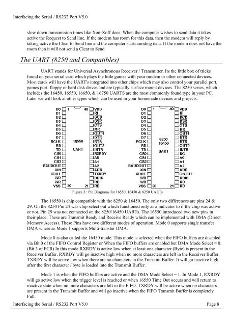
Figure 3 : Pin Diagrams for 16550, 16450 & 8250 UARTs<br />
The 16550 is chip compatible with <strong>the</strong> 8250 & 16450. The only two differences are pins 24 &<br />
29. On <strong>the</strong> 8250 Pin 24 was chip select out which functioned only as a indicator to if <strong>the</strong> chip was active<br />
or not. Pin 29 was not connected on <strong>the</strong> 8250/16450 UARTs. The 16550 introduced two new pins in<br />
<strong>the</strong>ir place. These are Transmit Ready and Receive Ready which can be implemented with DMA (Direct<br />
Memory Access). These Pins have two different modes of operation. Mode 0 supports single transfer<br />
DMA where as Mode 1 supports Multi-transfer DMA.<br />
Mode 0 is also called <strong>the</strong> 16450 mode. This mode is selected when <strong>the</strong> FIFO buffers are disabled<br />
via Bit 0 of <strong>the</strong> FIFO Control Register or When <strong>the</strong> FIFO buffers are enabled but DMA Mode Select = 0.<br />
(Bit 3 of FCR) In this mode RXRDY is active low when at least one character (Byte) is present in <strong>the</strong><br />
Receiver Buffer. RXRDY will go inactive high when no more characters are left in <strong>the</strong> Receiver Buffer.<br />
TXRDY will be active low when <strong>the</strong>re are no characters in <strong>the</strong> Transmit Buffer. It will go inactive high<br />
after <strong>the</strong> first character / byte is loaded into <strong>the</strong> Transmit Buffer.<br />
Mode 1 is when <strong>the</strong> FIFO buffers are active and <strong>the</strong> DMA Mode Select = 1. In Mode 1, RXRDY<br />
will go active low when <strong>the</strong> trigger level is reached or when 16550 Time Out occurs and will return to<br />
inactive state when no more characters are left in <strong>the</strong> FIFO. TXRDY will be active when no characters<br />
are present in <strong>the</strong> Transmit Buffer and will go inactive when <strong>the</strong> FIFO Transmit Buffer is completely<br />
Full.<br />
<strong>Interfacing</strong> <strong>the</strong> <strong>Serial</strong> / <strong>RS</strong><strong>232</strong> <strong>Port</strong> V5.0 Page 8