Interfacing the Serial/RS-232 Port
Interfacing the Serial/RS-232 Port
Interfacing the Serial/RS-232 Port

You also want an ePaper? Increase the reach of your titles
YUMPU automatically turns print PDFs into web optimized ePapers that Google loves.
<strong>Interfacing</strong> <strong>the</strong> <strong>Serial</strong> / <strong>RS</strong><strong>232</strong> <strong>Port</strong> V5.0<br />
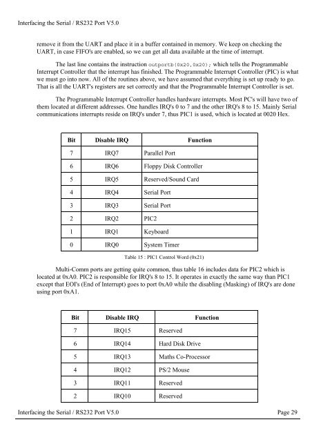
remove it from <strong>the</strong> UART and place it in a buffer contained in memory. We keep on checking <strong>the</strong><br />
UART, in case FIFO's are enabled, so we can get all data available at <strong>the</strong> time of interrupt.<br />
The last line contains <strong>the</strong> instruction outportb(0x20,0x20); which tells <strong>the</strong> Programmable<br />
Interrupt Controller that <strong>the</strong> interrupt has finished. The Programmable Interrupt Controller (PIC) is what<br />
we must go into now. All of <strong>the</strong> routines above, we have assumed that everything is set up ready to go.<br />
That is all <strong>the</strong> UART's registers are set correctly and that <strong>the</strong> Programmable Interrupt Controller is set.<br />
The Programmable Interrupt Controller handles hardware interrupts. Most PC's will have two of<br />
<strong>the</strong>m located at different addresses. One handles IRQ's 0 to 7 and <strong>the</strong> o<strong>the</strong>r IRQ's 8 to 15. Mainly <strong>Serial</strong><br />
communications interrupts reside on IRQ's under 7, thus PIC1 is used, which is located at 0020 Hex.<br />
Bit Disable IRQ Function<br />
7 IRQ7 Parallel <strong>Port</strong><br />
6 IRQ6 Floppy Disk Controller<br />
5 IRQ5 Reserved/Sound Card<br />
4 IRQ4 <strong>Serial</strong> <strong>Port</strong><br />
3 IRQ3 <strong>Serial</strong> <strong>Port</strong><br />
2 IRQ2 PIC2<br />
1 IRQ1 Keyboard<br />
0 IRQ0 System Timer<br />
Table 15 : PIC1 Control Word (0x21)<br />
Multi-Comm ports are getting quite common, thus table 16 includes data for PIC2 which is<br />
located at 0xA0. PIC2 is responsible for IRQ's 8 to 15. It operates in exactly <strong>the</strong> same way than PIC1<br />
except that EOI's (End of Interrupt) goes to port 0xA0 while <strong>the</strong> disabling (Masking) of IRQ's are done<br />
using port 0xA1.<br />
Bit Disable IRQ Function<br />
7 IRQ15 Reserved<br />
6 IRQ14 Hard Disk Drive<br />
5 IRQ13 Maths Co-Processor<br />
4 IRQ12 PS/2 Mouse<br />
3 IRQ11 Reserved<br />
2 IRQ10 Reserved<br />
<strong>Interfacing</strong> <strong>the</strong> <strong>Serial</strong> / <strong>RS</strong><strong>232</strong> <strong>Port</strong> V5.0 Page 29