Interfacing the Serial/RS-232 Port
Interfacing the Serial/RS-232 Port
Interfacing the Serial/RS-232 Port

You also want an ePaper? Increase the reach of your titles
YUMPU automatically turns print PDFs into web optimized ePapers that Google loves.
<strong>Interfacing</strong> <strong>the</strong> <strong>Serial</strong> / <strong>RS</strong><strong>232</strong> <strong>Port</strong> V5.0<br />
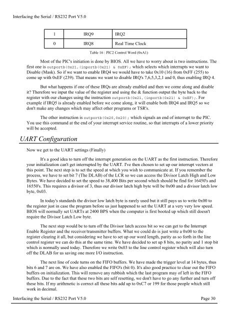
1 IRQ9 IRQ2<br />
0 IRQ8 Real Time Clock<br />
Table 16 : PIC2 Control Word (0xA1)<br />
Most of <strong>the</strong> PIC's initiation is done by BIOS. All we have to worry about is two instructions. The<br />
first one is outportb(0x21,(inportb(0x21) & 0xEF); which selects which interrupts we want to<br />
Disable (Mask). So if we want to enable IRQ4 we would have to take 0x10 (16) from 0xFF (255) to<br />
come up with 0xEF (239). That means we want to disable IRQ's 7,6,5,3,2,1 and 0, thus enabling IRQ 4.<br />
But what happens if one of <strong>the</strong>se IRQs are already enabled and <strong>the</strong>n we come along and disable<br />
it Therefore we input <strong>the</strong> value of <strong>the</strong> register and using <strong>the</strong> & function output <strong>the</strong> byte back to <strong>the</strong><br />
register with our changes using <strong>the</strong> instruction outportb(0x21,(inportb(0x21) & 0xEF);. For<br />
example if IRQ5 is already enabled before we come along, it will enable both IRQ4 and IRQ5 so we<br />
don't make any changes which may affect o<strong>the</strong>r programs or TSR's.<br />
The o<strong>the</strong>r instruction is outportb(0x20,0x20); which signals an end of interrupt to <strong>the</strong> PIC.<br />
You use this command at <strong>the</strong> end of your interrupt service routine, so that interrupts of a lower priority<br />
will be accepted.<br />
UART Configuration<br />
Now we get to <strong>the</strong> UART settings (Finally)<br />
It's a good idea to turn off <strong>the</strong> interrupt generation on <strong>the</strong> UART as <strong>the</strong> first instruction. Therefore<br />
your initialization can't get interrupted by <strong>the</strong> UART. I've <strong>the</strong>n chosen to set up our interrupt vectors at<br />
this point. The next step is to set <strong>the</strong> speed at which you wish to communicate at. If you remember <strong>the</strong><br />
process, we have to set bit 7 (The DLAB) of <strong>the</strong> LCR so we can access <strong>the</strong> Divisor Latch High and Low<br />
Bytes. We have decided to set <strong>the</strong> speed to 38,400 Bits per second which should be find for 16450's and<br />
16550's. This requires a divisor of 3, thus our divisor latch high byte will be 0x00 and a divisor latch low<br />
byte, 0x03.<br />
In today's standards <strong>the</strong> divisor low latch byte is rarely used but it still pays us to write 0x00 to<br />
<strong>the</strong> register just in case <strong>the</strong> program before us just happened to set <strong>the</strong> UART at a very very low speed.<br />
BIOS will normally set UARTs at 2400 BPS when <strong>the</strong> computer is first booted up which still doesn't<br />
require <strong>the</strong> Divisor Latch Low byte.<br />
The next step would be to turn off <strong>the</strong> Divisor latch access bit so we can get to <strong>the</strong> Interrupt<br />
Enable Register and <strong>the</strong> receiver/transmitter buffers. What we could do is just write a 0x00 to <strong>the</strong><br />
register clearing it all, but considering we have to set up our word length, parity as so forth in <strong>the</strong> line<br />
control register we can do this at <strong>the</strong> same time. We have decided to set up 8 bits, no parity and 1 stop bit<br />
which is normally used today. Therefore we write 0x03 to <strong>the</strong> line control register which will also turn<br />
off <strong>the</strong> DLAB for us saving one more I/O instruction.<br />
The next line of code turns on <strong>the</strong> FIFO buffers. We have made <strong>the</strong> trigger level at 14 bytes, thus<br />
bits 6 and 7 are on. We have also enabled <strong>the</strong> FIFO's (bit 0). It's also good practice to clear out <strong>the</strong> FIFO<br />
buffers on initialization. This will remove any rubbish which <strong>the</strong> last program may of left in <strong>the</strong> FIFO<br />
buffers. Due to <strong>the</strong> fact that <strong>the</strong>se two bits are self resetting, we don't have to go any fur<strong>the</strong>r and turn off<br />
<strong>the</strong>se bits. If my arithmetic is correct all <strong>the</strong>se bits add up to 0xC7 or 199 for those people which still<br />
work in decimal.<br />
<strong>Interfacing</strong> <strong>the</strong> <strong>Serial</strong> / <strong>RS</strong><strong>232</strong> <strong>Port</strong> V5.0 Page 30