Interfacing the Serial/RS-232 Port
Interfacing the Serial/RS-232 Port
Interfacing the Serial/RS-232 Port

Create successful ePaper yourself
Turn your PDF publications into a flip-book with our unique Google optimized e-Paper software.
<strong>Interfacing</strong> <strong>the</strong> <strong>Serial</strong> / <strong>RS</strong><strong>232</strong> <strong>Port</strong> V5.0<br />
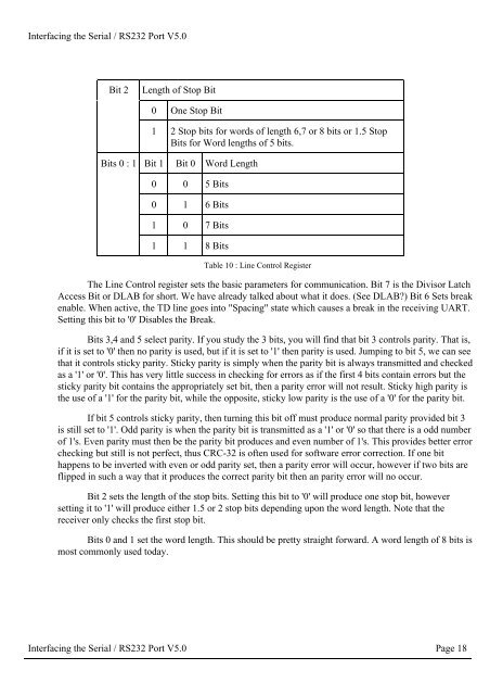
Bit 2<br />
Length of Stop Bit<br />
0 One Stop Bit<br />
1 2 Stop bits for words of length 6,7 or 8 bits or 1.5 Stop<br />
Bits for Word lengths of 5 bits.<br />
Bits 0 : 1 Bit 1 Bit 0 Word Length<br />
0 0 5 Bits<br />
0 1 6 Bits<br />
1 0 7 Bits<br />
1 1 8 Bits<br />
Table 10 : Line Control Register<br />
The Line Control register sets <strong>the</strong> basic parameters for communication. Bit 7 is <strong>the</strong> Divisor Latch<br />
Access Bit or DLAB for short. We have already talked about what it does. (See DLAB) Bit 6 Sets break<br />
enable. When active, <strong>the</strong> TD line goes into "Spacing" state which causes a break in <strong>the</strong> receiving UART.<br />
Setting this bit to '0' Disables <strong>the</strong> Break.<br />
Bits 3,4 and 5 select parity. If you study <strong>the</strong> 3 bits, you will find that bit 3 controls parity. That is,<br />
if it is set to '0' <strong>the</strong>n no parity is used, but if it is set to '1' <strong>the</strong>n parity is used. Jumping to bit 5, we can see<br />
that it controls sticky parity. Sticky parity is simply when <strong>the</strong> parity bit is always transmitted and checked<br />
as a '1' or '0'. This has very little success in checking for errors as if <strong>the</strong> first 4 bits contain errors but <strong>the</strong><br />
sticky parity bit contains <strong>the</strong> appropriately set bit, <strong>the</strong>n a parity error will not result. Sticky high parity is<br />
<strong>the</strong> use of a '1' for <strong>the</strong> parity bit, while <strong>the</strong> opposite, sticky low parity is <strong>the</strong> use of a '0' for <strong>the</strong> parity bit.<br />
If bit 5 controls sticky parity, <strong>the</strong>n turning this bit off must produce normal parity provided bit 3<br />
is still set to '1'. Odd parity is when <strong>the</strong> parity bit is transmitted as a '1' or '0' so that <strong>the</strong>re is a odd number<br />
of 1's. Even parity must <strong>the</strong>n be <strong>the</strong> parity bit produces and even number of 1's. This provides better error<br />
checking but still is not perfect, thus CRC-32 is often used for software error correction. If one bit<br />
happens to be inverted with even or odd parity set, <strong>the</strong>n a parity error will occur, however if two bits are<br />
flipped in such a way that it produces <strong>the</strong> correct parity bit <strong>the</strong>n an parity error will no occur.<br />
Bit 2 sets <strong>the</strong> length of <strong>the</strong> stop bits. Setting this bit to '0' will produce one stop bit, however<br />
setting it to '1' will produce ei<strong>the</strong>r 1.5 or 2 stop bits depending upon <strong>the</strong> word length. Note that <strong>the</strong><br />
receiver only checks <strong>the</strong> first stop bit.<br />
Bits 0 and 1 set <strong>the</strong> word length. This should be pretty straight forward. A word length of 8 bits is<br />
most commonly used today.<br />
<strong>Interfacing</strong> <strong>the</strong> <strong>Serial</strong> / <strong>RS</strong><strong>232</strong> <strong>Port</strong> V5.0 Page 18