Interfacing the Serial/RS-232 Port
Interfacing the Serial/RS-232 Port
Interfacing the Serial/RS-232 Port

You also want an ePaper? Increase the reach of your titles
YUMPU automatically turns print PDFs into web optimized ePapers that Google loves.
<strong>Interfacing</strong> <strong>the</strong> <strong>Serial</strong> / <strong>RS</strong><strong>232</strong> <strong>Port</strong> V5.0<br />
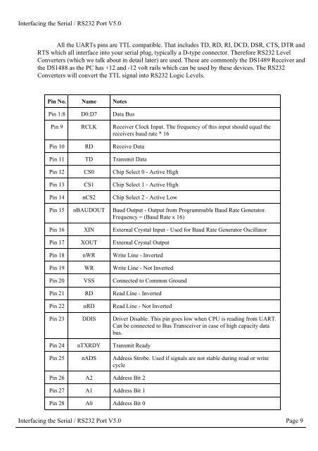
All <strong>the</strong> UARTs pins are TTL compatible. That includes TD, RD, RI, DCD, DSR, CTS, DTR and<br />
RTS which all interface into your serial plug, typically a D-type connector. Therefore <strong>RS</strong><strong>232</strong> Level<br />
Converters (which we talk about in detail later) are used. These are commonly <strong>the</strong> DS1489 Receiver and<br />
<strong>the</strong> DS1488 as <strong>the</strong> PC has +12 and -12 volt rails which can be used by <strong>the</strong>se devices. The <strong>RS</strong><strong>232</strong><br />
Converters will convert <strong>the</strong> TTL signal into <strong>RS</strong><strong>232</strong> Logic Levels.<br />
Pin No. Name Notes<br />
Pin 1:8 D0:D7 Data Bus<br />
Pin 9 RCLK Receiver Clock Input. The frequency of this input should equal <strong>the</strong><br />
receivers baud rate * 16<br />
Pin 10 RD Receive Data<br />
Pin 11 TD Transmit Data<br />
Pin 12 CS0 Chip Select 0 - Active High<br />
Pin 13 CS1 Chip Select 1 - Active High<br />
Pin 14 nCS2 Chip Select 2 - Active Low<br />
Pin 15 nBAUDOUT Baud Output - Output from Programmable Baud Rate Generator.<br />
Frequency = (Baud Rate x 16)<br />
Pin 16 XIN External Crystal Input - Used for Baud Rate Generator Oscillator<br />
Pin 17 XOUT External Crystal Output<br />
Pin 18 nWR Write Line - Inverted<br />
Pin 19 WR Write Line - Not Inverted<br />
Pin 20 VSS Connected to Common Ground<br />
Pin 21 RD Read Line - Inverted<br />
Pin 22 nRD Read Line - Not Inverted<br />
Pin 23 DDIS Driver Disable. This pin goes low when CPU is reading from UART.<br />
Can be connected to Bus Transceiver in case of high capacity data<br />
bus.<br />
Pin 24 nTXRDY Transmit Ready<br />
Pin 25 nADS Address Strobe. Used if signals are not stable during read or write<br />
cycle<br />
Pin 26 A2 Address Bit 2<br />
Pin 27 A1 Address Bit 1<br />
Pin 28 A0 Address Bit 0<br />
<strong>Interfacing</strong> <strong>the</strong> <strong>Serial</strong> / <strong>RS</strong><strong>232</strong> <strong>Port</strong> V5.0 Page 9